EP3773111B1 - Verfahren und vorrichtung zur durchführung von reinigungsarbeiten - Google Patents
Verfahren und vorrichtung zur durchführung von reinigungsarbeiten Download PDFInfo
- Publication number
- EP3773111B1 EP3773111B1 EP19799537.6A EP19799537A EP3773111B1 EP 3773111 B1 EP3773111 B1 EP 3773111B1 EP 19799537 A EP19799537 A EP 19799537A EP 3773111 B1 EP3773111 B1 EP 3773111B1
- Authority
- EP
- European Patent Office
- Prior art keywords
- cleaning
- data
- contamination
- cleaning apparatus
- robotic
- Prior art date
- Legal status (The legal status is an assumption and is not a legal conclusion. Google has not performed a legal analysis and makes no representation as to the accuracy of the status listed.)
- Active
Links
Images


Classifications
-
- A—HUMAN NECESSITIES
- A47—FURNITURE; DOMESTIC ARTICLES OR APPLIANCES; COFFEE MILLS; SPICE MILLS; SUCTION CLEANERS IN GENERAL
- A47L—DOMESTIC WASHING OR CLEANING; SUCTION CLEANERS IN GENERAL
- A47L9/00—Details or accessories of suction cleaners, e.g. mechanical means for controlling the suction or for effecting pulsating action; Storing devices specially adapted to suction cleaners or parts thereof; Carrying-vehicles specially adapted for suction cleaners
- A47L9/28—Installation of the electric equipment, e.g. adaptation or attachment to the suction cleaner; Controlling suction cleaners by electric means
- A47L9/2805—Parameters or conditions being sensed
- A47L9/2826—Parameters or conditions being sensed the condition of the floor
-
- A—HUMAN NECESSITIES
- A47—FURNITURE; DOMESTIC ARTICLES OR APPLIANCES; COFFEE MILLS; SPICE MILLS; SUCTION CLEANERS IN GENERAL
- A47L—DOMESTIC WASHING OR CLEANING; SUCTION CLEANERS IN GENERAL
- A47L9/00—Details or accessories of suction cleaners, e.g. mechanical means for controlling the suction or for effecting pulsating action; Storing devices specially adapted to suction cleaners or parts thereof; Carrying-vehicles specially adapted for suction cleaners
- A47L9/28—Installation of the electric equipment, e.g. adaptation or attachment to the suction cleaner; Controlling suction cleaners by electric means
- A47L9/2805—Parameters or conditions being sensed
- A47L9/281—Parameters or conditions being sensed the amount or condition of incoming dirt or dust
- A47L9/2815—Parameters or conditions being sensed the amount or condition of incoming dirt or dust using optical detectors
-
- A—HUMAN NECESSITIES
- A47—FURNITURE; DOMESTIC ARTICLES OR APPLIANCES; COFFEE MILLS; SPICE MILLS; SUCTION CLEANERS IN GENERAL
- A47L—DOMESTIC WASHING OR CLEANING; SUCTION CLEANERS IN GENERAL
- A47L9/00—Details or accessories of suction cleaners, e.g. mechanical means for controlling the suction or for effecting pulsating action; Storing devices specially adapted to suction cleaners or parts thereof; Carrying-vehicles specially adapted for suction cleaners
- A47L9/28—Installation of the electric equipment, e.g. adaptation or attachment to the suction cleaner; Controlling suction cleaners by electric means
- A47L9/2836—Installation of the electric equipment, e.g. adaptation or attachment to the suction cleaner; Controlling suction cleaners by electric means characterised by the parts which are controlled
- A47L9/2842—Suction motors or blowers
-
- A—HUMAN NECESSITIES
- A47—FURNITURE; DOMESTIC ARTICLES OR APPLIANCES; COFFEE MILLS; SPICE MILLS; SUCTION CLEANERS IN GENERAL
- A47L—DOMESTIC WASHING OR CLEANING; SUCTION CLEANERS IN GENERAL
- A47L9/00—Details or accessories of suction cleaners, e.g. mechanical means for controlling the suction or for effecting pulsating action; Storing devices specially adapted to suction cleaners or parts thereof; Carrying-vehicles specially adapted for suction cleaners
- A47L9/28—Installation of the electric equipment, e.g. adaptation or attachment to the suction cleaner; Controlling suction cleaners by electric means
- A47L9/2836—Installation of the electric equipment, e.g. adaptation or attachment to the suction cleaner; Controlling suction cleaners by electric means characterised by the parts which are controlled
- A47L9/2847—Surface treating elements
-
- A—HUMAN NECESSITIES
- A47—FURNITURE; DOMESTIC ARTICLES OR APPLIANCES; COFFEE MILLS; SPICE MILLS; SUCTION CLEANERS IN GENERAL
- A47L—DOMESTIC WASHING OR CLEANING; SUCTION CLEANERS IN GENERAL
- A47L9/00—Details or accessories of suction cleaners, e.g. mechanical means for controlling the suction or for effecting pulsating action; Storing devices specially adapted to suction cleaners or parts thereof; Carrying-vehicles specially adapted for suction cleaners
- A47L9/28—Installation of the electric equipment, e.g. adaptation or attachment to the suction cleaner; Controlling suction cleaners by electric means
- A47L9/2836—Installation of the electric equipment, e.g. adaptation or attachment to the suction cleaner; Controlling suction cleaners by electric means characterised by the parts which are controlled
- A47L9/2852—Elements for displacement of the vacuum cleaner or the accessories therefor, e.g. wheels, casters or nozzles
-
- A—HUMAN NECESSITIES
- A47—FURNITURE; DOMESTIC ARTICLES OR APPLIANCES; COFFEE MILLS; SPICE MILLS; SUCTION CLEANERS IN GENERAL
- A47L—DOMESTIC WASHING OR CLEANING; SUCTION CLEANERS IN GENERAL
- A47L9/00—Details or accessories of suction cleaners, e.g. mechanical means for controlling the suction or for effecting pulsating action; Storing devices specially adapted to suction cleaners or parts thereof; Carrying-vehicles specially adapted for suction cleaners
- A47L9/28—Installation of the electric equipment, e.g. adaptation or attachment to the suction cleaner; Controlling suction cleaners by electric means
- A47L9/2857—User input or output elements for control, e.g. buttons, switches or displays
-
- A—HUMAN NECESSITIES
- A47—FURNITURE; DOMESTIC ARTICLES OR APPLIANCES; COFFEE MILLS; SPICE MILLS; SUCTION CLEANERS IN GENERAL
- A47L—DOMESTIC WASHING OR CLEANING; SUCTION CLEANERS IN GENERAL
- A47L9/00—Details or accessories of suction cleaners, e.g. mechanical means for controlling the suction or for effecting pulsating action; Storing devices specially adapted to suction cleaners or parts thereof; Carrying-vehicles specially adapted for suction cleaners
- A47L9/28—Installation of the electric equipment, e.g. adaptation or attachment to the suction cleaner; Controlling suction cleaners by electric means
- A47L9/2894—Details related to signal transmission in suction cleaners
-
- B—PERFORMING OPERATIONS; TRANSPORTING
- B25—HAND TOOLS; PORTABLE POWER-DRIVEN TOOLS; MANIPULATORS
- B25J—MANIPULATORS; CHAMBERS PROVIDED WITH MANIPULATION DEVICES
- B25J11/00—Manipulators not otherwise provided for
- B25J11/008—Manipulators for service tasks
- B25J11/0085—Cleaning
-
- B—PERFORMING OPERATIONS; TRANSPORTING
- B25—HAND TOOLS; PORTABLE POWER-DRIVEN TOOLS; MANIPULATORS
- B25J—MANIPULATORS; CHAMBERS PROVIDED WITH MANIPULATION DEVICES
- B25J9/00—Program-controlled manipulators
- B25J9/16—Program controls
- B25J9/1656—Program controls characterised by programming, planning systems for manipulators
- B25J9/1664—Program controls characterised by programming, planning systems for manipulators characterised by motion, path, trajectory planning
-
- G—PHYSICS
- G05—CONTROLLING; REGULATING
- G05D—SYSTEMS FOR CONTROLLING OR REGULATING NON-ELECTRIC VARIABLES
- G05D1/00—Control of position, course, altitude or attitude of land, water, air or space vehicles, e.g. using automatic pilots
- G05D1/0011—Control of position, course, altitude or attitude of land, water, air or space vehicles, e.g. using automatic pilots associated with a remote control arrangement
- G05D1/0044—Control of position, course, altitude or attitude of land, water, air or space vehicles, e.g. using automatic pilots associated with a remote control arrangement by providing the operator with a computer generated representation of the environment of the vehicle, e.g. virtual reality, maps
-
- G—PHYSICS
- G05—CONTROLLING; REGULATING
- G05D—SYSTEMS FOR CONTROLLING OR REGULATING NON-ELECTRIC VARIABLES
- G05D1/00—Control of position, course, altitude or attitude of land, water, air or space vehicles, e.g. using automatic pilots
- G05D1/20—Control system inputs
- G05D1/24—Arrangements for determining position or orientation
- G05D1/247—Arrangements for determining position or orientation using signals provided by artificial sources external to the vehicle, e.g. navigation beacons
- G05D1/249—Arrangements for determining position or orientation using signals provided by artificial sources external to the vehicle, e.g. navigation beacons from positioning sensors located off-board the vehicle, e.g. from cameras
-
- G—PHYSICS
- G05—CONTROLLING; REGULATING
- G05D—SYSTEMS FOR CONTROLLING OR REGULATING NON-ELECTRIC VARIABLES
- G05D1/00—Control of position, course, altitude or attitude of land, water, air or space vehicles, e.g. using automatic pilots
- G05D1/60—Intended control result
- G05D1/648—Performing a task within a working area or space, e.g. cleaning
-
- G—PHYSICS
- G06—COMPUTING OR CALCULATING; COUNTING
- G06N—COMPUTING ARRANGEMENTS BASED ON SPECIFIC COMPUTATIONAL MODELS
- G06N3/00—Computing arrangements based on biological models
- G06N3/02—Neural networks
- G06N3/08—Learning methods
-
- A—HUMAN NECESSITIES
- A47—FURNITURE; DOMESTIC ARTICLES OR APPLIANCES; COFFEE MILLS; SPICE MILLS; SUCTION CLEANERS IN GENERAL
- A47L—DOMESTIC WASHING OR CLEANING; SUCTION CLEANERS IN GENERAL
- A47L2201/00—Robotic cleaning machines, i.e. with automatic control of the travelling movement or the cleaning operation
- A47L2201/04—Automatic control of the travelling movement; Automatic obstacle detection
-
- A—HUMAN NECESSITIES
- A47—FURNITURE; DOMESTIC ARTICLES OR APPLIANCES; COFFEE MILLS; SPICE MILLS; SUCTION CLEANERS IN GENERAL
- A47L—DOMESTIC WASHING OR CLEANING; SUCTION CLEANERS IN GENERAL
- A47L2201/00—Robotic cleaning machines, i.e. with automatic control of the travelling movement or the cleaning operation
- A47L2201/06—Control of the cleaning action for autonomous devices; Automatic detection of the surface condition before, during or after cleaning
-
- G—PHYSICS
- G05—CONTROLLING; REGULATING
- G05D—SYSTEMS FOR CONTROLLING OR REGULATING NON-ELECTRIC VARIABLES
- G05D2101/00—Details of software or hardware architectures used for the control of position
- G05D2101/10—Details of software or hardware architectures used for the control of position using artificial intelligence [AI] techniques
- G05D2101/15—Details of software or hardware architectures used for the control of position using artificial intelligence [AI] techniques using machine learning, e.g. neural networks
-
- G—PHYSICS
- G05—CONTROLLING; REGULATING
- G05D—SYSTEMS FOR CONTROLLING OR REGULATING NON-ELECTRIC VARIABLES
- G05D2105/00—Specific applications of the controlled vehicles
- G05D2105/10—Specific applications of the controlled vehicles for cleaning, vacuuming or polishing
Definitions
- the invention relates to a method and apparatus for executing a cleaning operation, based on a contamination level of a cleaning space.
- AI systems are computer systems for implementing human-level intelligence. Unlike general rule-based smart systems, the AI systems autonomously learn and make decisions, and get smarter. The more the AI systems are used, the more recognition rates of the AI systems increase and the more accurately the AI systems understand user preferences. As such, the general rule-based smart systems are increasingly replaced by deep-learning-based AI systems.
- AI technology includes machine learning (or deep learning) and element technologies using machine learning.
- Machine learning is an algorithm technology for autonomously classifying and learning features of input data
- element technologies are technologies for mimicking functions of human brains, e.g., cognition and decision, by using a machine learning algorithm such as deep learning, and include technological fields such as linguistic understanding, visual understanding, inference/prediction, knowledge expression, and operation control.
- Linguistic understanding is a technology for recognizing and applying/processing verbal or written languages of people, and includes natural language processing, machine translation, dialogue systems, questions and answers, speech recognition/synthesis, etc.
- Visual understanding is a technology for recognizing and processing objects as in human views, and includes object recognition, object tracking, image search, human recognition, scene understanding, space understanding, image enhancement, etc.
- Inference/ prediction is a technology for determining and logically inferring and predicting information, and includes knowledge/probability-based inference, optimized prediction, preference-based planning, recommendation, etc.
- Knowledge expression is a technology for automating human experience information into knowledge data, and includes knowledge construction (e.g., data generation/classification), knowledge management (e.g., data utilization), etc.
- Operation control is a technology for controlling autonomous driving of vehicles and motion of robots, and includes motion control (e.g., steering, collision, or driving control), manipulation control (e.g., behavior control), etc.
- Robotic cleaning apparatuses need to efficiently clean a cleaning space in various operation modes and environments, and thus a technology for appropriately determining a cleaning target area under various conditions is required.
- EP2508957A2 discloses a robot cleaner, and remote controlling system and method of the robot cleaner.
- a cleaning map may be created by searching for a region to be cleaned, and a contaminant degree map may be created by detecting a contamination material and a contaminant degree according to each position within the cleaning region.
- the cleaning map and the contaminant degree map with respect to the cleaning region may be received at a remote place through the terminal device. This may allow a user to easily check information on a cleaning state, a contamination state, etc. of the cleaning region, and to control the robot cleaner based on the checked information.
- KR20100109289A discloses a robot cleaner with a real-time sensing function and a control method thereof to efficiently perform cleaning by calculating an optimum cleaning route.
- a robot cleaner with a real-time sensing function comprises sensors and a robot body.
- the sensors are installed on inner walls and a ceiling and sense the state of inside.
- Each sensor comprises a photographing unit, a wireless communication unit, and a controller.
- the photographing unit photographs the bottom of inside.
- the wireless communication unit wirelessly transmits the photographed image to the robot body.
- the controller controls the photographing unit and the wireless communication unit.
- the robot body calculates an optimum cleaning route and performs cleaning.
- KR101459245B discloses a method for controlling a robotic cleaner using the cooperative game theory.
- the method for controlling a robotic cleaner according to an embodiment of the present invention includes the steps of: receiving utility functions, which are determined based on cleaning environment data, from another robotic cleaner; determining an effective utility set based on the received utility functions; determining a negotiation solution related with a cleaning method based on conditions previously set in the effective utility set; and transferring a control data determined based on the negotiation solution to another robotic cleaner.
- Another aspect of the invention is to provide a robotic cleaning system and method capable of determining a cleaning target area and a priority of the cleaning target area by using a learning model.
- Another aspect of the invention is to provide a robotic cleaning system and method capable of efficiently controlling a robotic cleaning apparatus in a plurality of operation modes and environments by using contamination map data per a time period.
- a robotic cleaning apparatus for cleaning a cleaning space.
- the robotic cleaning apparatus includes a communication interface, a memory storing one or more instructions, and at least one processor configured to execute the one or more instructions to control the robotic cleaning apparatus, execute the one or more instructions to acquire contamination data indicating a contamination level of the cleaning space, transmit map data of the cleaning space and the contamination data to a server, receive, from the server, contamination map data generated based on the contamination data and the map data, wherein the contamination map data is generated by the server based on another map data and another contamination map data received from another robotic cleaning apparatus, the contamination data, the map data, and wherein a similarity of the other map data and the map data is greater than a threshold value, determine at least one cleaning target area in the cleaning space, based on a current time and the contamination map data, determine a priority and a cleaning strength for the at least one cleaning target area and clean the determined at least one cleaning target area according to the determined priority and cleaning strength, wherein the contamination map data comprises: information indicating
- a method, performed by a robotic cleaning apparatus, of cleaning a cleaning space includes acquiring contamination data indicating a contamination level of the cleaning space, transmitting map data of the cleaning space and the contamination data to a server, receiving, from the server, contamination map data generated based on the contamination data and the map data, wherein the contamination map data is generated by the server based on another map data and another contamination map data provided from another robotic cleaning apparatus, the contamination data, the map data, and wherein a similarity of the other map data and the map data is greater than a threshold value; determining at least one cleaning target area in the cleaning space, based on a current time and the contamination map data; determining a priority and a cleaning strength for the at least one cleaning target area; and cleaning the determined at least one cleaning target area according to the determined priority and cleaning strength, wherein the contamination map data comprises information indicating locations of contaminated areas in the cleaning space, contamination levels of the contaminated areas, and locations of objects in the cleaning space, and wherein the contamination map
- a non-transitory computer program product includes a computer-readable recording medium having recorded thereon a plurality of instructions that instruct at least one processor to perform the method above.
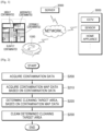
- FIG. 1 is a schematic diagram of a cleaning system according to an embodiment of the invention.
- the cleaning system may include a robotic cleaning apparatus 1000, a server 2000, and at least one external device 3000.
- the robotic cleaning apparatus 1000 may clean a cleaning space while moving in the cleaning space.
- the cleaning space may be a space to be cleaned, e.g., a home or an office.
- the robotic cleaning apparatus 1000 is a robotic apparatus capable of autonomously moving by using wheels or the like, and may perform a cleaning function while moving in the cleaning space.
- the robotic cleaning apparatus 1000 may collect contamination data about contamination in the cleaning space, generate contamination map data and determine a cleaning target area, based on the generated contamination map data.
- the robotic cleaning apparatus 1000 may predict contaminated regions in the cleaning space by using the contamination map data and determine a priority of and a cleaning strength for the cleaning target area considering the predicted contaminated regions.
- the contamination map data may include map information of the cleaning space and information indicating contaminated areas, and the robotic cleaning apparatus 1000 may generate the contamination map data per a certain time period (e.g., a predetermined time period).
- the robotic cleaning apparatus 1000 may use at least one learning model to generate the contamination map data and determine the cleaning target area.
- the learning model may be operated by at least one of the robotic cleaning apparatus 1000 or the server 2000.
- the server 2000 may generate the contamination map data and determine the cleaning target area in association with the robotic cleaning apparatus 1000.
- the server 2000 may comprehensively manage a plurality of robotic cleaning apparatuses and a plurality of external devices 3000.
- the server 2000 may use information collected from another robotic cleaning apparatus (not shown), contamination map data of another cleaning space, etc. to determine the contamination map data and the cleaning target area of the robotic cleaning apparatus 1000.
- the external device 3000 may generate contamination data about contamination in the cleaning space and data required to determine a status of the cleaning space and provide the generated data to the robotic cleaning apparatus 1000 or the server 2000.
- the external device 3000 may be installed in the cleaning space.
- the external device 3000 may include, for example, a closed-circuit television (CCTV), a sensor, or a home appliance, but is not limited thereto.
- CCTV closed-circuit television
- a network is a comprehensive data communication network capable of enabling appropriate communication between network entities illustrated in FIG. 1 , e.g., a local area network (LAN), a wide area network (WAN), a value added network (VAN), a mobile radio communication network, a satellite communication network, or a combination thereof, and may include the wired Internet, the wireless Internet, and a mobile communication network.
- Wireless communication may include, for example, wireless local area network (WLAN) (or Wi-Fi) communication, Bluetooth communication, Bluetooth low energy (BLE) communication, Zigbee communication, Wi-Fi direct (WFD) communication, ultra-wideband (UWB) communication, Infrared Data Association (IrDA) communication, and near field communication (NFC), but is not limited thereto.
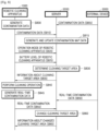
- FIG. 2 is a flowchart of a method, performed by the robotic cleaning apparatus 1000, of determining a cleaning target area, based on contamination data, according to an embodiment of the invention.
- the robotic cleaning apparatus 1000 may acquire contamination data.
- the robotic cleaning apparatus 1000 may generate contamination data of a cleaning space by using a camera and a sensor of the robotic cleaning apparatus 1000.
- the robotic cleaning apparatus 1000 may generate image data indicating a contamination level of the cleaning space, by photographing the cleaning space with the camera while cleaning the cleaning space.
- the robotic cleaning apparatus 1000 may generate sensing data indicating a dust quantity in the cleaning space, by sensing the cleaning space through a dust sensor while cleaning the cleaning space.
- the robotic cleaning apparatus 1000 may receive contamination data from the external device 3000.
- a CCTV installed in the cleaning space may photograph the cleaning space and, when a motion of contaminating the cleaning space is detected, the CCTV may provide image data including the detected motion, to the robotic cleaning apparatus 1000.
- a dust sensor installed in the cleaning space may provide sensing data about a dust quantity of the cleaning space to the robotic cleaning apparatus 1000.
- the external device 3000 may provide the contamination data generated by the external device 3000, to the server 2000, and the robotic cleaning apparatus 1000 may receive the contamination data generated by the external device 3000, from the server 2000.
- the contamination data may be used to determine a contaminated location and a contamination level of the cleaning space.
- the contamination data includes information about a location where and a time when the contamination data is generated.
- the robotic cleaning apparatus 1000 may acquire contamination map data based on the contamination data.
- the robotic cleaning apparatus 1000 may generate and update the contamination map data by using the acquired contamination data.
- the contamination map data may include a map of the cleaning space and information indicating locations and contamination levels of contaminated areas in the cleaning space.
- the contamination map data may be generated per a time period and indicate the locations and the contamination levels of the contaminated areas in the cleaning space, in each time period.
- the robotic cleaning apparatus 1000 may generate map data of the cleaning space by recognizing a location of the robotic cleaning apparatus 1000 while moving.
- the robotic cleaning apparatus 1000 may generate the contamination map data indicating the contaminated areas in the cleaning space, by using the contamination data and the map data.
- the map data of the cleaning space may include, for example, data about at least one of a navigation map used to move while cleaning, a simultaneous localization and mapping (SLAM) map used for location recognition, or an obstacle recognition map including information about recognized obstacles.
- SLAM simultaneous localization and mapping
- the contamination map data may indicate, for example, locations of rooms and furniture in the cleaning space, and include information about the locations and the contamination levels of the contaminated areas in the cleaning space.
- the robotic cleaning apparatus 1000 may generate the contamination map data by, for example, applying the map data and the contamination data of the cleaning space to a learning model for generating the contamination map data.
- the robotic cleaning apparatus 1000 may request the contamination map data from the server 2000.
- the robotic cleaning apparatus 1000 may provide the map data and the contamination data of the cleaning space to the server 2000, and the server 2000 may generate the contamination map data by applying the map data and the contamination data of the cleaning space to the learning model for generating the contamination map data.
- the robotic cleaning apparatus 1000 may determine a cleaning target area, based on the contamination map data.
- the robotic cleaning apparatus 1000 may predict the locations and the contamination levels of the contaminated areas in the cleaning space, based on the contamination map data and determine at least one cleaning target area, based on an operation mode and an apparatus state of the robotic cleaning apparatus 1000.
- the robotic cleaning apparatus 1000 may determine a priority of and a cleaning strength for the cleaning target area in the cleaning space considering the operation mode and the apparatus state of the robotic cleaning apparatus 1000.
- the robotic cleaning apparatus 1000 may determine the cleaning strength of the robotic cleaning apparatus 1000 by, for example, determining a speed and suction power of the robotic cleaning apparatus 1000. For example, at a high cleaning strength, the robotic cleaning apparatus 1000 may strongly suck up dust while moving slowly. For example, at a low cleaning strength, the robotic cleaning apparatus 1000 may weakly suck up dust while moving fast. For example, the robotic cleaning apparatus 1000 may strongly suck up dust while moving fast, or weakly suck up dust while moving slowly.
- the operation mode of the robotic cleaning apparatus 1000 may include, for example, a normal mode, a quick mode, a power-saving mode, and a low-noise mode, but is not limited thereto.
- the robotic cleaning apparatus 1000 may determine the cleaning target area and the priority of the cleaning target area considering an operating time of the robotic cleaning apparatus 1000 to preferentially clean a seriously contaminated area within the operating time.
- the robotic cleaning apparatus 1000 may determine the cleaning target area and the cleaning strength to clean a seriously contaminated area with low noise.
- the robotic cleaning apparatus 1000 may determine the cleaning target area and the priority of the cleaning target area considering a battery level of the robotic cleaning apparatus 1000.
- the robotic cleaning apparatus 1000 determines the cleaning target area by applying information about the robotic cleaning apparatus 1000 and the cleaning space to a learning model for determining the cleaning target area. For example, the robotic cleaning apparatus 1000 determines the cleaning target area, the priority of and the cleaning strength for the cleaning target area, etc. by inputting information about the operation mode of the robotic cleaning apparatus 1000, the apparatus state of the robotic cleaning apparatus 1000, and a motion of a user in the cleaning space, to the learning model for determining the cleaning target area.
- the robotic cleaning apparatus 1000 cleans the determined cleaning target area.
- the robotic cleaning apparatus 1000 cleans the cleaning space according to the priority of and the cleaning strength for the cleaning target area.
- the robotic cleaning apparatus 1000 collects contamination data about contamination of the cleaning space in real time while cleaning, and change the cleaning target area by reflecting the contamination data collected in real time.
- FIG. 3 is a flowchart of a method, performed by the robotic cleaning apparatus 1000, of acquiring contamination data, according to an embodiment of the invention.
- the robotic cleaning apparatus 1000 may detect contamination by using a sensor of the robotic cleaning apparatus 1000.
- the robotic cleaning apparatus 1000 may include, for example, an infrared sensor, an ultrasonic sensor, a radio frequency (RF) sensor, a geomagnetic sensor, a position sensitive device (PSD) sensor, and a dust sensor.
- the robotic cleaning apparatus 1000 may detect a location and motion of the robotic cleaning apparatus 1000 and determine locations and contamination levels of contaminated areas by using the sensors of the robotic cleaning apparatus 1000 while cleaning.
- the robotic cleaning apparatus 1000 may generate contamination data including information about the contamination levels measured in the contaminated areas and the locations of the contaminated areas.
- the robotic cleaning apparatus 1000 may include, in the contamination data, information about a time when the contamination data is generated.
- the robotic cleaning apparatus 1000 may photograph the contaminated areas by using a camera of the robotic cleaning apparatus 1000.
- the robotic cleaning apparatus 1000 may generate image data of contaminants by photographing the contaminated areas determined as having the contaminants, while cleaning.
- the robotic cleaning apparatus 1000 may include, in the contamination data, information about a time when the contamination data is generated.
- the robotic cleaning apparatus 1000 may receive contamination data from the external device 3000.
- At least one external device 3000 may be installed in a cleaning space to generate the contamination data.
- the robotic cleaning apparatus 1000 may determine the location of the external device 3000 in the cleaning space by communicating with the external device 3000.
- the robotic cleaning apparatus 1000 may determine the location of the external device 3000 in the cleaning space by determining the location of the robotic cleaning apparatus 1000 in the cleaning space and a relative location between the robotic cleaning apparatus 1000 and the external device 3000.
- the external device 3000 may determine the location thereof in the cleaning space and provide information indicating the location of the external device 3000, to the robotic cleaning apparatus 1000.
- the external device 3000 may include, for example, a CCTV, an Internet protocol (IP) camera, an ultrasonic sensor, an infrared sensor, and a dust sensor.
- the CCTV may continuously photograph the cleaning space and, when a motion of contaminating the cleaning space is detected, the CCTV may provide video data or captured image data including the detected motion, to the robotic cleaning apparatus 1000.
- the dust sensor may provide sensing data about a dust quantity of the cleaning space to the robotic cleaning apparatus 1000 in real time or periodically.
- the external device 3000 is a home appliance
- the home appliance may provide information about an operating state thereof to the robotic cleaning apparatus 1000 in real time or periodically.
- the external device 3000 may include, in the contamination data, information about a time when the contamination data is generated.
- the robotic cleaning apparatus 1000 may acquire contamination map data.
- the robotic cleaning apparatus 1000 may generate the contamination map data by analyzing the contamination data generated by the robotic cleaning apparatus 1000 and the contamination data generated by the external device 3000.
- the contamination data may include information about the locations and the contamination levels of the contaminated areas in the cleaning space.
- the robotic cleaning apparatus 1000 may generate the contamination map data indicating a contaminated location and a contamination level in the cleaning space, by using map data of the cleaning space and the contamination data acquired in operations S300 to S320.
- the robotic cleaning apparatus 1000 may generate the contamination map data per a time period.
- the robotic cleaning apparatus 1000 may generate the contamination map data by data about motion of the robotic cleaning apparatus 1000 and the contamination data to a learning model for generating the contamination map data.
- the learning model for generating the contamination map data may be previously learned by the robotic cleaning apparatus 1000 or the server 2000.
- the robotic cleaning apparatus 1000 may provide the data about motion of the robotic cleaning apparatus 1000 and the contamination data to the server 2000, and the server 2000 may apply the data about motion of the robotic cleaning apparatus 1000 and the contamination data to the learning model for generating the contamination map data.
- FIG. 4 is a flowchart of a method, performed by the robotic cleaning apparatus 1000, of determining a priority of and a cleaning strength for a cleaning target area considering an operation mode of the robotic cleaning apparatus 1000, according to an embodiment of the invention.
- the robotic cleaning apparatus 1000 may determine an operation mode of the robotic cleaning apparatus 1000.
- the robotic cleaning apparatus 1000 may determine the operation mode of the robotic cleaning apparatus 1000 considering an environment of a cleaning space, a current time, and an apparatus state of the robotic cleaning apparatus 1000.
- the robotic cleaning apparatus 1000 may determine the operation mode of the robotic cleaning apparatus 1000 considering information about whether a user is present in the cleaning space, information about a motion of the user, a current time, a battery level of the robotic cleaning apparatus 1000, etc.
- the robotic cleaning apparatus 1000 may determine the operation mode of the robotic cleaning apparatus 1000 by collecting the information about whether a user is present in the cleaning space, the information about a motion of the user, the current time, and the battery level of the robotic cleaning apparatus 1000 and analyzing the collected information.
- the operation mode of the robotic cleaning apparatus 1000 may include, for example, a normal mode, a quick mode, a power-saving mode, and a low-noise mode, but is not limited thereto.
- the operation mode of the robotic cleaning apparatus 1000 will be described in detail below.
- the robotic cleaning apparatus 1000 may determine the operation mode of the robotic cleaning apparatus 1000, based on a user input.
- the robotic cleaning apparatus 1000 may determine a priority of and a cleaning strength for a cleaning target area, based on contamination map data and the operation mode. For example, when the operation mode is the quick mode, the robotic cleaning apparatus 1000 may determine the cleaning target area, and the priority of and the cleaning strength for the cleaning target area to clean only a cleaning target area having a contamination level equal to or greater than a certain value. For example, when the operation mode is the low-noise mode, the robotic cleaning apparatus 1000 may determine the cleaning target area, and the priority of and the cleaning strength for the cleaning target area to slowly clean a cleaning target area having a contamination level equal to or greater than a certain value, at a low cleaning strength.
- the robotic cleaning apparatus 1000 determines the cleaning target area, the priority of the cleaning target area, and the cleaning strength for the cleaning target area according to the operation mode in the above description, the invention is not limited thereto.
- the robotic cleaning apparatus 1000 may not determine the operation mode of the robotic cleaning apparatus 1000 and, in this case, the robotic cleaning apparatus 1000 may determine the cleaning target area, and the priority of and the cleaning strength for the cleaning target area considering the environment of the cleaning space, the current time, and the apparatus state of the robotic cleaning apparatus 1000.
- the cleaning strength may be differently set per a cleaning target area.
- the robotic cleaning apparatus 1000 may determine the cleaning target area and the priority of and the cleaning strength for the cleaning target area by inputting information about the environment of the cleaning space, the current time, and the apparatus state of the robotic cleaning apparatus 1000 to a learning model for determining the cleaning target area.
- the learning model for determining the cleaning target area may be previously learned by the robotic cleaning apparatus 1000 or the server 2000.
- the robotic cleaning apparatus 1000 may provide the information about the environment of the cleaning space, the current time, and the apparatus state of the robotic cleaning apparatus 1000 to the server 2000, and the server 2000 may input the information about the environment of the cleaning space, the current time, and the apparatus state of the robotic cleaning apparatus 1000 to the learning model for determining the cleaning target area.
- the robotic cleaning apparatus 1000 may perform cleaning according to the determined priority and cleaning strength.
- the robotic cleaning apparatus 1000 may clean the cleaning target area according to the priority of the cleaning target area at a different cleaning strength per a cleaning target area.
- the robotic cleaning apparatus 1000 may update the contamination map data.
- the robotic cleaning apparatus 1000 may update the contamination map data by reflecting the real-time contamination data acquired in operation S430. In this case, the robotic cleaning apparatus 1000 may reflect a time when the real-time contamination data is generated, to update the contamination map data.
- the robotic cleaning apparatus 1000 may change the cleaning target area, and the priority of and the cleaning strength for the cleaning target area.
- the robotic cleaning apparatus 1000 may change the cleaning target area, and the priority of and the cleaning strength for the cleaning target area, which are determined in operation S410, considering the real-time contamination data acquired in operation S430.
- the robotic cleaning apparatus 1000 uses the learning model for generating the contamination map data and the learning model for determining the cleaning target area in FIGS. 3 and 4 , respectively, the invention is not limited thereto.
- the robotic cleaning apparatus 1000 may acquire data about the contamination map data and the cleaning target area by using a learning model for generating the contamination map data and determining the cleaning target area.
- FIG. 5 is a flowchart of a method, performed by the robotic cleaning apparatus 1000, of determining an operation mode of the robotic cleaning apparatus 1000, according to an embodiment of the invention.
- the robotic cleaning apparatus 1000 may check a current time. In operation S510, the robotic cleaning apparatus 1000 may check a battery level of the robotic cleaning apparatus 1000.
- the robotic cleaning apparatus 1000 may receive real-time data from a CCTV in a cleaning space.
- the CCTV may provide image data obtained by photographing the motion of the user, to the robotic cleaning apparatus 1000.
- the CCTV may provide information indicating that the motion of the user is detected, to the robotic cleaning apparatus 1000.
- the robotic cleaning apparatus 1000 may determine and change an operation mode of the robotic cleaning apparatus 1000.
- the robotic cleaning apparatus 1000 may determine and change the operation mode of the robotic cleaning apparatus 1000 considering the current time, the battery level, and the real-time CCTV data.
- the robotic cleaning apparatus 1000 may determine and change the operation mode considering the current time in such a manner that the robotic cleaning apparatus 1000 operates in a low-noise mode at night. For example, the robotic cleaning apparatus 1000 may determine and change the operation mode considering the battery level in such a manner that the robotic cleaning apparatus 1000 operates in a power-saving mode when the battery level is equal to or less than a certain value. For example, when the user is present in the cleaning space, the robotic cleaning apparatus 1000 may determine and change the operation mode in such a manner that the robotic cleaning apparatus 1000 operates in a quick mode. For example, when the user is not present in the cleaning space, the robotic cleaning apparatus 1000 may determine and change the operation mode in such a manner that the robotic cleaning apparatus 1000 operates in a normal mode.
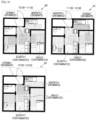
- FIG. 6 is a schematic diagram showing contamination map data according to an embodiment of the invention.
- the contamination map data may include information about a plan view of a cleaning space.
- the cleaning space may be divided into a plurality of rooms, and the contamination map data may include information about locations of the rooms in the cleaning space, information about locations of furniture, information about locations of contaminated areas, and information about contamination levels of the contaminated areas.
- the contamination map data may be differently generated per a time period.
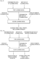
- FIGS. 7 and 8 are flowcharts of methods, performed by the robotic cleaning apparatus 1000, of determining and changing a cleaning target area in association with the server 2000, according to various embodiments of the invention.
- the server 2000 may determine and change a cleaning target area by acquiring contamination data from the robotic cleaning apparatus 1000.
- the robotic cleaning apparatus 1000 may generate contamination data.
- the robotic cleaning apparatus 1000 may receive contamination data from the external device 3000.
- the robotic cleaning apparatus 1000 may provide the generated contamination data and the received contamination data to the server 2000.
- the robotic cleaning apparatus 1000 may provide the generated contamination data and the received contamination data to the server 2000 in real time or periodically.
- the server 2000 may generate and update contamination map data.
- the server 2000 may receive map data generated by the robotic cleaning apparatus 1000, from the robotic cleaning apparatus 1000.
- the server 2000 may generate the contamination map data by analyzing the received map data and contamination data.
- the server 2000 may generate the contamination map data by applying the map data and the contamination data to a learning model for generating the contamination map data, but is not limited thereto.
- the server 2000 may generate the contamination map data by using other map data and other contamination map data of another cleaning space, which are received from another robotic cleaning apparatus (not shown).
- the other map data of the other cleaning space which is used by the server 2000, may be similar to the map data of the cleaning space of the robotic cleaning apparatus 1000 by a certain value or more.
- the contamination map data of the other cleaning space may be used by the server 2000.
- the server 2000 may determine whether users in the other cleaning space are similar to users in the cleaning space of the robotic cleaning apparatus 1000. In this case, information such as occupations, ages, and genders of the users may be used to determine similarity between the users.
- the robotic cleaning apparatus 1000 may provide information about an operation mode of the robotic cleaning apparatus 1000 to the server 2000.
- the robotic cleaning apparatus 1000 may determine the operation mode, based on a user input. Alternatively, the robotic cleaning apparatus 1000 may determine the operation mode considering an environment of the cleaning space and a state of the robotic cleaning apparatus 1000.
- the robotic cleaning apparatus 1000 may provide information about an apparatus state of the robotic cleaning apparatus 1000 to the server 2000.
- the robotic cleaning apparatus 1000 may periodically transmit the information about the apparatus state of the robotic cleaning apparatus 1000 to the server 2000, but is not limited thereto.
- the server 2000 may determine a cleaning target area.
- the server 2000 may determine a location of the cleaning target area, a priority of the cleaning target area, and a cleaning strength for the cleaning target area.
- the server 2000 may determine the location of the cleaning target area, the priority of the cleaning target area, and the cleaning strength for the cleaning target area considering the contamination map data, the operation mode of the robotic cleaning apparatus 1000, and the apparatus state of the robotic cleaning apparatus 1000.
- the cleaning strength may be determined by, for example, a speed and suction power of the robotic cleaning apparatus 1000.
- the server 2000 may determine the location of the cleaning target area, the priority of the cleaning target area, and the cleaning strength for the cleaning target area by applying the contamination map data and information about the operation mode of the robotic cleaning apparatus 1000 and the apparatus state of the robotic cleaning apparatus 1000 to a learning model for determining the cleaning target area.
- the server 2000 may provide information about the cleaning target area to the robotic cleaning apparatus 1000.
- the robotic cleaning apparatus 1000 may perform a cleaning operation.
- the robotic cleaning apparatus 1000 may perform cleaning, based on information about the location of the cleaning target area, the priority of the cleaning target area, and the cleaning strength for the cleaning target area, which is provided from the server 2000.
- the robotic cleaning apparatus 1000 may generate real-time contamination data.
- the robotic cleaning apparatus 1000 may receive real-time contamination data from the external device 3000.
- the robotic cleaning apparatus 1000 may provide the generated real-time contamination data and the received real-time contamination data to the server 2000.
- the server 2000 may change the cleaning target area, based on the real-time contamination data.
- the server 2000 may change the cleaning target area by applying the real-time contamination data to the learning model for determining the cleaning target area.
- the server 2000 may provide information about the changed cleaning target area to the robotic cleaning apparatus 1000.
- contamination data generated by the external device 3000 may be provided from the external device 3000 to the server 2000 (at operation S800).
- the external device 3000 may provide contamination data generated by the external device 3000, to the server 2000.
- the external device 3000 may provide real-time contamination data generated by the external device 3000, to the server 2000.
- the server 2000 may manage the robotic cleaning apparatus 1000 and the external device 3000 together by using an integrated ID of a user.
- Operations S815 to S845 and S855 to S865 are akin to corresponding operations S715 to S745 and S755 to S765 shown in FIG. 7 , and a detailed description thereof will be omitted.
- the robotic cleaning apparatus 1000 may provide contamination data to the server 2000, in operation S815, the server 2000 may generated and update the contamination data, in operation S820, the robotic cleaning apparatus 1000 may provide an operation mode of the robotic cleaning apparatus to the server 2000, in operation S825, the robotic cleaning apparatus 1000 may provide information related to the battery level of the robotic cleaning apparatus to the server 2000, in operation S830, the server may determine the cleaning target area based on the received information, in operation S835, the server 2000 may provide information about the cleaning target area to the robotic cleaning apparatus, in operation S840, the robotic cleaning apparatus 1000 may perform the cleaning operation of the cleaning target area, in operation S845, the robotic cleaning apparatus may generate real-time contamination data., in operation S855, the robotic cleaning apparatus 1000 provides real-time contamination data to the server 2000, in operation S860, based on the received real-time data, the server 2000 may change the cleaning target area, and in operation S865, the server 2000 may provide information about the changed cleaning target area to the robotic cleaning apparatus.
- FIGS. 9, 10 , 11, and 12 are schematic diagrams showing examples in which a cleaning target area is determined using learning models, according to various embodiments of the invention.
- contamination map data of the cleaning space may be determined.
- the first learning model may be a learning model for generating the contamination map data of the cleaning space.
- the contamination map data of the cleaning space, data about a status of the cleaning space, and data about an apparatus state of the robotic cleaning apparatus 1000 are applied to a second learning model, a cleaning target area, and a priority of and a cleaning strength for the cleaning target area may be determined.
- the second learning model may be a learning model for determining the cleaning target area.
- contamination map data of the cleaning space may be determined.
- the third learning model may be a learning model for generating the contamination map data of the cleaning space.
- the contamination map data of the cleaning space, data about a status of the cleaning space, and data about an apparatus state of the robotic cleaning apparatus 1000 are applied to a fourth learning model, an operation mode of the robotic cleaning apparatus 1000, a cleaning target area, and a priority of and a cleaning strength for the cleaning target area may be determined.
- the fourth learning model may be a learning model for determining the operation mode of the robotic cleaning apparatus 1000 and the cleaning target area.
- the fifth learning model may be a learning model for determining the contamination map data of the cleaning space, the operation mode of the robotic cleaning apparatus 1000, and the cleaning target area.
- the sixth learning model may be a learning model for determining the cleaning target area.
- the contamination map data of the cleaning space, the operation mode of the robotic cleaning apparatus 1000, and the cleaning target area are determined using various types of learning models in FIGS. 9 to 12 , the invention is not limited thereto. Learning models different in types and numbers from those illustrated in FIGS. 9 to 12 may be used to determine the contamination map data of the cleaning space, the operation mode of the robotic cleaning apparatus 1000, and the cleaning target area. Different and various types of information may be input to the learning models.
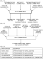
- FIG. 13 is a table for describing operation modes of the robotic cleaning apparatus 1000, according to an embodiment of the invention.
- the operation modes of the robotic cleaning apparatus 1000 may include, for example, a normal mode, a quick mode, a low-noise mode, and a power-saving mode.
- the normal mode may be an operation mode for normal cleaning.
- the quick mode may be an operation mode for quick cleaning.
- the robotic cleaning apparatus 1000 may clean only a contaminated area having a contamination level equal to or greater than a certain value, with high suction power while moving at a high speed.
- the robotic cleaning apparatus 1000 may determine a cleaning target area to quickly complete cleaning within the set operating time.
- the low-noise mode may be an operation mode for minimizing noise.
- the robotic cleaning apparatus 1000 may perform cleaning in the low-noise mode.
- the robotic cleaning apparatus 1000 may perform cleaning with low suction power while moving at a low speed.
- the power-saving mode may be an operation mode for reducing battery consumption.
- the robotic cleaning apparatus 1000 may operate with a low power consumption and determine a cleaning target area considering the battery level.
- the above-described operation modes of the robotic cleaning apparatus 1000 are merely examples, and the operation modes of the robotic cleaning apparatus 1000 are not limited thereto.
- the robotic cleaning apparatus 1000 may operate in operation modes different from the above-described operation modes and perform cleaning by using a combination of two or more operation modes.
- the operation mode of the robotic cleaning apparatus 1000 may not be set in a simple manner.
- the robotic cleaning apparatus 1000 may operate by continuously setting and changing weights for quick cleaning, low-noise cleaning, and save cleaning.
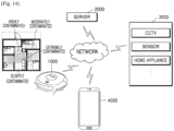
- FIG. 14 is a schematic diagram of a cleaning system according to another embodiment of the invention.
- the cleaning system may include the robotic cleaning apparatus 1000, the server 2000, at least one external device 3000, and a mobile device 4000.
- the mobile device 4000 may communicate with the robotic cleaning apparatus 1000, the server 2000, and the at least one external device 3000 through a network.
- the mobile device 4000 may perform some of the functions of the robotic cleaning apparatus 1000, which are described above in relation to FIGS. 1 to 13 .
- the mobile device 4000 may display a graphical user interface (GUI) for controlling the robotic cleaning apparatus 1000, and a map showing a contamination level of a cleaning space, on a screen of the mobile device 4000.
- GUI graphical user interface
- the mobile device 4000 may receive information about a state of the robotic cleaning apparatus 1000 and a status of the cleaning space from the robotic cleaning apparatus 1000, and use a learning model to determine how to clean the cleaning space.
- the mobile device 4000 may use at least one learning model to generate contamination map data and determine a cleaning target area. In this case, the mobile device 4000 may perform operations of the robotic cleaning apparatus 1000, as described below with reference to FIGS. 20 to 23 .
- the mobile device 4000 may include, for example, a display (not shown), a communication interface (not shown) used to communicate with an external device, a memory (not shown) storing one or more instructions, at least one sensor (not shown), and a processor (not shown) executing the instructions stored in the memory.
- the processor of the mobile device 4000 may control operations of the other elements of the mobile device 4000 by executing the instructions stored in the memory.
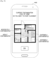
- FIGS. 15 to 17 are schematic diagrams showing an example in which the mobile device 4000 controls the robotic cleaning apparatus 1000 to operate in a certain operation mode, according to an embodiment of the invention.
- the mobile device 4000 may receive contamination map data from the robotic cleaning apparatus 1000 and display the received contamination map data on a screen of the mobile device 4000.
- the mobile device 4000 may display the contamination map data indicating a current contamination level of a home, and a GUI for determining whether to start cleaning by using the robotic cleaning apparatus 1000, on the screen.
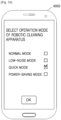
- the mobile device 4000 may display a GUI for selecting an operation mode of the robotic cleaning apparatus 1000, on the screen.
- the mobile device 4000 may display a list of operation modes of the robotic cleaning apparatus 1000.
- the mobile device 4000 may display an operation mode list including a normal mode, a low-noise mode, a quick mode, and a power-saving mode, and receive a user input for selecting the quick mode.
- the mobile device 4000 may request the robotic cleaning apparatus 1000 to perform cleaning in the quick mode.
- the mobile device 4000 may display a GUI showing a result of cleaning performed using the robotic cleaning apparatus 1000.
- the robotic cleaning apparatus 1000 may clean a cleaning space in the quick mode according to the request of the mobile device 4000.
- the robotic cleaning apparatus 1000 may clean an extremely contaminated area and a highly contaminated area of the cleaning space in the quick mode and provide contamination map data indicating a result of cleaning, to the mobile device 4000.
- the mobile device 4000 may display the contamination map data indicating the result of cleaning.
- the mobile device 4000 may display a GUI for determining whether to schedule a cleaning using the robotic cleaning apparatus 1000.
- FIG. 18 is a block diagram of the robotic cleaning apparatus 1000 according to an embodiment of the invention. .
- the robotic cleaning apparatus 1000 may include a user inputter 1100, a communication unit 1200, a memory 1400, a camera 1500, a mover 1600, an outputter 1700, a sensor unit 1800, and a processor 1300, and the outputter 1700 may include a speaker 1710 and a display 1720.
- the user inputter 1100 may receive user inputs for controlling operations of the robotic cleaning apparatus 1000.
- the user inputter 1100 may include, for example, a key pad, a dome switch, a touchpad (e.g., a capacitive overlay, resistive overlay, infrared beam, surface acoustic wave, integral strain gauge, or piezoelectric touchpad), a jog wheel, and a jog switch, but is not limited thereto.
- the communication unit 1200 may include one or more communication modules for communicating with the server 2000 and the external device 3000.
- the communication unit 1200 may include a short-range wireless communication unit and a mobile communication unit.
- the short-range wireless communication unit may include, for example, a Bluetooth communication unit, a BLE communication unit, an NFC unit, a WLAN (or Wi-Fi) communication unit, a Zigbee communication unit, an IrDA communication unit, a WFD communication unit, a UWB communication unit, or an Ant+ communication unit, but is not limited thereto.
- the mobile communication unit transmits and receives radio signals to and from at least one of a base station, an external terminal, or a server in a mobile communication network.
- the radio signals may include voice call signals, video call signals, or various types of data due to transception of text/multimedia messages.
- the memory 1400 may store programs for controlling operations of the robotic cleaning apparatus 1000.
- the memory 1400 may include at least one instruction for controlling operations of the robotic cleaning apparatus 1000.
- the memory 1400 may store, for example, map data, contamination data, contamination map data, and data about a cleaning target area.
- the memory 1400 may store, for example, a learning model for generating the contamination map data, and a learning model for determining the cleaning target area.
- the programs stored in the memory 1400 may be classified into a plurality of modules according to functions thereof.
- the memory 1400 may include at least one type of storage medium among flash memory, a hard disk, a multimedia card micro, card-type memory (e.g., secure digital (SD) or extreme digital (XD) memory), random access memory (RAM), static random access memory (SRAM), read-only memory (ROM), electrically erasable programmable ROM (EEPROM), programmable ROM (PROM), magnetic memory, a magnetic disc, and an optical disc.
- card-type memory e.g., secure digital (SD) or extreme digital (XD) memory
- RAM random access memory
- SRAM static random access memory
- ROM read-only memory
- EEPROM electrically erasable programmable ROM
- PROM programmable ROM
- the camera 1500 may photograph an ambient environment of the robotic cleaning apparatus 1000.
- the camera 1500 may photograph the ambient environment of the robotic cleaning apparatus 1000 or a floor while the robotic cleaning apparatus 1000 is performing cleaning.
- the display 1720 displays information processed by the robotic cleaning apparatus 1000.
- the display 1720 may display a user interface for controlling the robotic cleaning apparatus 1000 or a user interface indicating a state of the robotic cleaning apparatus 1000.
- the display 1720 may be used not only as an output device but also as an input device.
- the sensor unit 1800 may include at least one sensor for sensing data about an operation and a state of the robotic cleaning apparatus 1000, and data about contamination of a cleaning space.
- the sensor unit 1800 may include, for example, at least one of an infrared sensor, an ultrasonic sensor, an RF sensor, a geomagnetic sensor, or a PSD sensor.
- the sensor unit 1800 may detect a contaminated area near the robotic cleaning apparatus 1000 and detect a contamination level.
- the sensor unit 1800 may detect an obstacle near the robotic cleaning apparatus 1000, or detect whether a cliff is present near the robotic cleaning apparatus 1000.
- the sensor unit 1800 may further include an operation detection sensor for detecting operations of the robotic cleaning apparatus 1000.
- the sensor unit 1800 may include a gyro sensor, a wheel sensor, and an acceleration sensor.
- the gyro sensor may detect a rotation direction and a rotation angle when the robotic cleaning apparatus 1000 moves.
- the wheel sensor may be connected to the left and right wheels to detect the number of revolutions of each wheel.
- the wheel sensor may be a rotary encoder but is not limited thereto.
- the processor 1300 may generally control overall operations of the robotic cleaning apparatus 1000.
- the processor 1300 may control the user inputter 1100, the communication unit 1200, the memory 1400, the camera 1500, the mover 1600, the outputter 1700, and the sensor unit 1800 by executing the programs stored in the memory 1400.
- the processor 1300 may control the operations of the robotic cleaning apparatus 1000, which are described above in relation to FIGS. 1 to 13 , by controlling the user inputter 1100, the communication unit 1200, the memory 1400, the camera 1500, the mover 1600, the outputter 1700, and the sensor unit 1800.
- the processor 1300 may acquire contamination data.
- the processor 1300 may generate contamination data of the cleaning space by using a camera and a sensor of the robotic cleaning apparatus 1000.
- the processor 1300 may generate image data indicating a contamination level of the cleaning space, by photographing the cleaning space with the camera while cleaning the cleaning space.
- the processor 1300 may generate sensing data indicating a dust quantity in the cleaning space, by sensing the cleaning space through a dust sensor while cleaning the cleaning space.
- the processor 1300 may receive contamination data from the external device 3000.
- the external device 3000 may provide the contamination data generated by the external device 3000, to the server 2000, and the processor 1300 may receive the contamination data generated by the external device 3000, from the server 2000.
- the processor 1300 may acquire contamination map data based on the contamination data.
- the processor 1300 may generate and update the contamination map data by using the acquired contamination data.
- the contamination map data may include a map of the cleaning space and information indicating locations and contamination levels of contaminated areas in the cleaning space.
- the contamination map data may be generated per a time period and indicate the locations and the contamination levels of the contaminated areas in the cleaning space, in each time period.
- the processor 1300 may generate map data of the cleaning space by recognizing a location of the robotic cleaning apparatus 1000 while moving.
- the processor 1300 may generate the contamination map data indicating the contaminated areas in the cleaning space, by using the contamination data and the map data.
- the processor 1300 may generate the contamination map data by, for example, applying the map data and the contamination data of the cleaning space to the learning model for generating the contamination map data.
- the processor 1300 may request the contamination map data from the server 2000.
- the processor 1300 may provide the map data and the contamination data of the cleaning space to the server 2000, and the server 2000 may generate the contamination map data by applying the map data and the contamination data of the cleaning space to the learning model for generating the contamination map data.
- the processor 1300 may determine a cleaning target area, based on the contamination map data.
- the processor 1300 may predict the locations and the contamination levels of the contaminated areas in the cleaning space, based on the contamination map data, and determine at least one cleaning target area, based on an operation mode and an apparatus state of the robotic cleaning apparatus 1000.
- the processor 1300 may determine a priority of and a cleaning strength for the cleaning target area in the cleaning space considering the operation mode and the apparatus state of the robotic cleaning apparatus 1000.
- the processor 1300 may determine the cleaning strength of the robotic cleaning apparatus 1000 by, for example, determining a speed and suction power of the robotic cleaning apparatus 1000.
- the processor 1300 may determine the cleaning target area by applying information about the robotic cleaning apparatus 1000 and the cleaning space to the learning model for determining the cleaning target area. For example, the processor 1300 may determine the cleaning target area, and the priority of and the cleaning strength for the cleaning target area by inputting information about the operation mode of the robotic cleaning apparatus 1000, the apparatus state of the robotic cleaning apparatus 1000, and a motion of a user in the cleaning space, to the learning model for determining the cleaning target area.
- the processor 1300 may clean the determined cleaning target area.
- the processor 1300 may clean the cleaning space according to the priority of and the cleaning strength for the cleaning target area.
- the processor 1300 may collect contamination data about contamination of the cleaning space in real time while cleaning, and change the cleaning target area by reflecting the contamination data collected in real time.
- FIG. 19 is a block diagram of the server 2000 according to an embodiment of the invention.
- the server 2000 may include a communication unit 2100, a storage 2200, and a processor 2300.
- the communication unit 2100 may include one or more communication modules for communicating with the robotic cleaning apparatus 1000 and the external device 3000.
- the communication unit 2100 may include a short-range wireless communication unit and a mobile communication unit.
- the short-range wireless communication unit may include, for example, a Bluetooth communication unit, a BLE communication unit, an NFC unit, a WLAN (or Wi-Fi) communication unit, a Zigbee communication unit, an IrDA communication unit, a WFD communication unit, a UWB communication unit, or an Ant+ communication unit, but is not limited thereto.
- the mobile communication unit transmits and receives radio signals to and from at least one of a base station, an external terminal, or a server in a mobile communication network.
- the radio signals may include voice call signals, video call signals, or various types of data due to transception of text/multimedia messages.
- the storage 2200 may store programs for controlling operations of the server 2000.
- the storage 2200 may include at least one instruction for controlling operations of the server 2000.
- the storage 2200 may store, for example, map data, contamination data, contamination map data, and data about a cleaning target area.
- the storage 2200 may store, for example, a learning model for generating the contamination map data, and a learning model for determining the cleaning target area.
- the programs stored in the storage 2200 may be classified into a plurality of modules according to functions thereof.
- the storage 2200 may include a plurality of databases (DBs) to comprehensively manage, for example, user identifiers (IDs) of a plurality of users, contamination map data of a plurality of robotic cleaning apparatuses, and sensing data of a plurality of external devices.
- DBs databases
- the processor 2300 may generally control overall operations of the server 2000.
- the processor 2300 may control the communication unit 2100 and the storage 2200 by executing the programs stored in the storage 2200.
- the processor 2300 may control the operations of the server 2000, which are described above in relation to FIGS. 1 to 13 , by controlling the communication unit 2100 and the storage 2200.
- the processor 2300 may receive contamination data from at least one of the robotic cleaning apparatus 1000 or the external device 3000.
- the processor 2300 may receive the contamination data from at least one of the robotic cleaning apparatus 1000 or the external device 3000 in real time or periodically.
- the processor 2300 may generate and update contamination map data.
- the processor 2300 may receive map data generated by the robotic cleaning apparatus 1000, from the robotic cleaning apparatus 1000.
- the processor 2300 may generate the contamination map data by analyzing the received map data and contamination data.
- the processor 2300 may generate the contamination map data by applying the map data and the contamination data to the learning model for generating the contamination map data, but is not limited thereto.
- the processor 2300 may generate the contamination map data by using other map data and other contamination map data of another cleaning space, which are received from another robotic cleaning apparatus (not shown).
- the other map data of the other cleaning space which is used by the processor 2300, may be similar to the map data of the cleaning space of the robotic cleaning apparatus 1000 by a certain value or more.
- the contamination map data of the other cleaning space may be used by the processor 2300.
- the processor 2300 may determine whether users in the other cleaning space are similar to users in the cleaning space of the robotic cleaning apparatus 1000. In this case, information such as occupations, ages, and genders of the users may be used to determine similarity between the users.
- the processor 2300 may receive information about an operation mode of the robotic cleaning apparatus 1000 from the robotic cleaning apparatus 1000.
- the processor 2300 may receive information about an apparatus state of the robotic cleaning apparatus 1000 from the robotic cleaning apparatus 1000.
- the processor 2300 may determine a cleaning target area.
- the processor 2300 may determine a location of the cleaning target area, a priority of the cleaning target area, and a cleaning strength for the cleaning target area.
- the processor 2300 may determine the location of the cleaning target area, the priority of the cleaning target area, and the cleaning strength for the cleaning target area considering the contamination map data, the operation mode of the robotic cleaning apparatus 1000, and the apparatus state of the robotic cleaning apparatus 1000.
- the cleaning strength may be determined by, for example, a speed and suction power of the robotic cleaning apparatus 1000.
- the processor 2300 may determine the location of the cleaning target area, the priority of the cleaning target area, and the cleaning strength for the cleaning target area by applying the contamination map data and information about the operation mode of the robotic cleaning apparatus 1000 and the apparatus state of the robotic cleaning apparatus 1000 to the learning model for determining the cleaning target area.
- the processor 2300 may receive real-time contamination data from at least one of the robotic cleaning apparatus 1000 or the external device 3000.
- the processor 2300 may change the cleaning target area, based on the real-time contamination data.
- the processor 2300 may change the cleaning target area by applying the real-time contamination data to the learning model for determining the cleaning target area.
- the processor 2300 may provide information about the changed cleaning target area to the robotic cleaning apparatus 1000.
- the processor 2300 may manage the robotic cleaning apparatus 1000 and the external device 3000 together by using an integrated ID of a user.
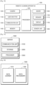
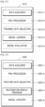
- FIG. 20 is a block diagram of the processor 1300 according to an embodiment of the invention.
- the processor 1300 may include a data learner 1310 and a data recognizer 1320.
- the data learner 1310 may learn criteria for at least one of generation of contamination map data, determination of a cleaning target area, or determination of an operation mode of the robotic cleaning apparatus 1000.
- the data learner 1310 may learn which data is used for decision of at least one of the generation of the contamination map data, the determination of the cleaning target area, or the determination of the operation mode of the robotic cleaning apparatus 1000, and learn criteria about how to decide at least one of the generation of the contamination map data, the determination of the cleaning target area, or the determination of the operation mode of the robotic cleaning apparatus 1000 by using the data.
- the data learner 1310 may learn the criteria for at least one of the generation of the contamination map data, the determination of the cleaning target area, or the determination of the operation mode of the robotic cleaning apparatus 1000 by acquiring data to be used for learning and applying the acquired data to a data recognition model to be described below.
- the data recognizer 1320 may decide at least one of the generation of the contamination map data, the determination of the cleaning target area, or the determination of the operation mode of the robotic cleaning apparatus 1000, based on data.
- the data recognizer 1320 may perform at least one of the generation of the contamination map data, the determination of the cleaning target area, or the determination of the operation mode of the robotic cleaning apparatus 1000 by using certain data and a learned data recognition model.
- the data recognizer 1320 may perform at least one of the generation of the contamination map data, the determination of the cleaning target area, or the determination of the operation mode of the robotic cleaning apparatus 1000 by acquiring the certain data according to the learned preset criteria and using the acquired data as an input value of the data recognition model.
- a resultant value output from the data recognition model by using the acquired data as an input value may be used to update the data recognition model.
- At least one of the data learner 1310 or the data recognizer 1320 may be produced in the form of at least one hardware chip and be mounted in an electronic apparatus.
- at least one of the data learner 1310 or the data recognizer 1320 may be produced in the form of an exclusive hardware chip for artificial intelligence (AI), or as a part of a general-use processor (e.g., a central processing unit (CPU) or an application processor) or a dedicated graphics processor (e.g., a graphics processing unit (GPU)), and be mounted in various electronic apparatuses.
- a general-use processor e.g., a central processing unit (CPU) or an application processor
- a dedicated graphics processor e.g., a graphics processing unit (GPU)
- the data learner 1310 and the data recognizer 1320 may be mounted together in one electronic apparatus or mounted separately in different electronic apparatuses.
- one of the data learner 1310 and the data recognizer 1320 may be included in an electronic apparatus, and the other may be included in a server.
- model information constructed by the data learner 1310 may be provided to the data recognizer 1320 and data input to the data recognizer 1320 may be provided to the data learner 1310 as additional training data.
- At least one of the data learner 1310 or the data recognizer 1320 may be implemented as a software module.
- the software module may be stored in a non-transitory computer-readable recording medium.
- one or more software modules may be provided by an operating system (OS) or a certain application.
- OS operating system
- some of the one or more software modules may be provided by the OS and the others may be provided by the certain application.
- FIG. 21 is a block diagram of the data learner 1310 according to an embodiment of the invention.
- the data learner 1310 may include a data acquirer 1310-1, a pre-processor 1310-2, a training data selector 1310-3, a model learner 1310-4, and a model evaluator 1310-5.
- the data acquirer 1310-1 may acquire data required for at least one of generation of contamination map data, determination of a cleaning target area, or determination of an operation mode of the robotic cleaning apparatus 1000.
- the data acquirer 1310-1 may acquire data required for learning for at least one of the generation of the contamination map data, the determination of the cleaning target area, or the determination of the operation mode of the robotic cleaning apparatus 1000.
- At least one of an image captured by the robotic cleaning apparatus 1000, sensing data sensed by the robotic cleaning apparatus 1000, an image captured by the external device 3000, sensing data sensed by the external device 3000, map data of a cleaning space, contamination map data of another cleaning space, information about a status of the cleaning space, or information about a state of the robotic cleaning apparatus 1000 may be acquired for the learning.
- the data acquired for the learning is not limited thereto and, for example, data inputable to the learning models of FIGS. 9 to 12 may be acquired for the learning.
- the training data selector 1310-3 may select data required for the learning, from the pre-processed data.
- the selected data may be provided to the model learner 1310-4.
- the training data selector 1310-3 may select the data required for the learning, from the pre-processed data according to preset criteria for at least one of the generation of the contamination map data, the determination of the cleaning target area, or the determination of the operation mode of the robotic cleaning apparatus 1000.
- the training data selector 1310-3 may select the data according to preset criteria learned by the model learner 1310-4 to be described below.
- the model learner 1310-4 may learn criteria for at least one of the generation of the contamination map data, the determination of the cleaning target area, or the determination of the operation mode of the robotic cleaning apparatus 1000, based on training data.
- the model learner 1310-4 may learn criteria about which training data needs to be used for at least one of the generation of the contamination map data, the determination of the cleaning target area, or the determination of the operation mode of the robotic cleaning apparatus 1000.
- the model learner 1310-4 may learn a data recognition model used for at least one of the generation of the contamination map data, the determination of the cleaning target area, or the determination of the operation mode of the robotic cleaning apparatus 1000 by using training data.
- the data recognition model may be a previously constructed model.
- the data recognition model may be a model previously constructed by receiving basic training data.
- the data recognition model may be constructed considering an applicable field of the recognition model, the purpose of learning, or the computer performance of an apparatus, or the like.
- the data recognition model may be, for example, a model based on a neural network.
- a model based on a deep neural network (DNN), a recurrent neural network (RNN), or a bidirectional recurrent deep neural network (BRDNN) may be used as the data recognition model.
- DNN deep neural network
- RNN recurrent neural network
- BBDNN bidirectional recurrent deep neural network
- the data recognition model is not limited thereto.
- the model learner 1310-4 may determine a data recognition model highly relevant to the input training data and the basic training data, as a data recognition model to be learned.
- the basic training data may be previously classified according to data types, and the data recognition models may be previously constructed according to data types.
- the basic training data may be previously classified according to various criteria, e.g., regions where the training data is generated, times when the training data is generated, sizes of the training data, genres of the training data, creators of the training data, and types of objects in the training data.
- the model learner 1310-4 may learn the data recognition model by, for example, using a learning algorithm including error back-propagation or gradient descent.
- the model learner 1310-4 may learn the data recognition model through, for example, supervised learning using training data as an input value.
- the model learner 1310-4 may learn the data recognition model through, for example, unsupervised learning for finding criteria for determining a situation, by autonomously learning types of data required to determine the situation without any supervision.
- the model learner 1310-4 may learn the data recognition model through, for example, reinforcement learning using feedback on whether a result of determining the situation through learning is correct.
- the model learner 1310-4 may store the learned data recognition model.
- the model learner 1310-4 may store the learned data recognition model in memory of an electronic apparatus including the data recognizer 1320.
- the model learner 1310-4 may store the learned data recognition model in memory of an electronic apparatus including the data recognizer 1320 to be described below.
- the model learner 1310-4 may store the learned data recognition model in memory of a server connected to an electronic apparatus in a wired or wireless network.
- the memory storing the learned data recognition model may also store, for example, commands or data related to at least one other element of the electronic apparatus.
- the memory may also store software and/or programs.
- the programs may include, for example, a kernel, middleware, application programming interfaces (APIs), and/or application programs (or "applications").
- the model evaluator 1310-5 may input evaluation data to the data recognition model and, when recognition results output using the evaluation data do not satisfy a certain criterion, the model evaluator 1310-5 may request the model learner 1310-4 to learn again.
- the evaluation data may be preset data for evaluating the data recognition model.
- the model evaluator 1310-5 may evaluate that the certain criterion is not satisfied. For example, assuming that the certain criterion is defined a ratio of 2%, when the learned data recognition model outputs wrong recognition results for more than 20 pieces of evaluation data out of a total of 1,000 pieces of evaluation data, the model evaluator 1310-5 may evaluate that the learned data recognition model is not appropriate.
- the model evaluator 1310-5 may evaluate whether each of the learned data recognition models satisfies the certain criterion and determine a model satisfying the certain criterion, as a final data recognition model. In this case, when a plurality of models satisfy the certain criterion, the model evaluator 1310-5 may determine a preset model or a certain number of models selected in the order of evaluation scores, as a final data recognition model(s).
- At least one of the data acquirer 1310-1, the pre-processor 1310-2, the training data selector 1310-3, the model learner 1310-4, or the model evaluator 1310-5 in the data learner 1310 may be produced in the form of at least one hardware chip and be mounted in an electronic apparatus.
- at least one of the data acquirer 1310-1, the pre-processor 1310-2, the training data selector 1310-3, the model learner 1310-4, or the model evaluator 1310-5 may be produced in the form of an exclusive hardware chip for AI, or as a part of a general-use processor (e.g., a CPU or an application processor) or a dedicated graphics processor (e.g., a GPU), and be mounted in various electronic apparatuses.
- a general-use processor e.g., a CPU or an application processor
- a dedicated graphics processor e.g., a GPU
- the data acquirer 1310-1, the pre-processor 1310-2, the training data selector 1310-3, the model learner 1310-4, and the model evaluator 1310-5 may be mounted together in one electronic apparatus or mounted separately in different electronic apparatuses.
- some of the data acquirer 1310-1, the pre-processor 1310-2, the training data selector 1310-3, the model learner 1310-4, and the model evaluator 1310-5 may be included in an electronic apparatus, and the others may be included in a server.
- At least one of the data acquirer 1310-1, the pre-processor 1310-2, the training data selector 1310-3, the model learner 1310-4, or the model evaluator 1310-5 may be implemented as a software module.
- the software module may be stored in a non-transitory computer-readable recording medium.
- one or more software modules may be provided by an OS or a certain application.
- some of the one or more software modules may be provided by the OS and the others may be provided by the certain application.
- FIG. 22 is a block diagram of the data recognizer 1320 according to an embodiment of the invention.
- the data recognizer 1320 may include a data acquirer 1320-1, a pre-processor 1320-2, a feature data selector 1320-3, a recognition result provider 1320-4, and a model updater 1320-5.
- the data acquirer 1320-1 may acquire data required for at least one of generation of contamination map data, determination of a cleaning target area, or determination of an operation mode of the robotic cleaning apparatus 1000, and the pre-processor 1320-2 may pre-process the acquired data to be usable for at least one of the generation of the contamination map data, the determination of the cleaning target area, or the determination of the operation mode of the robotic cleaning apparatus 1000.
- the pre-processor 1320-2 may process the acquired data to a preset format in such a manner that the recognition result provider 1320-4 to be described below may use the acquired data for at least one of the generation of the contamination map data, the determination of the cleaning target area, or the determination of the operation mode of the robotic cleaning apparatus 1000.
- the feature data selector 1320-3 may select data required for at least one of the generation of the contamination map data, the determination of the cleaning target area, or the determination of the operation mode of the robotic cleaning apparatus 1000, from the pre-processed data.
- the selected data may be provided to the recognition result provider 1320-4.
- the feature data selector 1320-3 may select a part of or the whole pre-processed data according to preset criteria for at least one of the generation of the contamination map data, the determination of the cleaning target area, or the determination of the operation mode of the robotic cleaning apparatus 1000.
- the feature data selector 1320-3 may select the data according to preset criteria learned by the model learner 1310-4 described above in relation to FIG. 21 .
- the recognition result provider 1320-4 may perform at least one of the generation of the contamination map data, the determination of the cleaning target area, or the determination of the operation mode of the robotic cleaning apparatus 1000 by applying the selected data to a data recognition model.
- the recognition result provider 1320-4 may provide a recognition result according to a purpose of data recognition.
- the recognition result provider 1320-4 may apply the selected data to the data recognition model by using the data selected by the feature data selector 1320-3, as an input value.
- the recognition result may be determined by the data recognition model.
- At least one of an image captured by the robotic cleaning apparatus 1000, sensing data sensed by the robotic cleaning apparatus 1000, an image captured by the external device 3000, sensing data sensed by the external device 3000, map data of a cleaning space, contamination map data of another cleaning space, information about a status of the cleaning space, or information about a state of the robotic cleaning apparatus 1000 may be acquired for the recognition.
- the data acquired for the recognition is not limited thereto and, for example, data inputable to the learning models of FIGS. 9 to 12 may be acquired for the recognition.
- the model updater 1320-5 may request updating of the data recognition model, based on evaluation of the recognition result provided from the recognition result provider 1320-4. For example, the model updater 1320-5 may request the model learner 1310-4 to update the data recognition model, by providing the recognition result provided from the recognition result provider 1320-4, to the model learner 1310-4.
- At least one of the data acquirer 1320-1, the pre-processor 1320-2, the feature data selector 1320-3, the recognition result provider 1320-4, or the model updater 1320-5 in the data recognizer 1320 may be produced in the form of at least one hardware chip and be mounted in an electronic apparatus.
- at least one of the data acquirer 1320-1, the pre-processor 1320-2, the feature data selector 1320-3, the recognition result provider 1320-4, or the model updater 1320-5 may be produced in the form of an exclusive hardware chip for AI, or as a part of a general-use processor (e.g., a CPU or an application processor) or a dedicated graphics processor (e.g., a GPU), and be mounted in various electronic apparatuses.
- a general-use processor e.g., a CPU or an application processor
- a dedicated graphics processor e.g., a GPU
- the data acquirer 1320-1, the pre-processor 1320-2, the feature data selector 1320-3, the recognition result provider 1320-4, and the model updater 1320-5 may be mounted together in one electronic apparatus or mounted separately in different electronic apparatuses.
- some of the data acquirer 1320-1, the pre-processor 1320-2, the feature data selector 1320-3, the recognition result provider 1320-4, and the model updater 1320-5 may be included in an electronic apparatus, and the others may be included in a server.
- At least one of the data acquirer 1320-1, the pre-processor 1320-2, the feature data selector 1320-3, the recognition result provider 1320-4, or the model updater 1320-5 may be implemented as a software module.
- the software module may be stored in a non-transitory computer-readable recording medium.
- one or more software modules may be provided by an OS or a certain application.
- some of the one or more software modules may be provided by the OS and the others may be provided by the certain application.
- FIG. 23 is a block diagram showing an example in which the robotic cleaning apparatus 1000 and the server 2000 learn and recognize data in association with each other, according to an embodiment of the invention.
- the server 2000 may learn criteria for at least one of generation of contamination map data, determination of a cleaning target area, or determination of an operation mode of the robotic cleaning apparatus 1000, and the robotic cleaning apparatus 1000 may perform at least one of the generation of the contamination map data, the determination of the cleaning target area, or the determination of the operation mode of the robotic cleaning apparatus 1000, based on a learning result of the server 2000.
- the server 2000 may serve as the data learner 1310 illustrated in FIG. 21 .
- a data acquirer 2310 may serve as the data acquirer 1310-1 illustrated in FIG. 21 .
- a pre-processor 2320 may serve as the pre-processor 1310-2 illustrated in FIG. 21 .
- a training data selector 2330 may serve as the training data selector 1310-3 illustrated in FIG. 21 .
- a model learner 2340 may serve as the model learner 1310-4 illustrated in FIG. 21 .
- a model evaluator 2350 may serve as the model evaluator 1310-5 illustrated in FIG. 21 .
- the server 2000 may learn which data is used for at least one of the generation of the contamination map data, the determination of the cleaning target area, or the determination of the operation mode of the robotic cleaning apparatus 1000, and learn criteria for at least one of the generation of the contamination map data, the determination of the cleaning target area, or the determination of the operation mode of the robotic cleaning apparatus 1000 by using the data.
- the model learner 2340 may learn the criteria for at least one of the generation of the contamination map data, the determination of the cleaning target area, or the determination of the operation mode of the robotic cleaning apparatus 1000 by acquiring data to be used for learning, and applying the acquired data to a data recognition model.
- the recognition result provider 1320-4 of the robotic cleaning apparatus 1000 may perform at least one of the generation of the contamination map data, the determination of the cleaning target area, or the determination of the operation mode of the robotic cleaning apparatus 1000 by applying data selected by the feature data selector 1320-3, to the data recognition model generated by the server 2000.
- the recognition result provider 1320-4 of the robotic cleaning apparatus 1000 may receive the data recognition model generated by the server 2000, from the server 2000, and perform at least one of the generation of the contamination map data, the determination of the cleaning target area, or the determination of the operation mode of the robotic cleaning apparatus 1000 by using the received data recognition model.
- the recognition result provider 1320-4 of the robotic cleaning apparatus 1000 may apply the data selected by the feature data selector 1320-3, to the data recognition model received from the server 2000.
- the robotic cleaning apparatus 1000 may identify a type of the detected object.
- the robotic cleaning apparatus 1000 may identify the type of the object by using sensing data about the object detected in operation S2400. By identifying the type of the object, the robotic cleaning apparatus 1000 may determine whether the detected object is a waste. The robotic cleaning apparatus 1000 may determine whether the detected object is a significant object, by identifying the type of the object. The robotic cleaning apparatus 1000 may determine whether the detected object needs to be moved, by identifying the type of the object.
- the robotic cleaning apparatus 1000 may identify a type or properties of the object by inputting the sensing data to at least one learning model.
- the learning model for identifying the type or the properties of the object may use various data processing methods such as deep learning and image processing, but is not limited thereto.
- the robotic cleaning apparatus 1000 may determine whether to move the object, by inputting a value about the type or the properties of the object to a certain learning model, but is not limited thereto. As the robotic cleaning apparatus 1000 inputs the sensing data to the certain learning model, resultant values of operations S2410 and S2420 may be output from the learning model.
- the robotic cleaning apparatus 1000 may move the object while cleaning.
- the robotic cleaning apparatus 1000 may move the object to a certain location according to preset criteria.
- the robotic cleaning apparatus 1000 may set the location to which the object is to be moved, in such a manner that all significant objects are moved to one location.
- the robotic cleaning apparatus 1000 may set the location to which the object is to be moved, in such a manner that different types of objects are moved to different locations.
- the robotic cleaning apparatus 1000 may set the location to which the object is to be moved, in such a manner that only a specific object designated by a user is moved to a certain location.
- the robotic cleaning apparatus 1000 may display a GUI for setting the location to which the object is to be moved, on a screen of the robotic cleaning apparatus 1000.
- the GUI for setting the location to which the object is to be moved may also be displayed on a screen of the mobile device 4000 capable of controlling the robotic cleaning apparatus 1000.
- the robotic cleaning apparatus 1000 may determine a timing for moving the significant object, according to preset criteria. For example, the robotic cleaning apparatus 1000 may move the significant object to a certain place after determining the cleaning target area and setting a route to clean the cleaning target area and before performing cleaning. For example, the robotic cleaning apparatus 1000 may move the significant object to a certain place after completely cleaning the cleaning target area. For example, when the significant object is found during cleaning, the robotic cleaning apparatus 1000 may interrupt the cleaning operation, move the significant object, and then return to the location of the robotic cleaning apparatus 1000, where the cleaning operation is interrupted, to continue the cleaning operation. In this case, the robotic cleaning apparatus 1000 may display a GUI for setting the timing for moving the significant object, on the screen of the robotic cleaning apparatus 1000. The GUI for setting the timing for moving the significant object may also be displayed on the screen of the mobile device 4000 capable of controlling the robotic cleaning apparatus 1000.
- the robotic cleaning apparatus 1000 may interrupt at least one of cleaning functions thereof, e.g., suction and brushing.
- the robotic cleaning apparatus 1000 may create a route for moving the significant object to the certain location, and move the object to the certain location along the created route.
- the route for moving the significant object to the certain location may be created to move the significant object without contaminating an area already cleaned by the robotic cleaning apparatus 1000 in the cleaning space.
- the robotic cleaning apparatus 1000 may create the route differently depending on whether the significant object is located in the already cleaned area.
- the robotic cleaning apparatus 1000 may create the route for moving the significant object, by using at least one learning model.
- the robotic cleaning apparatus 1000 may determine the route of the significant object by inputting a map of the cleaning space, information about the object in the cleaning space, information about the cleaned area of the cleaning space, and setup information about moving of the significant object, to the learning model.
- the robotic cleaning apparatus 1000 may output notification information about the moving of the object.
- the robotic cleaning apparatus 1000 may output various types of notification information according to the type of the object. For example, the robotic cleaning apparatus 1000 may output notification information indicating that the significant object is found. For example, the robotic cleaning apparatus 1000 may move the significant object and then output notification information indicating a place to which the significant object is moved. For example, when the significant object is determined as being fragile or hardly movable, the robotic cleaning apparatus 1000 may not move the significant object and merely output notification information indicating that the significant object is found or indicating a location where the significant object is found.
- the robotic cleaning apparatus 1000 may output the notification information through an outputter of the robotic cleaning apparatus 1000.
- the notification information may include, for example, text data, image data, and sound data, but is not limited thereto.
- the robotic cleaning apparatus 1000 may provide the notification information to the mobile device 4000 capable of controlling the robotic cleaning apparatus 1000.
- the method of FIG. 24 may be performed by the robotic cleaning apparatus 1000 together with the operations of the robotic cleaning apparatus 1000, which are described above in relation to FIGS. 1 to 23 .
- An embodiment of the invention may be implemented in the form of a computer-readable recording medium including instructions executable by a computer, e.g., a program module executed by a computer.
- the computer-readable recording medium may be an arbitrary available medium accessible by a computer, and examples thereof include all volatile, nonvolatile media, removable, and non-removable media.
- the computer-readable recording medium may include a computer storage medium. Examples of the computer storage medium include all volatile, nonvolatile media, removable, and non-removable media implemented using an arbitrary method or technology for storing information such as computer-readable instructions, data structures, program modules, or other data.
- a suffix "unit” or "---er/or” may indicate a hardware component such as a processor or a circuit, and/or a software component executed by the hardware component such as the processor.
Landscapes
- Engineering & Computer Science (AREA)
- Mechanical Engineering (AREA)
- Physics & Mathematics (AREA)
- General Physics & Mathematics (AREA)
- Radar, Positioning & Navigation (AREA)
- Remote Sensing (AREA)
- Aviation & Aerospace Engineering (AREA)
- Automation & Control Theory (AREA)
- Robotics (AREA)
- Theoretical Computer Science (AREA)
- General Engineering & Computer Science (AREA)
- Computational Linguistics (AREA)
- Life Sciences & Earth Sciences (AREA)
- Biophysics (AREA)
- Artificial Intelligence (AREA)
- Data Mining & Analysis (AREA)
- Evolutionary Computation (AREA)
- General Health & Medical Sciences (AREA)
- Molecular Biology (AREA)
- Computing Systems (AREA)
- Biomedical Technology (AREA)
- Mathematical Physics (AREA)
- Software Systems (AREA)
- Health & Medical Sciences (AREA)
- Electric Vacuum Cleaner (AREA)
- Computer Vision & Pattern Recognition (AREA)
- Multimedia (AREA)
- Electromagnetism (AREA)
- Control Of Position, Course, Altitude, Or Attitude Of Moving Bodies (AREA)
Claims (14)
- Roboterreinigungsvorrichtung (1000) zum Reinigen eines Reinigungsraums, wobei die Roboterreinigungsvorrichtung (1000) umfasst:eine Kommunikationsschnittstelle (1200);einen Speicher (1400), der eine oder mehrere Anweisungen speichert; undmindestens einen Prozessor (1300), der konfiguriert ist zum:Ausführen der einen oder mehreren Anweisungen zum Steuern der Roboterreinigungsvorrichtung (1000),Ausführen der einen oder mehreren Anweisungen zum Erfassen von Kontaminationsdaten, die einen Kontaminationsgrad des Reinigungsraums angeben, wobei die Kontaminationsdaten Informationen über eine Position und einen Zeitpunkt des Erzeugens der Kontaminationsdaten beinhalten,Erfassen von Kontaminationskartendaten basierend auf den Kontaminationsdaten, wobei die Kontaminationskartendaten eine Vielzahl von Kontaminationskarten beinhalten, die verschiedenen Zeiträumen entsprechen,Ermitteln mindestens eines Reinigungszielbereichs in dem Reinigungsraum basierend auf einer aktuellen Zeit und den Kontaminationskartendaten,Ermitteln einer Priorität und einer Reinigungskraft für den mindestens einen Reinigungszielbereich unter Verwendung eines Betriebsmodus der Roboterreinigungsvorrichtung und eines Vorrichtungszustands der Roboterreinigungsvorrichtung, undReinigen des ermittelten mindestens einen Reinigungszielbereichs gemäß der ermittelten Priorität und Reinigungskraft,wobei die Kontaminationskartendaten umfassen:Informationen, die Positionen kontaminierter Bereiche in dem Reinigungsraum angeben,Kontaminationsgrade der kontaminierten Bereiche undPositionen von Objekten in dem Reinigungsraum, und für einen vorbestimmten Zeitraum gespeichert werden.
- Roboterreinigungsvorrichtung (1000) nach Anspruch 1, wobei der mindestens eine Reinigungszielbereich durch Anwenden der Kontaminationsdaten und der Kontaminationskartendaten auf mindestens ein Lernmodell ermittelt wird, das gelernt wird, um eine Position und eine Priorität des mindestens einen Reinigungszielbereichs in dem Reinigungsraum zu ermitteln.
- Roboterreinigungsvorrichtung (1000) nach Anspruch 2,wobei der mindestens eine Reinigungszielbereich durch Anwenden anderer Kontaminationskartendaten, die den Kontaminationskartendaten des Reinigungsraums um einen gewissen Wert oder mehr ähnlich sind, auf das mindestens eine Lernmodell ermittelt wird, undwobei die anderen Kontaminationskartendaten Daten über einen anderen Reinigungsraum sind, die dem Reinigungsraum um einen gewissen Wert oder mehr ähnlich sind.
- Roboterreinigungsvorrichtung (1000) nach Anspruch 1, wobei die Kontaminationsdaten basierend auf einem von einer Kamera der Roboterreinigungsvorrichtung (1000) aufgenommenen Bild und von einem Sensor der Roboterreinigungsvorrichtung (1000) gemessenen Sensordaten erfasst werden.
- Roboterreinigungsvorrichtung (1000) nach Anspruch 1, wobei die Kontaminationsdaten basierend auf einem aufgenommenen Bild, das aus einer in dem Reinigungsraum installierten Kamera empfangen wird, und Sensordaten, die aus einem in dem Reinigungsraum installierten Sensor empfangen werden, erfasst werden.
- Roboterreinigungsvorrichtung (1000) nach Anspruch 1, wobei der mindestens eine Prozessor (1300) ferner konfiguriert ist zum Ausführen der einen oder mehreren Anweisungen zum:Ermitteln eines einer Vielzahl von Betriebsmodi der Roboterreinigungsvorrichtung; undErmitteln des mindestens einen Reinigungszielbereichs basierend auf dem ermittelten Betriebsmodus.
- Roboterreinigungsvorrichtung (1000) nach Anspruch 6, wobei die Reinigungskraft der Roboterreinigungsvorrichtung (1000) in dem mindestens einen Reinigungszielbereich basierend auf dem ermittelten Betriebsmodus ermittelt wird.
- Roboterreinigungsvorrichtung (1000) nach Anspruch 6, wobei die Vielzahl von Betriebsmodi mindestens zwei von einem Schnellmodus, einem geräuscharmen Modus und einem Normalmodus umfasst.
- Roboterreinigungsvorrichtung (1000) nach Anspruch 1, wobei der mindestens eine Prozessor (1300) ferner konfiguriert ist zum Ausführen der einen oder mehreren Anweisungen zum:Erfassen von Batteriestandsinformationen der Roboterreinigungsvorrichtung (1000); undErmitteln des mindestens einen Reinigungszielbereichs basierend auf den Batteriestandsinformationen.
- Verfahren, das von einer Roboterreinigungsvorrichtung (1000) durchgeführt wird, zum Reinigen eines Reinigungsraums, das Verfahren umfassend:Erfassen von Kontaminationsdaten, die einen Kontaminationsgrad des Reinigungsraums angeben, wobei die Kontaminationsdaten Informationen über eine Position und einen Zeitpunkt des Erzeugens der Kontaminationsdaten beinhalten;Erfassen von Kontaminationskartendaten basierend auf den Kontaminationsdaten, wobei die Kontaminationskartendaten eine Vielzahl von Kontaminationskarten beinhalten, die verschiedenen Zeiträumen entsprechen;Ermitteln mindestens eines Reinigungszielbereichs in dem Reinigungsraum basierend auf einer aktuellen Zeit und den Kontaminationskartendaten;Ermitteln einer Priorität und einer Reinigungskraft für den mindestens einen Reinigungszielbereich unter Verwendung eines Betriebsmodus der Roboterreinigungsvorrichtung und eines Vorrichtungszustands der Roboterreinigungsvorrichtung; undReinigen des ermittelten mindestens einen Reinigungszielbereichs gemäß der ermittelten Priorität und Reinigungskraft,wobei die Kontaminationskartendaten Informationen umfassen, die Positionen kontaminierter Bereiche in dem Reinigungsraum, Kontaminationsgrade der kontaminierten Bereiche und Positionen von Objekten in dem Reinigungsraum angeben, undwobei die Kontaminationskartendaten für einen vorbestimmten Zeitraum gespeichert werden.
- Verfahren nach Anspruch 10, wobei der mindestens eine Reinigungszielbereich durch Anwenden der Kontaminationsdaten und der Kontaminationskartendaten auf ein Lernmodell ermittelt wird, das gelernt wird, um eine Position und eine Priorität des mindestens einen Reinigungszielbereichs in dem Reinigungsraum zu ermitteln.
- Verfahren nach Anspruch 11,wobei der mindestens eine Reinigungszielbereich durch Anwenden anderer Kontaminationskartendaten, die den Kontaminationskartendaten des Reinigungsraums um einen gewissen Wert oder mehr ähnlich sind, auf das Lernmodell ermittelt wird, undwobei die anderen Kontaminationskartendaten Daten über einen anderen Reinigungsraum sind, die dem Reinigungsraum hinsichtlich einer Struktur des Reinigungsraums und der Positionen der Objekte in dem Reinigungsraum um einen gewissen Wert oder mehr ähnlich sind.
- Verfahren nach Anspruch 10, wobei die Kontaminationsdaten basierend auf einem von einer Kamera der Roboterreinigungsvorrichtung (1000) aufgenommenen Bild und von einem Sensor der Roboterreinigungsvorrichtung (1000) gemessenen Sensordaten erfasst werden.
- Computerprogrammprodukt, umfassend ein nicht-transitorisches computerlesbares Aufzeichnungsmedium mit einer Vielzahl von darauf aufgezeichneten Anweisungen, die mindestens einen Prozessor (1300) anweisen, das Verfahren nach Anspruch 10 auf einem Computer durchzuführen.
Applications Claiming Priority (3)
| Application Number | Priority Date | Filing Date | Title |
|---|---|---|---|
| US201862670149P | 2018-05-11 | 2018-05-11 | |
| KR1020180143896A KR102704996B1 (ko) | 2018-05-11 | 2018-11-20 | 청소 동작을 실행하는 청소 장치 및 청소 방법 |
| PCT/KR2019/004887 WO2019216578A1 (en) | 2018-05-11 | 2019-04-23 | Method and apparatus for executing cleaning operation |
Publications (3)
| Publication Number | Publication Date |
|---|---|
| EP3773111A1 EP3773111A1 (de) | 2021-02-17 |
| EP3773111A4 EP3773111A4 (de) | 2021-06-23 |
| EP3773111B1 true EP3773111B1 (de) | 2025-03-26 |
Family
ID=68837300
Family Applications (1)
| Application Number | Title | Priority Date | Filing Date |
|---|---|---|---|
| EP19799537.6A Active EP3773111B1 (de) | 2018-05-11 | 2019-04-23 | Verfahren und vorrichtung zur durchführung von reinigungsarbeiten |
Country Status (3)
| Country | Link |
|---|---|
| EP (1) | EP3773111B1 (de) |
| KR (1) | KR102704996B1 (de) |
| CN (1) | CN112135553B (de) |
Families Citing this family (8)
| Publication number | Priority date | Publication date | Assignee | Title |
|---|---|---|---|---|
| CN111568321A (zh) * | 2020-04-15 | 2020-08-25 | 长沙中联重科环境产业有限公司 | 防疫消毒清洁机器人消毒清洁作业效果检测方法及装置 |
| CN114073459B (zh) * | 2021-07-15 | 2023-02-28 | 浙江绍兴苏泊尔生活电器有限公司 | 清洁基站的控制方法、清洁基站和清洁系统 |
| CN113876250B (zh) * | 2021-09-30 | 2022-12-20 | 杭州华橙软件技术有限公司 | 设备的控制方法、装置、存储介质及电子装置 |
| JP7805374B2 (ja) * | 2021-12-24 | 2026-01-23 | 三菱電機ビルソリューションズ株式会社 | 清掃結果判定システムおよび清掃結果判定方法 |
| CN114903391B (zh) * | 2022-05-16 | 2024-06-18 | 北京卡普拉科技有限公司 | 清洁能力分析方法、装置、电子设备及存储介质 |
| WO2023244052A1 (ko) * | 2022-06-15 | 2023-12-21 | 주식회사 유진로봇 | 인공신경망을 이용한 로봇의 감지 방법 및 그를 위한 장치 |
| CN117000692A (zh) * | 2023-10-07 | 2023-11-07 | 深圳市世纪阳光照明有限公司 | 基于智能控制的太阳能路灯清洁方法 |
| KR20250092792A (ko) * | 2023-12-15 | 2025-06-24 | 삼성전자주식회사 | 신경망 모델의 이용에 따른 소모 전력을 조정하기 위한 전자 장치 및 그 제어 방법 |
Citations (2)
| Publication number | Priority date | Publication date | Assignee | Title |
|---|---|---|---|---|
| US20140207282A1 (en) * | 2013-01-18 | 2014-07-24 | Irobot Corporation | Mobile Robot Providing Environmental Mapping for Household Environmental Control |
| KR20150009048A (ko) * | 2013-07-11 | 2015-01-26 | 삼성전자주식회사 | 청소 로봇 및 그 제어 방법 |
Family Cites Families (12)
| Publication number | Priority date | Publication date | Assignee | Title |
|---|---|---|---|---|
| CN2693167Y (zh) * | 2003-03-14 | 2005-04-20 | 高超明智公司 | 具有颗粒探测器的自动真空吸尘器 |
| KR101075340B1 (ko) * | 2009-03-31 | 2011-10-19 | 박재현 | 실시간 청소감지 기능을 구비한 로봇 청소기 및 그 제어방법 |
| KR101741583B1 (ko) * | 2009-11-16 | 2017-05-30 | 엘지전자 주식회사 | 로봇 청소기 및 그의 제어 방법 |
| KR101856502B1 (ko) * | 2011-04-07 | 2018-05-11 | 엘지전자 주식회사 | 로봇 청소기, 이의 원격 제어 시스템 및 원격 제어 방법 |
| AU2013374347B2 (en) * | 2013-01-18 | 2016-05-19 | Irobot Corporation | Environmental management systems including mobile robots and methods using same |
| JP5771885B2 (ja) * | 2013-06-03 | 2015-09-02 | みこらった株式会社 | 電気掃除装置 |
| KR101459245B1 (ko) * | 2013-09-10 | 2014-11-12 | 이화여자대학교 산학협력단 | 협력 게임 이론을 이용한 로봇 청소기 제어 방법, 로봇 청소기 |
| CN105744218B (zh) * | 2014-12-11 | 2019-04-26 | 小米科技有限责任公司 | 垃圾清理方法及装置 |
| KR102314637B1 (ko) * | 2015-03-23 | 2021-10-18 | 엘지전자 주식회사 | 로봇 청소기 및 이를 구비하는 로봇 청소 시스템 |
| CN105411491A (zh) * | 2015-11-02 | 2016-03-23 | 中山大学 | 一种基于环境监测的家庭智能清洁系统及方法 |
| CN107943044A (zh) * | 2017-12-07 | 2018-04-20 | 北海市天硌打印耗材有限公司 | 一种扫地机器人 |
| CN107997692A (zh) * | 2017-12-07 | 2018-05-08 | 北海市天硌打印耗材有限公司 | 一种扫地机器人的控制方法 |
-
2018
- 2018-11-20 KR KR1020180143896A patent/KR102704996B1/ko active Active
-
2019
- 2019-04-23 EP EP19799537.6A patent/EP3773111B1/de active Active
- 2019-04-23 CN CN201980031671.5A patent/CN112135553B/zh active Active
Patent Citations (2)
| Publication number | Priority date | Publication date | Assignee | Title |
|---|---|---|---|---|
| US20140207282A1 (en) * | 2013-01-18 | 2014-07-24 | Irobot Corporation | Mobile Robot Providing Environmental Mapping for Household Environmental Control |
| KR20150009048A (ko) * | 2013-07-11 | 2015-01-26 | 삼성전자주식회사 | 청소 로봇 및 그 제어 방법 |
Also Published As
| Publication number | Publication date |
|---|---|
| KR20190135394A (ko) | 2019-12-06 |
| EP3773111A1 (de) | 2021-02-17 |
| KR102704996B1 (ko) | 2024-09-10 |
| CN112135553A (zh) | 2020-12-25 |
| EP3773111A4 (de) | 2021-06-23 |
| CN112135553B (zh) | 2022-08-26 |
Similar Documents
| Publication | Publication Date | Title |
|---|---|---|
| US11457788B2 (en) | Method and apparatus for executing cleaning operation | |
| EP3773111B1 (de) | Verfahren und vorrichtung zur durchführung von reinigungsarbeiten | |
| KR102255273B1 (ko) | 청소 공간의 지도 데이터를 생성하는 장치 및 방법 | |
| EP3669181B1 (de) | Verfahren zur verwaltung einer sichtkontrolle und sichtkontrollsystem | |
| EP3753688B1 (de) | Mobile robotervorrichtung und verfahren zur bereitstellung von diensten für einen benutzer | |
| KR102491546B1 (ko) | 객체를 인식하는 방법 및 장치 | |
| KR102286137B1 (ko) | 공기 청정기의 배치 위치를 가이드하는 인공 지능 장치 및 그의 동작 방법 | |
| US11330951B2 (en) | Robot cleaner and method of operating the same | |
| EP3605409B1 (de) | Elektronische vorrichtung und betriebsverfahren dafür | |
| KR102474246B1 (ko) | 복수 개의 전자 디바이스를 이용하여 신경망 모델을 처리하는 방법 및 시스템 | |
| KR102916049B1 (ko) | 외부 장치를 등록하는 대화형 제어 시스템 및 방법 | |
| US11607801B2 (en) | Artificial intelligence robot for managing movement of object using artificial intelligence and method of operating the same | |
| KR20200036678A (ko) | 청소 로봇 및 그의 태스크 수행 방법 | |
| KR20190078543A (ko) | 이미지 획득 장치 및 그의 제어 방법 | |
| US11748614B2 (en) | Artificial intelligence device for controlling external device | |
| US20190360717A1 (en) | Artificial intelligence device capable of automatically checking ventilation situation and method of operating the same | |
| US12096895B2 (en) | Artificial intelligence robot and method of operating the same | |
| US11318614B2 (en) | Robot cleaner and operating method thereof | |
| CN117500642B (zh) | 用于经由遥操作开发机器人自主性的系统、设备和方法 | |
| US11210567B2 (en) | Artificial intelligence apparatus and method for recognizing object | |
| KR102863144B1 (ko) | 인공 지능 청소기 및 그의 동작 방법 | |
| Diddeniya | Development of a RGB-D sensor based Office Assistant Robot System |
Legal Events
| Date | Code | Title | Description |
|---|---|---|---|
| STAA | Information on the status of an ep patent application or granted ep patent |
Free format text: STATUS: THE INTERNATIONAL PUBLICATION HAS BEEN MADE |
|
| PUAI | Public reference made under article 153(3) epc to a published international application that has entered the european phase |
Free format text: ORIGINAL CODE: 0009012 |
|
| STAA | Information on the status of an ep patent application or granted ep patent |
Free format text: STATUS: REQUEST FOR EXAMINATION WAS MADE |
|
| 17P | Request for examination filed |
Effective date: 20201104 |
|
| AK | Designated contracting states |
Kind code of ref document: A1 Designated state(s): AL AT BE BG CH CY CZ DE DK EE ES FI FR GB GR HR HU IE IS IT LI LT LU LV MC MK MT NL NO PL PT RO RS SE SI SK SM TR |
|
| AX | Request for extension of the european patent |
Extension state: BA ME |
|
| A4 | Supplementary search report drawn up and despatched |
Effective date: 20210526 |
|
| RIC1 | Information provided on ipc code assigned before grant |
Ipc: A47L 9/28 20060101AFI20210519BHEP Ipc: G05D 1/02 20200101ALI20210519BHEP Ipc: G06N 3/08 20060101ALI20210519BHEP Ipc: B25J 11/00 20060101ALI20210519BHEP Ipc: B25J 9/16 20060101ALI20210519BHEP |
|
| DAV | Request for validation of the european patent (deleted) | ||
| DAX | Request for extension of the european patent (deleted) | ||
| STAA | Information on the status of an ep patent application or granted ep patent |
Free format text: STATUS: EXAMINATION IS IN PROGRESS |
|
| 17Q | First examination report despatched |
Effective date: 20230331 |
|
| GRAP | Despatch of communication of intention to grant a patent |
Free format text: ORIGINAL CODE: EPIDOSNIGR1 |
|
| STAA | Information on the status of an ep patent application or granted ep patent |
Free format text: STATUS: GRANT OF PATENT IS INTENDED |
|
| RIC1 | Information provided on ipc code assigned before grant |
Ipc: A47L 9/28 20060101AFI20241010BHEP |
|
| INTG | Intention to grant announced |
Effective date: 20241024 |
|
| GRAS | Grant fee paid |
Free format text: ORIGINAL CODE: EPIDOSNIGR3 |
|
| GRAA | (expected) grant |
Free format text: ORIGINAL CODE: 0009210 |
|
| STAA | Information on the status of an ep patent application or granted ep patent |
Free format text: STATUS: THE PATENT HAS BEEN GRANTED |
|
| AK | Designated contracting states |
Kind code of ref document: B1 Designated state(s): AL AT BE BG CH CY CZ DE DK EE ES FI FR GB GR HR HU IE IS IT LI LT LU LV MC MK MT NL NO PL PT RO RS SE SI SK SM TR |
|
| REG | Reference to a national code |
Ref country code: GB Ref legal event code: FG4D |
|
| REG | Reference to a national code |
Ref country code: CH Ref legal event code: EP |
|
| REG | Reference to a national code |
Ref country code: DE Ref legal event code: R096 Ref document number: 602019067825 Country of ref document: DE |
|
| REG | Reference to a national code |
Ref country code: IE Ref legal event code: FG4D |
|
| PG25 | Lapsed in a contracting state [announced via postgrant information from national office to epo] |
Ref country code: RS Free format text: LAPSE BECAUSE OF FAILURE TO SUBMIT A TRANSLATION OF THE DESCRIPTION OR TO PAY THE FEE WITHIN THE PRESCRIBED TIME-LIMIT Effective date: 20250626 |
|
| PG25 | Lapsed in a contracting state [announced via postgrant information from national office to epo] |
Ref country code: FI Free format text: LAPSE BECAUSE OF FAILURE TO SUBMIT A TRANSLATION OF THE DESCRIPTION OR TO PAY THE FEE WITHIN THE PRESCRIBED TIME-LIMIT Effective date: 20250326 |
|
| PGFP | Annual fee paid to national office [announced via postgrant information from national office to epo] |
Ref country code: DE Payment date: 20250407 Year of fee payment: 7 |
|
| REG | Reference to a national code |
Ref country code: LT Ref legal event code: MG9D |
|
| PG25 | Lapsed in a contracting state [announced via postgrant information from national office to epo] |
Ref country code: NO Free format text: LAPSE BECAUSE OF FAILURE TO SUBMIT A TRANSLATION OF THE DESCRIPTION OR TO PAY THE FEE WITHIN THE PRESCRIBED TIME-LIMIT Effective date: 20250626 |
|
| PG25 | Lapsed in a contracting state [announced via postgrant information from national office to epo] |
Ref country code: HR Free format text: LAPSE BECAUSE OF FAILURE TO SUBMIT A TRANSLATION OF THE DESCRIPTION OR TO PAY THE FEE WITHIN THE PRESCRIBED TIME-LIMIT Effective date: 20250326 |
|
| PG25 | Lapsed in a contracting state [announced via postgrant information from national office to epo] |
Ref country code: LV Free format text: LAPSE BECAUSE OF FAILURE TO SUBMIT A TRANSLATION OF THE DESCRIPTION OR TO PAY THE FEE WITHIN THE PRESCRIBED TIME-LIMIT Effective date: 20250326 |
|
| PG25 | Lapsed in a contracting state [announced via postgrant information from national office to epo] |
Ref country code: GR Free format text: LAPSE BECAUSE OF FAILURE TO SUBMIT A TRANSLATION OF THE DESCRIPTION OR TO PAY THE FEE WITHIN THE PRESCRIBED TIME-LIMIT Effective date: 20250627 Ref country code: BG Free format text: LAPSE BECAUSE OF FAILURE TO SUBMIT A TRANSLATION OF THE DESCRIPTION OR TO PAY THE FEE WITHIN THE PRESCRIBED TIME-LIMIT Effective date: 20250326 |
|
| REG | Reference to a national code |
Ref country code: NL Ref legal event code: MP Effective date: 20250326 |
|
| PG25 | Lapsed in a contracting state [announced via postgrant information from national office to epo] |
Ref country code: NL Free format text: LAPSE BECAUSE OF FAILURE TO SUBMIT A TRANSLATION OF THE DESCRIPTION OR TO PAY THE FEE WITHIN THE PRESCRIBED TIME-LIMIT Effective date: 20250326 |
|
| PG25 | Lapsed in a contracting state [announced via postgrant information from national office to epo] |
Ref country code: SE Free format text: LAPSE BECAUSE OF FAILURE TO SUBMIT A TRANSLATION OF THE DESCRIPTION OR TO PAY THE FEE WITHIN THE PRESCRIBED TIME-LIMIT Effective date: 20250326 |
|
| REG | Reference to a national code |
Ref country code: AT Ref legal event code: MK05 Ref document number: 1778179 Country of ref document: AT Kind code of ref document: T Effective date: 20250326 |
|
| PG25 | Lapsed in a contracting state [announced via postgrant information from national office to epo] |
Ref country code: SM Free format text: LAPSE BECAUSE OF FAILURE TO SUBMIT A TRANSLATION OF THE DESCRIPTION OR TO PAY THE FEE WITHIN THE PRESCRIBED TIME-LIMIT Effective date: 20250326 |
|
| PG25 | Lapsed in a contracting state [announced via postgrant information from national office to epo] |
Ref country code: PT Free format text: LAPSE BECAUSE OF FAILURE TO SUBMIT A TRANSLATION OF THE DESCRIPTION OR TO PAY THE FEE WITHIN THE PRESCRIBED TIME-LIMIT Effective date: 20250728 Ref country code: ES Free format text: LAPSE BECAUSE OF FAILURE TO SUBMIT A TRANSLATION OF THE DESCRIPTION OR TO PAY THE FEE WITHIN THE PRESCRIBED TIME-LIMIT Effective date: 20250326 |
|
| PG25 | Lapsed in a contracting state [announced via postgrant information from national office to epo] |
Ref country code: IT Free format text: LAPSE BECAUSE OF FAILURE TO SUBMIT A TRANSLATION OF THE DESCRIPTION OR TO PAY THE FEE WITHIN THE PRESCRIBED TIME-LIMIT Effective date: 20250326 Ref country code: PL Free format text: LAPSE BECAUSE OF FAILURE TO SUBMIT A TRANSLATION OF THE DESCRIPTION OR TO PAY THE FEE WITHIN THE PRESCRIBED TIME-LIMIT Effective date: 20250326 |
|
| PG25 | Lapsed in a contracting state [announced via postgrant information from national office to epo] |
Ref country code: AT Free format text: LAPSE BECAUSE OF FAILURE TO SUBMIT A TRANSLATION OF THE DESCRIPTION OR TO PAY THE FEE WITHIN THE PRESCRIBED TIME-LIMIT Effective date: 20250326 |
|
| PG25 | Lapsed in a contracting state [announced via postgrant information from national office to epo] |
Ref country code: EE Free format text: LAPSE BECAUSE OF FAILURE TO SUBMIT A TRANSLATION OF THE DESCRIPTION OR TO PAY THE FEE WITHIN THE PRESCRIBED TIME-LIMIT Effective date: 20250326 |
|
| PG25 | Lapsed in a contracting state [announced via postgrant information from national office to epo] |
Ref country code: RO Free format text: LAPSE BECAUSE OF FAILURE TO SUBMIT A TRANSLATION OF THE DESCRIPTION OR TO PAY THE FEE WITHIN THE PRESCRIBED TIME-LIMIT Effective date: 20250326 |
|
| PG25 | Lapsed in a contracting state [announced via postgrant information from national office to epo] |
Ref country code: SK Free format text: LAPSE BECAUSE OF FAILURE TO SUBMIT A TRANSLATION OF THE DESCRIPTION OR TO PAY THE FEE WITHIN THE PRESCRIBED TIME-LIMIT Effective date: 20250326 |
|
| PG25 | Lapsed in a contracting state [announced via postgrant information from national office to epo] |
Ref country code: IS Free format text: LAPSE BECAUSE OF FAILURE TO SUBMIT A TRANSLATION OF THE DESCRIPTION OR TO PAY THE FEE WITHIN THE PRESCRIBED TIME-LIMIT Effective date: 20250726 |
|
| REG | Reference to a national code |
Ref country code: CH Ref legal event code: H13 Free format text: ST27 STATUS EVENT CODE: U-0-0-H10-H13 (AS PROVIDED BY THE NATIONAL OFFICE) Effective date: 20251125 |
|
| PG25 | Lapsed in a contracting state [announced via postgrant information from national office to epo] |
Ref country code: LU Free format text: LAPSE BECAUSE OF NON-PAYMENT OF DUE FEES Effective date: 20250423 |
|
| PG25 | Lapsed in a contracting state [announced via postgrant information from national office to epo] |
Ref country code: MC Free format text: LAPSE BECAUSE OF FAILURE TO SUBMIT A TRANSLATION OF THE DESCRIPTION OR TO PAY THE FEE WITHIN THE PRESCRIBED TIME-LIMIT Effective date: 20250326 |
|
| REG | Reference to a national code |
Ref country code: BE Ref legal event code: MM Effective date: 20250430 |
|
| REG | Reference to a national code |
Ref country code: DE Ref legal event code: R097 Ref document number: 602019067825 Country of ref document: DE |
|
| PG25 | Lapsed in a contracting state [announced via postgrant information from national office to epo] |
Ref country code: DK Free format text: LAPSE BECAUSE OF FAILURE TO SUBMIT A TRANSLATION OF THE DESCRIPTION OR TO PAY THE FEE WITHIN THE PRESCRIBED TIME-LIMIT Effective date: 20250326 |
|
| PG25 | Lapsed in a contracting state [announced via postgrant information from national office to epo] |
Ref country code: BE Free format text: LAPSE BECAUSE OF NON-PAYMENT OF DUE FEES Effective date: 20250430 |
|
| PG25 | Lapsed in a contracting state [announced via postgrant information from national office to epo] |
Ref country code: CH Free format text: LAPSE BECAUSE OF NON-PAYMENT OF DUE FEES Effective date: 20250430 |
|
| PG25 | Lapsed in a contracting state [announced via postgrant information from national office to epo] |
Ref country code: CZ Free format text: LAPSE BECAUSE OF FAILURE TO SUBMIT A TRANSLATION OF THE DESCRIPTION OR TO PAY THE FEE WITHIN THE PRESCRIBED TIME-LIMIT Effective date: 20250326 |
|
| PLBE | No opposition filed within time limit |
Free format text: ORIGINAL CODE: 0009261 |
|
| STAA | Information on the status of an ep patent application or granted ep patent |
Free format text: STATUS: NO OPPOSITION FILED WITHIN TIME LIMIT |
|
| REG | Reference to a national code |
Ref country code: CH Ref legal event code: L10 Free format text: ST27 STATUS EVENT CODE: U-0-0-L10-L00 (AS PROVIDED BY THE NATIONAL OFFICE) Effective date: 20260211 |
|
| GBPC | Gb: european patent ceased through non-payment of renewal fee |
Effective date: 20250626 |
|
| 26N | No opposition filed |
Effective date: 20260105 |
|
| PG25 | Lapsed in a contracting state [announced via postgrant information from national office to epo] |
Ref country code: GB Free format text: LAPSE BECAUSE OF NON-PAYMENT OF DUE FEES Effective date: 20250626 |
|
| PG25 | Lapsed in a contracting state [announced via postgrant information from national office to epo] |
Ref country code: IE Free format text: LAPSE BECAUSE OF NON-PAYMENT OF DUE FEES Effective date: 20250423 |
|
| PG25 | Lapsed in a contracting state [announced via postgrant information from national office to epo] |
Ref country code: FR Free format text: LAPSE BECAUSE OF NON-PAYMENT OF DUE FEES Effective date: 20250526 |