EP3773033B1 - Vorrichtung zum erzeugen von aerosol aus einem aerosolisierbaren medium, ein artikel aus einem aerosolisierbaren medium und ein verfahren zum betreiben einer aerosolerzeugungsvorrichtung - Google Patents
Vorrichtung zum erzeugen von aerosol aus einem aerosolisierbaren medium, ein artikel aus einem aerosolisierbaren medium und ein verfahren zum betreiben einer aerosolerzeugungsvorrichtung Download PDFInfo
- Publication number
- EP3773033B1 EP3773033B1 EP19718580.4A EP19718580A EP3773033B1 EP 3773033 B1 EP3773033 B1 EP 3773033B1 EP 19718580 A EP19718580 A EP 19718580A EP 3773033 B1 EP3773033 B1 EP 3773033B1
- Authority
- EP
- European Patent Office
- Prior art keywords
- marker
- sensor
- article
- arrangement
- aerosol
- Prior art date
- Legal status (The legal status is an assumption and is not a legal conclusion. Google has not performed a legal analysis and makes no representation as to the accuracy of the status listed.)
- Active
Links
Images


Classifications
-
- A—HUMAN NECESSITIES
- A24—TOBACCO; CIGARS; CIGARETTES; SIMULATED SMOKING DEVICES; SMOKERS' REQUISITES
- A24F—SMOKERS' REQUISITES; MATCH BOXES; SIMULATED SMOKING DEVICES
- A24F47/00—Smokers' requisites not otherwise provided for
-
- A—HUMAN NECESSITIES
- A24—TOBACCO; CIGARS; CIGARETTES; SIMULATED SMOKING DEVICES; SMOKERS' REQUISITES
- A24F—SMOKERS' REQUISITES; MATCH BOXES; SIMULATED SMOKING DEVICES
- A24F40/00—Electrically operated smoking devices; Component parts thereof; Manufacture thereof; Maintenance or testing thereof; Charging means specially adapted therefor
- A24F40/40—Constructional details, e.g. connection of cartridges and battery parts
- A24F40/42—Cartridges or containers for inhalable precursors
-
- A—HUMAN NECESSITIES
- A24—TOBACCO; CIGARS; CIGARETTES; SIMULATED SMOKING DEVICES; SMOKERS' REQUISITES
- A24F—SMOKERS' REQUISITES; MATCH BOXES; SIMULATED SMOKING DEVICES
- A24F40/00—Electrically operated smoking devices; Component parts thereof; Manufacture thereof; Maintenance or testing thereof; Charging means specially adapted therefor
- A24F40/40—Constructional details, e.g. connection of cartridges and battery parts
- A24F40/46—Shape or structure of electric heating means
-
- A—HUMAN NECESSITIES
- A24—TOBACCO; CIGARS; CIGARETTES; SIMULATED SMOKING DEVICES; SMOKERS' REQUISITES
- A24F—SMOKERS' REQUISITES; MATCH BOXES; SIMULATED SMOKING DEVICES
- A24F40/00—Electrically operated smoking devices; Component parts thereof; Manufacture thereof; Maintenance or testing thereof; Charging means specially adapted therefor
- A24F40/50—Control or monitoring
- A24F40/51—Arrangement of sensors
-
- A—HUMAN NECESSITIES
- A24—TOBACCO; CIGARS; CIGARETTES; SIMULATED SMOKING DEVICES; SMOKERS' REQUISITES
- A24F—SMOKERS' REQUISITES; MATCH BOXES; SIMULATED SMOKING DEVICES
- A24F40/00—Electrically operated smoking devices; Component parts thereof; Manufacture thereof; Maintenance or testing thereof; Charging means specially adapted therefor
- A24F40/50—Control or monitoring
- A24F40/53—Monitoring, e.g. fault detection
-
- G—PHYSICS
- G01—MEASURING; TESTING
- G01V—GEOPHYSICS; GRAVITATIONAL MEASUREMENTS; DETECTING MASSES OR OBJECTS; TAGS
- G01V15/00—Tags attached to, or associated with, an object, in order to enable detection of the object
-
- G—PHYSICS
- G01—MEASURING; TESTING
- G01V—GEOPHYSICS; GRAVITATIONAL MEASUREMENTS; DETECTING MASSES OR OBJECTS; TAGS
- G01V8/00—Prospecting or detecting by optical means
- G01V8/10—Detecting, e.g. by using light barriers
-
- G—PHYSICS
- G06—COMPUTING OR CALCULATING; COUNTING
- G06K—GRAPHICAL DATA READING; PRESENTATION OF DATA; RECORD CARRIERS; HANDLING RECORD CARRIERS
- G06K7/00—Methods or arrangements for sensing record carriers, e.g. for reading patterns
-
- A—HUMAN NECESSITIES
- A61—MEDICAL OR VETERINARY SCIENCE; HYGIENE
- A61M—DEVICES FOR INTRODUCING MEDIA INTO, OR ONTO, THE BODY; DEVICES FOR TRANSDUCING BODY MEDIA OR FOR TAKING MEDIA FROM THE BODY; DEVICES FOR PRODUCING OR ENDING SLEEP OR STUPOR
- A61M11/00—Sprayers or atomisers specially adapted for therapeutic purposes
- A61M11/04—Sprayers or atomisers specially adapted for therapeutic purposes operated by the vapour pressure of the liquid to be sprayed or atomised
- A61M11/041—Sprayers or atomisers specially adapted for therapeutic purposes operated by the vapour pressure of the liquid to be sprayed or atomised using heaters
- A61M11/042—Sprayers or atomisers specially adapted for therapeutic purposes operated by the vapour pressure of the liquid to be sprayed or atomised using heaters electrical
-
- A—HUMAN NECESSITIES
- A61—MEDICAL OR VETERINARY SCIENCE; HYGIENE
- A61M—DEVICES FOR INTRODUCING MEDIA INTO, OR ONTO, THE BODY; DEVICES FOR TRANSDUCING BODY MEDIA OR FOR TAKING MEDIA FROM THE BODY; DEVICES FOR PRODUCING OR ENDING SLEEP OR STUPOR
- A61M15/00—Inhalators
- A61M15/06—Inhaling appliances shaped like cigars, cigarettes or pipes
-
- A—HUMAN NECESSITIES
- A61—MEDICAL OR VETERINARY SCIENCE; HYGIENE
- A61M—DEVICES FOR INTRODUCING MEDIA INTO, OR ONTO, THE BODY; DEVICES FOR TRANSDUCING BODY MEDIA OR FOR TAKING MEDIA FROM THE BODY; DEVICES FOR PRODUCING OR ENDING SLEEP OR STUPOR
- A61M2205/00—General characteristics of the apparatus
- A61M2205/14—Detection of the presence or absence of a tube, a connector or a container in an apparatus
-
- A—HUMAN NECESSITIES
- A61—MEDICAL OR VETERINARY SCIENCE; HYGIENE
- A61M—DEVICES FOR INTRODUCING MEDIA INTO, OR ONTO, THE BODY; DEVICES FOR TRANSDUCING BODY MEDIA OR FOR TAKING MEDIA FROM THE BODY; DEVICES FOR PRODUCING OR ENDING SLEEP OR STUPOR
- A61M2205/00—General characteristics of the apparatus
- A61M2205/27—General characteristics of the apparatus preventing use
-
- A—HUMAN NECESSITIES
- A61—MEDICAL OR VETERINARY SCIENCE; HYGIENE
- A61M—DEVICES FOR INTRODUCING MEDIA INTO, OR ONTO, THE BODY; DEVICES FOR TRANSDUCING BODY MEDIA OR FOR TAKING MEDIA FROM THE BODY; DEVICES FOR PRODUCING OR ENDING SLEEP OR STUPOR
- A61M2205/00—General characteristics of the apparatus
- A61M2205/33—Controlling, regulating or measuring
- A61M2205/3306—Optical measuring means
-
- A—HUMAN NECESSITIES
- A61—MEDICAL OR VETERINARY SCIENCE; HYGIENE
- A61M—DEVICES FOR INTRODUCING MEDIA INTO, OR ONTO, THE BODY; DEVICES FOR TRANSDUCING BODY MEDIA OR FOR TAKING MEDIA FROM THE BODY; DEVICES FOR PRODUCING OR ENDING SLEEP OR STUPOR
- A61M2205/00—General characteristics of the apparatus
- A61M2205/33—Controlling, regulating or measuring
- A61M2205/3317—Electromagnetic, inductive or dielectric measuring means
-
- A—HUMAN NECESSITIES
- A61—MEDICAL OR VETERINARY SCIENCE; HYGIENE
- A61M—DEVICES FOR INTRODUCING MEDIA INTO, OR ONTO, THE BODY; DEVICES FOR TRANSDUCING BODY MEDIA OR FOR TAKING MEDIA FROM THE BODY; DEVICES FOR PRODUCING OR ENDING SLEEP OR STUPOR
- A61M2205/00—General characteristics of the apparatus
- A61M2205/58—Means for facilitating use, e.g. by people with impaired vision
- A61M2205/581—Means for facilitating use, e.g. by people with impaired vision by audible feedback
-
- A—HUMAN NECESSITIES
- A61—MEDICAL OR VETERINARY SCIENCE; HYGIENE
- A61M—DEVICES FOR INTRODUCING MEDIA INTO, OR ONTO, THE BODY; DEVICES FOR TRANSDUCING BODY MEDIA OR FOR TAKING MEDIA FROM THE BODY; DEVICES FOR PRODUCING OR ENDING SLEEP OR STUPOR
- A61M2205/00—General characteristics of the apparatus
- A61M2205/58—Means for facilitating use, e.g. by people with impaired vision
- A61M2205/583—Means for facilitating use, e.g. by people with impaired vision by visual feedback
-
- A—HUMAN NECESSITIES
- A61—MEDICAL OR VETERINARY SCIENCE; HYGIENE
- A61M—DEVICES FOR INTRODUCING MEDIA INTO, OR ONTO, THE BODY; DEVICES FOR TRANSDUCING BODY MEDIA OR FOR TAKING MEDIA FROM THE BODY; DEVICES FOR PRODUCING OR ENDING SLEEP OR STUPOR
- A61M2205/00—General characteristics of the apparatus
- A61M2205/60—General characteristics of the apparatus with identification means
- A61M2205/6018—General characteristics of the apparatus with identification means providing set-up signals for the apparatus configuration
-
- A—HUMAN NECESSITIES
- A61—MEDICAL OR VETERINARY SCIENCE; HYGIENE
- A61M—DEVICES FOR INTRODUCING MEDIA INTO, OR ONTO, THE BODY; DEVICES FOR TRANSDUCING BODY MEDIA OR FOR TAKING MEDIA FROM THE BODY; DEVICES FOR PRODUCING OR ENDING SLEEP OR STUPOR
- A61M2205/00—General characteristics of the apparatus
- A61M2205/60—General characteristics of the apparatus with identification means
- A61M2205/6054—Magnetic identification systems
-
- A—HUMAN NECESSITIES
- A61—MEDICAL OR VETERINARY SCIENCE; HYGIENE
- A61M—DEVICES FOR INTRODUCING MEDIA INTO, OR ONTO, THE BODY; DEVICES FOR TRANSDUCING BODY MEDIA OR FOR TAKING MEDIA FROM THE BODY; DEVICES FOR PRODUCING OR ENDING SLEEP OR STUPOR
- A61M2205/00—General characteristics of the apparatus
- A61M2205/60—General characteristics of the apparatus with identification means
- A61M2205/6063—Optical identification systems
- A61M2205/6072—Bar codes
-
- A—HUMAN NECESSITIES
- A61—MEDICAL OR VETERINARY SCIENCE; HYGIENE
- A61M—DEVICES FOR INTRODUCING MEDIA INTO, OR ONTO, THE BODY; DEVICES FOR TRANSDUCING BODY MEDIA OR FOR TAKING MEDIA FROM THE BODY; DEVICES FOR PRODUCING OR ENDING SLEEP OR STUPOR
- A61M2205/00—General characteristics of the apparatus
- A61M2205/82—Internal energy supply devices
- A61M2205/8206—Internal energy supply devices battery-operated
- A61M2205/8212—Internal energy supply devices battery-operated with means or measures taken for minimising energy consumption
Definitions
- the present invention relates to an apparatus for generating aerosol from an aerosolisable medium, an article of aerosolisable medium, a system including an apparatus for generating aerosol from an aerosolisable medium and an article of aerosolisable medium and a method of operating the apparatus for generating aerosol from an aerosolisable medium.
- Articles such as cigarettes, cigars and the like burn tobacco during use to create tobacco smoke. Attempts have been made to provide alternatives to these articles by creating products that release compounds without combusting. Examples of such products are so-called “heat not burn” products, also known as tobacco heating products or tobacco heating apparatus, which release compounds by heating, but not burning, material.
- US2013/221097 describes determining information related to a drug reservoir, which may help to ensure that a delivery device can only be used with a drug reservoir for which it is intended.
- US2016/235122 describes a heating system and device that releases organic residues from essential oils, extracts and plant based material upon appropriate heating and releases or vaporizes the organics without combustion.
- US2005/172954 describes methods and devices for identifying the contents of a nebule to improve the delivery of the aerosolized liquid to the patient.
- US2015/189695 describes an electronic cigarette and a method for identifying whether there is a match between a battery component and an atomizer component therein.
- an apparatus for generating aerosol from an aerosolisable medium comprising: a housing; a chamber for receiving an article, the article comprising: an aerosolisable medium, and a marker arrangement comprising a first marker and a second marker spaced apart from each other by a predetermined distance; and a sensor arrangement comprising a first sensor for sensing the first marker and a second sensor for sensing the second marker.
- the first sensor and the second sensor are spaced from each other by approximately the same distance as the predetermined distance.
- the first sensor has a first sense region in which the first sensor is able to sense the first marker.
- the second sensor has a second sense region in which the second sensor is able to sense the second marker.
- the first and second sensors are spaced from each other such that a point in the first sense region and a point in the second sense region are spaced apart from each other by the predetermined distance.
- an article for use with the apparatus of the first aspect of the present invention comprises: an aerosolisable medium; and a marker arrangement comprising a first marker and a second marker comprising identification information, wherein the first marker and the second marker are spaced apart from each other by a predetermined distance.
- an aerosol provision system comprising: an apparatus according to the first aspect of the present invention; and an article according to the second aspect of the present invention.
- a method of operating the aerosol generating apparatus comprises: sensing, at a first sensor of a sensor arrangement, a first indicia of an article comprising aerosolisable medium; sensing, at a second sensor of the sensor arrangement spaced a predetermined distance from the first sensor, a second indicia of the article; and operating the aerosol generating apparatus based on the first indicia and the second indicia.
- the terms “aerosolisable medium” includes materials that provide volatilised components upon heating, typically in the form of an aerosol.
- “Aerosolisable medium” includes any tobacco-containing material and may, for example, include one or more of tobacco, tobacco derivatives, expanded tobacco, reconstituted tobacco or tobacco substitutes.
- “Aerosolisable medium” also may include other, non-tobacco, products, which, depending on the product, may or may not contain nicotine.
- “Aerosolisable medium” may for example be in the form of a solid, a liquid, a gel or a wax or the like.
- “Aerosolisable medium” may for example also be a combination or a blend of materials.
- the present disclosure relates to apparatus that heat an aerosolisable medium to volatilise at least one component of the aerosolisable medium, typically to form an aerosol which can be inhaled, without burning or combusting the aerosolisable medium.
- apparatus is sometimes described as a "heat-not-burn” apparatus or a “tobacco heating product” or “tobacco heating device” or similar.
- e-cigarette devices which typically vaporise an aerosolisable medium in the form of a liquid, which may or may not contain nicotine.
- the aerosolisable medium may be in the form of or provided as part of a rod, cartridge or cassette or the like which can be inserted into the apparatus.
- One or more aerosol generating elements for volatilising the aerosolisable medium may be provided as a "permanent" part of the apparatus or may be provided as part of the consumable which is discarded and replaced after use.
- the one or more aerosol generating elements may be in the form of one or more heaters.
- Figure 1 shows an example of an apparatus 100 for generating aerosol from an aerosolisable medium.
- the apparatus 100 may be an aerosol provision device.
- the apparatus 100 may be used to heat a replaceable article 102 comprising an aerosolisable medium, to generate an aerosol or other inhalable medium which is inhaled by a user of the apparatus 100.
- Figure 2 shows a top view of the example of the apparatus 100 shown in Figure 1 .
- the apparatus 100 comprises a housing 104.
- the housing 104 has an opening 106 in one end, through which the article 102 may be inserted into a heating chamber (not shown). In use, the article 102 may be fully or partially inserted into the chamber.
- the heating chamber may be heated by one or more heating elements (not shown).
- the apparatus 100 may also comprise a lid, or cap 108, to cover the opening 106 when no article 102 is in place. In Figures 1 and 2 , the cap 108 is shown in an open configuration, however the cap 108 may move, for example by sliding, into a closed configuration.
- the apparatus 100 may include a user-operable control element 110, such as a button or switch, which operates the apparatus 100 when pressed.
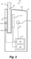
- FIG 3 shows a cross-sectional view of an example of an apparatus 100 as shown in Figure 1 .
- the apparatus 100 has a receptacle, or heating chamber 112 which is configured to receive the article 102 to be heated.
- the heating chamber 112 is generally in the form of a hollow cylindrical tube into which an article 102 comprising aerosolisable medium is inserted for heating in use.
- an article 102 comprising aerosolisable medium has been inserted into the heating chamber 112.
- the article 102 in this example is an elongate cylindrical rod, although the article 102 may take any suitable shape.
- an end of the article 102 projects out of the apparatus 100 through the opening 106 of the housing 104 such that user may inhale the aerosol through the article 102 in use.
- the end of the article 102 projecting from the apparatus 100 may include a filter material.
- the article 102 is fully received within the heating chamber 112 such that it does not project out of the apparatus 100.
- the user may inhale the aerosol directly from the opening 106, or via a mouthpiece which may be connected to the housing 102 around the opening 106.
- the apparatus 100 comprises one or more aerosol generating elements.
- the aerosol generating elements are in the form of a heater arrangement 120 arranged to heat the article 102 located within the chamber 112.
- the heater arrangement 120 comprises resistive heating elements that heat up when an electric current is applied to them.
- the heater arrangement 120 may comprise a susceptor material that is heated via induction heating.
- the apparatus 100 also comprises one or more induction elements which generate a varying magnetic field that penetrate the heater arrangement 120.
- the heater arrangement may be located internally or externally of the heating chamber 112.
- the heater arrangement may comprise a thin film heater that is wrapped around an external surface of the heating chamber 112.
- the heater arrangement 120 may be formed as a single heater or may be formed of a plurality of heaters aligned along the longitudinal axis of the heating chamber 112.
- the heating chamber 112 may be annular or tubular, or at least part-annular or part-tubular around its circumference.
- the heating chamber 112 is defined by a stainless steel support tube.
- the heating chamber 112 is dimensioned so that substantially the whole of the aerosolisable medium in the article 102 is located within the heating chamber 112, in use, so that substantially the whole of the aerosolisable medium may be heated.
- the heater arrangement 120 may include a susceptor that is located on or in the article 102, wherein the susceptor material is heatable via a varying magnetic field generated by the apparatus 100.
- the heating chamber 112 may be arranged so that selected zones of the aerosolisable medium can be independently heated, for example in turn (over time) or together (simultaneously), as desired.
- the apparatus 100 includes an electronics compartment 114 that houses electrical control circuitry or controller 116 and/or a power source 118, such as a battery. In other examples, a dedicated electronics compartment may not be provided and the controller 116 and power source 118 are located generally within the apparatus 100.
- the electrical control circuitry or controller 116 may include a microprocessor arrangement, configured and arranged to control the heating of the aerosolisable medium as discussed further below.
- the apparatus 100 includes a sensor arrangement comprising a first sensor 122a, and a second sensor 122b configured to monitor for the presence of a first marker (such as a reference marker) of the article 102 and sense, read or otherwise interrogate a second marker comprising indicia or identification information of the article 102, as discussed further below.
- the controller 116 is configured to receive one or more inputs/signals from the sensor arrangement 122a, 122b. The controller 116 may also receive a signal from the control element 110 and activate the heater arrangement 120 in response to the received signal and the received inputs. Electronic elements within the apparatus 100 may be electrically connected via one or more connecting elements 124, shown depicted as dashed lines.
- the power source 118 may be, for example, a battery, such as a rechargeable battery or a non-rechargeable battery.
- suitable batteries include, for example, a lithium-ion battery, a nickel battery (such as a nickel-cadmium battery), an alkaline battery and/or the like.
- the battery is electrically coupled to the one or more heaters to supply electrical power when required and under control of the controller 116 to heat the aerosolisable medium without causing the aerosolisable medium to combust. Locating the power source 118 adjacent to the heater arrangement 120 means that a physically large power source 118 may be used without causing the apparatus 100 as a whole to be unduly lengthy. As will be understood, in general a physically large power source 118 has a higher capacity (that is, the total electrical energy that can be supplied, often measured in Amp-hours or the like) and thus the battery life for the apparatus 100 can be longer.
- the apparatus 100 It is sometimes desirable for the apparatus 100 to be able to operate in a power saving mode when a user is not using the apparatus 100 as this will reduce power consumption and prolong battery life. It is also desirable for the apparatus to be able to identify or recognise the particular article 102 that has been introduced into the apparatus 100, without further input from the user. For example, the apparatus 100, including, in particular, the heating control provided by the controller 116, will often be optimised for a particular arrangement of the article 102 (e.g. one or more of size, shape, particular smokable material, etc.). It would be undesirable for the apparatus 100 to be used with an aerosol medium or an article 102 having different characteristics.
- the apparatus 100 can identify or recognise the particular article 102, or at least the general type of article 102, that has been introduced into the apparatus 100, this can help eliminate or at least reduce counterfeit or other non-genuine articles 102 being used with the apparatus 100.
- the sensor arrangement 122a, 122b is configured to operate in a first mode in which the sensor arrangement 122a, 122b monitors non-continuously for the presence of a first marker of the article 102, and a second mode, following the detection of said first marker, wherein the sensor arrangement 122a, 122b is configured to sense the second marker comprising identification information of the article 102.
- the sensor arrangement 122a, 122b comprises a first sensor 122a and a second sensor 122b that are spaced apart from each other at approximately the same distance as the first marker and the second marker.
- the sensor arrangement 122a, 122b may provide one or more inputs to the controller 116, based on the sensed marker arrangement.
- the controller 116 may determine a parameter or characteristic of the article 102, such as whether the article 102 is a genuine article, based on the received one or more inputs. In one example, this determination is based on the characteristics of the input(s).
- the first marker may produce a first input having a characteristic (e.g., a magnitude) which is an expected characteristic corresponding to a genuine article 102 or to a type of the aerosolisable medium of the article 102.
- the determination may be made on the presence (or absence) of the input(s), e.g., if a first input is received but a second input is not, the article 102 may be determined as not genuine.
- the controller 116 may activate the heater arrangement 120 depending on the determined parameter of the article 102.
- the apparatus 100 is therefore provided with means of detecting whether the article 102 is a genuine product or not and may alter the operation of the apparatus 100 accordingly, for example, by preventing supply of power to the heater arrangement 120 if a non-genuine article is detected. Preventing use of the apparatus 100 when a non-genuine article is inserted into the apparatus 100 would reduce the likelihood of consumers having a poor experience due to the use of illicit consumables.
- the controller 116 is able to determine a parameter of the article 102 based on the received one or more inputs from the sensor arrangement 122a, 122b and tailor the heat profile provided by the heater arrangement 120 based on the determined parameter.
- the heater arrangement 120 of the apparatus 100 may be configured to provide a first heating profile if the identification information of the article 102 has a first characteristic (e.g., by the controller 116 controlling the supply of power) and the heater arrangement 120 is configured to provide a second heating profile if the identification information of the article 102 has a second characteristic different from the first characteristic.
- the apparatus 100 may be able to determine whether the consumable is a solid or a non-solid consumable and adjust the heating profile accordingly.
- the apparatus 100 may be able to distinguish between different blends of tobacco in the article 102 and tailor the heating profile accordingly to provide an optimised heating profile for the specific blend of tobacco that has been inserted into the apparatus 100.
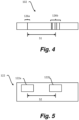
- Figure 4 shows a schematic longitudinal side view of an example of an article 102 comprising aerosolisable medium for use with the apparatus 100.
- the article 102 also comprises a filter arrangement (not shown) in addition to the aerosolisable medium.
- the article 102 also comprises a marker arrangement 126 that is configured to be sensed by the sensor arrangement 122a, 122b of the apparatus 100.
- the marker arrangement 126 includes a first marker 126a and a second marker 126b comprising identification information.
- the first marker 126a is configured to be sensed by the sensor arrangement 122a, 122b to indicate the presence of the article 102.
- the first marker 126a may be made up of one or more marker elements, as described below.
- the second marker 126b may be made up of one or more marker elements and represents encoded information indicative of a parameter or characteristic of the article 102.
- the parameter may indicate the maker of the article 102, such that the article 102 can be confirmed as genuine.
- the parameter may indicate the type of aerosolisable medium in the article 102, such as whether the aerosolisable medium is in the form of a solid, liquid or gel.
- the parameter may also be indicative of a variant of the aerosolisable medium, such as whether the aerosolisable medium comprises Burley tobacco or Virginia tobacco.
- the parameter may indicate a heating profile that should be used to heat the article 102.
- the parameter may indicate other characteristics of the article 102. Providing a second marker 126b allows the apparatus 100 to provide a tailored experience for the user based on the identification information of the article 102.
- the marker arrangement 126 may comprise an optical characteristic, for example, in Figure 4 , the first marker 126a is a marker element in the form of a single line on the outside of the article 102 and the second marker 126b comprises marker elements in the form of a plurality of lines on the outside of the article 102.
- the lines are shown as being uniform width, but in other examples, the width of the lines may be varied.
- the second marker 126b is indicative of an encoded parameter associated with the article 102.
- the one or more marker elements may extend part of the way around the perimeter or circumference of the article 102 or all of the way around the perimeter of the article 102.
- the sensor arrangement 122a, 122b configured to sense the marker arrangement 126 may be arranged at a specific location within the apparatus 100.
- the sensor arrangement 122a, 122b may be arranged adjacent to one side of the chamber 112 and may have a limited detection range. Providing marker elements that extend all of the way around the perimeter of the article 102 facilitates the sensing of the marker arrangement 126 by the sensor arrangement 122a, 122b, irrespective of the particular orientation of the article 102 within the apparatus 100.
- the marker arrangement 126 may be formed in a number of different ways, and be formed of a number of different materials, depending on the particular sensor arrangement 122a, 122b, of the apparatus 100 with which the article 102 is intended to be used.
- the marker arrangement 126 may comprise optical features such as lines, gaps or notches, surface roughness, and/or reflective material.
- the second marker 126b may comprise optical features such as a barcode or a QR code.
- the first sensor 122a and the second sensor 122b are spaced from each other by approximately the same distance as the predetermined distance of the first marker 126a and the second marker, such that S1 is approximately equal to S2.
- the first sensor 122a and the second sensor 122b may be spaced apart from each other by any suitable distance within the apparatus 100. In one example, the first sensor 122a and the second sensor 122b are spaced from each other by less than 70mm, more preferably less than 50mm, more preferably less than 30mm, more preferably less than 25, or more preferably less than 20mm.
- the second sensor 122b may not be able to read the identification information of the second marker 126b.
- matching the spacing between the first sensor 122a and the second sensor 122b and the first marker 126a and the second marker 126b provides an authenticity check of the article 102 and the apparatus 100 may be prevented from operating if the spacing does not match.
- the first sensor 122a has a first sense region in which the first sensor 122a is able to sense the first marker 126a and the second sensor 122b has a second sense region in which the second sensor 122b is able to sense the second marker 126b.
- the first and second sensors 122a, 122b are spaced from each other such that a point in the first sense region and a point in the second sense region are spaced apart from each other by the predetermined distance. This arrangement provides some tolerance for the spacing of the first marker 126a and 126b.
- the first sense region defines a first distance along the longitudinal axis of the chamber 112 and the second sense region defines a second distance along the longitudinal axis of the chamber 112.
- the first and second sensors 122a, 122b are spaced from each other such by an amount between the predetermined distance minus the first and second longitudinal distances and the predetermined distance plus the first and second longitudinal distances. Again, this arrangement allows for some tolerance of the spacing of the spacing of the first marker 126a and 126b.
- the sense regions are defined based on the operational tolerances of the sensors. For example, the sense regions may be defined based on the field of view of an optical sensor or the range of an RFID sensor, for example, 20mm.
- This tolerance allows for the positioning of markers 126a and 126b on the consumable itself to vary between articles. For example, it may be difficult during production to ensure that the markers 126a, 126b are always in the exact same position on the consumable but the relative spacing between the markers 126a, 126b can be produced with high accuracy. By providing the sensors with a tolerance, the spacing between markers 126a, 126b can still be used for determining authenticity and/or other information of the article with a simpler production process.
- the relative spacing between the markers is combined with further information read from the marker itself, such as barcode or 2-D barcode.
- the combination of the spacing and information read from the markers may provide a check on authenticity, with only some combinations valid. For example, a particular marker may be associated with a single relative positioning of the first and second marker. If the spacing does not substantially equal the spacing associated with the marker then the article may be determined as counterfeit.
- the first sensor may indicate a position of the first marker within its sensed region as a baseline or datum for use by the second sensor.
- the second sensor may determine a position of the second marker within its sensing region relative to the baseline or datum provided by the first sensor, allowing the relative position of the markers to be determined.
- the first marker 126a may be configured to be sensed by the sensor arrangement 122a, 122b to determine whether the article 102 is in the vicinity of the first sensor 122a.
- the sensor arrangement 122a, 122b is configured to operate in a first mode when monitoring for the presence of the first marker 122a. In the first mode, the sensor arrangement 122a, 122b is not configured to detect the second marker 126b and so the apparatus may operate at a relatively low power.
- the sensor arrangement 122a, 122b detects the presence of the first marker 122a of the article, it switches to a second mode in which the sensor arrangement 122a, 122b is configured to sense the second marker 122b.
- the sensor arrangement 122a, 122b in a first mode, is configured to non-continuously monitor for the presence of the first marker 126a. In one example, the sensor arrangement 122a, 122b periodically monitors for the presence of the first marker 126a at regular intervals. However, in other examples, the sensor arrangement 122a, 122b monitors for the presence of the first marker 126a at irregular intervals. In one example, the sensor arrangement 122a, 122b is configured to monitor for the presence of the first marker 126a with a duty ratio of less than or equal to 10%. In one example, the sensor arrangement 122a, 122b is configured to monitor for the presence of the first marker 126a for 1 millisecond in every 10 milliseconds.
- Non-continuous monitoring for the presence of the first marker 126a is more energy efficient compared with continuously monitoring for the presence of the reference marker 126a as is does not require a constant source of power.
- the sensor arrangement 122a, 122b may be configured to begin monitoring for the presence of the first marker 126a in response to a user input, e.g., such as switching on the apparatus 100 (e.g., via a user activated button on the outside of the apparatus 100).
- the sensor arrangement 122a, 122b may be switched off for a predetermined time (i.e., no further sensing occurs for the predetermined time). These options may further reduce energy consumption.
- the sensor arrangement 122a, 122b may provide a first input to the controller 116 to indicate that an article 102 comprising a first marker 126a has been detected.
- the controller 116 may be configured to signal the sensor arrangement 122a, 122b to operate in a second mode to sense the second marker 126b.
- the sensor arrangement 122a, 122b may be configured to sense the first marker 126a and the second marker 126b simultaneously.
- the second marker 126b includes marker elements that are configured to be sensed by the sensor arrangement 122a, 122b to enable a parameter associated with the article 102 to be determined by the controller 116.
- the second marker comprising identification information 126b includes four marker elements in the form of lines. The marker elements are spaced form each other at varying distances.
- the arrangement of the marker elements is indicative of a parameter of the article 102, as described in more detail below.
- the arrangement of the marker elements may be indicative of the article 102 being a genuine article 102 intended for use with the apparatus 100, or it could be indicative of the heating profile to be used with this article 102.
- the sensor arrangement 122a, 122b is configured to provide a second input indicative of the parameter of the article 102 to the controller 116.
- the marker arrangement 126 may be provided internally and/or externally of the article 102.
- the marker arrangement 126 may be literally “marked on” the article 102, such as by printing.
- the marker arrangement 126 may be provided in or on the article 102 by other techniques, such as being formed integrally with the article 102 during manufacture.
- the marker arrangement 126 may be formed of an electrically conductive material.
- the marker arrangement 126 may be, for example, a metallic component such as aluminium or a conductive ink or ferrous or non-ferrous coating.
- the ink may be printed onto tipping paper of the article 102, using for example a rotogravure printing method, screen printing, ink jet printing, or any other suitable process.
- capacitive sensing operates by effectively sensing a change in capacitance when the article 102 is located within the apparatus 100.
- a measure of the capacitance is obtained. If the capacitance meets one or more criteria, it may be decided that the article 102 is suitable for use with the apparatus 100, which can then proceed to operate as normal to heat the aerosolisable medium. Otherwise, if the capacitance does not meet the one or more criteria, it may be decided that the article 102 is not suitable for use with the apparatus 100, and the apparatus 100 does not function to heat the aerosolisable medium and/or may issue some warning message to the user.
- capacitive sensing may work by providing the apparatus 100 with (at least) one electrode which in effect provides one "plate” of a capacitor, with the other "plate” of the capacitor being provided by the electrically conducting marker arrangement 126 of the apparatus 100 mentioned above.
- the apparatus 100 may be provided with (at least) two electrodes, which in effect provide the pair of "plates" of a capacitor. When the article 102 is inserted into the apparatus 100, it is inserted between the two electrodes.
- the capacitance formed between the two electrodes of the apparatus 100 changes.
- a measure of this capacitance formed by the two electrodes of the apparatus 100 can be obtained, and then compared to one or more criteria to determine whether the apparatus 100 can then proceed to heat the article 102.
- the sensor arrangement 122a, 122b comprises at least two different sensing techniques, for example, the first sensor and the second sensor are configured to sense different properties.
- one sensor such as the first sensor 122a, may comprise an optical sensor and the other sensor, such as second sensor 122b, may comprise a non-optical sensor, such as a capacitive sensor.
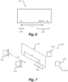
- Figure 6 shows a side view of an alternative example of an article 202 for use with an apparatus for heating aerosolisable medium.
- the marker arrangement 226 is in the form of a plurality of notches or holes formed in the article 202.
- the marker arrangement 226 in the example of Figure 6 comprises a first marker 226a and a second marker 226b.
- the first marker 226a comprises a single marker element and the second marker 226b comprises marker elements spaced at a varying distance from each other.
- the first marker 226a and the second marker 226b are spaced apart by a distance S1.
- Figure 7 shows an illustrative example of an optical sensor arrangement 222a, 222b.
- the sensor arrangement 222a, 222b comprises a first sensor 222a in the form of a first light source 232a, such as an LED, and first light receiver 234a, such as light sensor, and a second sensor 222b in the form of a second light source 232b and a second light receiver 234b.
- the light receivers 234a, 234b are configured to receive light from the light sources 232a, 232b.
- the article 202 In use, as the article 202 is located next to the sensors arrangement 222a, 222b in between the light sources 232a, 232b and the receivers 234a, 234b, the article 202 blocks the light and prevents it from being received at the receivers 234a, 234b. In other examples, the article 202 reduces the amount of light being received at the receivers 234a, 234b, rather than blocking it. However, light is not blocked in the location of the marker elements in the form of a notches. Therefore, the quantity of light received at the receivers 234a, 234b will vary across the length of the article 202 depending on whether a notch is within the light path between the light sources 232a and the receivers 234 or not. In this example, the first sensor 222a of the sensor arrangement is spaced from the second sensor of the sensor arrangement 222b by a distance S2.
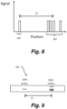
- Figure 8 shows an example of a signal generated by the sensor arrangement 222a, 222b.
- a first signal 240 is a representation of light received by the first light sensor 234a from the first light source 232a and the second signal 242 is a representation of light received by the second light sensor 234a from the second light source 232a.
- the position of the peaks of the first signal 240 is equivalent to the positioning of the first marker 226a on the article 202 and the position of the peaks of the second signal 242 is indicative of the arrangement of the second marker 226b.
- the distance between the centre point of the peaks of the first signal 240 and the peaks of the second signal 242 is S3, which is substantially equal to S1 and S2.
- the distance S2 between the first sensor 222a and the second sensor 222b is not substantially equal to the distance S1 between the first marker 226a and the second marker 226b, then part or all of one of the signals 240, 242 will be missing, which will be indicative of the article 202 not being genuine.
- the sensor arrangement 222a, 222b in a first mode, is configured to non-continuously monitor for the presence of the first marker 226a so power is not supplied to the light source 232b and light receiver 234b during the first mode.
- the first signal 240 shown in Figure 8 may be provided to the controller 216 as a first input, which determines whether the position and size of the first marker 226a indicates that the article 202 is genuine or not, for example, by using a look-up table.
- the controller 216 determines that the first marker 226a is indicative of the article 202 being genuine, then the sensor arrangement 222a, 222b will switch to a second mode wherein power is supplied to the to the light source 232b and light receiver 234b to enable the second sensor 222b to sense the second marker 226b.
- the second signal 242 shown in Figure 8 may be provided to the controller 216 as a second input.
- the controller 116 determines identification information of the article 202, for example, by using a look-up table.
- the second input is indicative of a parameter of the article 202 and so enables the controller 116 to determine the parameter of the article 202.
- the sensor arrangement 222a, 222b comprises two light sources 232a, 232b and two light receivers 234a, 234b.
- the optical sensor may comprise an array of light sources and an array of light sensors.
- the light source 232 and the light receiver 234 may be formed in a single element and light will be reflected back to the light source/receiver to indicate the position of the marker element.
- the sensor arrangement 122a, 122b, 222a, 222b is configured to sense the marker arrangement 126, 226 by measuring the reflection or surface roughness from the surface of the article 102, 202.
- the sensor arrangement 122a, 122b, 222a, 222b may be configured to sense and read the marker comprising identification information 126b in the form of a barcode or QR code.
- the sensor arrangement 122a, 122b, 222a, 222b may be configured to sense visible or invisible fluorescent material.
- the controller 116 may comprise pre-programmed information, such as a look-up table, that includes details of the various possible arrangements of the second marker 126b, 226b and what parameter is associated with each arrangement. Therefore, the controller 116 is able to determine the parameter associated with the article 102, 202.
- the controller 116 may be arranged so that it will only heat an article 102, 202 that it recognises, and will not operate in conjunction with an article 102, 202 that it does not recognise.
- the apparatus 100 may be arranged so that it provides some indication to the user that the article 102, 202 has not been recognised. This indication may be visual (for example a warning light, which may for example flash or be illuminated continuously for a period of time) and/or audible (for example a warning "beep" or the like).
- the apparatus 100 may be arranged so that, for example, it follows a first heating pattern when it recognises a first type of article 102, 202 and follows a second, different heating pattern when it recognises a second type of article 102, 202 (and optionally may provide yet further heating patterns for other types of article 102, 202).
- the heating patterns may differ in a number of ways, for example the rate of delivery of heat to the aerosolisable medium, the timing of various heating cycles, which part(s) of the aerosolisable medium are heated first, etc., etc. This enables the same apparatus 100 to be used with different basic types of article 102, 202 with minimal interaction required of the user.
- Figure 9 shows a schematic longitudinal side view of another example of an article 302 comprising aerosolisable medium for use with the apparatus 100.
- the article 302 comprises a marker arrangement 326a, 326b in the form of optical lines.
- the lines extend substantially along the longitudinal axis of the article 302, rather than substantially perpendicular to the longitudinal axis, as is shown in the example of the article 102 in Figure 4 .
- the marker arrangement 326 is split into a first marker 326a (such as a reference marker) and a second marker 326b.
- the first marker 326a and the second marker 326b are spaced by a distance S1.
- the second marker 326b includes four marker elements in the form of lines with a varied spacing therebetween.
- the spacing of the marker elements may be such as to create a defined start of the marker element and a defined end of the marker elements.
- the article 302 would need to make a full or partial rotation for all of the marker elements to be read by the one or more sensors 322a, 322b to determine the spacing of the marker elements.
- the article 102, 202, 302 may have a location feature that enables the consumable to be inserted into the apparatus 100 with a defined orientation.
- the article may comprise a protrusion or a cut-out feature that corresponds to a shape in the opening 106 of the apparatus 100.
- the article 102, 202, 302 may only be inserted into the apparatus 100 in a single orientation.
- the starting position would be known and as such there would be no requirement for the article 102, 202, 302 to be rotated by at least 360 degrees.
- the article 102, 202, 302 may have a predefined finger holds or orientation to align or feed into a device (ensuring the consumable is inserted in a predefined manner.
- the one or more sensors 122a, 122b may be arranged at a specific location within the apparatus 100.
- the sensor arrangement 122a, 122b may be arranged within the chamber 112 and may have a limited detection range.
- the marker arrangement 126 may be arranged at a specific location on, or within the article 102, 202, 302, and may occupy a certain area or volume of the article 102.
- Figure 10 shows an example of a flow diagram of an operation an aerosol generating apparatus 100.
- the apparatus 100 senses, at a first sensor 122a of a sensor arrangement, a first indicia 126a of an article 102 comprising aerosolisable medium.
- the apparatus 100 senses, at a second sensor 122b of the sensor arrangement, a second indicia of the article 100.
- the apparatus 100 operates the aerosol generating apparatus based on the first indicia and the second indicia.
- the controller 116 controls the operation of the one or more heaters 120 based on the parameter of said article, for example, if the controller determines that a counterfeit article has been inserted into the apparatus 100, then the heaters are not activated.
- the controller 116 may determine the type of aerosolisable medium within the article, such as solid, liquid or gel and tailor the heating profile accordingly.
- first and second sensors may be provided spaced at different predetermined distances.
- a first first sensor and a first second sensor may be spaced at one predetermined distance
- a second first sensor and second second sensor may be spaced at a different predetermined distance.
- These different predetermined distances may correspond to different articles 102 which may have markers spaced at different predetermined distances.
- the controller 116 may be configured to sense different articles 102 based upon which of the sensor groups detects input(s). This enables the controller 116 to distinguish between articles 102 based solely or additionally on which sensors detect an input.
- sensors of one 'group' may be used to define further groups of sensors - that is the first first sensor and the second second sensor may define their own group, and an input detected by these sensors signifies a different article to an input sensed by the first group or the second group.
- the article 102, 202, 302 may comprise one or more flavourants.
- flavourants and “flavourant” refer to materials which, where local regulations permit, may be used to create a desired taste or aroma in a product for adult consumers.
- extracts e.g., licorice, hydrangea, Japanese white bark magnolia leaf, chamomile, fenugreek, clove, menthol, Japanese mint, aniseed, cinnamon, herb, wintergreen, cherry, berry, peach, apple, Drambuie, bourbon, scotch, whiskey, spearmint, peppermint, lavender, cardamom, celery, cascarilla, nutmeg, sandalwood, bergamot, geranium, honey essence, rose oil, vanilla, lemon oil, orange oil, cassia, caraway, cognac, jasmine, ylang-ylang, sage, fennel, piment, ginger, anise, coriander, coffee, or a mint oil from any species of the genus Mentha), flavour enhancers, bitterness receptor site blockers, sensorial receptor site activators or stimulators, sugars and/or sugar substitutes (e.g., sucralose, acesulfame, cinnamon
Landscapes
- Physics & Mathematics (AREA)
- General Physics & Mathematics (AREA)
- Geophysics (AREA)
- Life Sciences & Earth Sciences (AREA)
- General Life Sciences & Earth Sciences (AREA)
- Engineering & Computer Science (AREA)
- Computer Vision & Pattern Recognition (AREA)
- Artificial Intelligence (AREA)
- Theoretical Computer Science (AREA)
- Control Of Vending Devices And Auxiliary Devices For Vending Devices (AREA)
- Geophysics And Detection Of Objects (AREA)
- Infusion, Injection, And Reservoir Apparatuses (AREA)
- Details Of Rigid Or Semi-Rigid Containers (AREA)
- Length Measuring Devices With Unspecified Measuring Means (AREA)
- Sampling And Sample Adjustment (AREA)
- Investigating Or Analyzing Materials Using Thermal Means (AREA)
- Medicinal Preparation (AREA)
- Containers And Packaging Bodies Having A Special Means To Remove Contents (AREA)
Claims (14)
- Einrichtung (100) zum Erzeugen eines Aerosols aus einem aerosolisierbaren Medium, wobei das Aerosol durch Erhitzen des aerosolisierbaren Mediums erzeugt wird, wobei die Einrichtung (100) umfasst:ein Gehäuse (104);eine Kammer (112) zum Aufnehmen eines Artikels (102), wobei der Artikel (102) Folgendes umfasst: das aerosolisierbare Medium; und eine Markierungsanordnung (126a, 126b), die eine erste Markierung (126a) und eine zweite Markierung (126b) umfasst, die um eine vorbestimmte Distanz voneinander beabstandet sind; undeine Sensoranordnung (122a, 122b), die einen ersten Sensor (122a) zum Erfassen der ersten Markierung (126a) und einen zweiten Sensor (122b) zum Erfassen der zweiten Markierung (126b) umfasst, wobei:der erste Sensor (122a) und der zweite Sensor (122b) ungefähr um die gleiche Distanz wie die vorbestimmte Distanz voneinander beabstandet sind;der erste Sensor (122a) einen ersten Erfassungsbereich aufweist, in dem der erste Sensor (122a) die erste Markierung (126a) erfassen kann;der zweite Sensor (122b) einen zweiten Erfassungsbereich aufweist, in dem der zweite Sensor (122b) die zweite Markierung (126b) erfassen kann; undder erste und der zweite Sensor (122a, 122b) so voneinander beabstandet sind, dass ein Punkt im ersten Erfassungsbereich und ein Punkt im zweiten Erfassungsbereich um die vorbestimmte Distanz voneinander beabstandet sind
- Einrichtung (100) nach Anspruch 1, wobei die Sensoranordnung (122a, 122b) dazu konfiguriert ist, eine relative Positionierung der ersten Markierung (126a) und der zweiten Markierung (126b) zu bestimmen.
- Einrichtung (100) nach Anspruch 1 oder 2, wobei die Kammer (112) eine Längsachse definiert und der erste Sensor (122a) und der zweite Sensor (122b) entlang einer Richtung angeordnet sind, die im Wesentlichen parallel zur Längsachse der Kammer (112) verläuft.
- Einrichtung (100) nach Anspruch 1, 2 oder 3, wobei:der erste Erfassungsbereich eine erste Distanz entlang einer Längsrichtung der Kammer (112) definiert;der zweite Erfassungsbereich eine zweite Distanz entlang der Längsrichtung der Kammer (112) definiert undder erste und der zweite Sensor (122a, 122b) um einen Betrag zwischen der vorbestimmten Distanz minus der ersten und zweiten Längsdistanz und der vorbestimmten Distanz plus der ersten und zweiten Längsdistanz voneinander beabstandet sind.
- Einrichtung (100) nach einem der Ansprüche 1 bis 4, wobei die Einrichtung (100) ein oder mehrere Aerosolerzeugungselemente umfasst, die so konfiguriert sind, dass sie auf der Grundlage einer erfassten Identifikationsinformation des Artikels (102) aktiviert werden,wobei optional das eine oder die mehreren Aerosolerzeugungselemente eine Heizanordnung (120) umfassen,wobei optional die Heizanordnung (120) dazu konfiguriert ist, ein erstes Heizprofil bereitzustellen, wenn die Identifikationsinformationen eine erste Charakteristik aufweisen, und die Heizanordnung (120) dazu konfiguriert ist, ein zweites Heizprofil bereitzustellen, wenn die Identifikationsinformationen eine zweite Charakteristik aufweisen, die sich von der ersten Charakteristik unterscheidet.
- Einrichtung (100) nach einem der Ansprüche 1 bis 5, wobei die Sensoranordnung (122a, 122b) einen optischen Sensor umfasst.
- Einrichtung (100) nach einem der Ansprüche 1 bis 6, wobei die Sensoranordnung (122a, 122b) einen kapazitiven Sensor umfasst.
- Einrichtung (100) nach einem der Ansprüche 1 bis 7, wobei der erste Sensor (122a) und der zweite Sensor (122b) unterschiedliche Sensortypen sind.
- Einrichtung (100) nach einem der Ansprüche 1 bis 8, wobei die vorbestimmte Distanz weniger als 70 mm, weniger als 50 mm, weniger als 30 mm, weniger als 25 mm oder weniger als 20 mm beträgt.
- Aerosolbereitstellungssystem, das die Einrichtung (100) nach einem der Ansprüche 1 bis 9 und einen Artikel (102) zur Verwendung mit der Einrichtung (100) umfasst, wobei der Artikel (102) Folgendes umfasst:ein aerosolisierbares Medium; undeine Markierungsanordnung (126a, 126b), die eine erste Markierung (126a) und eine zweite Markierung (126b) umfasst, die Identifikationsinformationen umfassen, wobei die erste Markierung (126a) und die zweite Markierung (126b) um eine vorbestimmte Distanz voneinander beabstandet sind.
- Aerosolbereitstellungssystem (102) nach Anspruch 10, wobei die Markierungsanordnung (126a, 126b) optische Merkmale umfasst,
wobei optional die Markierungsanordnung (126a, 126b) elektrisch leitfähige Merkmale umfasst. - Aerosolbereitstellungssystem (102) nach Anspruch 10 oder 11, wobei der Artikel (102) eine Einführachse definiert und die Markierungsanordnung (126a, 126b) entlang einer Richtung angeordnet ist, die im Wesentlichen parallel zur Einführachse ist.
- Aerosolbereitstellungssystem (102) nach Anspruch 10 oder 11, wobei die Markierungsanordnung (126a, 126b) um zumindest einen Teil eines Umfangs des Artikels (100) herum angeordnet ist.
- Verfahren zum Betreiben einer Aerosolerzeugungseinrichtung (100) nach einem der Ansprüche 1 bis 9, wobei das Verfahren umfasst:Erfassen eines ersten Kennzeichens (126a) eines Artikels (102), der ein aerosolisierbares Medium umfasst, am ersten Sensor (122a) der Sensoranordnung (122a, 122b);Erfassen eines zweiten Kennzeichens (126b) des Artikels (102) am zweiten Sensor (122b) der Sensoranordnung (122a, 122b), der vom ersten Sensor (122a) um eine vorbestimmte Distanz beabstandet ist;Bestimmen einer Distanz zwischen dem ersten Kennzeichen (126a) und dem zweiten Kennzeichen (126b); undBetreiben der Aerosolerzeugungseinrichtung (100) basierend zumindest auf der Distanz zwischen dem ersten Kennzeichen (126a) und dem zweiten Kennzeichen (126b).
Priority Applications (1)
| Application Number | Priority Date | Filing Date | Title |
|---|---|---|---|
| EP24208996.9A EP4494682A3 (de) | 2018-03-29 | 2019-03-27 | Vorrichtung zur erzeugung von aerosol aus einem aerosolfähigen medium, artikel aus einem aerosolfähigen medium und verfahren zum betrieb einer aerosolerzeugungsvorrichtung |
Applications Claiming Priority (2)
| Application Number | Priority Date | Filing Date | Title |
|---|---|---|---|
| GBGB1805268.8A GB201805268D0 (en) | 2018-03-29 | 2018-03-29 | Apaaratus for generating aerosol from an aerosolisable medium, an article of aerosolisable medium and a method of operating an aerosol generating apparatus |
| PCT/EP2019/057784 WO2019185749A1 (en) | 2018-03-29 | 2019-03-27 | Apparatus for generating aerosol from an aerosolisable medium, an article of aerosolisable medium and a method of operating an aerosol generating apparatus |
Related Child Applications (2)
| Application Number | Title | Priority Date | Filing Date |
|---|---|---|---|
| EP24208996.9A Division EP4494682A3 (de) | 2018-03-29 | 2019-03-27 | Vorrichtung zur erzeugung von aerosol aus einem aerosolfähigen medium, artikel aus einem aerosolfähigen medium und verfahren zum betrieb einer aerosolerzeugungsvorrichtung |
| EP24208996.9A Division-Into EP4494682A3 (de) | 2018-03-29 | 2019-03-27 | Vorrichtung zur erzeugung von aerosol aus einem aerosolfähigen medium, artikel aus einem aerosolfähigen medium und verfahren zum betrieb einer aerosolerzeugungsvorrichtung |
Publications (2)
| Publication Number | Publication Date |
|---|---|
| EP3773033A1 EP3773033A1 (de) | 2021-02-17 |
| EP3773033B1 true EP3773033B1 (de) | 2024-12-04 |
Family
ID=62142123
Family Applications (2)
| Application Number | Title | Priority Date | Filing Date |
|---|---|---|---|
| EP19718580.4A Active EP3773033B1 (de) | 2018-03-29 | 2019-03-27 | Vorrichtung zum erzeugen von aerosol aus einem aerosolisierbaren medium, ein artikel aus einem aerosolisierbaren medium und ein verfahren zum betreiben einer aerosolerzeugungsvorrichtung |
| EP24208996.9A Pending EP4494682A3 (de) | 2018-03-29 | 2019-03-27 | Vorrichtung zur erzeugung von aerosol aus einem aerosolfähigen medium, artikel aus einem aerosolfähigen medium und verfahren zum betrieb einer aerosolerzeugungsvorrichtung |
Family Applications After (1)
| Application Number | Title | Priority Date | Filing Date |
|---|---|---|---|
| EP24208996.9A Pending EP4494682A3 (de) | 2018-03-29 | 2019-03-27 | Vorrichtung zur erzeugung von aerosol aus einem aerosolfähigen medium, artikel aus einem aerosolfähigen medium und verfahren zum betrieb einer aerosolerzeugungsvorrichtung |
Country Status (10)
| Country | Link |
|---|---|
| US (3) | US11974608B2 (de) |
| EP (2) | EP3773033B1 (de) |
| JP (3) | JP2021523683A (de) |
| KR (3) | KR20200122392A (de) |
| BR (1) | BR112020020020A2 (de) |
| CA (1) | CA3095121C (de) |
| GB (1) | GB201805268D0 (de) |
| PL (1) | PL3773033T3 (de) |
| RU (1) | RU2766175C1 (de) |
| WO (1) | WO2019185749A1 (de) |
Families Citing this family (33)
| Publication number | Priority date | Publication date | Assignee | Title |
|---|---|---|---|---|
| GB201805268D0 (en) * | 2018-03-29 | 2018-05-16 | Nicoventures Trading Ltd | Apaaratus for generating aerosol from an aerosolisable medium, an article of aerosolisable medium and a method of operating an aerosol generating apparatus |
| GB201901066D0 (en) * | 2019-01-25 | 2019-03-13 | Nicoventures Trading Ltd | Aerosol generating apparatus, aerosol generating article and method of determining data associated with an aerosol generating article |
| US11497254B1 (en) * | 2019-03-11 | 2022-11-15 | Rasheed Ali | System and method for authenticating an electronic vaping delivery unit |
| CN113068397B (zh) * | 2019-10-15 | 2022-12-09 | 深圳市汇顶科技股份有限公司 | 烟具和烟弹 |
| WO2021084034A1 (en) * | 2019-10-30 | 2021-05-06 | Jt International Sa | Aerosol generation device with low power mode |
| EP4076032A1 (de) | 2019-12-20 | 2022-10-26 | JT International SA | Aerosolerzeugungsartikel mit optischem code und system, das diesen artikel umfasst |
| KR20220119612A (ko) * | 2019-12-20 | 2022-08-30 | 제이티 인터내셔널 소시에떼 아노님 | 에어로졸 발생 물품을 인증하기 위한 도파관 배치를 갖는 에어로졸 발생 시스템 및 장치 |
| US12349737B2 (en) | 2019-12-20 | 2025-07-08 | Jt International S.A. | Aerosol generation device with optical code detector |
| JP7348313B2 (ja) * | 2020-01-21 | 2023-09-20 | 日本たばこ産業株式会社 | エアロゾル生成装置の電源ユニット及びカートリッジ、並びにカートリッジの種別を判定する方法 |
| JP7693665B2 (ja) * | 2020-02-26 | 2025-06-17 | ジェイティー インターナショナル エスエイ | その内部照射によってエアロゾル発生物品を認証するための手段を含む非燃焼加熱式エアロゾル発生装置 |
| WO2021249833A1 (en) | 2020-06-12 | 2021-12-16 | Jt International S.A. | Method and system for identifying aerosol-generating articles |
| EP4164437A1 (de) * | 2020-06-12 | 2023-04-19 | JT International S.A. | Verfahren und system zur identifizierung von rauchartikeln |
| CN114073336A (zh) * | 2020-08-11 | 2022-02-22 | 深圳市合元科技有限公司 | 气溶胶生成装置及其方法、系统 |
| WO2022063920A1 (en) * | 2020-09-28 | 2022-03-31 | Jt International S.A. | An electrically operated smoking device including a system for identifying smoking articles comprising an indicium |
| KR102640559B1 (ko) * | 2020-10-30 | 2024-02-23 | 주식회사 케이티앤지 | 에어로졸 시뮬레이션 장치 및 그 방법 |
| KR102640560B1 (ko) * | 2020-10-30 | 2024-02-23 | 주식회사 케이티앤지 | 에어로졸 시뮬레이션 장치 및 그 방법 |
| KR102640561B1 (ko) * | 2020-10-30 | 2024-02-23 | 주식회사 케이티앤지 | 에어로졸 시뮬레이션 장치 및 그 방법 |
| KR20220069614A (ko) * | 2020-11-20 | 2022-05-27 | 주식회사 케이티앤지 | 에어로졸 생성 장치 및 에어로졸 생성 물품 |
| KR102533269B1 (ko) * | 2020-12-21 | 2023-05-15 | 주식회사 케이티앤지 | 에어로졸 생성장치 |
| KR102457799B1 (ko) * | 2020-12-21 | 2022-10-20 | 주식회사 케이티앤지 | 에어로졸 생성장치 |
| KR102457798B1 (ko) * | 2020-12-21 | 2022-10-20 | 주식회사 케이티앤지 | 에어로졸 생성장치 |
| KR102457796B1 (ko) * | 2020-12-21 | 2022-10-20 | 주식회사 케이티앤지 | 에어로졸 생성장치 |
| KR102522127B1 (ko) * | 2020-12-24 | 2023-04-14 | 주식회사 케이티앤지 | 에어로졸 생성 장치용 히터 조립체 및 이를 포함하는 에어로졸 생성 장치 |
| GB202103376D0 (en) * | 2021-03-11 | 2021-04-28 | Nicoventures Trading Ltd | Aerosol provision systems |
| KR102834855B1 (ko) * | 2021-05-21 | 2025-07-18 | 주식회사 케이티앤지 | 에어로졸 생성장치 |
| EP4340661B1 (de) | 2021-05-21 | 2025-02-26 | JT International SA | Aerosolerzeugungsvorrichtung |
| KR20240018570A (ko) * | 2021-07-09 | 2024-02-13 | 니뽄 다바코 산교 가부시키가이샤 | 에어로졸 생성 장치의 전원 유닛 |
| WO2023026322A1 (ja) * | 2021-08-23 | 2023-03-02 | 日本たばこ産業株式会社 | エアロゾル生成システム |
| WO2023075558A1 (en) * | 2021-11-01 | 2023-05-04 | Kt&G Corporation | Aerosol generating device and system including the same |
| KR20240117629A (ko) * | 2021-12-28 | 2024-08-01 | 니뽄 다바코 산교 가부시키가이샤 | 비연소형 향미 흡인기 |
| JP2025515033A (ja) * | 2022-05-03 | 2025-05-13 | ジェイティー インターナショナル エスエイ | 熱拡散層を備えるエアロゾル発生デバイス |
| CN120282721A (zh) * | 2022-12-20 | 2025-07-08 | 韩国烟草人参公社 | 气溶胶生成装置 |
| CN115736379A (zh) * | 2022-12-29 | 2023-03-07 | 思摩尔国际控股有限公司 | 一种带状雾化介质及气溶胶生成装置 |
Family Cites Families (51)
| Publication number | Priority date | Publication date | Assignee | Title |
|---|---|---|---|---|
| US5082365A (en) | 1989-12-28 | 1992-01-21 | Kuzmick Kenneth F | Remote identification and speed determination system |
| JPH04271487A (ja) | 1991-02-26 | 1992-09-28 | Fujikura Ltd | バーコード |
| US5388594A (en) | 1991-03-11 | 1995-02-14 | Philip Morris Incorporated | Electrical smoking system for delivering flavors and method for making same |
| DE4328243C1 (de) | 1993-08-19 | 1995-03-09 | Sven Mielordt | Rauch- oder Inhalationsvorrichtung |
| CR4906A (es) | 1993-09-10 | 1994-09-09 | Philip Morris Prod | Sistema electrico de fumar para distribuir sabores y metodopara su fabricacion |
| JPH08130613A (ja) | 1994-10-28 | 1996-05-21 | Sony Tektronix Corp | スキャナ装置 |
| US5934289A (en) * | 1996-10-22 | 1999-08-10 | Philip Morris Incorporated | Electronic smoking system |
| KR100289448B1 (ko) | 1997-07-23 | 2001-05-02 | 미즈노 마사루 | 향미발생장치 |
| US5967148A (en) | 1997-10-16 | 1999-10-19 | Philip Morris Incorporated | Lighter actuation system |
| US6053176A (en) | 1999-02-23 | 2000-04-25 | Philip Morris Incorporated | Heater and method for efficiently generating an aerosol from an indexing substrate |
| WO2003056949A1 (fr) | 2001-12-28 | 2003-07-17 | Japan Tobacco Inc. | Article pour fumeur |
| EP1474196B1 (de) * | 2002-01-15 | 2016-08-17 | Novartis AG | Verfahren und systeme zum bedienen eines aerosol-erzeugers |
| CA2540715A1 (en) * | 2003-10-03 | 2005-04-14 | Novo Nordisk A/S | Container comprising code information elements |
| JP4518542B2 (ja) | 2004-03-29 | 2010-08-04 | 独立行政法人産業技術総合研究所 | 植物発芽抑制剤及びその使用方法 |
| CN2719043Y (zh) | 2004-04-14 | 2005-08-24 | 韩力 | 雾化电子烟 |
| NL1027533C2 (nl) | 2004-11-17 | 2006-05-18 | Berten Beheer B V N | Inhaleerinrichting en bijbehorende verwarmingsinrichting en verpakking. |
| US7233389B2 (en) | 2004-12-03 | 2007-06-19 | Omnitek Partners, Llc | System and method for the measurement of the velocity and acceleration of objects |
| JP4534056B2 (ja) | 2005-02-01 | 2010-09-01 | 日本電産サンキョー株式会社 | 情報記録媒体及び情報読取装置 |
| ITME20050008A1 (it) | 2005-12-09 | 2006-03-10 | Brumil Internat Srl | Sistema che consente rilascio di nicotina per aspirazione, destinato ai fumatori di sigarette. |
| CN201067079Y (zh) | 2006-05-16 | 2008-06-04 | 韩力 | 仿真气溶胶吸入器 |
| JP5154308B2 (ja) | 2008-05-27 | 2013-02-27 | パナソニック株式会社 | 照明器具 |
| EP2201850A1 (de) | 2008-12-24 | 2010-06-30 | Philip Morris Products S.A. | Gegenstand, der Kennungsdaten beinhaltet, zur Verwendung in einem elektrisch beheizten Rauchsystem |
| JP5896747B2 (ja) * | 2009-02-13 | 2016-03-30 | ノボ・ノルデイスク・エー/エス | 医療用デバイス及びカートリッジ |
| JP2010020790A (ja) | 2009-09-18 | 2010-01-28 | Win Tec:Kk | カード印刷装置 |
| IT1398439B1 (it) | 2010-02-02 | 2013-02-22 | Danieli Automation Spa | Dispositivo per la misura di velocita' di prodotti in movimento, in particolare prodotti laminati metallici in una linea di laminazione, e relativo procedimento |
| US9152829B2 (en) * | 2010-08-19 | 2015-10-06 | Sanofi-Aventis Deutschland Gmbh | Method and system for determining information related to a drug reservoir using an electronic sensor |
| RU103281U1 (ru) | 2010-12-27 | 2011-04-10 | Общество с ограниченной ответственностью "ПромКапитал" | Электронная сигарета |
| US9078473B2 (en) | 2011-08-09 | 2015-07-14 | R.J. Reynolds Tobacco Company | Smoking articles and use thereof for yielding inhalation materials |
| GB201215282D0 (en) | 2012-08-28 | 2012-10-10 | Kind Consumer Ltd | An inhaler |
| US8881737B2 (en) * | 2012-09-04 | 2014-11-11 | R.J. Reynolds Tobacco Company | Electronic smoking article comprising one or more microheaters |
| JP2014205198A (ja) | 2013-04-10 | 2014-10-30 | セイコーエプソン株式会社 | ロボット、ロボット制御装置およびロボットシステム |
| WO2015054861A1 (zh) * | 2013-10-17 | 2015-04-23 | 吉瑞高新科技股份有限公司 | 电子烟及其电池杆组件与雾化器组件的匹配控制方法 |
| CN106170215B (zh) | 2013-12-03 | 2019-04-30 | 菲利普莫里斯生产公司 | 掺入标记物的气溶胶生成制品和电操作系统 |
| CN106413434A (zh) | 2014-01-14 | 2017-02-15 | 吉瑞高新科技股份有限公司 | 电子烟识别装置、电子烟盒及对电子烟进行识别的方法 |
| PL3119224T3 (pl) * | 2014-03-21 | 2023-10-23 | Nicoventures Trading Limited | Urządzenie do podgrzewania materiału zdatnego do palenia i sposób identyfikacji wyrobu z materiału zdatnego do palenia |
| CN103932406A (zh) | 2014-05-09 | 2014-07-23 | 云南中烟工业有限责任公司 | 一种带电子标签的电子烟 |
| US10500600B2 (en) | 2014-12-09 | 2019-12-10 | Rai Strategic Holdings, Inc. | Gesture recognition user interface for an aerosol delivery device |
| CN105806320B (zh) | 2014-12-29 | 2020-04-21 | 同方威视技术股份有限公司 | 拍摄测量系统以及拍摄测量方法 |
| CA2920941C (en) * | 2015-02-17 | 2021-10-05 | Mark Krietzman | A vaporizer system with a disposal cartridge |
| WO2016187107A1 (en) | 2015-05-15 | 2016-11-24 | John Cameron | Vaporizer with logic need based messaging platform |
| US20180154103A1 (en) * | 2015-05-22 | 2018-06-07 | Compressed Perforated Puck Technologies Inc. | Vaporizer apparatus for compressed tablet and loose fill plant source materials |
| US11033054B2 (en) | 2015-07-24 | 2021-06-15 | Rai Strategic Holdings, Inc. | Radio-frequency identification (RFID) authentication system for aerosol delivery devices |
| EP3399876B2 (de) | 2016-01-07 | 2026-03-04 | Philip Morris Products S.A. | Aerosolbildende vorrichtung mit abgedichteter kammer |
| US10231486B2 (en) | 2016-03-10 | 2019-03-19 | Pax Labs, Inc. | Vaporization device having integrated games |
| CA3018731A1 (en) | 2016-03-21 | 2017-09-28 | Advanced Grow Labs Technologies, Llc | Vaporizing device system and method |
| KR20250159287A (ko) | 2016-05-25 | 2025-11-10 | 쥴 랩스, 인크. | 기화기의 제어를 위한 카트리지 및 기화기 |
| US11134715B2 (en) * | 2017-03-24 | 2021-10-05 | Altria Client Services Llc | Methods and devices for cartridge authentication |
| KR102231228B1 (ko) | 2017-05-26 | 2021-03-24 | 주식회사 케이티앤지 | 궐련 삽입 감지 기능을 갖는 에어로졸 생성 장치 및 방법 |
| EP4008204A1 (de) * | 2017-10-30 | 2022-06-08 | KT&G Corporation | Aerosolerzeugungsvorrichtung und verfahren zur steuerung davon |
| GB201805268D0 (en) * | 2018-03-29 | 2018-05-16 | Nicoventures Trading Ltd | Apaaratus for generating aerosol from an aerosolisable medium, an article of aerosolisable medium and a method of operating an aerosol generating apparatus |
| WO2021123321A1 (en) | 2019-12-20 | 2021-06-24 | Jt International S.A. | Aerosol generation article with magnetic code and aerosol generation device for reading the code |
-
2018
- 2018-03-29 GB GBGB1805268.8A patent/GB201805268D0/en not_active Ceased
-
2019
- 2019-03-27 EP EP19718580.4A patent/EP3773033B1/de active Active
- 2019-03-27 RU RU2020131939A patent/RU2766175C1/ru active
- 2019-03-27 US US15/733,696 patent/US11974608B2/en active Active
- 2019-03-27 KR KR1020207028195A patent/KR20200122392A/ko not_active Ceased
- 2019-03-27 PL PL19718580.4T patent/PL3773033T3/pl unknown
- 2019-03-27 KR KR1020267004527A patent/KR20260033104A/ko active Pending
- 2019-03-27 EP EP24208996.9A patent/EP4494682A3/de active Pending
- 2019-03-27 BR BR112020020020-4A patent/BR112020020020A2/pt not_active Application Discontinuation
- 2019-03-27 JP JP2020551825A patent/JP2021523683A/ja active Pending
- 2019-03-27 KR KR1020237040061A patent/KR102928386B1/ko active Active
- 2019-03-27 CA CA3095121A patent/CA3095121C/en active Active
- 2019-03-27 WO PCT/EP2019/057784 patent/WO2019185749A1/en not_active Ceased
-
2022
- 2022-09-09 JP JP2022143868A patent/JP7534361B2/ja active Active
-
2024
- 2024-04-11 US US18/633,111 patent/US12239167B2/en active Active
- 2024-08-01 JP JP2024125631A patent/JP2024178151A/ja active Pending
-
2025
- 2025-01-29 US US19/040,084 patent/US20250169544A1/en active Pending
Also Published As
| Publication number | Publication date |
|---|---|
| US20240251865A1 (en) | 2024-08-01 |
| US12239167B2 (en) | 2025-03-04 |
| EP4494682A2 (de) | 2025-01-22 |
| WO2019185749A1 (en) | 2019-10-03 |
| KR20260033104A (ko) | 2026-03-10 |
| PL3773033T3 (pl) | 2025-03-03 |
| EP3773033A1 (de) | 2021-02-17 |
| GB201805268D0 (en) | 2018-05-16 |
| JP2022172357A (ja) | 2022-11-15 |
| JP2024178151A (ja) | 2024-12-24 |
| US20210093011A1 (en) | 2021-04-01 |
| US20250169544A1 (en) | 2025-05-29 |
| US11974608B2 (en) | 2024-05-07 |
| JP7534361B2 (ja) | 2024-08-14 |
| KR102928386B1 (ko) | 2026-02-13 |
| RU2766175C1 (ru) | 2022-02-08 |
| CA3095121A1 (en) | 2019-10-03 |
| KR20200122392A (ko) | 2020-10-27 |
| EP4494682A3 (de) | 2025-04-09 |
| KR20230162151A (ko) | 2023-11-28 |
| JP2021523683A (ja) | 2021-09-09 |
| CA3095121C (en) | 2023-09-26 |
| BR112020020020A2 (pt) | 2021-01-05 |
Similar Documents
| Publication | Publication Date | Title |
|---|---|---|
| EP3773033B1 (de) | Vorrichtung zum erzeugen von aerosol aus einem aerosolisierbaren medium, ein artikel aus einem aerosolisierbaren medium und ein verfahren zum betreiben einer aerosolerzeugungsvorrichtung | |
| AU2022206728B2 (en) | Apparatus for generating aerosol from an aerosolisable medium and article of aerosolisable medium | |
| EP3773028B1 (de) | Vorrichtung zum erzeugen von aerosol aus einem aerosolisierbaren medium, ein artikel aus einem aerosolisierbaren medium und ein verfahren zum bestimmen eines parameters eines artikels | |
| CA3095111C (en) | Apparatus for generating aerosol from an aerosolisable medium and article of aerosolisable medium | |
| NZ789436A (en) | Apparatus for generating aerosol from an aerosolisable medium and article of aerosolisable medium |
Legal Events
| Date | Code | Title | Description |
|---|---|---|---|
| STAA | Information on the status of an ep patent application or granted ep patent |
Free format text: STATUS: UNKNOWN |
|
| STAA | Information on the status of an ep patent application or granted ep patent |
Free format text: STATUS: THE INTERNATIONAL PUBLICATION HAS BEEN MADE |
|
| PUAI | Public reference made under article 153(3) epc to a published international application that has entered the european phase |
Free format text: ORIGINAL CODE: 0009012 |
|
| STAA | Information on the status of an ep patent application or granted ep patent |
Free format text: STATUS: REQUEST FOR EXAMINATION WAS MADE |
|
| 17P | Request for examination filed |
Effective date: 20201026 |
|
| AK | Designated contracting states |
Kind code of ref document: A1 Designated state(s): AL AT BE BG CH CY CZ DE DK EE ES FI FR GB GR HR HU IE IS IT LI LT LU LV MC MK MT NL NO PL PT RO RS SE SI SK SM TR |
|
| AX | Request for extension of the european patent |
Extension state: BA ME |
|
| DAV | Request for validation of the european patent (deleted) | ||
| DAX | Request for extension of the european patent (deleted) | ||
| P01 | Opt-out of the competence of the unified patent court (upc) registered |
Effective date: 20230504 |
|
| STAA | Information on the status of an ep patent application or granted ep patent |
Free format text: STATUS: EXAMINATION IS IN PROGRESS |
|
| RAP3 | Party data changed (applicant data changed or rights of an application transferred) |
Owner name: NICOVENTURES TRADING LIMITED |
|
| 17Q | First examination report despatched |
Effective date: 20230908 |
|
| REG | Reference to a national code |
Ref country code: DE Ref legal event code: R079 Free format text: PREVIOUS MAIN CLASS: A24F0047000000 Ipc: A24F0040500000 Ref country code: DE Ref legal event code: R079 Ref document number: 602019062923 Country of ref document: DE Free format text: PREVIOUS MAIN CLASS: A24F0047000000 Ipc: A24F0040500000 |
|
| RIC1 | Information provided on ipc code assigned before grant |
Ipc: A61M 15/06 20060101ALI20240506BHEP Ipc: A24F 40/50 20200101AFI20240506BHEP |
|
| GRAP | Despatch of communication of intention to grant a patent |
Free format text: ORIGINAL CODE: EPIDOSNIGR1 |
|
| STAA | Information on the status of an ep patent application or granted ep patent |
Free format text: STATUS: GRANT OF PATENT IS INTENDED |
|
| INTG | Intention to grant announced |
Effective date: 20240625 |
|
| GRAS | Grant fee paid |
Free format text: ORIGINAL CODE: EPIDOSNIGR3 |
|
| GRAA | (expected) grant |
Free format text: ORIGINAL CODE: 0009210 |
|
| STAA | Information on the status of an ep patent application or granted ep patent |
Free format text: STATUS: THE PATENT HAS BEEN GRANTED |
|
| AK | Designated contracting states |
Kind code of ref document: B1 Designated state(s): AL AT BE BG CH CY CZ DE DK EE ES FI FR GB GR HR HU IE IS IT LI LT LU LV MC MK MT NL NO PL PT RO RS SE SI SK SM TR |
|
| REG | Reference to a national code |
Ref country code: GB Ref legal event code: FG4D |
|
| REG | Reference to a national code |
Ref country code: CH Ref legal event code: EP |
|
| REG | Reference to a national code |
Ref country code: DE Ref legal event code: R096 Ref document number: 602019062923 Country of ref document: DE |
|
| REG | Reference to a national code |
Ref country code: IE Ref legal event code: FG4D |
|
| REG | Reference to a national code |
Ref country code: LT Ref legal event code: MG9D |
|
| RAP4 | Party data changed (patent owner data changed or rights of a patent transferred) |
Owner name: NICOVENTURES TRADING LIMITED |
|
| REG | Reference to a national code |
Ref country code: NL Ref legal event code: MP Effective date: 20241204 |
|
| PG25 | Lapsed in a contracting state [announced via postgrant information from national office to epo] |
Ref country code: HR Free format text: LAPSE BECAUSE OF FAILURE TO SUBMIT A TRANSLATION OF THE DESCRIPTION OR TO PAY THE FEE WITHIN THE PRESCRIBED TIME-LIMIT Effective date: 20241204 |
|
| PG25 | Lapsed in a contracting state [announced via postgrant information from national office to epo] |
Ref country code: FI Free format text: LAPSE BECAUSE OF FAILURE TO SUBMIT A TRANSLATION OF THE DESCRIPTION OR TO PAY THE FEE WITHIN THE PRESCRIBED TIME-LIMIT Effective date: 20241204 |
|
| PG25 | Lapsed in a contracting state [announced via postgrant information from national office to epo] |
Ref country code: BG Free format text: LAPSE BECAUSE OF FAILURE TO SUBMIT A TRANSLATION OF THE DESCRIPTION OR TO PAY THE FEE WITHIN THE PRESCRIBED TIME-LIMIT Effective date: 20241204 |
|
| PG25 | Lapsed in a contracting state [announced via postgrant information from national office to epo] |
Ref country code: ES Free format text: LAPSE BECAUSE OF FAILURE TO SUBMIT A TRANSLATION OF THE DESCRIPTION OR TO PAY THE FEE WITHIN THE PRESCRIBED TIME-LIMIT Effective date: 20241204 |
|
| PG25 | Lapsed in a contracting state [announced via postgrant information from national office to epo] |
Ref country code: NO Free format text: LAPSE BECAUSE OF FAILURE TO SUBMIT A TRANSLATION OF THE DESCRIPTION OR TO PAY THE FEE WITHIN THE PRESCRIBED TIME-LIMIT Effective date: 20250304 |
|
| PG25 | Lapsed in a contracting state [announced via postgrant information from national office to epo] |
Ref country code: LV Free format text: LAPSE BECAUSE OF FAILURE TO SUBMIT A TRANSLATION OF THE DESCRIPTION OR TO PAY THE FEE WITHIN THE PRESCRIBED TIME-LIMIT Effective date: 20241204 Ref country code: GR Free format text: LAPSE BECAUSE OF FAILURE TO SUBMIT A TRANSLATION OF THE DESCRIPTION OR TO PAY THE FEE WITHIN THE PRESCRIBED TIME-LIMIT Effective date: 20250305 |
|
| PGFP | Annual fee paid to national office [announced via postgrant information from national office to epo] |
Ref country code: PL Payment date: 20250225 Year of fee payment: 7 |
|
| PG25 | Lapsed in a contracting state [announced via postgrant information from national office to epo] |
Ref country code: RS Free format text: LAPSE BECAUSE OF FAILURE TO SUBMIT A TRANSLATION OF THE DESCRIPTION OR TO PAY THE FEE WITHIN THE PRESCRIBED TIME-LIMIT Effective date: 20250304 |
|
| PG25 | Lapsed in a contracting state [announced via postgrant information from national office to epo] |
Ref country code: NL Free format text: LAPSE BECAUSE OF FAILURE TO SUBMIT A TRANSLATION OF THE DESCRIPTION OR TO PAY THE FEE WITHIN THE PRESCRIBED TIME-LIMIT Effective date: 20241204 |
|
| REG | Reference to a national code |
Ref country code: AT Ref legal event code: MK05 Ref document number: 1747145 Country of ref document: AT Kind code of ref document: T Effective date: 20241204 |
|
| PG25 | Lapsed in a contracting state [announced via postgrant information from national office to epo] |
Ref country code: SM Free format text: LAPSE BECAUSE OF FAILURE TO SUBMIT A TRANSLATION OF THE DESCRIPTION OR TO PAY THE FEE WITHIN THE PRESCRIBED TIME-LIMIT Effective date: 20241204 |
|
| PG25 | Lapsed in a contracting state [announced via postgrant information from national office to epo] |
Ref country code: IS Free format text: LAPSE BECAUSE OF FAILURE TO SUBMIT A TRANSLATION OF THE DESCRIPTION OR TO PAY THE FEE WITHIN THE PRESCRIBED TIME-LIMIT Effective date: 20250404 |
|
| PG25 | Lapsed in a contracting state [announced via postgrant information from national office to epo] |
Ref country code: PT Free format text: LAPSE BECAUSE OF FAILURE TO SUBMIT A TRANSLATION OF THE DESCRIPTION OR TO PAY THE FEE WITHIN THE PRESCRIBED TIME-LIMIT Effective date: 20250404 |
|
| PG25 | Lapsed in a contracting state [announced via postgrant information from national office to epo] |
Ref country code: EE Free format text: LAPSE BECAUSE OF FAILURE TO SUBMIT A TRANSLATION OF THE DESCRIPTION OR TO PAY THE FEE WITHIN THE PRESCRIBED TIME-LIMIT Effective date: 20241204 |
|
| PG25 | Lapsed in a contracting state [announced via postgrant information from national office to epo] |
Ref country code: AT Free format text: LAPSE BECAUSE OF FAILURE TO SUBMIT A TRANSLATION OF THE DESCRIPTION OR TO PAY THE FEE WITHIN THE PRESCRIBED TIME-LIMIT Effective date: 20241204 Ref country code: RO Free format text: LAPSE BECAUSE OF FAILURE TO SUBMIT A TRANSLATION OF THE DESCRIPTION OR TO PAY THE FEE WITHIN THE PRESCRIBED TIME-LIMIT Effective date: 20241204 |
|
| PG25 | Lapsed in a contracting state [announced via postgrant information from national office to epo] |
Ref country code: SK Free format text: LAPSE BECAUSE OF FAILURE TO SUBMIT A TRANSLATION OF THE DESCRIPTION OR TO PAY THE FEE WITHIN THE PRESCRIBED TIME-LIMIT Effective date: 20241204 |
|
| PG25 | Lapsed in a contracting state [announced via postgrant information from national office to epo] |
Ref country code: CZ Free format text: LAPSE BECAUSE OF FAILURE TO SUBMIT A TRANSLATION OF THE DESCRIPTION OR TO PAY THE FEE WITHIN THE PRESCRIBED TIME-LIMIT Effective date: 20241204 |
|
| REG | Reference to a national code |
Ref country code: DE Ref legal event code: R097 Ref document number: 602019062923 Country of ref document: DE |
|
| PG25 | Lapsed in a contracting state [announced via postgrant information from national office to epo] |
Ref country code: SE Free format text: LAPSE BECAUSE OF FAILURE TO SUBMIT A TRANSLATION OF THE DESCRIPTION OR TO PAY THE FEE WITHIN THE PRESCRIBED TIME-LIMIT Effective date: 20241204 |
|
| PG25 | Lapsed in a contracting state [announced via postgrant information from national office to epo] |
Ref country code: DK Free format text: LAPSE BECAUSE OF FAILURE TO SUBMIT A TRANSLATION OF THE DESCRIPTION OR TO PAY THE FEE WITHIN THE PRESCRIBED TIME-LIMIT Effective date: 20241204 |
|
| PLBE | No opposition filed within time limit |
Free format text: ORIGINAL CODE: 0009261 |
|
| STAA | Information on the status of an ep patent application or granted ep patent |
Free format text: STATUS: NO OPPOSITION FILED WITHIN TIME LIMIT |
|
| PG25 | Lapsed in a contracting state [announced via postgrant information from national office to epo] |
Ref country code: MC Free format text: LAPSE BECAUSE OF FAILURE TO SUBMIT A TRANSLATION OF THE DESCRIPTION OR TO PAY THE FEE WITHIN THE PRESCRIBED TIME-LIMIT Effective date: 20241204 |
|
| REG | Reference to a national code |
Ref country code: CH Ref legal event code: L10 Free format text: ST27 STATUS EVENT CODE: U-0-0-L10-L00 (AS PROVIDED BY THE NATIONAL OFFICE) Effective date: 20251015 |
|
| REG | Reference to a national code |
Ref country code: CH Ref legal event code: H13 Free format text: ST27 STATUS EVENT CODE: U-0-0-H10-H13 (AS PROVIDED BY THE NATIONAL OFFICE) Effective date: 20251023 |
|
| 26N | No opposition filed |
Effective date: 20250905 |
|
| PG25 | Lapsed in a contracting state [announced via postgrant information from national office to epo] |
Ref country code: LU Free format text: LAPSE BECAUSE OF NON-PAYMENT OF DUE FEES Effective date: 20250327 |
|
| REG | Reference to a national code |
Ref country code: BE Ref legal event code: MM Effective date: 20250331 |
|
| PG25 | Lapsed in a contracting state [announced via postgrant information from national office to epo] |
Ref country code: BE Free format text: LAPSE BECAUSE OF NON-PAYMENT OF DUE FEES Effective date: 20250331 |
|
| PG25 | Lapsed in a contracting state [announced via postgrant information from national office to epo] |
Ref country code: CH Free format text: LAPSE BECAUSE OF NON-PAYMENT OF DUE FEES Effective date: 20250331 |
|
| PG25 | Lapsed in a contracting state [announced via postgrant information from national office to epo] |
Ref country code: IE Free format text: LAPSE BECAUSE OF NON-PAYMENT OF DUE FEES Effective date: 20250327 |
|
| PGFP | Annual fee paid to national office [announced via postgrant information from national office to epo] |
Ref country code: GB Payment date: 20260324 Year of fee payment: 8 |
|
| PGFP | Annual fee paid to national office [announced via postgrant information from national office to epo] |
Ref country code: DE Payment date: 20260319 Year of fee payment: 8 |
|
| PGFP | Annual fee paid to national office [announced via postgrant information from national office to epo] |
Ref country code: IT Payment date: 20260319 Year of fee payment: 8 |
|
| PGFP | Annual fee paid to national office [announced via postgrant information from national office to epo] |
Ref country code: FR Payment date: 20260323 Year of fee payment: 8 |