EP3772677B1 - Alarm management apparatus, alarm management system, and alarm management method - Google Patents
Alarm management apparatus, alarm management system, and alarm management method Download PDFInfo
- Publication number
- EP3772677B1 EP3772677B1 EP20189658.6A EP20189658A EP3772677B1 EP 3772677 B1 EP3772677 B1 EP 3772677B1 EP 20189658 A EP20189658 A EP 20189658A EP 3772677 B1 EP3772677 B1 EP 3772677B1
- Authority
- EP
- European Patent Office
- Prior art keywords
- alarm
- operator
- suppressed
- trigger
- alarms
- Prior art date
- Legal status (The legal status is an assumption and is not a legal conclusion. Google has not performed a legal analysis and makes no representation as to the accuracy of the status listed.)
- Active
Links
Images


Classifications
-
- G—PHYSICS
- G05—CONTROLLING; REGULATING
- G05B—CONTROL OR REGULATING SYSTEMS IN GENERAL; FUNCTIONAL ELEMENTS OF SUCH SYSTEMS; MONITORING OR TESTING ARRANGEMENTS FOR SUCH SYSTEMS OR ELEMENTS
- G05B23/00—Testing or monitoring of control systems or parts thereof
- G05B23/02—Electric testing or monitoring
- G05B23/0205—Electric testing or monitoring by means of a monitoring system capable of detecting and responding to faults
- G05B23/0259—Electric testing or monitoring by means of a monitoring system capable of detecting and responding to faults characterized by the response to fault detection
- G05B23/0267—Fault communication, e.g. human machine interface [HMI]
- G05B23/027—Alarm generation, e.g. communication protocol; Forms of alarm
-
- G—PHYSICS
- G08—SIGNALLING
- G08B—SIGNALLING SYSTEMS, e.g. PERSONAL CALLING SYSTEMS; ORDER TELEGRAPHS; ALARM SYSTEMS
- G08B25/00—Alarm systems in which the location of the alarm condition is signalled to a central station, e.g. fire or police telegraphic systems
- G08B25/001—Alarm cancelling procedures or alarm forwarding decisions, e.g. based on absence of alarm confirmation
-
- G—PHYSICS
- G05—CONTROLLING; REGULATING
- G05B—CONTROL OR REGULATING SYSTEMS IN GENERAL; FUNCTIONAL ELEMENTS OF SUCH SYSTEMS; MONITORING OR TESTING ARRANGEMENTS FOR SUCH SYSTEMS OR ELEMENTS
- G05B19/00—Program-control systems
- G05B19/02—Program-control systems electric
- G05B19/418—Total factory control, i.e. centrally controlling a plurality of machines, e.g. direct or distributed numerical control [DNC], flexible manufacturing systems [FMS], integrated manufacturing systems [IMS] or computer integrated manufacturing [CIM]
-
- G—PHYSICS
- G05—CONTROLLING; REGULATING
- G05B—CONTROL OR REGULATING SYSTEMS IN GENERAL; FUNCTIONAL ELEMENTS OF SUCH SYSTEMS; MONITORING OR TESTING ARRANGEMENTS FOR SUCH SYSTEMS OR ELEMENTS
- G05B23/00—Testing or monitoring of control systems or parts thereof
- G05B23/02—Electric testing or monitoring
- G05B23/0205—Electric testing or monitoring by means of a monitoring system capable of detecting and responding to faults
- G05B23/0259—Electric testing or monitoring by means of a monitoring system capable of detecting and responding to faults characterized by the response to fault detection
- G05B23/0267—Fault communication, e.g. human machine interface [HMI]
- G05B23/0272—Presentation of monitored results, e.g. selection of status reports to be displayed; Filtering information to the user
-
- G—PHYSICS
- G08—SIGNALLING
- G08B—SIGNALLING SYSTEMS, e.g. PERSONAL CALLING SYSTEMS; ORDER TELEGRAPHS; ALARM SYSTEMS
- G08B25/00—Alarm systems in which the location of the alarm condition is signalled to a central station, e.g. fire or police telegraphic systems
- G08B25/14—Central alarm receiver or annunciator arrangements
-
- G—PHYSICS
- G05—CONTROLLING; REGULATING
- G05B—CONTROL OR REGULATING SYSTEMS IN GENERAL; FUNCTIONAL ELEMENTS OF SUCH SYSTEMS; MONITORING OR TESTING ARRANGEMENTS FOR SUCH SYSTEMS OR ELEMENTS
- G05B2219/00—Program-control systems
- G05B2219/20—Pc systems
- G05B2219/24—Pc safety
- G05B2219/24123—Alarm filtering, level and direct precursor, required action, blocking condition
Definitions
- the present disclosure relates to an alarm management apparatus, an alarm management system, and an alarm management method.
- this abnormality may trigger a secondary process abnormality in another piece of equipment.
- the occurrence of a process abnormality upstream may cause a process abnormality to occur downstream as well. If all of the alarms indicating abnormalities are displayed on the monitoring screen of an operator in this case, the monitoring screen becomes covered in alarms (alarm flood), confusing the operator.
- One approach to address this issue could be to present the operator with only the alarm indicating the original cause of the abnormality (trigger alarm), without presenting the alarms indicating secondary process abnormalities.
- Patent literature (PTL) 1 proposes designating only the trigger alarm that indicates the original cause of the abnormality as the monitoring target of the operator and removing other alarms from the monitoring target of the operator. This prevents the operator from overlooking important alarms.
- WO 2014/129983 A1 relates to systems, methods, devices, computer-readable medium, and logic for managing a plurality of alarms initiated by a plurality of alarm sensors in an alarm-based environment.
- US 7,876,211 B2 discloses s method, apparatus and system that receive an alarm record and compare the alarm record to a suppression description that describes an alarm to be suppressed. From US 8,166,352 B2 , an alarm correlation method with rules and model is disclosed for suppression of alarms which will clear when another alarm clears is known.
- the operator When the monitoring target of the operator is only the trigger alarm as in PTL 1, the operator performs an operation to recover from the abnormality based only on the trigger alarm. A recovery operation based only on the trigger alarm, however, might not resolve the abnormality. In other words, the information presented to the operator has room for improvement to increase the efficiency of operations by the operator to recover from an abnormality.
- the present disclosure therefore aims to provide an alarm management apparatus, an alarm management system, and an alarm management method that can increase the efficiency of operations by the operator to recover from an abnormality.
- An alarm management apparatus presents a trigger alarm, which should be presented to an operator, to the operator when the trigger alarm is included in an alarm that is received or generated, stores a suppressed alarm related to the trigger alarm, without presenting the suppressed alarm to the operator, when the suppressed alarm is included in the alarm, and presents the stored suppressed alarm to the operator based on an operation by the operator.
- the suppressed alarm is presented to the operator based on an operation by the operator, thereby increasing the efficiency of operations by the operator to recover from an abnormality.
- the suppressed alarm when the suppressed alarm is effective for resolving the trigger alarm, the suppressed alarm may be presented to the operator together with the trigger alarm without the operator performing an operation.
- the suppressed alarm when the suppressed alarm is effective for resolving the trigger alarm, the suppressed alarm may be presented to the operator with greater emphasis than other suppressed alarms.
- the suppressed alarm effective for resolving the trigger alarm may be determined based on an operation history of the operator or a response from the operator.
- a learning unit configured to optimize a classification condition for classifying the alarm as the trigger alarm or the suppressed alarm based on an operation history of the operator may be further included.
- Inclusion of the learning unit can further increase the efficiency of operations by the operator to recover from an abnormality.
- An alarm management system includes the alarm management apparatus, an operation monitoring terminal, and an engineering terminal.
- the suppressed alarm is presented to the operator based on an operation by the operator, thereby increasing the efficiency of operations by the operator to recover from an abnormality.
- An alarm management method includes presenting a trigger alarm to an operator when the trigger alarm is included in an alarm that is received or generated, storing a suppressed alarm related to the trigger alarm, without presenting the suppressed alarm to the operator, when the suppressed alarm is included in the alarm, and presenting the stored suppressed alarm to the operator based on an operation by the operator.
- the suppressed alarm is presented to the operator based on an operation by the operator, thereby increasing the efficiency of operations by the operator to recover from an abnormality.
- the present disclosure can provide an alarm management apparatus, an alarm management system, and an alarm management method that can increase the efficiency of operations by the operator to recover from an abnormality.
- an alarm management apparatus 1 can perform data communication with an operation monitoring terminal 2, a controller 3, and an engineering terminal 5.
- the operation monitoring terminal 2 may be any terminal capable of including a display 21 that displays the result of processing by the alarm management apparatus 1 and an input interface 22 capable of receiving operations by the operator.
- Examples of the operation monitoring terminal 2 include a desktop PC, a smartphone, and a tablet terminal.
- the controller 3 is connected to field devices and the like and controls these devices.
- the controller 3 detects an abnormality from process modulation or a field device and transmits information based on the abnormality to the alarm management apparatus 1 via a control network 4.
- the controller 3 may transmit the alarm generated by the controller 3 to the alarm management apparatus 1 via the control network 4. Only one controller 3 is illustrated in FIG. 1 , but more than one controller may be provided.
- the engineering terminal 5 can include an input interface 51 capable of receiving an operation by an engineer.
- the engineer can use the input interface 51 to create a definition file, described below.
- the definition file created by the engineer is downloaded onto the alarm management apparatus 1 via the control network 4 and is used in the processing executed by the alarm management apparatus 1.
- Examples of the engineering terminal 5 include a desktop PC, a smartphone, and a tablet.
- the "definition file" is described below.
- this abnormality may trigger a secondary process abnormality in another piece of equipment.
- the occurrence of a process abnormality upstream may cause a process abnormality to occur downstream as well. If all of the alarms indicating abnormalities are displayed on the monitoring screen of an operator in this case, the monitoring screen becomes covered in alarms (alarm flood), confusing the operator.
- One approach to address this issue has been to present the operator with only the alarm indicating the original cause of the abnormality (trigger alarm), without presenting the alarms indicating secondary process abnormalities.
- the operator can efficiently perform operations to recover from the process abnormality that caused the trigger alarm, however, when an alarm indicating a secondary process abnormality due to the process abnormality that caused the trigger alarm (i.e. a suppressed alarm not presented to the operator with a known technique) is also presented to the operator as necessary.
- associating the trigger alarm with a suppressed alarm enables the operator to perform operations efficiently to recover from the process abnormality that caused the trigger alarm.
- an engineer can use the engineering terminal 5 to create a definition file for associating the trigger alarm and the suppressed alarm.
- the definition file contains a description of a trigger alarm, a suppressed alarm that occurs consequently with the process abnormality that caused the trigger alarm, and an alarm group to which the trigger alarm and the suppressed alarm belong.
- the alarm management apparatus 1 may include a processor 11, a storage 12, and a communication interface 15. The components of the alarm management apparatus 1 are described below in detail.
- the storage 12 may include a first storage area 13 and a second storage area 14.
- the storage 12 can be implemented using a semiconductor memory, a magnetic memory, or an optical memory, for example. Examples of the storage 12 include read only memory (ROM), flash memory, and dynamic random access memory (DRAM), which is capable of temporarily storing data.
- ROM read only memory
- DRAM dynamic random access memory
- the number of storages 12 is not limited to one, and the first storage area 13 and the second storage area 14 may be located in different storages.
- the storage 12 may be an external storage apparatus that is attached to the alarm management apparatus 1.
- the processor 11 receives information based on the abnormality and generates an alarm.
- the processor 11 can receive the information from the controller 3 via the control network 4 and the communication interface 15.
- the processor 11 can be implemented using one or a plurality of processors.
- the processor 11 judges whether a trigger alarm is included in the generated alarm. To make this judgment, the processor 11 can refer to the above-described definition file.
- the processor 11 When a trigger alarm is included, the processor 11 presents the trigger alarm to the operator. For example, the processor 11 can display the trigger alarm on the display 21 of the operation monitoring terminal 2.
- FIG. 4 illustrates a window displayed on the display 21 of the operation monitoring terminal 2 when the trigger alarm is "PPX001.LL".
- the label "PPX001.LL” indicates that the state of an alarm occurring on the device with the tag name "PPX001” is LL (lower lower limit alarm).
- the processor 11 also presents the alarm group to which the trigger alarm belongs in a manner selectable by the operator. For example, the processor 11 can display the alarm group to which the trigger alarm belongs on the display 21 of the operation monitoring terminal 2 in a selectable manner.
- FIG. 4 illustrates a window displayed on the display 21 of the operation monitoring terminal 2 when the trigger alarm is "PPX001.LL".
- the label "PPX001.LL” indicates that the state of an alarm occurring on the device with the tag name "PPX001” is LL (lower lower limit alarm).
- FIG. 5 illustrates a list of alarm groups in a window displayed on the display 21 of the operation monitoring terminal 2. While details are provided below, the operator can refer to the "Suppression Group" column displayed in the window of FIG. 4 to confirm the trigger alarm and the alarm group to which the trigger alarm belongs.
- the window of FIG. 6 is displayed when the operator clicks or the like to select the icon 21a displayed in the window of FIG. 5 . Examples of the icon 21a include symbols, characters, numbers, graphics, or a combination thereof. The operator may, however, select the alarm group described above in the window of FIG. 4 without going through the window of FIG. 5 .
- the processor 11 can enter a standby state when a trigger alarm is not included in the generated alarm.
- the processor 11 judges whether a suppressed alarm related to the above-described trigger alarm is included in the generated alarm. To make this judgment, the processor 11 can refer to the above-described definition file.
- the processor 11 stores the suppressed alarm in the storage 12, for example, without presenting the suppressed alarm to the operator. Based on an operation by the operator, the processor 11 presents the suppressed alarms stored in the storage 12, for example, to the operator. In greater detail, the processor 11 associates the suppressed alarm with a predetermined alarm group based on the above-described definition file and stores the result in the second storage area 14, for example. The operator then refers to the window of FIG. 4 and the window of FIG. 5 to confirm a predetermined alarm group to which the trigger alarm belongs and selects the icon 21a displayed in the window of FIG. 5 by clicking or the like.
- the processor 11 receives notification, via the communication interface 15, that the predetermined alarm group has been selected by the operator.
- the processor then refers to the second storage area 14, for example, and presents the operator with the suppressed alarms belonging to the predetermined alarm group selected by the operator. Consequently, the window of FIG. 6 , for example, is displayed on the display 21 of the operation monitoring terminal 2.
- FIG. 6 is displayed on the display 21 of the operation monitoring terminal 2.
- LO represents the state in which a lower limit alarm has occurred.
- the processor 11 can enter the standby state when a suppressed alarm 25 related to the trigger alarm is not included.
- the processor 11 may judge that an alarm is to be presented to the operator.
- the operator can use the definition file to freely set the "predetermined threshold" for each trigger alarm and suppressed alarm.
- the communication interface 15 may include one or a plurality of communication interfaces capable of communicating with each of the operation monitoring terminal 2, the controller 3, and the engineering terminal 5.
- the communication interface may be any communication interface capable of data communication in a wired or wireless manner.
- the logic of the processor 11 is set so that operator is notified only of trigger alarms, whereas notification of suppressed alarms is suppressed automatically.
- This state is referred to below as the "alarm suppressed state".
- the alarm suppressed state is, for example, set as necessary by the operator operating a selection screen on the display 21 via the input interface 22 of the operation monitoring terminal 2. For example, via the window of FIG.
- the operator can set the suppressed alarms belonging to an alarm group (group name "feedwpump_repl_Sup") to the alarm suppressed state and can set the suppressed alarms belonging to other alarm groups (group names "ASup01", "ASup02", and "Turbinne-start-up”) to an alarm non-suppressed state.
- group name "feedwpump_repl_Sup” group name "feedwpump_repl_Sup”
- step S100 the processor 11 stores suppressed alarms belonging to alarm groups in the alarm suppressed state in the storage, without presenting these suppressed alarms to the operator.
- step S101 the processor 11 presents the trigger alarm to the operator.
- the window of FIG. 5 was already being displayed on the display 21 of the operation monitoring terminal 2, and the window of FIG. 4 is additionally displayed separately from the window of FIG. 5 in step S101.
- step S102 the processor 11 presents the operator with the alarm group to which the trigger alarm presented to the operator in step S101 belongs.
- the alarm group is presented in a selectable manner.
- step S103 the operator selects the alarm group presented in a selectable manner in step S102.
- the operator can refer to the "Suppression Group” column displayed in the window of FIG. 4 , confirm the predetermined alarm group to which the trigger alarm in step S101 belongs (here, the group name "feedwpump_repl_Sup"), and select the icon 21a in the window of FIG. 5 by clicking or the like to select the predetermined alarm group (here, the group name "feedwpump_repl_Sup").
- the operator may select the alarm group (group name "feedwpump_repl_Sup") without passing through the window of FIG. 5 .
- step S104 the processor 11 refers to the storage 12 and presents the suppressed alarms belonging to the alarm group selected in step S103 to the operator.
- step S104 the window of FIG. 6 is additionally displayed on the display 21 of the operation monitoring terminal 2 separately from the window of FIG. 4 and the window of FIG. 5 .
- an icon 21b indicating an abnormality is displayed for each suppressed alarm. Examples of the icon 21b include symbols, characters, numbers, graphics, or a combination thereof.
- step S105 the operator performs an operation to recover from the abnormality based on the trigger alarm presented in step S101 and the suppressed alarms presented in step S104.
- the processor 11 can present a corresponding notification to the operator.
- the icon 21b displayed in the window of FIG. 6 to indicate the abnormality changes to an icon indicating a normal state.
- the window displayed on the display 21 of the operation monitoring terminal 2 changes from the "window of FIG. 4 , window of FIG. 5 , window of FIG.
- FIG. 7 window of FIG. 5
- window of FIG. 6 window of FIG. 6 (in which the icon 21b indicating an abnormality has changed to an icon indicating a normal state).
- the windows of FIGS. 6 , 7 disappear from the display 21 of the operation monitoring terminal 2 in response to the operator performing an operation via the input interface 22 of the operation monitoring terminal 2.
- the resolution of one trigger alarm does not necessarily resolve the other trigger alarms. The operator may therefore not always close the window of FIG. 7 .
- Examples of the icons 21c, 21d include symbols, characters, numbers, graphics, or a combination thereof.
- step S106 the processor 11 judges whether the trigger alarm has been resolved by the recovery operation in step S105.
- step S106: YES the trigger alarm has been resolved
- step S106: NO the processing returns to step S104.
- the consequent suppressed alarms that are normally not presented to the operator to avoid an alarm flood are presented intentionally based on an operation by the operator.
- the number of alarms can therefore be reduced to prevent an important alarm from being overlooked while also enabling suppressed alarms, which are normally not presented, to be used effectively as auxiliary information for an operation to recover from an abnormality.
- the operator can confirm that recovery from the trigger alarm has also resolved all of the secondary process abnormalities that occurred. This can increase the efficiency of operations by the operator to recover from an abnormality.
- the second processing example differs from the first processing example in that suppressed alarms effective for resolving the trigger alarm are presented to the operator along with the trigger alarm, without the operator performing an operation.
- the processor 11 performs similar processing to steps S100 to S103 of FIG. 2 in the second processing example as well.
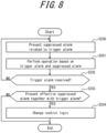
- FIG. 8 illustrates the processing from step S103 of FIG. 2 onwards.
- step S200 the processor 11 presents the consequent suppressed alarms to the operator, as in the first processing example.
- step S201 the operator performs an operation to recover from an abnormality based on the trigger alarm and the suppressed alarms, as in the first processing example.
- step S202 the processor 11 then judges whether the trigger alarm has been resolved by the recovery operation by the operator, as in the first processing example.
- the processing proceeds to step S203.
- the trigger alarm has not been resolved (step S202: NO)
- the processing returns to step S200.
- step S203 the processor 11 judges in this step whether to present suppressed alarms effective for resolving the trigger alarm subsequently to the operator.
- step S203: YES the processing proceeds to step S204.
- step S203: NO the present processing ends.
- a suppressed alarm is presented to the operator as necessary based on an operation by the operator.
- a suppressed alarm useful for resolving the trigger alarm is presented to the operator along with the trigger alarm without the operator performing an operation.
- the auxiliary information that the operator views can therefore be further optimized, which can further increase the efficiency of operations by the operator to recover from an abnormality.
- the operator may, as necessary, perform an operation to recover from an abnormality based only on the trigger alarm between the processing of step S101 and the processing of step S102 in FIG. 2 in the above-described first processing example.
- the processor 11 may then perform the processing from step S102 onward when the abnormality is not resolved by this recovery operation.
- a suppressed alarm effective for resolving the trigger alarm may be presented to the operator with greater emphasis than the other suppressed alarms.
- a suppressed alarm effective for resolving the trigger alarm may be displayed with greater emphasis than the other suppressed alarms in FIG. 6 by way of a mark, text that is colored or in bold, or the like.
- a suppressed alarm effective for resolving the trigger alarm when a suppressed alarm effective for resolving the trigger alarm is displayed to the operator with greater emphasis than the other suppressed alarms in the first processing example, and the trigger alarm is resolved with a recovery operation by the operator based on the suppressed alarm, then the suppressed alarm may be presented to the operator together with the trigger alarm without the operator performing an operation, as in the second processing example.
- a suppressed alarm effective for resolving the trigger alarm (such as "CPX002.LO”) may be displayed with emphasis in the first processing example to enable the operator to notice the suppressed alarm "CPX002.LO" when opening the window of FIG. 6 and perform an operation to recover from the abnormality in light of the suppressed alarm ("CPX002.LO").
- the suppressed alarm (“CPX002.LO”) may be displayed together with the trigger alarm ("PPX001.LL”) without the operator performing an operation, as in the second processing example.
- the operator sets the alarm classification condition.
- This condition may, however, be set using any type of machine learning, such as a neural network.
- the alarm management apparatus of the present disclosure may further include a learning unit. Based on the operation history of the operator, the learning unit optimizes the alarm classification condition so that the number of operations necessary for recovery from an abnormality decreases, for example. Subsequently, the learning unit transmits the optimized classification condition to the processor. The processor then updates the classification condition originally described in the definition file to the optimized classification condition. Alternatively, the processor may ask the operator whether to use the classification condition originally described in the definition file or the optimized classification condition. The processor judges whether to use the optimized classification condition based on the response from the operator.
- the learning unit can be implemented using one or more processors.
- An alarm management system A may be configured to include the alarm management apparatus 1, the operation monitoring terminal 2, and the engineering terminal 5 according to the above embodiment.
- the present disclosure can provide an alarm management apparatus, an alarm management system, and an alarm management method that can increase the efficiency of operations by the operator to recover from an abnormality.
Landscapes
- Engineering & Computer Science (AREA)
- Physics & Mathematics (AREA)
- General Physics & Mathematics (AREA)
- Automation & Control Theory (AREA)
- Human Computer Interaction (AREA)
- Business, Economics & Management (AREA)
- Emergency Management (AREA)
- General Engineering & Computer Science (AREA)
- Manufacturing & Machinery (AREA)
- Quality & Reliability (AREA)
- Testing And Monitoring For Control Systems (AREA)
Description
- The present disclosure relates to an alarm management apparatus, an alarm management system, and an alarm management method.
- When a piece of equipment is in an abnormal state due to process modulation or device failure in a plant or the like where a distributed control system (DCS) is used, this abnormality may trigger a secondary process abnormality in another piece of equipment. The occurrence of a process abnormality upstream, for example, may cause a process abnormality to occur downstream as well. If all of the alarms indicating abnormalities are displayed on the monitoring screen of an operator in this case, the monitoring screen becomes covered in alarms (alarm flood), confusing the operator. One approach to address this issue could be to present the operator with only the alarm indicating the original cause of the abnormality (trigger alarm), without presenting the alarms indicating secondary process abnormalities.
- Patent literature (PTL) 1 proposes designating only the trigger alarm that indicates the original cause of the abnormality as the monitoring target of the operator and removing other alarms from the monitoring target of the operator. This prevents the operator from overlooking important alarms.
WO 2014/129983 A1 relates to systems, methods, devices, computer-readable medium, and logic for managing a plurality of alarms initiated by a plurality of alarm sensors in an alarm-based environment.US 7,876,211 B2 discloses s method, apparatus and system that receive an alarm record and compare the alarm record to a suppression description that describes an alarm to be suppressed. FromUS 8,166,352 B2 , an alarm correlation method with rules and model is disclosed for suppression of alarms which will clear when another alarm clears is known. - PTL 1:
JP2010-33118A - When the monitoring target of the operator is only the trigger alarm as in
PTL 1, the operator performs an operation to recover from the abnormality based only on the trigger alarm. A recovery operation based only on the trigger alarm, however, might not resolve the abnormality. In other words, the information presented to the operator has room for improvement to increase the efficiency of operations by the operator to recover from an abnormality. - The present disclosure therefore aims to provide an alarm management apparatus, an alarm management system, and an alarm management method that can increase the efficiency of operations by the operator to recover from an abnormality.
- An alarm management apparatus according to an embodiment presents a trigger alarm, which should be presented to an operator, to the operator when the trigger alarm is included in an alarm that is received or generated, stores a suppressed alarm related to the trigger alarm, without presenting the suppressed alarm to the operator, when the suppressed alarm is included in the alarm, and presents the stored suppressed alarm to the operator based on an operation by the operator.
- In this way, the suppressed alarm is presented to the operator based on an operation by the operator, thereby increasing the efficiency of operations by the operator to recover from an abnormality.
- In an embodiment, when the suppressed alarm is effective for resolving the trigger alarm, the suppressed alarm may be presented to the operator together with the trigger alarm without the operator performing an operation.
- In this way, a suppressed alarm useful for resolving the trigger alarm is presented to the operator together with the trigger alarm without the need for a call operation by the operator, thereby further increasing the efficiency of operations by the operator to recover from an abnormality.
- In an embodiment, when the suppressed alarm is effective for resolving the trigger alarm, the suppressed alarm may be presented to the operator with greater emphasis than other suppressed alarms.
- In this way, a suppressed alarm useful for resolving the trigger alarm is displayed with greater emphasis than other suppressed alarms, thereby further increasing the efficiency of operations by the operator to recover from an abnormality.
- In an embodiment, the suppressed alarm effective for resolving the trigger alarm may be determined based on an operation history of the operator or a response from the operator.
- In an embodiment, a learning unit configured to optimize a classification condition for classifying the alarm as the trigger alarm or the suppressed alarm based on an operation history of the operator may be further included.
- Inclusion of the learning unit can further increase the efficiency of operations by the operator to recover from an abnormality.
- An alarm management system according to an embodiment includes the alarm management apparatus, an operation monitoring terminal, and an engineering terminal.
- In this way, the suppressed alarm is presented to the operator based on an operation by the operator, thereby increasing the efficiency of operations by the operator to recover from an abnormality.
- An alarm management method according to an embodiment includes presenting a trigger alarm to an operator when the trigger alarm is included in an alarm that is received or generated, storing a suppressed alarm related to the trigger alarm, without presenting the suppressed alarm to the operator, when the suppressed alarm is included in the alarm, and presenting the stored suppressed alarm to the operator based on an operation by the operator.
- In this way, the suppressed alarm is presented to the operator based on an operation by the operator, thereby increasing the efficiency of operations by the operator to recover from an abnormality.
- The present disclosure can provide an alarm management apparatus, an alarm management system, and an alarm management method that can increase the efficiency of operations by the operator to recover from an abnormality.
- In the accompanying drawings:
-
FIG. 1 illustrates the configuration of an alarm management apparatus according to an embodiment of the present disclosure; -
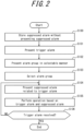
FIG. 2 is a flowchart illustrating a first processing example in the alarm management apparatus ofFIG. 1 ; -
FIG. 3 illustrates a presentation example before step S100 ofFIG. 2 ; -
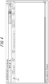
FIG. 4 illustrates a presentation example of step S101 ofFIG. 2 ; -
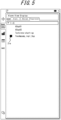
FIG. 5 illustrates a presentation example of step S101 ofFIG. 2 ; -
FIG. 6 illustrates a presentation example of step S104 ofFIG. 2 ; -
FIG. 7 illustrates a presentation example of step S106 ofFIG. 2 ; -
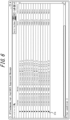
FIG. 8 is a flowchart illustrating a second processing example in the alarm management apparatus ofFIG. 1 ; -
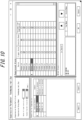
FIG. 9 illustrates an example of a definition file before the processing of step S204 ofFIG. 8 ; and -
FIG. 10 illustrates an example of the definition file after the processing of step S204 ofFIG. 8 . - Embodiments of the present disclosure are described below with reference to the drawings. Identical reference signs in the drawings indicate identical or equivalent constituent elements.
- As illustrated in
FIG. 1 , analarm management apparatus 1 according to an embodiment of the present disclosure can perform data communication with anoperation monitoring terminal 2, acontroller 3, and an engineering terminal 5. - The
operation monitoring terminal 2 may be any terminal capable of including adisplay 21 that displays the result of processing by thealarm management apparatus 1 and aninput interface 22 capable of receiving operations by the operator. Examples of theoperation monitoring terminal 2 include a desktop PC, a smartphone, and a tablet terminal. - The
controller 3 is connected to field devices and the like and controls these devices. Thecontroller 3 detects an abnormality from process modulation or a field device and transmits information based on the abnormality to thealarm management apparatus 1 via a control network 4. When thecontroller 3 has a function to generate an alarm based on the above-described abnormality, thecontroller 3 may transmit the alarm generated by thecontroller 3 to thealarm management apparatus 1 via the control network 4. Only onecontroller 3 is illustrated inFIG. 1 , but more than one controller may be provided. - The engineering terminal 5 can include an
input interface 51 capable of receiving an operation by an engineer. The engineer can use theinput interface 51 to create a definition file, described below. The definition file created by the engineer is downloaded onto thealarm management apparatus 1 via the control network 4 and is used in the processing executed by thealarm management apparatus 1. Examples of the engineering terminal 5 include a desktop PC, a smartphone, and a tablet. The "definition file" is described below. - When a piece of equipment is in an abnormal state in a plant or the like due to process modulation or device failure, this abnormality may trigger a secondary process abnormality in another piece of equipment. The occurrence of a process abnormality upstream, for example, may cause a process abnormality to occur downstream as well. If all of the alarms indicating abnormalities are displayed on the monitoring screen of an operator in this case, the monitoring screen becomes covered in alarms (alarm flood), confusing the operator. One approach to address this issue has been to present the operator with only the alarm indicating the original cause of the abnormality (trigger alarm), without presenting the alarms indicating secondary process abnormalities. The operator can efficiently perform operations to recover from the process abnormality that caused the trigger alarm, however, when an alarm indicating a secondary process abnormality due to the process abnormality that caused the trigger alarm (i.e. a suppressed alarm not presented to the operator with a known technique) is also presented to the operator as necessary. In other words, associating the trigger alarm with a suppressed alarm enables the operator to perform operations efficiently to recover from the process abnormality that caused the trigger alarm. As an example of this association between then trigger alarm and the suppressed alarm, an engineer can use the engineering terminal 5 to create a definition file for associating the trigger alarm and the suppressed alarm. The definition file contains a description of a trigger alarm, a suppressed alarm that occurs consequently with the process abnormality that caused the trigger alarm, and an alarm group to which the trigger alarm and the suppressed alarm belong.
- The
alarm management apparatus 1 may include aprocessor 11, astorage 12, and acommunication interface 15. The components of thealarm management apparatus 1 are described below in detail. - The
storage 12 may include afirst storage area 13 and asecond storage area 14. Thestorage 12 can be implemented using a semiconductor memory, a magnetic memory, or an optical memory, for example. Examples of thestorage 12 include read only memory (ROM), flash memory, and dynamic random access memory (DRAM), which is capable of temporarily storing data. The number ofstorages 12 is not limited to one, and thefirst storage area 13 and thesecond storage area 14 may be located in different storages. Thestorage 12 may be an external storage apparatus that is attached to thealarm management apparatus 1. - When an abnormality occurs in a plant or the like, the
processor 11 receives information based on the abnormality and generates an alarm. For example, theprocessor 11 can receive the information from thecontroller 3 via the control network 4 and thecommunication interface 15. Theprocessor 11 can be implemented using one or a plurality of processors. - The
processor 11 judges whether a trigger alarm is included in the generated alarm. To make this judgment, theprocessor 11 can refer to the above-described definition file. - When a trigger alarm is included, the
processor 11 presents the trigger alarm to the operator. For example, theprocessor 11 can display the trigger alarm on thedisplay 21 of theoperation monitoring terminal 2.FIG. 4 illustrates a window displayed on thedisplay 21 of theoperation monitoring terminal 2 when the trigger alarm is "PPX001.LL". The label "PPX001.LL" indicates that the state of an alarm occurring on the device with the tag name "PPX001" is LL (lower lower limit alarm). Theprocessor 11 also presents the alarm group to which the trigger alarm belongs in a manner selectable by the operator. For example, theprocessor 11 can display the alarm group to which the trigger alarm belongs on thedisplay 21 of the operation monitoring terminal 2 in a selectable manner.FIG. 5 illustrates a list of alarm groups in a window displayed on thedisplay 21 of theoperation monitoring terminal 2. While details are provided below, the operator can refer to the "Suppression Group" column displayed in the window ofFIG. 4 to confirm the trigger alarm and the alarm group to which the trigger alarm belongs. The window ofFIG. 6 is displayed when the operator clicks or the like to select theicon 21a displayed in the window ofFIG. 5 . Examples of theicon 21a include symbols, characters, numbers, graphics, or a combination thereof. The operator may, however, select the alarm group described above in the window ofFIG. 4 without going through the window ofFIG. 5 . - The
processor 11 can enter a standby state when a trigger alarm is not included in the generated alarm. - Furthermore, the
processor 11 judges whether a suppressed alarm related to the above-described trigger alarm is included in the generated alarm. To make this judgment, theprocessor 11 can refer to the above-described definition file. - When a suppressed alarm related to the trigger alarm is included, the
processor 11 stores the suppressed alarm in thestorage 12, for example, without presenting the suppressed alarm to the operator. Based on an operation by the operator, theprocessor 11 presents the suppressed alarms stored in thestorage 12, for example, to the operator. In greater detail, theprocessor 11 associates the suppressed alarm with a predetermined alarm group based on the above-described definition file and stores the result in thesecond storage area 14, for example. The operator then refers to the window ofFIG. 4 and the window ofFIG. 5 to confirm a predetermined alarm group to which the trigger alarm belongs and selects theicon 21a displayed in the window ofFIG. 5 by clicking or the like. Consequently, theprocessor 11 receives notification, via thecommunication interface 15, that the predetermined alarm group has been selected by the operator. The processor then refers to thesecond storage area 14, for example, and presents the operator with the suppressed alarms belonging to the predetermined alarm group selected by the operator. Consequently, the window ofFIG. 6 , for example, is displayed on thedisplay 21 of theoperation monitoring terminal 2.FIG. 6 is a window indicating that the suppressed alarms belonging to the same alarm group (group name "feedwpump_repl_Sup") as the trigger alarm "PPX001.LL" are "TIC001.LL", "TIC001.LO", "PIC002.LL", "PIC002.LO", "PIC001.LL", "PIC001.LO", "TIC006.LL", "TIC006.LO", "CPX002.LL", "CPX002.LO", "CPX001.LL", "CPX001.LO", and "PPX001.LO". Here, LO represents the state in which a lower limit alarm has occurred. - The
processor 11 can enter the standby state when a suppressed alarm 25 related to the trigger alarm is not included. - When the process value of a device exceeds a predetermined threshold, the
processor 11 may judge that an alarm is to be presented to the operator. The operator can use the definition file to freely set the "predetermined threshold" for each trigger alarm and suppressed alarm. - The
communication interface 15 may include one or a plurality of communication interfaces capable of communicating with each of theoperation monitoring terminal 2, thecontroller 3, and the engineering terminal 5. The communication interface may be any communication interface capable of data communication in a wired or wireless manner. - Next, a first processing example which is not part of the present invention that can be executed by the
alarm management apparatus 1 according to the present embodiment is described with reference toFIG. 2 . - Normally, the logic of the
processor 11 is set so that operator is notified only of trigger alarms, whereas notification of suppressed alarms is suppressed automatically. This state is referred to below as the "alarm suppressed state". The alarm suppressed state is, for example, set as necessary by the operator operating a selection screen on thedisplay 21 via theinput interface 22 of theoperation monitoring terminal 2. For example, via the window ofFIG. 3 displayed on thedisplay 21 of theoperation monitoring terminal 2, the operator can set the suppressed alarms belonging to an alarm group (group name "feedwpump_repl_Sup") to the alarm suppressed state and can set the suppressed alarms belonging to other alarm groups (group names "ASup01", "ASup02", and "Turbinne-start-up") to an alarm non-suppressed state. The first processing example begins inFIG. 2 in this state. - In step S100, the
processor 11 stores suppressed alarms belonging to alarm groups in the alarm suppressed state in the storage, without presenting these suppressed alarms to the operator. - Subsequently, in step S101, the
processor 11 presents the trigger alarm to the operator. Here, the window ofFIG. 5 was already being displayed on thedisplay 21 of theoperation monitoring terminal 2, and the window ofFIG. 4 is additionally displayed separately from the window ofFIG. 5 in step S101. - Subsequently, in step S102, the
processor 11 presents the operator with the alarm group to which the trigger alarm presented to the operator in step S101 belongs. The alarm group is presented in a selectable manner. - Subsequently, in step S103, the operator selects the alarm group presented in a selectable manner in step S102. The operator can refer to the "Suppression Group" column displayed in the window of
FIG. 4 , confirm the predetermined alarm group to which the trigger alarm in step S101 belongs (here, the group name "feedwpump_repl_Sup"), and select theicon 21a in the window ofFIG. 5 by clicking or the like to select the predetermined alarm group (here, the group name "feedwpump_repl_Sup"). When the alarm group is also displayed in the window ofFIG. 4 , the operator may select the alarm group (group name "feedwpump_repl_Sup") without passing through the window ofFIG. 5 . - Subsequently, in step S104, the
processor 11 refers to thestorage 12 and presents the suppressed alarms belonging to the alarm group selected in step S103 to the operator. In step S104, the window ofFIG. 6 is additionally displayed on thedisplay 21 of theoperation monitoring terminal 2 separately from the window ofFIG. 4 and the window ofFIG. 5 . In the window ofFIG. 6 , anicon 21b indicating an abnormality is displayed for each suppressed alarm. Examples of theicon 21b include symbols, characters, numbers, graphics, or a combination thereof. - Subsequently, in step S105, the operator performs an operation to recover from the abnormality based on the trigger alarm presented in step S101 and the suppressed alarms presented in step S104.
- Here, when the abnormality is resolved by the recovery operation by the operator, the
processor 11 can present a corresponding notification to the operator. For example, when the abnormality of the suppressed alarm "CPX002.LO" is resolved, theicon 21b displayed in the window ofFIG. 6 to indicate the abnormality changes to an icon indicating a normal state. Theicon 21c displayed in the window ofFIG. 4 to indicate the abnormality changes to theicon 21d displayed in the window ofFIG. 7 to indicate a normal state when the trigger alarm "PPX001.LL" related to the suppressed alarm "CPX002.LO" is also resolved. In other words, the window displayed on thedisplay 21 of the operation monitoring terminal 2 changes from the "window ofFIG. 4 , window ofFIG. 5 , window ofFIG. 6 " to the "window ofFIG. 7 , window ofFIG. 5 , window ofFIG. 6 (in which theicon 21b indicating an abnormality has changed to an icon indicating a normal state). The windows ofFIGS. 6 ,7 disappear from thedisplay 21 of the operation monitoring terminal 2 in response to the operator performing an operation via theinput interface 22 of theoperation monitoring terminal 2. When a plurality of trigger alarms occur, however, the resolution of one trigger alarm does not necessarily resolve the other trigger alarms. The operator may therefore not always close the window ofFIG. 7 . Examples of theicons - Subsequently, in step S106, the
processor 11 judges whether the trigger alarm has been resolved by the recovery operation in step S105. When the trigger alarm has been resolved (step S106: YES), the present processing ends. When the trigger alarm has not been resolved (step S106: NO), the processing returns to step S104. - In the first processing example, the consequent suppressed alarms that are normally not presented to the operator to avoid an alarm flood are presented intentionally based on an operation by the operator. The number of alarms can therefore be reduced to prevent an important alarm from being overlooked while also enabling suppressed alarms, which are normally not presented, to be used effectively as auxiliary information for an operation to recover from an abnormality. Furthermore, the operator can confirm that recovery from the trigger alarm has also resolved all of the secondary process abnormalities that occurred. This can increase the efficiency of operations by the operator to recover from an abnormality.
- Next, a second processing example according to the invention that can be executed by the
alarm management apparatus 1 according to the present embodiment is described with reference toFIG. 8 . - The second processing example differs from the first processing example in that suppressed alarms effective for resolving the trigger alarm are presented to the operator along with the trigger alarm, without the operator performing an operation. The
processor 11 performs similar processing to steps S100 to S103 ofFIG. 2 in the second processing example as well. Among the processing included in the second processing example,FIG. 8 illustrates the processing from step S103 ofFIG. 2 onwards. - In step S200, the
processor 11 presents the consequent suppressed alarms to the operator, as in the first processing example. - Subsequently, in step S201, the operator performs an operation to recover from an abnormality based on the trigger alarm and the suppressed alarms, as in the first processing example.
- In step S202, the
processor 11 then judges whether the trigger alarm has been resolved by the recovery operation by the operator, as in the first processing example. When the trigger alarm has been resolved (step S202: YES), the processing proceeds to step S203. When the trigger alarm has not been resolved (step S202: NO), the processing returns to step S200. - In the case of proceeding to step S203, the
processor 11 judges in this step whether to present suppressed alarms effective for resolving the trigger alarm subsequently to the operator. When the suppressed alarms are to be presented to the operator with the trigger alarm (step S203: YES), the processing proceeds to step S204. When the suppressed alarms are not to be presented to the operator with the trigger alarm (step S203: NO), the present processing ends. processing example, a suppressed alarm is presented to the operator as necessary based on an operation by the operator. In the second processing example, a suppressed alarm useful for resolving the trigger alarm is presented to the operator along with the trigger alarm without the operator performing an operation. The auxiliary information that the operator views can therefore be further optimized, which can further increase the efficiency of operations by the operator to recover from an abnormality. - The present disclosure has been explained based on drawings and embodiments, but it should be noted that a person of ordinary skill in the art could easily make a variety of modifications and adjustments on the basis of the present disclosure. Therefore, such changes and modifications are to be understood as included within the scope of the present disclosure. For example, the functions and the like included in the various steps and the like may be reordered in any logically consistent way. Furthermore, steps and the like may be combined into one or divided.
- For example, the operator may, as necessary, perform an operation to recover from an abnormality based only on the trigger alarm between the processing of step S101 and the processing of step S102 in
FIG. 2 in the above-described first processing example. Theprocessor 11 may then perform the processing from step S102 onward when the abnormality is not resolved by this recovery operation. - In the above-described first processing example and second processing example, a suppressed alarm effective for resolving the trigger alarm may be presented to the operator with greater emphasis than the other suppressed alarms. For example, a suppressed alarm effective for resolving the trigger alarm may be displayed with greater emphasis than the other suppressed alarms in
FIG. 6 by way of a mark, text that is colored or in bold, or the like. Furthermore, when a suppressed alarm effective for resolving the trigger alarm is displayed to the operator with greater emphasis than the other suppressed alarms in the first processing example, and the trigger alarm is resolved with a recovery operation by the operator based on the suppressed alarm, then the suppressed alarm may be presented to the operator together with the trigger alarm without the operator performing an operation, as in the second processing example. Specifically, a suppressed alarm effective for resolving the trigger alarm (such as "CPX002.LO") may be displayed with emphasis in the first processing example to enable the operator to notice the suppressed alarm "CPX002.LO" when opening the window ofFIG. 6 and perform an operation to recover from the abnormality in light of the suppressed alarm ("CPX002.LO"). When the abnormality is resolved, the suppressed alarm ("CPX002.LO") may be displayed together with the trigger alarm ("PPX001.LL") without the operator performing an operation, as in the second processing example. - In the above embodiment, the operator sets the alarm classification condition. This condition may, however, be set using any type of machine learning, such as a neural network. The alarm management apparatus of the present disclosure may further include a learning unit. Based on the operation history of the operator, the learning unit optimizes the alarm classification condition so that the number of operations necessary for recovery from an abnormality decreases, for example. Subsequently, the learning unit transmits the optimized classification condition to the processor. The processor then updates the classification condition originally described in the definition file to the optimized classification condition. Alternatively, the processor may ask the operator whether to use the classification condition originally described in the definition file or the optimized classification condition. The processor judges whether to use the optimized classification condition based on the response from the operator. The learning unit can be implemented using one or more processors.
- An alarm management system A may be configured to include the
alarm management apparatus 1, theoperation monitoring terminal 2, and the engineering terminal 5 according to the above embodiment. - The present disclosure can provide an alarm management apparatus, an alarm management system, and an alarm management method that can increase the efficiency of operations by the operator to recover from an abnormality.
Claims (4)
- An alarm management apparatus (1) configured to present (S200) a trigger alarm indicating an original cause of abnormality to an operator when the trigger alarm is included in a plurality of alarms that are received or generated;store at least one suppressed alarm indicating a secondary process abnormality due to a process abnormality that caused the trigger alarm when the at least one suppressed alarm is included in the plurality of alarms, the alarm management apparatus being characterized in that it is further configured topresent the at least one suppressed alarm that is stored to the operator based on an operation by the operator,determine a particular suppressed alarm that is effective for resolving the trigger alarm among the stored at least one suppressed alarms based on the fact that the trigger alarm is resolved as a result of the operator previously performing an operation to recover from an anomaly based on the particular suppressed alarm, or based the operator's previous input regarding whether the particular suppressed alarm is effective for resolving the trigger alarm, andchange (S204) a control logic so that the particular suppressed alarm that is determined to be effective for resolving the trigger alarm is subsequently presented to the operator together with the trigger alarm without the operator performing an operation.
- The alarm management apparatus of claim 1, wherein the alarm management apparatus is configured to present the particular suppressed alarm to the operator with greater emphasis than other suppressed alarms.
- An alarm management system comprising:the alarm management apparatus of any one of claims 1 to 2;an operation monitoring terminal; andan engineering terminal.
- An alarm management method using an alarm management apparatus, the alarm management method comprising:presenting a trigger alarm indicating an original cause of abnormality to an operator when the trigger alarm is included in a plurality of alarms that are received or generated;storing at least one suppressed alarm indicating a secondary process abnormality due to a process abnormality that caused the trigger alarm when the at least one suppressed alarm is included in the plurality of alarms;presenting the at least one suppressed alarm that is stored to the operator based on an operation by the operator,determining a particular suppressed alarm that is effective for resolving the trigger alarm among the stored at least one suppressed alarms based on the fact that the trigger alarm is resolved as a result of the operator previously performing an operation to recover from an anomaly based on the particular suppressed alarm, or based the operator's previous input regarding whether the particular suppressed alarm is effective for resolving the trigger alarm, andchanging a control logic so that the particular suppressed alarm that is determined to be effective for resolving the trigger alarm is subsequently presented to the operator together with the trigger alarm without the operator performing an operation.
Applications Claiming Priority (1)
| Application Number | Priority Date | Filing Date | Title |
|---|---|---|---|
| JP2019146753A JP7344041B2 (en) | 2019-08-08 | 2019-08-08 | Alarm management device, alarm management system, and alarm management method |
Publications (2)
| Publication Number | Publication Date |
|---|---|
| EP3772677A1 EP3772677A1 (en) | 2021-02-10 |
| EP3772677B1 true EP3772677B1 (en) | 2024-10-02 |
Family
ID=71950543
Family Applications (1)
| Application Number | Title | Priority Date | Filing Date |
|---|---|---|---|
| EP20189658.6A Active EP3772677B1 (en) | 2019-08-08 | 2020-08-05 | Alarm management apparatus, alarm management system, and alarm management method |
Country Status (4)
| Country | Link |
|---|---|
| US (1) | US11869335B2 (en) |
| EP (1) | EP3772677B1 (en) |
| JP (1) | JP7344041B2 (en) |
| CN (1) | CN112346433B (en) |
Family Cites Families (17)
| Publication number | Priority date | Publication date | Assignee | Title |
|---|---|---|---|---|
| JPH05108412A (en) * | 1991-10-15 | 1993-04-30 | Toshiba Corp | Plant alarm |
| JP3545513B2 (en) * | 1995-09-28 | 2004-07-21 | 株式会社東芝 | Warning device for plant status |
| US6774786B1 (en) * | 2000-11-07 | 2004-08-10 | Fisher-Rosemount Systems, Inc. | Integrated alarm display in a process control network |
| JP2001195124A (en) * | 2000-01-07 | 2001-07-19 | Toshiba Corp | Plant monitoring and control equipment |
| JP2004086338A (en) * | 2002-08-23 | 2004-03-18 | Toshiba Corp | Alarm control processor |
| JP4247743B2 (en) | 2004-06-29 | 2009-04-02 | 横河電機株式会社 | Alarm monitoring device |
| JP5024083B2 (en) * | 2008-01-31 | 2012-09-12 | 横河電機株式会社 | Alarm management device |
| US7876211B2 (en) * | 2008-02-21 | 2011-01-25 | Honeywell International Inc. | Apparatus and method for alarm suppression in a monitoring system |
| JP2010033118A (en) * | 2008-07-25 | 2010-02-12 | Yokogawa Electric Corp | Alarm management device |
| US8166352B2 (en) * | 2009-06-30 | 2012-04-24 | Alcatel Lucent | Alarm correlation system |
| WO2014129983A1 (en) * | 2013-02-21 | 2014-08-28 | Thai Oil Public Company Limited | Methods, systems, and devices for managing a plurality of alarms |
| US9360816B1 (en) * | 2014-12-15 | 2016-06-07 | Ricoh Company, Ltd. | Toner bottle driving device control method and image forming apparatus |
| JP6649756B2 (en) * | 2015-11-26 | 2020-02-19 | アズビル株式会社 | Display device and method |
| US9754478B1 (en) * | 2016-05-31 | 2017-09-05 | Honeywell International Inc. | Reducing nuisance notifications from a building automation system |
| JP2018120456A (en) * | 2017-01-26 | 2018-08-02 | 三菱日立パワーシステムズ株式会社 | Alarm display system and alarm display method |
| US10388140B2 (en) * | 2017-10-18 | 2019-08-20 | Bently Nevada, Llc | Automated alarm shelving |
| CN109474473A (en) * | 2018-12-06 | 2019-03-15 | 浙江航天恒嘉数据科技有限公司 | A kind of general alarm system and method towards perception data monitoring and warning |
-
2019
- 2019-08-08 JP JP2019146753A patent/JP7344041B2/en active Active
-
2020
- 2020-08-05 CN CN202010775864.6A patent/CN112346433B/en active Active
- 2020-08-05 EP EP20189658.6A patent/EP3772677B1/en active Active
- 2020-08-06 US US16/986,521 patent/US11869335B2/en active Active
Also Published As
| Publication number | Publication date |
|---|---|
| JP7344041B2 (en) | 2023-09-13 |
| US20210043062A1 (en) | 2021-02-11 |
| CN112346433B (en) | 2024-08-27 |
| CN112346433A (en) | 2021-02-09 |
| EP3772677A1 (en) | 2021-02-10 |
| US11869335B2 (en) | 2024-01-09 |
| JP2021026716A (en) | 2021-02-22 |
Similar Documents
| Publication | Publication Date | Title |
|---|---|---|
| JP5816166B2 (en) | Failure processing method and processing apparatus | |
| CN105487458A (en) | Methods and apparatus to filter process control system alarms based on alarm source type and/or alarm purpose | |
| US20070297557A1 (en) | Plant information processing system and plant information processing method | |
| US10698398B2 (en) | Alarm display system and alarm display method | |
| CN110752944B (en) | Alarm order dispatching method and device | |
| US5617311A (en) | Information system for operating complex plant | |
| US12056033B2 (en) | Anomaly location estimating apparatus, method, and program | |
| CN101876828A (en) | A method of managing aircraft alerts and a device implementing said method | |
| JP5772128B2 (en) | Method and apparatus for providing industrial plant information | |
| US9336075B2 (en) | Monitoring apparatus, monitoring method, and storage medium | |
| US20220334914A1 (en) | Anomaly coping support apparatus, method, and program | |
| EP3772677B1 (en) | Alarm management apparatus, alarm management system, and alarm management method | |
| US20180308027A1 (en) | Apparatus and method for determining and rendering risk assessments to users | |
| JP4867908B2 (en) | Monitoring system, network monitoring apparatus, and service execution environment monitoring method | |
| CN105074833B (en) | Device for detecting unauthorized manipulation of the system state of a control and regulation unit and nuclear installation having the device | |
| JP5314741B2 (en) | Remote monitoring system | |
| US20200073777A1 (en) | Method for Automatically Evaluating Alarm Clusters | |
| EP3889702A1 (en) | Controller system | |
| KR101447031B1 (en) | System for searching emergency operating procedure in nuclear power plant and method thereof | |
| US20230385406A1 (en) | Response support device and response support method | |
| CN117636497A (en) | A power grid dispatching machine room inspection control method, system, terminal and medium | |
| EP3772676B1 (en) | Alarm management system and alarm management method | |
| EP3748451A1 (en) | Information processing apparatus, alarm management system, and alarm management method | |
| US10848400B2 (en) | Network entity for monitoring a plurality of processes of a communication system | |
| JP2005100027A (en) | The failure information display device of the programmable controller has a content that is divided into detailed information about the relevant failure according to user-defined attributes in the failure details display section, each time this attribute is selected. A fault information display device for a programmable controller, which is displayed on the screen. |
Legal Events
| Date | Code | Title | Description |
|---|---|---|---|
| PUAI | Public reference made under article 153(3) epc to a published international application that has entered the european phase |
Free format text: ORIGINAL CODE: 0009012 |
|
| STAA | Information on the status of an ep patent application or granted ep patent |
Free format text: STATUS: THE APPLICATION HAS BEEN PUBLISHED |
|
| AK | Designated contracting states |
Kind code of ref document: A1 Designated state(s): AL AT BE BG CH CY CZ DE DK EE ES FI FR GB GR HR HU IE IS IT LI LT LU LV MC MK MT NL NO PL PT RO RS SE SI SK SM TR |
|
| AX | Request for extension of the european patent |
Extension state: BA ME |
|
| STAA | Information on the status of an ep patent application or granted ep patent |
Free format text: STATUS: REQUEST FOR EXAMINATION WAS MADE |
|
| STAA | Information on the status of an ep patent application or granted ep patent |
Free format text: STATUS: EXAMINATION IS IN PROGRESS |
|
| 17P | Request for examination filed |
Effective date: 20210806 |
|
| RBV | Designated contracting states (corrected) |
Designated state(s): AL AT BE BG CH CY CZ DE DK EE ES FI FR GB GR HR HU IE IS IT LI LT LU LV MC MK MT NL NO PL PT RO RS SE SI SK SM TR |
|
| 17Q | First examination report despatched |
Effective date: 20210902 |
|
| P01 | Opt-out of the competence of the unified patent court (upc) registered |
Effective date: 20230603 |
|
| GRAP | Despatch of communication of intention to grant a patent |
Free format text: ORIGINAL CODE: EPIDOSNIGR1 |
|
| STAA | Information on the status of an ep patent application or granted ep patent |
Free format text: STATUS: GRANT OF PATENT IS INTENDED |
|
| INTG | Intention to grant announced |
Effective date: 20240404 |
|
| GRAS | Grant fee paid |
Free format text: ORIGINAL CODE: EPIDOSNIGR3 |
|
| GRAA | (expected) grant |
Free format text: ORIGINAL CODE: 0009210 |
|
| STAA | Information on the status of an ep patent application or granted ep patent |
Free format text: STATUS: THE PATENT HAS BEEN GRANTED |
|
| AK | Designated contracting states |
Kind code of ref document: B1 Designated state(s): AL AT BE BG CH CY CZ DE DK EE ES FI FR GB GR HR HU IE IS IT LI LT LU LV MC MK MT NL NO PL PT RO RS SE SI SK SM TR |
|
| REG | Reference to a national code |
Ref country code: GB Ref legal event code: FG4D |
|
| REG | Reference to a national code |
Ref country code: CH Ref legal event code: EP |
|
| REG | Reference to a national code |
Ref country code: DE Ref legal event code: R096 Ref document number: 602020038599 Country of ref document: DE |
|
| REG | Reference to a national code |
Ref country code: IE Ref legal event code: FG4D |
|
| REG | Reference to a national code |
Ref country code: LT Ref legal event code: MG9D |
|
| REG | Reference to a national code |
Ref country code: NL Ref legal event code: MP Effective date: 20241002 |
|
| REG | Reference to a national code |
Ref country code: AT Ref legal event code: MK05 Ref document number: 1728930 Country of ref document: AT Kind code of ref document: T Effective date: 20241002 |
|
| PG25 | Lapsed in a contracting state [announced via postgrant information from national office to epo] |
Ref country code: NL Free format text: LAPSE BECAUSE OF FAILURE TO SUBMIT A TRANSLATION OF THE DESCRIPTION OR TO PAY THE FEE WITHIN THE PRESCRIBED TIME-LIMIT Effective date: 20241002 |
|
| PG25 | Lapsed in a contracting state [announced via postgrant information from national office to epo] |
Ref country code: NL Free format text: LAPSE BECAUSE OF FAILURE TO SUBMIT A TRANSLATION OF THE DESCRIPTION OR TO PAY THE FEE WITHIN THE PRESCRIBED TIME-LIMIT Effective date: 20241002 |
|
| PG25 | Lapsed in a contracting state [announced via postgrant information from national office to epo] |
Ref country code: HR Free format text: LAPSE BECAUSE OF FAILURE TO SUBMIT A TRANSLATION OF THE DESCRIPTION OR TO PAY THE FEE WITHIN THE PRESCRIBED TIME-LIMIT Effective date: 20241002 Ref country code: IS Free format text: LAPSE BECAUSE OF FAILURE TO SUBMIT A TRANSLATION OF THE DESCRIPTION OR TO PAY THE FEE WITHIN THE PRESCRIBED TIME-LIMIT Effective date: 20250202 Ref country code: PT Free format text: LAPSE BECAUSE OF FAILURE TO SUBMIT A TRANSLATION OF THE DESCRIPTION OR TO PAY THE FEE WITHIN THE PRESCRIBED TIME-LIMIT Effective date: 20250203 |
|
| PG25 | Lapsed in a contracting state [announced via postgrant information from national office to epo] |
Ref country code: FI Free format text: LAPSE BECAUSE OF FAILURE TO SUBMIT A TRANSLATION OF THE DESCRIPTION OR TO PAY THE FEE WITHIN THE PRESCRIBED TIME-LIMIT Effective date: 20241002 |
|
| PG25 | Lapsed in a contracting state [announced via postgrant information from national office to epo] |
Ref country code: BG Free format text: LAPSE BECAUSE OF FAILURE TO SUBMIT A TRANSLATION OF THE DESCRIPTION OR TO PAY THE FEE WITHIN THE PRESCRIBED TIME-LIMIT Effective date: 20241002 |
|
| PG25 | Lapsed in a contracting state [announced via postgrant information from national office to epo] |
Ref country code: ES Free format text: LAPSE BECAUSE OF FAILURE TO SUBMIT A TRANSLATION OF THE DESCRIPTION OR TO PAY THE FEE WITHIN THE PRESCRIBED TIME-LIMIT Effective date: 20241002 |
|
| PG25 | Lapsed in a contracting state [announced via postgrant information from national office to epo] |
Ref country code: NO Free format text: LAPSE BECAUSE OF FAILURE TO SUBMIT A TRANSLATION OF THE DESCRIPTION OR TO PAY THE FEE WITHIN THE PRESCRIBED TIME-LIMIT Effective date: 20250102 |
|
| PG25 | Lapsed in a contracting state [announced via postgrant information from national office to epo] |
Ref country code: LV Free format text: LAPSE BECAUSE OF FAILURE TO SUBMIT A TRANSLATION OF THE DESCRIPTION OR TO PAY THE FEE WITHIN THE PRESCRIBED TIME-LIMIT Effective date: 20241002 Ref country code: AT Free format text: LAPSE BECAUSE OF FAILURE TO SUBMIT A TRANSLATION OF THE DESCRIPTION OR TO PAY THE FEE WITHIN THE PRESCRIBED TIME-LIMIT Effective date: 20241002 Ref country code: GR Free format text: LAPSE BECAUSE OF FAILURE TO SUBMIT A TRANSLATION OF THE DESCRIPTION OR TO PAY THE FEE WITHIN THE PRESCRIBED TIME-LIMIT Effective date: 20250103 |
|
| PG25 | Lapsed in a contracting state [announced via postgrant information from national office to epo] |
Ref country code: CZ Free format text: LAPSE BECAUSE OF FAILURE TO SUBMIT A TRANSLATION OF THE DESCRIPTION OR TO PAY THE FEE WITHIN THE PRESCRIBED TIME-LIMIT Effective date: 20241002 Ref country code: PL Free format text: LAPSE BECAUSE OF FAILURE TO SUBMIT A TRANSLATION OF THE DESCRIPTION OR TO PAY THE FEE WITHIN THE PRESCRIBED TIME-LIMIT Effective date: 20241002 |
|
| PG25 | Lapsed in a contracting state [announced via postgrant information from national office to epo] |
Ref country code: RS Free format text: LAPSE BECAUSE OF FAILURE TO SUBMIT A TRANSLATION OF THE DESCRIPTION OR TO PAY THE FEE WITHIN THE PRESCRIBED TIME-LIMIT Effective date: 20250102 |
|
| PG25 | Lapsed in a contracting state [announced via postgrant information from national office to epo] |
Ref country code: SM Free format text: LAPSE BECAUSE OF FAILURE TO SUBMIT A TRANSLATION OF THE DESCRIPTION OR TO PAY THE FEE WITHIN THE PRESCRIBED TIME-LIMIT Effective date: 20241002 |
|
| REG | Reference to a national code |
Ref country code: DE Ref legal event code: R097 Ref document number: 602020038599 Country of ref document: DE |
|
| PG25 | Lapsed in a contracting state [announced via postgrant information from national office to epo] |
Ref country code: DK Free format text: LAPSE BECAUSE OF FAILURE TO SUBMIT A TRANSLATION OF THE DESCRIPTION OR TO PAY THE FEE WITHIN THE PRESCRIBED TIME-LIMIT Effective date: 20241002 |
|
| PG25 | Lapsed in a contracting state [announced via postgrant information from national office to epo] |
Ref country code: EE Free format text: LAPSE BECAUSE OF FAILURE TO SUBMIT A TRANSLATION OF THE DESCRIPTION OR TO PAY THE FEE WITHIN THE PRESCRIBED TIME-LIMIT Effective date: 20241002 |
|
| PG25 | Lapsed in a contracting state [announced via postgrant information from national office to epo] |
Ref country code: RO Free format text: LAPSE BECAUSE OF FAILURE TO SUBMIT A TRANSLATION OF THE DESCRIPTION OR TO PAY THE FEE WITHIN THE PRESCRIBED TIME-LIMIT Effective date: 20241002 |
|
| PG25 | Lapsed in a contracting state [announced via postgrant information from national office to epo] |
Ref country code: SK Free format text: LAPSE BECAUSE OF FAILURE TO SUBMIT A TRANSLATION OF THE DESCRIPTION OR TO PAY THE FEE WITHIN THE PRESCRIBED TIME-LIMIT Effective date: 20241002 |
|
| PG25 | Lapsed in a contracting state [announced via postgrant information from national office to epo] |
Ref country code: IT Free format text: LAPSE BECAUSE OF FAILURE TO SUBMIT A TRANSLATION OF THE DESCRIPTION OR TO PAY THE FEE WITHIN THE PRESCRIBED TIME-LIMIT Effective date: 20241002 |
|
| PLBE | No opposition filed within time limit |
Free format text: ORIGINAL CODE: 0009261 |
|
| STAA | Information on the status of an ep patent application or granted ep patent |
Free format text: STATUS: NO OPPOSITION FILED WITHIN TIME LIMIT |
|
| PG25 | Lapsed in a contracting state [announced via postgrant information from national office to epo] |
Ref country code: SE Free format text: LAPSE BECAUSE OF FAILURE TO SUBMIT A TRANSLATION OF THE DESCRIPTION OR TO PAY THE FEE WITHIN THE PRESCRIBED TIME-LIMIT Effective date: 20241002 |
|
| 26N | No opposition filed |
Effective date: 20250703 |
|
| PGFP | Annual fee paid to national office [announced via postgrant information from national office to epo] |
Ref country code: DE Payment date: 20250828 Year of fee payment: 6 |
|
| REG | Reference to a national code |
Ref country code: CH Ref legal event code: H13 Free format text: ST27 STATUS EVENT CODE: U-0-0-H10-H13 (AS PROVIDED BY THE NATIONAL OFFICE) Effective date: 20260324 |
|
| PG25 | Lapsed in a contracting state [announced via postgrant information from national office to epo] |
Ref country code: MC Free format text: LAPSE BECAUSE OF FAILURE TO SUBMIT A TRANSLATION OF THE DESCRIPTION OR TO PAY THE FEE WITHIN THE PRESCRIBED TIME-LIMIT Effective date: 20241002 |
|
| PG25 | Lapsed in a contracting state [announced via postgrant information from national office to epo] |
Ref country code: LU Free format text: LAPSE BECAUSE OF NON-PAYMENT OF DUE FEES Effective date: 20250805 |
|
| PG25 | Lapsed in a contracting state [announced via postgrant information from national office to epo] |
Ref country code: CH Free format text: LAPSE BECAUSE OF NON-PAYMENT OF DUE FEES Effective date: 20250831 |