EP3772653A1 - Voltage sensing structure - Google Patents
Voltage sensing structure Download PDFInfo
- Publication number
- EP3772653A1 EP3772653A1 EP20189839.2A EP20189839A EP3772653A1 EP 3772653 A1 EP3772653 A1 EP 3772653A1 EP 20189839 A EP20189839 A EP 20189839A EP 3772653 A1 EP3772653 A1 EP 3772653A1
- Authority
- EP
- European Patent Office
- Prior art keywords
- field sensor
- line voltage
- voltage
- electrode
- ground
- Prior art date
- Legal status (The legal status is an assumption and is not a legal conclusion. Google has not performed a legal analysis and makes no representation as to the accuracy of the status listed.)
- Withdrawn
Links
Images


Classifications
-
- G—PHYSICS
- G01—MEASURING; TESTING
- G01R—MEASURING ELECTRIC VARIABLES; MEASURING MAGNETIC VARIABLES
- G01R19/00—Arrangements for measuring currents or voltages or for indicating presence or sign thereof
- G01R19/0084—Measuring voltage only
Definitions
- the invention relates to a voltage sensing structure for sensing a three-phase voltage of a high voltage electric power transmission system.
- VT inductive voltage transformers
- CVD capacitive voltage dividers
- resistive dividers or resistive/ capacitive dividers may be used when the power line AC voltages are lower.
- the VT and CVD are relatively heavy, commonly oil-filled equipments, particularly at transmission voltages (typically when the power line AC voltages are in the range of hundreds of kilovolt).
- Other drawbacks of VT and CVD include the susceptibility to potentially hazardous ferro-resonances (VT) and limited accuracy at voltage transients.
- Optical voltage transducers eliminate a number of the deficits of the conventional instruments of measuring the power line AC voltage.
- known optical voltage transducers for outdoor air-insulated systems (AIS) still comprise a voluminous insulator column, resulting in that the physical size of an optical voltage transducer is not much different from the one of conventional transformers, even though being of smaller weight and utilizing a gas insulation or dry insulation to replace the oil insulation.
- Some recent works have focused on non-contact measurement of line voltages of the power lines.
- Some sensors are attempted to derive the line voltages by means of an array of generally capacitively coupled pick-up probes which may be located on the ground potential or are attached to the power lines.
- the measurement signals are transmitted from the power lines to the ground by optical fibers or wireless communications.
- This type of sensors offers ease of installation and robust high voltage insulation (without the need of an expensive insulator) but provide lower accuracy as the sensors are more susceptible to disturbances of the electric field distribution than conventional instruments. Also adjacent power lines may give rise to measurement uncertainties.
- the capacitive probes measure the time derivative of the electric field, and electric circuit parameters affect the frequency characteristic of the sensors.
- the present invention relates to a voltage sensing structure for a three-phase power line system, the voltage sensing structure comprising a first field sensor configured to sense an electric field at a first line of voltage, a second field sensor configured to sense an electric field at a second line of voltage, a third field sensor configured to sense an electric field at a third line of voltage.
- the three-phase voltages are determined based on the electric fields sensed by the first field sensor, the second field sensor and the third field sensor and a plurality of sensitivity coefficients corresponding to electric field effects from each of the first line voltage, the second line voltage, and the third line voltage to each of the first field sensor, the second field sensor and the third field sensor.
- the voltage sensing structure further comprises at least one ground field sensor being configured to sense an electric field at a respective ground potential electrode.
- the three-phase voltages are determined based on electric fields sensed by the first field sensor, the second field sensor, the third field sensor, and the at least one ground field sensor, and a plurality of sensitivity coefficients corresponding to electric field effects from each of the first line voltage, the second line voltage, and the third line voltage to each of the first field sensor, the second field sensor, the third field sensor and the at least one ground field sensor.
- the voltage sensing structure further comprises a first line voltage electrode, coupled to the first power line of voltage of the three-phase power line system, a second line voltage electrode, coupled to the second power line of voltage of the three-phase power line system, a third line voltage electrode, coupled to the third power line of voltage of the three-phase power line system.
- the first field sensor is coupled to the first line voltage electrode and is configured to sense the electric field at the first line voltage electrode
- the second field sensor is coupled to the second line voltage electrode and is configured to sense the electric field at the second line voltage electrode
- the third field sensor is coupled to the third line voltage electrode and is configured to sense an electric field at the third line voltage electrode.
- the at least one ground field sensor is configured to employ an electro-optical effect to sense an electric field at the ground potential electrode.
- the first field sensor, the second field sensor and the third field sensor are optical field sensors.
- the first field sensor, the second field sensor and the third field sensor are preferably configured to employ an electro-optical effect to sense the electric fields at the first line voltage electrode, the second line voltage electrode and the third line voltage electrode.
- the first line voltage electrode is configured to steer the electric field in the vicinity of the first field sensor
- the second line voltage electrode is configured to steer the electric field in the vicinity of the second field sensor
- the third line voltage electrode is configured to steer the electric in the vicinity of the third field sensor.
- the first line voltage electrode, the second line voltage electrode and the third line voltage electrode are disk shaped so as to perform the field steering.
- the at least one ground potential electrode is arranged at a first distance above the ground and the first line electrode, the second line voltage electrode and the third line voltage electrode are arranged at a second distance above the at least one ground potential electrode.
- the voltage sensing structure comprises three ground field sensors and three respective ground potential electrodes.
- each of the first line voltage electrode, the second line voltage electrode and the third line voltage electrode is connected to a respective ground potential electrode by an insulator tube containing at least one optical fiber of the respective field sensor coupled to the respectively connected line voltage electrode.
- the voltage sensing structure comprises at least one floating field sensor, configured between at least one of the first line voltage electrode, the second line voltage electrode, and the third line voltage electrode and at least one ground potential electrode.
- the three-phase voltages are determined based on electric fields sensed by the first field sensor, the second field sensor, the third field sensor, the at least one ground field sensor and the at least one floating field sensor, and a plurality of sensitivity coefficients corresponding to electric field effects from each of the first line voltage, the second line voltage, and the third line voltage to each of the first field sensor, the second field sensor, the third field sensor, the at least one ground potential sensor and the at least one floating field sensor.
- the at least one floating field sensor is configured in an insulator tube connected to one of the first line voltage electrode, the second line voltage electrode and the third line voltage electrode and one of the at least one ground potential electrode.
- the at least one ground potential electrode comprises a first ground potential electrode and a second ground potential electrode and the voltage sensing structure further comprising a plurality of ground field sensors.
- the plurality of ground field sensors comprises a first ground field sensor, coupled to the first ground potential electrode and configured to sense an electric field at the first ground potential electrode.
- the plurality of ground field sensors comprises a second ground field sensor, coupled to the second ground potential electrode and configured to sense an electric field at the second ground potential electrode.
- the three-phase voltages are determined based on the electric fields sensed by the first field sensor, the second field sensor, the third field sensor, the first ground field sensor and the second ground field sensor and a plurality of sensitivity coefficients corresponding to electric field effects from each of the first line voltage, the second line voltage, and the third line voltage to each of the first field sensor, the second field sensor, the third field sensor, the first ground field sensor and the second ground field sensor.
- the at least one ground potential electrode further comprises a third ground potential electrode and the plurality of ground field sensors further comprise a third ground field sensor, coupled to the third ground potential electrode and configured to sense an electric field at the third ground potential electrode.
- the three-phase voltages are determined based on the electric fields sensed by the first field sensor, the second field sensor, the third field sensor, the first ground field sensor, the second ground field sensor and the third ground field sensor and a plurality of sensitivity coefficients corresponding to electric field effects from each of the first line voltage, the second line voltage, and the third line voltage to each of the first field sensor, the second field sensor, the third field sensor, the first ground field sensor, the second ground field sensor and the third ground field sensor.
- the at least one ground potential electrode further comprises a fourth ground potential electrode and wherein the at least one ground field sensor further comprises a fourth ground field sensor, coupled to the fourth ground potential electrode and configured to sense an electric field at the fourth ground potential electrode.
- the three-phase voltages are determined based on electric fields sensed by the first field sensor, the second field sensor, the third field sensor, the first ground field sensor, the second ground field sensor, the third ground field sensor and the fourth ground field sensor and a plurality of sensitivity coefficients corresponding to electric field effects from each of the first line voltage, the second line voltage, the third line voltage to each of the first field sensor, the second field sensor, the third field sensor, the first ground field sensor, the second ground field sensor, the third ground field sensor and the fourth ground field sensor.
- the plurality of sensitivity coefficients are determined from the signals of the first field sensor, the second field sensor and the third field sensor when at least two of the first line voltage, the second line voltage and the third line voltage are at ground potential and the remaining of the first line voltage, the second line voltage and the third line voltage is a calibration voltage.
- the plurality of sensitivity coefficients is determined by electric field simulations.
- the three-phase voltages are three-phase voltages of a high voltage electric power transmission system.
- the present invention also relates to a voltage sensing structure for a three-phase power line system, the voltage sensing structure comprising a first ground field sensor configured to sense an electric field at a first ground potential electrode coupled to the ground potential, a second ground field sensor configured to sense an electric field at a second ground potential electrode coupled to the ground potential, and a third ground field sensor configured to sense an electric field at a third ground potential electrode coupled to the ground potential, wherein the three-phases voltages are determined based on the electric fields sensed by the first ground field sensor, the second ground field sensor and the third ground field sensor and a plurality of sensitivity coefficients corresponding to electric field effects from each of a first line voltage of a three-phase voltage, the second line voltage of the three-phase voltage, the third line voltage of the three-phase voltage to each of the first ground field sensor, the second ground field sensor and the third ground field sensor.
- the first ground field sensor, the second ground field sensor and the third ground field sensor are optical field sensors.
- the first ground field sensor, the second ground field sensor and the third ground field sensor are configured to employ the electro-optical effect to sense the electric fields at the first ground potential electrode, the second ground potential electrode and the third ground potential electrode.
- the first ground potential electrode, the second ground potential electrode and the third ground potential electrode are arranged at a first distance above the ground and the first line voltage electrode, the second line voltage electrode and the third line voltage electrode are arranged at a second distance above the first ground potential electrode, the second ground potential electrode and the third ground potential electrode.
- the first line voltage electrode is connected to the first ground potential electrode by a first insulator tube
- the second line voltage electrode is connected to the second ground potential electrode by a second insulator tube
- the third line voltage electrode is connected to the third ground potential electrode by a third insulator tube.
- the plurality of sensitivity coefficients are determined from the signals of the first ground field sensor, the second ground field sensor and the third ground field sensor when at least two of the first line voltage, the second line voltage and the third line voltage are at the ground level and the remaining of the first line voltage, the second line voltage and the third line voltage is a calibration voltage.
- the three-phase voltages constitute three-phase voltages of a high voltage electric power transmission system.
- the present invention also relates to a method for voltage sensing at a three-phase power line system, the method comprising sensing an electric field at a first line of voltage with a first field sensor; sensing an electric field at a second line of voltage with a second field sensor; sensing an electric field at a third line of voltage with a third field sensor.
- the method preferably comprises determining the three-phase voltages based on the electric fields sensed by the first field sensor, the second field sensor and the third field sensor and a plurality of sensitivity coefficients corresponding to electric field effects from each of the first line voltage, the second line voltage, and the third voltage to each of the first field sensor, the second field sensor and the third field sensor.
- the present invention also relates to a voltage sensing structure for a three-phase power line system, the voltage sensing structure comprising a first line voltage electrode, coupled to a first line of voltage, a second line voltage electrode coupled to a second line of voltage, a third line voltage electrode coupled to a third line of voltage of the three-phase voltages, a first ground potential electrode, coupled to the ground potential, a second ground potential electrode coupled to the ground potential, a third ground potential electrode, coupled to the ground potential, a first floating field sensor, configured between the first line voltage electrode and the first ground potential electrode, a second floating field sensor, configured between the second line voltage electrode and the second ground potential electrode, and a third floating field sensor configured between the third line voltage electrode and the third ground potential electrode, wherein the three-phase voltages are determined based on electric fields sensed by the first floating field sensor, the second floating field sensor and the third floating field sensor and a plurality of sensitivity coefficients corresponding to electric field effects from each of the first line voltage, the second line voltage, the third line voltage to each
- the first floating field sensor, the second floating field sensor and the third floating field sensor are optical field sensors.
- the first floating field sensor, the second floating field sensor and the third floating field sensor are configured to employ the electro-optical effect to sense the electric fields of determining the three-phase voltages.
- the first line voltage electrode, the second line voltage electrode, the third line voltage electrode, the first ground potential electrode, the second ground potential electrode and the third ground potential electrode are disk-shaped bodies facing each others.
- the plurality of sensitivity coefficients are determined from the signals of the first floating field sensor, the second floating field sensor and the third floating field sensor when at least two of the first line voltage, the second line voltage and the third line voltage are at the ground level and the remaining of the first line voltage, the second line voltage and the third line voltage is a calibration voltage.
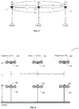
- FIG. 1 relates to a voltage sensing structure 10 according to an embodiment of the present disclosure.
- the voltage sensing structure 10 is utilized to sense the three-phase voltages of a high voltage electric power transmission system.
- the voltage sensing structure 10 comprises line voltage electrodes 100, 102, 104, ground potential electrodes 106, 108, 110 facing the line voltage electrodes 100, 102, 104, and field sensors 112, 114, 116.
- the line voltage electrodes 100, 102, and 104 are respectively coupled to power lines of line voltages VP1, VP2 and VP3.
- the line voltages VP1, VP2, VP3 are defined as the voltages relative to ground.
- the ground potential electrodes 106, 108, and 110 (in electric contact with ground) are configured at a distance l1 above the ground and the line voltage electrodes 100, 102, and 104, are configured at a distance l2 above the ground potential electrodes 106, 108, 116.
- the line voltage electrodes 100, 102, 104 and the ground potential electrodes 106, 108, 110 have disk-shaped bodies facing each others.
- the field sensors 112, 114 and 116 are respectively coupled (e.g. ohmically coupled) to the line voltage electrodes 100, 102 and 104 and configured to sense electric fields respectively at the line voltage electrodes 100, 102 and 104.
- the field sensor 112, 114, and 116 are configured to sense the electric fields at bottom sides of line voltage electrodes.
- the field sensor 112, 114 and 116 are configured to sense the electric fields in a vertical direction (e.g. from the ground to each of the line electrodes 100, 102, and 104).
- the field sensors 112, 114 and 116 are optical field sensors.
- the field sensors 112, 114 and 116 are configured to employ the electro-optical effect to sense the electric fields at the line voltage electrode 100, 102, 104. Based on the electrode fields sensed by the field sensors 112, 114 and 116, a voltage determining device (not shown in FIG. 1 ) is able to determine the line voltages VP1, VP2 and VP3.
- FIG. 2 relates to a schematic diagram of the sensitivity coefficients a ij according to an embodiment of the present disclosure.
- the sensitivity coefficient a 11 is the electric field effect from the difference between line potential VP1 and ground potential (i.e.
- the sensitivity coefficients a ij depend on relative positions of the line voltage electrodes 100, 102, 104 and the ground potential electrodes 106, 108, 110, shapes of the line voltage electrodes 100, 102, 104 and a permittivity ⁇ of the environment (the permittivity ⁇ is assumed as unity in this embodiment).
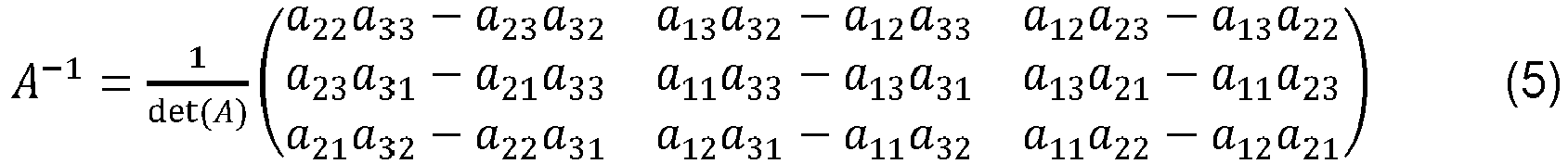
- matrix A -1 is the inverse matrix of the matrix A and can be expressed as:
- the sensitivity coefficients a ij may be determined by a calibration process or by electric field simulations.
- the field sensors 112, 114 and 116 may change to be configured on the ground potential electrodes 106, 108 and 110 and are configured to sense electric fields at the ground potential electrodes 106, 108 and 110, respectively.
- the line voltages VP1, VP2 and VP3 also change to be determined based on the electric fields sensed by the field sensors 112, 114 and 116 configured on the ground potential electrodes 106, 108 and 110 according to the equations (1) to (6).
- each of the field sensors mounted on the line voltage electrodes has 3 corresponding ground field sensors mounted on ground potential electrodes, wherein the 3 ground field sensors corresponding to the same field sensor are positioned respectively at 3 vertexes of an equilateral horizontal triangle whose center is beneath the corresponding field sensor.
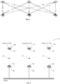
- FIG. 3 relates to a voltage sensing structure 30 according to an embodiment of the present disclosure.
- the voltage sensing structure 30 increases the number of field sensors to compensate changes in the relative positions among the field sensors and to maintain accuracy of the voltage sensing.
- the voltage sensing structure 30 comprises line voltage electrodes 300, 302, 304, ground potential electrodes 306, 308, 310 facing the line voltage electrodes 300, 302, 304, field sensors 312, 314, 316, and ground field sensors 318, 320, 322.
- the line voltage electrodes 300, 302, 304, the ground potential electrodes 306, 308, 310 and the field sensors 312, 314, 316 are similar to the line voltage electrodes 100, 102, 104, the ground potential electrodes 106, 108, 110 and the field sensors 112, 114, 116 shown in FIG. 1 .
- the line voltage electrodes 300, 302, 304 and the ground potential electrodes 306, 308, 310 are equipped with corona rings for field steering.
- ground potential electrodes 306, 308 and 310 are arranged at the distance l1 above the ground
- the line voltage electrodes 300, 302 and 304 are arranged at the distance l2 above the ground potential electrodes 306, 308 and 310
- the line voltage electrodes 300, 302, 304 and the ground potential electrodes 306, 308, 310 are horizontally arranged with an interval 13.
- three additional ground field sensors 318, 320 and 322 are configured on the ground potential electrodes 306, 308 and 310 and configured to sense electric fields at the ground potential electrodes 306, 308 and 310.
- the line voltages VP1, VP2 and VP3 of the three-phase voltages are determined based on the electric fields sensed by the field sensors 312, 314, 316 and the ground field sensors 318, 320, 322 and sensitivity coefficients corresponding to electric field effects from each of the line voltages VP1, VP2, VP3 to each of the field sensors 312, 314, 316 and the ground field sensors 318, 320, 322.
- the distances between each two field sensors may change due to, e.g., thermal expansion of mechanical structures for mounting the field sensors 312, 314, 316 and the ground field sensors 318, 320, 322 or forces (e.g. from wind) acting on the assembly.
- the using of more than 3 sensors as the voltage sensing structure 30 makes it possible to distinguish between signal changes caused by changes in the line voltages VP1, VP2 and VP3 from those caused by changes in sensor arrangement.
- the output signals of the field sensor 312 and the ground field sensor 318 will both change in proportion to the line voltage VP1. That is, the ratio between the output signals of the field sensor 312 and the ground field sensor 318 will remain unchanged.
- the line voltages VP1, VP2 and VP3 stay constant but the distance between the field sensor 312 and the ground field sensor 318 changes, the ratio of output signals of the field sensor 312 and the ground field sensor 318 will change.
- the ratio between the output signals of the field sensor 312 and the ground field sensor 318 changes in an inverse proportion to the distance between the field sensor 312 and the ground field sensor 318 (the position of field sensor 312 relative to the centers of the power lines remains unchanged in this example).
- changes in the lateral distances among the field sensors 312, 314 and 316 can be accounted for from changes in ratios among the output signals of the field sensors 312, 314, 316.
- FIG. 4 relates to schematic diagram of sensitivity coefficients a ij corresponding to the ground field sensors 318, 320 and 322 according to an embodiment of the present disclosure.
- sensitivity coefficients a ij may be dependent on other sensitivity coefficients and can be expressed by corresponded sensitivity coefficients so as to reduce the number of independent variables in the equations (4) to (6) and (9) to (11).
- the lateral positions of the line voltage electrodes 300, 302 and 304 may vary and the vertical separations between the line voltage electrodes 300, 302, and 304 and the ground potential electrodes 306, 308 and 310 (i.e.
- FIG. 5 relates to a voltage sensing structure 50 according to an embodiment of the present disclosure.
- the voltage sensing structure 50 adds floating field sensors 524, 526 and 528 which are configured respectively between the line electrode 500 and the ground potential electrode 506, between the line electrode 502 and the ground potential electrode 508 and between the line electrode 504 and the ground potential electrode 510.
- each of the floating field sensors 524, 526 and 528 are configured at a halfway position between the corresponding line voltage electrode and the ground potential electrode.
- the line voltages VP1, VP2 and VP3 of the three-phase voltages are determined according to the electric fields sensed by the field sensors 512, 514, 516, the ground field sensors 518, 520, 522 and the floating field sensors 524, 526, 528 and the sensitivity coefficients corresponding to electric field effects from each of the line voltages VP1, VP2, VP3 and each of the line voltages VP1, VP2 and VP3 of the three-phase voltages are determined according to the electric fields sensed by the field sensors 512, 514, 516, the ground field sensors 518, 520, 522 and the floating field sensors 524, 526, 528.
- FIG. 6 relates to a voltage sensing structure 60 according to an embodiment of the present disclosure.
- the number of the ground potential electrodes increases from 3 to 4.
- the voltage sensing structure 60 comprises high voltage electrodes 600, 602, 604, ground potential electrodes 606, 608, 610, 612, field sensors 614, 616, 618 mounted on the high voltage electrodes 600, 602 604 and the ground field sensors 620, 622, 624, 626 mounted on the ground potential electrodes 606, 608, 610, 612.
- the ground field sensors 620, 622, 624, 626 are horizontally displaced from the field sensors 614, 616 and 618 by half the lateral distance between the field sensors 614, 616 or the field sensors 616, 618.
- the line voltages VP1, VP2 and VP3 of the three-phase voltages are determined based on the electric fields sensed by the field sensors 614, 616, 618 and the ground field sensors 620, 622, 624, 626 and sensitivity coefficients corresponding to electric field effects from each of the line voltages VP1, VP2, VP3 to each of the field sensors 614, 616, 618 and the ground field sensors 620, 622, 624, 626.
- the arrangement shown in FIG. 6 is able to compensate an individual horizontal movement of each of the field sensors 614, 616 and 618.
- the ground potential electrodes 606 and 612 and the ground field sensors 620 and 626 on the ground potential electrodes 606 and 612 may be omitted. That is, the voltage sensing structure 60 may change to have 2 ground electrodes 608 and 610, which are configured between the line voltage electrodes 600 and 602 and between the line voltage electrodes 602 and 604, and the corresponding ground field sensors 622 and 624.
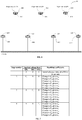
- FIG. 7 relates to a table of a calibration process according to an embodiment of the present disclosure.
- all of the line voltages VP1, VP2 and VP3 are set to 0 (i.e. the ground potential) and the output signals S1 to S6 of the field sensors (e.g. 312, 314 and 316) and the ground field sensors (e.g. 318, 320 and 322) are acquired as initial reference states at which all of the output signals S 1 to S 6 are zero.
- the line voltages VP1, VP2 and VP3 are sequentially set to a voltage potential V 0 which is a calibration voltage with amplitude V 0 while leaving remaining two line voltages on the ground potential.
- V 0 a voltage potential
- the line voltage VP1 is set to the voltage potential V0 and the line voltages VP2 and VP3 are on the ground potential
- a change in the output signal S 1 with respect to that of initial reference state acquired in the step 1 is acquired as the sensitivity coefficient a 11
- a change in the output signal S 4 with respect to that of initial reference state is acquired as the sensitivity coefficient a 41
- a change in the output signal S 2 with respect to that of initial reference state is acquired as the sensitivity coefficient a 21 , and so on.
- the calibration process shown in FIG. 7 may be implemented in an automated way.
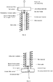
- FIGS. 8 and 9 relate to configurations of mounting a field sensor on a line voltage electrode and a ground field sensor on a ground potential electrode according to an embodiment of the present disclosure.
- the line voltage electrode and the ground potential electrode are connected by hollow core insulator (e.g. an insulator tube).
- the field sensor and the ground field sensor may be electro-optic field sensors, which consist of an electric field sensitive electro-optic element and sensor optics which may comprise polarizers, waveplates, beam splitters and collimators.
- the fiber cable comprises at least one optical fiber but may also consist of several fibers that carry light to and from a particular sensor.
- the line voltage electrode and ground potential electrode are attached to insulator flanges of a hollow core insulator.
- the field sensor and the ground field sensor are mounted in the insulator flanges (or the line voltage electrodes and the ground potential electrode).
- the electric field sensitive elements of the field sensor and the ground field sensor protrude into the electric fields at the outer surface of the insulator flanges.
- a fiber cable connects an opto-electronic unit (including a light source, photodetectors, and signal processing electronics, not shown in FIGS. 8 and 9 ) to the field sensor and the ground field sensor.
- the fiber cable enters the ground potential electrode from below.
- the fibers of the ground field sensor are split off from the cable within a fiber splice or connector box (not shown).
- the other fibers continue in a subsequent cable section through the hollow insulator to the line voltage electrode and the corresponding field sensor.
- the fibers passing through the hollow core insulator are not in a fiber cable but are bare fibers with only a primary coating or a buffer coating.
- the hollow volume of the hollow core insulator is filled with a high voltage proof filler material, e.g., compressible polyurethane foam or silicone gel. Another alternative is an insulating gas such as dry nitrogen.
- the field sensor and the ground field sensor protrude into the hollow core insulator.
- the insulator may be laterally displaced so that the field sensor and the ground field sensor protrude into environmental air.
- the field sensor and the ground field sensor shown in FIGS. 8 and 9 may change to other types of electric field sensor.
- the field sensor and the ground field sensor shown in FIGS. 8 and 9 may utilize piezoelectric transducer materials with optical interrogation to sense the electric fields at the line voltage electrode and the ground potential electrode.
- At least one floating field sensor may be configured into the hollow core insulator (e.g. an insulator tube) connecting the line voltage electrode and the ground potential electrode shown in FIGS. 8 and 9 .
- the floating field sensor 524 may be configured to the insulator tube connecting the line voltage electrode 500 and the ground potential electrode 506.
- the floating field sensor 526 may be configured to the insulator tube connecting the line voltage electrode 502 and the ground potential electrode 508, and the floating field sensor 526 may be configured to the insulator tube connecting the line voltage electrode 504 and the ground potential electrode 510.
- FIG. 10 relates to an arrangement of a field sensor and a corresponded ground field sensor according to an embodiment of the present disclosure.
- the field sensor and the corresponded ground field sensor e.g. the field sensor 312 and the ground field sensor 3148 are mounted at two ends of a (flexible or rigid) suspension insulator that holds the corresponding power line, e.g., at a location where the line enters into a substation.
- the suspension insulator carries the fiber connection to the sensor on the high voltage side of the insulator.
- FIG. 11 relates to a configuration of mounting the field sensor between two cylinder-shaped electrodes according to an embodiment of the present invention.
- the cylinder shaped electrodes are concentric with a power line of corresponding line voltage.
- the inner electrode is electrically contact with the power line and thus has the same potential as the power line.
- the outer electrode is on a floating potential.
- the field sensor measures the electric field between the inner electrode and the outer electrode, e.g., at the inner surface of the outer electrode.
- the arrangement shown in FIG. 11 may be designed as a "clamp-on mount" that can be attached to the power line without interrupting the power line. As a result, the field sensor can be well protected from the environment. The same or a similar arrangement may also be chosen for the ground field sensors.
- the inner electrode is then set to the ground potential.
- the inner electrode in FIG. 11 may be omitted. That is, the powerline represents the inner electrode.
Landscapes
- Physics & Mathematics (AREA)
- General Physics & Mathematics (AREA)
- Measuring Instrument Details And Bridges, And Automatic Balancing Devices (AREA)
Abstract
Description
- The invention relates to a voltage sensing structure for sensing a three-phase voltage of a high voltage electric power transmission system.
- Generally, power line alternating current (AC) voltages in electric power transmission and distribution grids are measured with inductive voltage transformers (VT) or capacitive voltage dividers (CVD). Particularly, resistive dividers or resistive/ capacitive dividers may be used when the power line AC voltages are lower. Due to their insulation requirements, the VT and CVD are relatively heavy, commonly oil-filled equipments, particularly at transmission voltages (typically when the power line AC voltages are in the range of hundreds of kilovolt). Other drawbacks of VT and CVD include the susceptibility to potentially hazardous ferro-resonances (VT) and limited accuracy at voltage transients.
- Optical voltage transducers eliminate a number of the deficits of the conventional instruments of measuring the power line AC voltage. However, known optical voltage transducers for outdoor air-insulated systems (AIS) still comprise a voluminous insulator column, resulting in that the physical size of an optical voltage transducer is not much different from the one of conventional transformers, even though being of smaller weight and utilizing a gas insulation or dry insulation to replace the oil insulation.
- Some recent works have focused on non-contact measurement of line voltages of the power lines. Some sensors are attempted to derive the line voltages by means of an array of generally capacitively coupled pick-up probes which may be located on the ground potential or are attached to the power lines. The measurement signals are transmitted from the power lines to the ground by optical fibers or wireless communications. This type of sensors offers ease of installation and robust high voltage insulation (without the need of an expensive insulator) but provide lower accuracy as the sensors are more susceptible to disturbances of the electric field distribution than conventional instruments. Also adjacent power lines may give rise to measurement uncertainties. Furthermore, the capacitive probes measure the time derivative of the electric field, and electric circuit parameters affect the frequency characteristic of the sensors.
- These and other objectives are achieved by a voltage sensing structure according to the independent claims. Preferred embodiments are evident from the dependent patent claims.
- The present invention relates to a voltage sensing structure for a three-phase power line system, the voltage sensing structure comprising a first field sensor configured to sense an electric field at a first line of voltage, a second field sensor configured to sense an electric field at a second line of voltage, a third field sensor configured to sense an electric field at a third line of voltage.
- Various embodiments may preferably implement the following features:
Preferably, the three-phase voltages are determined based on the electric fields sensed by the first field sensor, the second field sensor and the third field sensor and a plurality of sensitivity coefficients corresponding to electric field effects from each of the first line voltage, the second line voltage, and the third line voltage to each of the first field sensor, the second field sensor and the third field sensor. - Preferably, the voltage sensing structure further comprises at least one ground field sensor being configured to sense an electric field at a respective ground potential electrode.
- Preferably, the three-phase voltages are determined based on electric fields sensed by the first field sensor, the second field sensor, the third field sensor, and the at least one ground field sensor, and a plurality of sensitivity coefficients corresponding to electric field effects from each of the first line voltage, the second line voltage, and the third line voltage to each of the first field sensor, the second field sensor, the third field sensor and the at least one ground field sensor.
- Preferably, the voltage sensing structure further comprises a first line voltage electrode, coupled to the first power line of voltage of the three-phase power line system, a second line voltage electrode, coupled to the second power line of voltage of the three-phase power line system, a third line voltage electrode, coupled to the third power line of voltage of the three-phase power line system.
- Preferably, the first field sensor is coupled to the first line voltage electrode and is configured to sense the electric field at the first line voltage electrode, the second field sensor is coupled to the second line voltage electrode and is configured to sense the electric field at the second line voltage electrode, and the third field sensor is coupled to the third line voltage electrode and is configured to sense an electric field at the third line voltage electrode.
- Preferably, the at least one ground field sensor is configured to employ an electro-optical effect to sense an electric field at the ground potential electrode.
- Preferably, the first field sensor, the second field sensor and the third field sensor are optical field sensors.
- Preferably, the first field sensor, the second field sensor and the third field sensor are preferably configured to employ an electro-optical effect to sense the electric fields at the first line voltage electrode, the second line voltage electrode and the third line voltage electrode.
- Preferably, the first line voltage electrode is configured to steer the electric field in the vicinity of the first field sensor, the second line voltage electrode is configured to steer the electric field in the vicinity of the second field sensor, and the third line voltage electrode is configured to steer the electric in the vicinity of the third field sensor.
- Preferably, the first line voltage electrode, the second line voltage electrode and the third line voltage electrode are disk shaped so as to perform the field steering.
- Preferably, the at least one ground potential electrode is arranged at a first distance above the ground and the first line electrode, the second line voltage electrode and the third line voltage electrode are arranged at a second distance above the at least one ground potential electrode.
- Preferably, the voltage sensing structure comprises three ground field sensors and three respective ground potential electrodes.
- Preferably, each of the first line voltage electrode, the second line voltage electrode and the third line voltage electrode is connected to a respective ground potential electrode by an insulator tube containing at least one optical fiber of the respective field sensor coupled to the respectively connected line voltage electrode.
- Preferably, the voltage sensing structure comprises at least one floating field sensor, configured between at least one of the first line voltage electrode, the second line voltage electrode, and the third line voltage electrode and at least one ground potential electrode.
- Preferably, the three-phase voltages are determined based on electric fields sensed by the first field sensor, the second field sensor, the third field sensor, the at least one ground field sensor and the at least one floating field sensor, and a plurality of sensitivity coefficients corresponding to electric field effects from each of the first line voltage, the second line voltage, and the third line voltage to each of the first field sensor, the second field sensor, the third field sensor, the at least one ground potential sensor and the at least one floating field sensor.
- Preferably, the at least one floating field sensor is configured in an insulator tube connected to one of the first line voltage electrode, the second line voltage electrode and the third line voltage electrode and one of the at least one ground potential electrode.
- Preferably, the at least one ground potential electrode comprises a first ground potential electrode and a second ground potential electrode and the voltage sensing structure further comprising a plurality of ground field sensors.
- Preferably, the plurality of ground field sensors comprises a first ground field sensor, coupled to the first ground potential electrode and configured to sense an electric field at the first ground potential electrode.
- Preferably, the plurality of ground field sensors comprises a second ground field sensor, coupled to the second ground potential electrode and configured to sense an electric field at the second ground potential electrode.
- Preferably, the three-phase voltages are determined based on the electric fields sensed by the first field sensor, the second field sensor, the third field sensor, the first ground field sensor and the second ground field sensor and a plurality of sensitivity coefficients corresponding to electric field effects from each of the first line voltage, the second line voltage, and the third line voltage to each of the first field sensor, the second field sensor, the third field sensor, the first ground field sensor and the second ground field sensor.
- Preferably, the at least one ground potential electrode further comprises a third ground potential electrode and the plurality of ground field sensors further comprise a third ground field sensor, coupled to the third ground potential electrode and configured to sense an electric field at the third ground potential electrode.
- Preferably, the three-phase voltages are determined based on the electric fields sensed by the first field sensor, the second field sensor, the third field sensor, the first ground field sensor, the second ground field sensor and the third ground field sensor and a plurality of sensitivity coefficients corresponding to electric field effects from each of the first line voltage, the second line voltage, and the third line voltage to each of the first field sensor, the second field sensor, the third field sensor, the first ground field sensor, the second ground field sensor and the third ground field sensor.
- Preferably, the at least one ground potential electrode further comprises a fourth ground potential electrode and wherein the at least one ground field sensor further comprises a fourth ground field sensor, coupled to the fourth ground potential electrode and configured to sense an electric field at the fourth ground potential electrode.
- Preferably, the three-phase voltages are determined based on electric fields sensed by the first field sensor, the second field sensor, the third field sensor, the first ground field sensor, the second ground field sensor, the third ground field sensor and the fourth ground field sensor and a plurality of sensitivity coefficients corresponding to electric field effects from each of the first line voltage, the second line voltage, the third line voltage to each of the first field sensor, the second field sensor, the third field sensor, the first ground field sensor, the second ground field sensor, the third ground field sensor and the fourth ground field sensor.
- Preferably, the plurality of sensitivity coefficients are determined from the signals of the first field sensor, the second field sensor and the third field sensor when at least two of the first line voltage, the second line voltage and the third line voltage are at ground potential and the remaining of the first line voltage, the second line voltage and the third line voltage is a calibration voltage.
- Preferably, the plurality of sensitivity coefficients is determined by electric field simulations.
- Preferably, the three-phase voltages are three-phase voltages of a high voltage electric power transmission system.
- The present invention also relates to a voltage sensing structure for a three-phase power line system, the voltage sensing structure comprising a first ground field sensor configured to sense an electric field at a first ground potential electrode coupled to the ground potential, a second ground field sensor configured to sense an electric field at a second ground potential electrode coupled to the ground potential, and a third ground field sensor configured to sense an electric field at a third ground potential electrode coupled to the ground potential, wherein the three-phases voltages are determined based on the electric fields sensed by the first ground field sensor, the second ground field sensor and the third ground field sensor and a plurality of sensitivity coefficients corresponding to electric field effects from each of a first line voltage of a three-phase voltage, the second line voltage of the three-phase voltage, the third line voltage of the three-phase voltage to each of the first ground field sensor, the second ground field sensor and the third ground field sensor.
- Preferably, the first ground field sensor, the second ground field sensor and the third ground field sensor are optical field sensors.
- Preferably, the first ground field sensor, the second ground field sensor and the third ground field sensor are configured to employ the electro-optical effect to sense the electric fields at the first ground potential electrode, the second ground potential electrode and the third ground potential electrode.
- Preferably, the first ground potential electrode, the second ground potential electrode and the third ground potential electrode are arranged at a first distance above the ground and the first line voltage electrode, the second line voltage electrode and the third line voltage electrode are arranged at a second distance above the first ground potential electrode, the second ground potential electrode and the third ground potential electrode.
- Preferably, the first line voltage electrode is connected to the first ground potential electrode by a first insulator tube, the second line voltage electrode is connected to the second ground potential electrode by a second insulator tube, and the third line voltage electrode is connected to the third ground potential electrode by a third insulator tube.
- Preferably, the plurality of sensitivity coefficients are determined from the signals of the first ground field sensor, the second ground field sensor and the third ground field sensor when at least two of the first line voltage, the second line voltage and the third line voltage are at the ground level and the remaining of the first line voltage, the second line voltage and the third line voltage is a calibration voltage.
- Preferably, the three-phase voltages constitute three-phase voltages of a high voltage electric power transmission system.
- The present invention also relates to a method for voltage sensing at a three-phase power line system, the method comprising sensing an electric field at a first line of voltage with a first field sensor; sensing an electric field at a second line of voltage with a second field sensor; sensing an electric field at a third line of voltage with a third field sensor. The method preferably comprises determining the three-phase voltages based on the electric fields sensed by the first field sensor, the second field sensor and the third field sensor and a plurality of sensitivity coefficients corresponding to electric field effects from each of the first line voltage, the second line voltage, and the third voltage to each of the first field sensor, the second field sensor and the third field sensor.
- The present invention also relates to a voltage sensing structure for a three-phase power line system, the voltage sensing structure comprising a first line voltage electrode, coupled to a first line of voltage, a second line voltage electrode coupled to a second line of voltage, a third line voltage electrode coupled to a third line of voltage of the three-phase voltages, a first ground potential electrode, coupled to the ground potential, a second ground potential electrode coupled to the ground potential, a third ground potential electrode, coupled to the ground potential, a first floating field sensor, configured between the first line voltage electrode and the first ground potential electrode, a second floating field sensor, configured between the second line voltage electrode and the second ground potential electrode, and a third floating field sensor configured between the third line voltage electrode and the third ground potential electrode, wherein the three-phase voltages are determined based on electric fields sensed by the first floating field sensor, the second floating field sensor and the third floating field sensor and a plurality of sensitivity coefficients corresponding to electric field effects from each of the first line voltage, the second line voltage, the third line voltage to each of the first floating field sensor, the second floating field sensor and the third floating field sensor.
- Preferably, the first floating field sensor, the second floating field sensor and the third floating field sensor are optical field sensors.
- Preferably, the first floating field sensor, the second floating field sensor and the third floating field sensor are configured to employ the electro-optical effect to sense the electric fields of determining the three-phase voltages.
- Preferably, the first line voltage electrode, the second line voltage electrode, the third line voltage electrode, the first ground potential electrode, the second ground potential electrode and the third ground potential electrode are disk-shaped bodies facing each others.
- Preferably, the plurality of sensitivity coefficients are determined from the signals of the first floating field sensor, the second floating field sensor and the third floating field sensor when at least two of the first line voltage, the second line voltage and the third line voltage are at the ground level and the remaining of the first line voltage, the second line voltage and the third line voltage is a calibration voltage.
- The subject matter of the invention will be explained in more detail in the following text with reference to preferred exemplary embodiments which are illustrated in the attached drawings, in which:
-
FIG. 1 schematically shows a voltage sensing structure according to an embodiment of the present disclosure. -
FIG. 2 schematically shows sensitivity coefficients according to an embodiment of the present disclosure. -
FIG. 3 schematically shows a voltage sensing structure according to an embodiment of the present disclosure. -
FIG. 4 schematically shows sensitivity coefficients according to an embodiment of the present disclosure. -
FIG. 5 schematically shows a voltage sensing structure according to an embodiment of the present disclosure. -
FIG. 6 schematically shows a voltage sensing structure according to an embodiment of the present disclosure. -
FIG. 7 schematically shows a table of a calibration process according to an embodiment of the present disclosure. -
FIG. 8 schematically shows a configuration of mounting a field sensor on a line voltage electrode according to an embodiment of the present disclosure. -
FIG. 9 schematically shows a configuration of mounting a ground field sensor on a ground potential electrode according to an embodiment of the present disclosure. -
FIG. 10 schematically shows an arrangement of a field sensor and a corresponded ground field sensor according to an embodiment of the present disclosure. -
FIG. 11 schematically shows a configuration of mounting the field sensor between two cylinder-shaped electrodes according to an embodiment of the present invention. - The reference symbols used in the drawings, and their primary meanings, are listed in summary form in the list of designations. In principle, identical parts are provided with the same reference symbols in the figures.
-
FIG. 1 relates to avoltage sensing structure 10 according to an embodiment of the present disclosure. Thevoltage sensing structure 10 is utilized to sense the three-phase voltages of a high voltage electric power transmission system. As shown inFIG. 1 , thevoltage sensing structure 10 comprisesline voltage electrodes potential electrodes line voltage electrodes field sensors line voltage electrodes potential electrodes line voltage electrodes potential electrodes line voltage electrodes potential electrodes - The
field sensors line voltage electrodes line voltage electrodes field sensor field sensor line electrodes field sensors field sensors line voltage electrode field sensors FIG. 1 ) is able to determine the line voltages VP1, VP2 and VP3. - In detail, the line voltages VP1, VP2 and VP3 may be obtained according to the electrode fields sensed by the
field sensors field sensors FIG. 2 relates to a schematic diagram of the sensitivity coefficients aij according to an embodiment of the present disclosure. As shown inFIG. 2 , the sensitivity coefficient a11 is the electric field effect from the difference between line potential VP1 and ground potential (i.e. from line voltage VP1), a12 is the electric field effect from the line voltage VP2 to thefield sensor 112, a13 is the electric field effect from the line voltage VP3 to thefield sensor 112, and so on. Based onFIG. 2 , instantaneous values of the output signals S1, S2 and S3 of thefield sensors 


line voltage electrodes potential electrodes line voltage electrodes 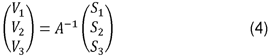

- The sensitivity coefficients aij may be determined by a calibration process or by electric field simulations.
- In an embodiment, the
field sensors potential electrodes potential electrodes field sensors potential electrodes - Note that, the number of the ground potential electrodes varies based on different design concepts and requirements and even can be zero, i.e., ground itself becomes the common "electrode" for all three power lines. In an embodiment, each of the field sensors mounted on the line voltage electrodes has 3 corresponding ground field sensors mounted on ground potential electrodes, wherein the 3 ground field sensors corresponding to the same field sensor are positioned respectively at 3 vertexes of an equilateral horizontal triangle whose center is beneath the corresponding field sensor.
-
FIG. 3 relates to avoltage sensing structure 30 according to an embodiment of the present disclosure. In comparison with thevoltage sensing structure 10, thevoltage sensing structure 30 increases the number of field sensors to compensate changes in the relative positions among the field sensors and to maintain accuracy of the voltage sensing. - In detail, the
voltage sensing structure 30 comprisesline voltage electrodes potential electrodes line voltage electrodes field sensors ground field sensors line voltage electrodes potential electrodes field sensors line voltage electrodes potential electrodes field sensors FIG. 1 . InFIG. 3 , theline voltage electrodes potential electrodes potential electrodes line voltage electrodes potential electrodes line voltage electrodes potential electrodes - In this embodiment, three additional
ground field sensors potential electrodes potential electrodes field sensors ground field sensors field sensors ground field sensors - Practically, the distances between each two field sensors may change due to, e.g., thermal expansion of mechanical structures for mounting the
field sensors ground field sensors voltage sensing structure 30 makes it possible to distinguish between signal changes caused by changes in the line voltages VP1, VP2 and VP3 from those caused by changes in sensor arrangement. - For example, if the line voltage VP1 changes and all distances between each two of the
field sensors ground field sensors field sensor 312 and theground field sensor 318 will both change in proportion to the line voltage VP1. That is, the ratio between the output signals of thefield sensor 312 and theground field sensor 318 will remain unchanged. On the other hand, if the line voltages VP1, VP2 and VP3 stay constant but the distance between thefield sensor 312 and theground field sensor 318 changes, the ratio of output signals of thefield sensor 312 and theground field sensor 318 will change. In an example assuming the electric field around the power lines of line voltage VP1, VP2 and VP3 are cylinder-symmetric electric fields, which fall off inversely proportional to the distance from the line, the ratio between the output signals of thefield sensor 312 and theground field sensor 318 changes in an inverse proportion to the distance between thefield sensor 312 and the ground field sensor 318 (the position offield sensor 312 relative to the centers of the power lines remains unchanged in this example). In a similar manner, changes in the lateral distances among thefield sensors field sensors - Details of utilizing the output signals S1, S2, S3 of the
field sensors FIG. 2 , the equations (1) to (5) and related descriptions and are not described herein for brevity.FIG. 4 relates to schematic diagram of sensitivity coefficients aij corresponding to theground field sensors ground field sensors 

- According to equations (7) and (8), the instantaneous values V1, V2 and V3 of the line voltages VP1, VP2 and VP3 can be determined by:


- According to the equations (4) to (6) and (9) to (11), the three instantaneous values V1, V2 and V3 of the line voltages VP1, VP2 and VP3 are derived from the output signals S1 to S6 of the
field sensors ground field sensors field sensors ground field sensors 


- Note that only changes in the coefficient a20 are taken into account to recalculate the less critical sensitivity coefficients a51, a42, a53, a62, a61 and a43 (corresponding to diagonal dashed lines in
FIG. 4 ) which describe the effects of the respective adjacent line voltages on theground field sensors - In order to enhance a robustness of a voltage sensing structure, additional sensors may be added at appropriate positions in the voltage sensing structure of the present disclosure. In an embodiment, at least one floating field sensor may be configured between at least one of line voltage electrodes (e.g. 300, 302 and 304) and corresponded ground potential electrode (e.g. 306, 308 or 310).
FIG. 5 relates to avoltage sensing structure 50 according to an embodiment of the present disclosure. In comparison with thevoltage sensing structure 30, thevoltage sensing structure 50 adds floatingfield sensors line electrode 500 and the groundpotential electrode 506, between theline electrode 502 and the groundpotential electrode 508 and between theline electrode 504 and the groundpotential electrode 510. In this embodiment, each of the floatingfield sensors field sensors ground field sensors field sensors field sensors ground field sensors field sensors -
FIG. 6 relates to avoltage sensing structure 60 according to an embodiment of the present disclosure. In this embodiment, the number of the ground potential electrodes increases from 3 to 4. As shown inFIG. 6 , thevoltage sensing structure 60 compriseshigh voltage electrodes potential electrodes field sensors high voltage electrodes ground field sensors potential electrodes ground field sensors field sensors field sensors field sensors field sensors ground field sensors field sensors ground field sensors FIG. 6 is able to compensate an individual horizontal movement of each of thefield sensors - In an embodiment, the ground
potential electrodes ground field sensors potential electrodes voltage sensing structure 60 may change to have 2ground electrodes line voltage electrodes line voltage electrodes ground field sensors -
FIG. 7 relates to a table of a calibration process according to an embodiment of the present disclosure. The calibration process shown inFIG. 7 is utilized to determine the sensitivity coefficients aij (i= 1, 2, 3, ... , 6 and j = 1, 2, 3) shown inFIG. 2 andFIG. 4 . According to the table shown inFIG. 7 , all of the line voltages VP1, VP2 and VP3 are set to 0 (i.e. the ground potential) and the output signals S1 to S6 of the field sensors (e.g. 312, 314 and 316) and the ground field sensors (e.g. 318, 320 and 322) are acquired as initial reference states at which all of the output signals S1 to S6 are zero. Next, the line voltages VP1, VP2 and VP3 are sequentially set to a voltage potential V0 which is a calibration voltage with amplitude V0 while leaving remaining two line voltages on the ground potential. When the line voltage VP1 is set to the voltage potential V0 and the line voltages VP2 and VP3 are on the ground potential, a change in the output signal S1 with respect to that of initial reference state acquired in thestep 1 is acquired as the sensitivity coefficient a11, a change in the output signal S4 with respect to that of initial reference state is acquired as the sensitivity coefficient a41, a change in the output signal S2 with respect to that of initial reference state is acquired as the sensitivity coefficient a21, and so on. Similarly, when the line voltage VP2 is set to the voltage potential V0 and the line voltages VP1 and VP3 are set to the ground potential, a change in the output signal S2 with respect to that of initial reference state acquired in thestep 1 is acquired as the sensitivity coefficient a22, a change in the output signal S5 with respect to that of initial reference state is acquired as the sensitivity coefficient a52, a change in the output signal S1 with respect to that of initial reference state is acquired as the sensitivity coefficient a12, and so on. In addition, when the line voltage VP3 is set to the voltage potential V0 and the line voltages VP1 and VP2 are set to the ground potential, a change in the output signal S3 with respect to that of initial reference state acquired in thestep 1 is acquired as the sensitivity coefficient a33, a change in the output signal S6 with respect to that of initial reference state is acquired as the sensitivity coefficient a63, a change in the output signal S1 with respect to that of initial reference state is acquired as the sensitivity coefficient a13, and so on. - Furthermore, when all of the sensitivity coefficients aij (i = 1, 2, 3, ... , 6 and j = 1, 2, 3) are determined, the fixed constant coefficients αk (k= 0, 1, 2, 3, ... , 6) also can be determined.
- In an embodiment, the calibration process shown in
FIG. 7 may be implemented in an automated way. -
FIGS. 8 and 9 relate to configurations of mounting a field sensor on a line voltage electrode and a ground field sensor on a ground potential electrode according to an embodiment of the present disclosure. As shown inFIGS. 8 and 9 , the line voltage electrode and the ground potential electrode are connected by hollow core insulator (e.g. an insulator tube). - In this embodiment, the field sensor and the ground field sensor may be electro-optic field sensors, which consist of an electric field sensitive electro-optic element and sensor optics which may comprise polarizers, waveplates, beam splitters and collimators. The fiber cable comprises at least one optical fiber but may also consist of several fibers that carry light to and from a particular sensor. The line voltage electrode and ground potential electrode are attached to insulator flanges of a hollow core insulator. The field sensor and the ground field sensor are mounted in the insulator flanges (or the line voltage electrodes and the ground potential electrode). The electric field sensitive elements of the field sensor and the ground field sensor protrude into the electric fields at the outer surface of the insulator flanges. The remaining sensor optics are inside the insulator flanges. A fiber cable connects an opto-electronic unit (including a light source, photodetectors, and signal processing electronics, not shown in
FIGS. 8 and 9 ) to the field sensor and the ground field sensor. InFIG. 9 , the fiber cable enters the ground potential electrode from below. The fibers of the ground field sensor are split off from the cable within a fiber splice or connector box (not shown). The other fibers continue in a subsequent cable section through the hollow insulator to the line voltage electrode and the corresponding field sensor. Alternatively, the fibers passing through the hollow core insulator are not in a fiber cable but are bare fibers with only a primary coating or a buffer coating. The hollow volume of the hollow core insulator is filled with a high voltage proof filler material, e.g., compressible polyurethane foam or silicone gel. Another alternative is an insulating gas such as dry nitrogen. - In
FIGS. 8 and 9 , the field sensor and the ground field sensor protrude into the hollow core insulator. Alternatively, the insulator may be laterally displaced so that the field sensor and the ground field sensor protrude into environmental air. - In an embodiment, the field sensor and the ground field sensor shown in
FIGS. 8 and 9 may change to other types of electric field sensor. For example, the field sensor and the ground field sensor shown inFIGS. 8 and 9 may utilize piezoelectric transducer materials with optical interrogation to sense the electric fields at the line voltage electrode and the ground potential electrode. - In an embodiment, at least one floating field sensor may be configured into the hollow core insulator (e.g. an insulator tube) connecting the line voltage electrode and the ground potential electrode shown in
FIGS. 8 and 9 . For example, the floatingfield sensor 524 may be configured to the insulator tube connecting theline voltage electrode 500 and the groundpotential electrode 506. Similarly, the floatingfield sensor 526 may be configured to the insulator tube connecting theline voltage electrode 502 and the groundpotential electrode 508, and the floatingfield sensor 526 may be configured to the insulator tube connecting theline voltage electrode 504 and the groundpotential electrode 510. -
FIG. 10 relates to an arrangement of a field sensor and a corresponded ground field sensor according to an embodiment of the present disclosure. InFIG. 10 , the field sensor and the corresponded ground field sensor (e.g. thefield sensor 312 and the ground field sensor 318) are mounted at two ends of a (flexible or rigid) suspension insulator that holds the corresponding power line, e.g., at a location where the line enters into a substation. The suspension insulator carries the fiber connection to the sensor on the high voltage side of the insulator. -
FIG. 11 relates to a configuration of mounting the field sensor between two cylinder-shaped electrodes according to an embodiment of the present invention. InFIG. 11 , the cylinder shaped electrodes are concentric with a power line of corresponding line voltage. The inner electrode is electrically contact with the power line and thus has the same potential as the power line. The outer electrode is on a floating potential. The field sensor measures the electric field between the inner electrode and the outer electrode, e.g., at the inner surface of the outer electrode. The arrangement shown inFIG. 11 may be designed as a "clamp-on mount" that can be attached to the power line without interrupting the power line. As a result, the field sensor can be well protected from the environment. The same or a similar arrangement may also be chosen for the ground field sensors. The inner electrode is then set to the ground potential. - Note that, the inner electrode in
FIG. 11 may be omitted. That is, the powerline represents the inner electrode. -
- 10, 30, 50, 60
Voltage sensing structure - 100, 102, 104, 300, 302, 304, 500, 502, 504, 600, 602, 604
Line voltage electrodes - 106, 108, 110, 306, 308, 310, 506, 508, 510, 606, 608, 610, 612
Ground potential electrodes - 112, 114, 116, 312, 314, 316, 614, 616, 618
Field sensors - 318, 320, 322, 518, 520, 522, 620, 622, 624, 626
Ground field sensors - 524, 526, 528
Floating field sensors - VP1, VP2, VP3
Line voltages
Claims (14)
- A voltage sensing structure for a three-phase power line system, comprising:a first field sensor (112) configured to sense an electric field at a first line of voltage (VP1),a second field sensor (114) configured to sense an electric field at a second line of voltage (VP2),a third field sensor (116) configured to sense an electric field at a third line of voltage (VP3), andat least one ground field sensor being configured to sense an electric field at a respective ground potential electrode,wherein the three-phase voltages (VP1, VP2, VP3) are determined based on electric fields sensed by the first field sensor (312), the second field sensor (314), the third field sensor (316), and the at least one ground field sensor, and a plurality of sensitivity coefficients corresponding to electric field effects from each of the first line voltage (VP1), the second line voltage (VP2), and the third line voltage (VP3) to each of the first field sensor (312), the second field sensor (314), the third field sensor (316) and the at least one ground field sensor.
- The voltage sensing structure of claim 1, further comprising:a first line voltage electrode (100), coupled to the first power line of voltage (VP1) of the three-phase power line system,a second line voltage electrode (102), coupled to the second power line of voltage (VP2) of the three-phase power line system,a third line voltage electrode (104), coupled to the third power line of voltage (VP3) of the three-phase power line system,wherein the first field sensor (112) is coupled to the first line voltage electrode and is configured to sense the electric field at the first line voltage electrode (100), the second field sensor (114) is coupled to the second line voltage electrode and is configured to sense the electric field at the second line voltage electrode (102), and the third field sensor (116) is coupled to the third line voltage electrode and is configured to sense an electric field at the third line voltage electrode (104).
- The voltage sensing structure of claim 1 or 2, wherein the at least one ground field sensor being configured to employ an electro-optical effect to sense an electric field at the ground potential electrode.
- The voltage sensing structure of claim 2 or 3, wherein the first field sensor (112), the second field sensor (114) and the third field sensor (116) are optical field sensors and wherein the first field sensor (112), the second field sensor (114) and the third field sensor (116) are preferably configured to employ an electro-optical effect to sense the electric fields at the first line voltage electrode (100), the second line voltage electrode (102) and the third line voltage electrode (104).
- The voltage sensing structure of any one of claims 2 to 4, wherein the first line voltage electrode (100) is configured to steer the electric field in the vicinity of the first field sensor (112), the second line voltage electrode (102) is configured to steer the electric field in the vicinity of the second field sensor (114), and the third line voltage electrode (104) is configured to steer the electric in the vicinity of the third field sensor (116) and/or
wherein the first line voltage electrode (100), the second line voltage electrode (102) and the third line voltage electrode (104) are disk shaped so as to perform the field steering. - The voltage sensing structure of any of claims 1 to 5, wherein the at least one ground potential electrode is arranged at a first distance (11) above the ground and the first line electrode (100), the second line voltage electrode (102) and the third line voltage electrode (104) are arranged at a second distance (12) above the at least one ground potential electrode.
- The voltage sensing structure of any of claims 1 to 6, comprising three ground field sensors and three respective ground potential electrodes, wherein preferably each of the first line voltage electrode (100), the second line voltage electrode (102) and the third line voltage electrode (104) is connected to a respective ground potential electrode by an insulator tube containing at least one optical fiber of the respective field sensor coupled to the respectively connected line voltage electrode.
- The voltage sensing structure of any of claims 2 to 7, further comprising:at least one floating field sensor, configured between at least one of the first line voltage electrode (100), the second line voltage electrode (102), and the third line voltage electrode (104) and at least one ground potential electrode,wherein the three-phase voltages are determined based on electric fields sensed by the first field sensor (512), the second field sensor (514), the third field sensor (516), the at least one ground field sensor and the at least one floating field sensor, and a plurality of sensitivity coefficients corresponding to electric field effects from each of the first line voltage (VP1), the second line voltage (VP2), and the third line voltage (VP3) to each of the first field sensor (512), the second field sensor (514), the third field sensor (516), the at least one ground potential sensor and the at least one floating field sensor.
- The voltage sensing structure of claim 8, wherein the at least one floating field sensor is configured in an insulator tube connected to one of the first line voltage electrode (100), the second line voltage electrode (102) and the third line voltage electrode (104) and one of the at least one ground potential electrode.
- The voltage sensing structure of any of claims 1 to 9, wherein the plurality of sensitivity coefficients are determined from the signals of the first field sensor (112), the second field sensor (114) and the third field sensor (116) when at least two of the first line voltage (VP1), the second line voltage (VP2) and the third line voltage (VP3) are at ground potential and the remaining of the first line voltage (VP1), the second line voltage (VP2) and the third line voltage (VP3) is a calibration voltage.
- The voltage sensing structure of any of claims 1 to 10, wherein the plurality of sensitivity coefficients is determined by electric field simulations.
- The voltage sensing structure of any of claims 1 to 11, wherein the three-phase voltages are three-phase voltages of a high voltage electric power transmission system.
- A voltage sensing structure for a three-phase power line system comprising:a first ground field sensor configured to sense an electric field at a first ground potential electrode (106) coupled to the ground potential,a second ground field sensor configured to sense an electric field at a second ground potential electrode (108) coupled to the ground potential, anda third ground field sensor configured to sense an electric field at a third ground potential electrode (110) coupled to the ground potential,wherein the three-phases voltages (VP1, VP2, VP3) are determined based on the electric fields sensed by the first ground field sensor, the second ground field sensor and the third ground field sensor and a plurality of sensitivity coefficients corresponding to electric field effects from each of a first line voltage (VP1) of three-phase voltages, the second line voltage (VP2) of three-phase voltages, the third line voltage (VP3) of three-phase voltages to each of the first ground field sensor, the second ground field sensor and the third ground field sensor.
- A method for voltage sensing at a three-phase power line system, comprising:sensing an electric field at a first line of voltage (VP1) with a first field sensor (112);sensing an electric field at a second line of voltage (VP2) with a second field sensor (114);sensing an electric field at a third line of voltage (VP3) with a third field sensor (116);sensing an electric field at a ground potential electrode with at least one ground field sensordetermining the three-phase voltages (VP1, VP2, VP3) based on electric fields sensed by the first field sensor (312), the second field sensor (314), the third field sensor (316), and the at least one ground field sensor, and a plurality of sensitivity coefficients corresponding to electric field effects from each of the first line voltage (VP1), the second line voltage (VP2), and the third line voltage (VP3) to each of the first field sensor (312), the second field sensor (314), the third field sensor (316) and the at least one ground field sensor.
Applications Claiming Priority (1)
| Application Number | Priority Date | Filing Date | Title |
|---|---|---|---|
| EP19190751 | 2019-08-08 |
Publications (1)
| Publication Number | Publication Date |
|---|---|
| EP3772653A1 true EP3772653A1 (en) | 2021-02-10 |
Family
ID=67587496
Family Applications (1)
| Application Number | Title | Priority Date | Filing Date |
|---|---|---|---|
| EP20189839.2A Withdrawn EP3772653A1 (en) | 2019-08-08 | 2020-08-06 | Voltage sensing structure |
Country Status (1)
| Country | Link |
|---|---|
| EP (1) | EP3772653A1 (en) |
Cited By (3)
| Publication number | Priority date | Publication date | Assignee | Title |
|---|---|---|---|---|
| CN114563619A (en) * | 2022-04-06 | 2022-05-31 | 南方电网数字电网研究院有限公司 | Anti-interference non-contact voltage measurement method and device based on electric field sensing chip |
| CN114778924A (en) * | 2022-06-21 | 2022-07-22 | 华中科技大学 | Three-phase voltage non-contact measurement method and system, electronic device and storage medium |
| CN115166339A (en) * | 2022-09-08 | 2022-10-11 | 华中科技大学 | Three-phase voltage non-contact measurement method based on field decomposition-collaborative search |
Citations (7)
| Publication number | Priority date | Publication date | Assignee | Title |
|---|---|---|---|---|
| EP0337265A1 (en) * | 1988-04-12 | 1989-10-18 | Maschinenfabrik Reinhausen Gmbh | Correcting process for voltage measuring in a three-phase system |
| FR2782169A1 (en) * | 1998-08-05 | 2000-02-11 | Alstom Technology | A system for measuring the voltage in an overhead power cable from a position on the earth is by measurement of the cable's electric field using electrodes placed at ground level |
| US6252388B1 (en) * | 1998-12-04 | 2001-06-26 | Nxtphase Corporation | Method and apparatus for measuring voltage using electric field sensors |
| US20050286190A1 (en) * | 2004-06-29 | 2005-12-29 | Rostron Joseph R | Electric power monitoring and response system |
| EP2577328A1 (en) * | 2010-06-07 | 2013-04-10 | ABB Research Ltd. | High-voltage sensor with axially overlapping electrodes |
| US9880217B1 (en) * | 2014-03-06 | 2018-01-30 | Harris Corporation | Measuring line characteristics of three-phase power transmission lines |
| CN108919158A (en) * | 2018-07-17 | 2018-11-30 | 国网四川省电力公司电力科学研究院 | The field calibration method of AC Substation transient voltage non-contact measurement apparatus |
-
2020
- 2020-08-06 EP EP20189839.2A patent/EP3772653A1/en not_active Withdrawn
Patent Citations (7)
| Publication number | Priority date | Publication date | Assignee | Title |
|---|---|---|---|---|
| EP0337265A1 (en) * | 1988-04-12 | 1989-10-18 | Maschinenfabrik Reinhausen Gmbh | Correcting process for voltage measuring in a three-phase system |
| FR2782169A1 (en) * | 1998-08-05 | 2000-02-11 | Alstom Technology | A system for measuring the voltage in an overhead power cable from a position on the earth is by measurement of the cable's electric field using electrodes placed at ground level |
| US6252388B1 (en) * | 1998-12-04 | 2001-06-26 | Nxtphase Corporation | Method and apparatus for measuring voltage using electric field sensors |
| US20050286190A1 (en) * | 2004-06-29 | 2005-12-29 | Rostron Joseph R | Electric power monitoring and response system |
| EP2577328A1 (en) * | 2010-06-07 | 2013-04-10 | ABB Research Ltd. | High-voltage sensor with axially overlapping electrodes |
| US9880217B1 (en) * | 2014-03-06 | 2018-01-30 | Harris Corporation | Measuring line characteristics of three-phase power transmission lines |
| CN108919158A (en) * | 2018-07-17 | 2018-11-30 | 国网四川省电力公司电力科学研究院 | The field calibration method of AC Substation transient voltage non-contact measurement apparatus |
Non-Patent Citations (1)
| Title |
|---|
| KE ZHU ET AL: "Non-Contact Capacitive-Coupling-Based and Magnetic-Field-Sensing-Assisted Technique for Monitoring Voltage of Overhead Power Transmission Lines", IEEE SENSORS JOURNAL., vol. 17, no. 4, 15 February 2017 (2017-02-15), US, pages 1069 - 1083, XP055754981, ISSN: 1530-437X, DOI: 10.1109/JSEN.2016.2636862 * |
Cited By (5)
| Publication number | Priority date | Publication date | Assignee | Title |
|---|---|---|---|---|
| CN114563619A (en) * | 2022-04-06 | 2022-05-31 | 南方电网数字电网研究院有限公司 | Anti-interference non-contact voltage measurement method and device based on electric field sensing chip |
| CN114563619B (en) * | 2022-04-06 | 2023-02-17 | 南方电网数字电网研究院有限公司 | Anti-interference non-contact voltage measurement method and device based on electric field sensing chip |
| CN114778924A (en) * | 2022-06-21 | 2022-07-22 | 华中科技大学 | Three-phase voltage non-contact measurement method and system, electronic device and storage medium |
| CN115166339A (en) * | 2022-09-08 | 2022-10-11 | 华中科技大学 | Three-phase voltage non-contact measurement method based on field decomposition-collaborative search |
| CN115166339B (en) * | 2022-09-08 | 2023-01-03 | 华中科技大学 | Three-phase voltage non-contact measurement method based on field decomposition-collaborative search |
Similar Documents
| Publication | Publication Date | Title |
|---|---|---|
| EP1137950B1 (en) | Voltage sensor | |
| EP3772653A1 (en) | Voltage sensing structure | |
| RU2567404C2 (en) | High-voltage sensor with electrodes overlapping electrodes along axis | |
| Christensen | Design, construction, and test of a passive optical prototype high voltage instrument transformer | |
| US6380725B1 (en) | Voltage sensor | |
| CN201051119Y (en) | Distributed optical voltage mutual inductor | |
| Ma et al. | A MEMS-based electric field sensor for measurement of high-voltage DC synthetic fields in air | |
| KR20170094412A (en) | Optoelectric measuring device and method for measuring an electrical current | |
| US9810728B2 (en) | Voltage measuring device | |
| US20040239307A1 (en) | Temperature-compensated electro-optical voltage sensor | |
| US10281498B2 (en) | Intensity modulated fiber optic voltage sensors for alternating current and direct current power systems | |
| EP0834078A1 (en) | High voltage measuring device | |
| EP2577328B1 (en) | High-voltage sensor with axially overlapping electrodes | |
| Källstrand et al. | Measurements of high voltage DC fields in air | |
| US4507603A (en) | Apparatus for the measurement of the movement of a member horizontally relative to a datum | |
| JP2010068665A (en) | Optical voltage measuring apparatus | |
| CN101278201A (en) | Voltage sensor and voltage sensing method for gas-insulated switchgear | |
| JP2722749B2 (en) | Zero-phase voltage detector | |
| KR100848681B1 (en) | Optical current sensor installation device | |
| JPWO2020152820A1 (en) | Voltage measuring device and gas insulated switchgear | |
| JP2932770B2 (en) | Distribution line monitoring device | |
| RU2184380C1 (en) | Accelerometer of compensation type | |
| JP2000155137A (en) | Optical transformer and transformer for optical conversion type instrument | |
| SU1679412A1 (en) | Method for checking of status of grounding rods of supports of aerial power lines without disconnection of overhead ground-wire cable | |
| JPS6217663A (en) | Voltage/current detector |
Legal Events
| Date | Code | Title | Description |
|---|---|---|---|
| PUAI | Public reference made under article 153(3) epc to a published international application that has entered the european phase |
Free format text: ORIGINAL CODE: 0009012 |
|
| STAA | Information on the status of an ep patent application or granted ep patent |
Free format text: STATUS: THE APPLICATION HAS BEEN PUBLISHED |
|
| AK | Designated contracting states |
Kind code of ref document: A1 Designated state(s): AL AT BE BG CH CY CZ DE DK EE ES FI FR GB GR HR HU IE IS IT LI LT LU LV MC MK MT NL NO PL PT RO RS SE SI SK SM TR |
|
| AX | Request for extension of the european patent |
Extension state: BA ME |
|
| RAP1 | Party data changed (applicant data changed or rights of an application transferred) |
Owner name: ABB POWER GRIDS SWITZERLAND AG |
|
| STAA | Information on the status of an ep patent application or granted ep patent |
Free format text: STATUS: REQUEST FOR EXAMINATION WAS MADE |
|
| 17P | Request for examination filed |
Effective date: 20210810 |
|
| RBV | Designated contracting states (corrected) |
Designated state(s): AL AT BE BG CH CY CZ DE DK EE ES FI FR GB GR HR HU IE IS IT LI LT LU LV MC MK MT NL NO PL PT RO RS SE SI SK SM TR |
|
| RAP3 | Party data changed (applicant data changed or rights of an application transferred) |
Owner name: HITACHI ENERGY SWITZERLAND AG |
|
| STAA | Information on the status of an ep patent application or granted ep patent |
Free format text: STATUS: THE APPLICATION IS DEEMED TO BE WITHDRAWN |
|
| 18D | Application deemed to be withdrawn |
Effective date: 20230301 |