EP3772124B1 - Battery module and battery pack including the same - Google Patents
Battery module and battery pack including the same Download PDFInfo
- Publication number
- EP3772124B1 EP3772124B1 EP20800539.7A EP20800539A EP3772124B1 EP 3772124 B1 EP3772124 B1 EP 3772124B1 EP 20800539 A EP20800539 A EP 20800539A EP 3772124 B1 EP3772124 B1 EP 3772124B1
- Authority
- EP
- European Patent Office
- Prior art keywords
- connection unit
- connecting cable
- battery
- battery cell
- cell stack
- Prior art date
- Legal status (The legal status is an assumption and is not a legal conclusion. Google has not performed a legal analysis and makes no representation as to the accuracy of the status listed.)
- Active
Links
Images




Classifications
-
- H—ELECTRICITY
- H01—ELECTRIC ELEMENTS
- H01M—PROCESSES OR MEANS, e.g. BATTERIES, FOR THE DIRECT CONVERSION OF CHEMICAL ENERGY INTO ELECTRICAL ENERGY
- H01M10/00—Secondary cells; Manufacture thereof
- H01M10/42—Methods or arrangements for servicing or maintenance of secondary cells or secondary half-cells
- H01M10/425—Structural combination with electronic components, e.g. electronic circuits integrated to the outside of the casing
-
- H—ELECTRICITY
- H01—ELECTRIC ELEMENTS
- H01M—PROCESSES OR MEANS, e.g. BATTERIES, FOR THE DIRECT CONVERSION OF CHEMICAL ENERGY INTO ELECTRICAL ENERGY
- H01M10/00—Secondary cells; Manufacture thereof
- H01M10/42—Methods or arrangements for servicing or maintenance of secondary cells or secondary half-cells
- H01M10/48—Accumulators combined with arrangements for measuring, testing or indicating the condition of cells, e.g. the level or density of the electrolyte
-
- H—ELECTRICITY
- H01—ELECTRIC ELEMENTS
- H01M—PROCESSES OR MEANS, e.g. BATTERIES, FOR THE DIRECT CONVERSION OF CHEMICAL ENERGY INTO ELECTRICAL ENERGY
- H01M10/00—Secondary cells; Manufacture thereof
- H01M10/42—Methods or arrangements for servicing or maintenance of secondary cells or secondary half-cells
- H01M10/48—Accumulators combined with arrangements for measuring, testing or indicating the condition of cells, e.g. the level or density of the electrolyte
- H01M10/482—Accumulators combined with arrangements for measuring, testing or indicating the condition of cells, e.g. the level or density of the electrolyte for several batteries or cells simultaneously or sequentially
-
- H—ELECTRICITY
- H01—ELECTRIC ELEMENTS
- H01M—PROCESSES OR MEANS, e.g. BATTERIES, FOR THE DIRECT CONVERSION OF CHEMICAL ENERGY INTO ELECTRICAL ENERGY
- H01M50/00—Constructional details or processes of manufacture of the non-active parts of electrochemical cells other than fuel cells, e.g. hybrid cells
- H01M50/20—Mountings; Secondary casings or frames; Racks, modules or packs; Suspension devices; Shock absorbers; Transport or carrying devices; Holders
- H01M50/204—Racks, modules or packs for multiple batteries or multiple cells
-
- H—ELECTRICITY
- H01—ELECTRIC ELEMENTS
- H01M—PROCESSES OR MEANS, e.g. BATTERIES, FOR THE DIRECT CONVERSION OF CHEMICAL ENERGY INTO ELECTRICAL ENERGY
- H01M50/00—Constructional details or processes of manufacture of the non-active parts of electrochemical cells other than fuel cells, e.g. hybrid cells
- H01M50/20—Mountings; Secondary casings or frames; Racks, modules or packs; Suspension devices; Shock absorbers; Transport or carrying devices; Holders
- H01M50/204—Racks, modules or packs for multiple batteries or multiple cells
- H01M50/207—Racks, modules or packs for multiple batteries or multiple cells characterised by their shape
- H01M50/209—Racks, modules or packs for multiple batteries or multiple cells characterised by their shape adapted for prismatic or rectangular cells
-
- H—ELECTRICITY
- H01—ELECTRIC ELEMENTS
- H01M—PROCESSES OR MEANS, e.g. BATTERIES, FOR THE DIRECT CONVERSION OF CHEMICAL ENERGY INTO ELECTRICAL ENERGY
- H01M50/00—Constructional details or processes of manufacture of the non-active parts of electrochemical cells other than fuel cells, e.g. hybrid cells
- H01M50/20—Mountings; Secondary casings or frames; Racks, modules or packs; Suspension devices; Shock absorbers; Transport or carrying devices; Holders
- H01M50/204—Racks, modules or packs for multiple batteries or multiple cells
- H01M50/207—Racks, modules or packs for multiple batteries or multiple cells characterised by their shape
- H01M50/211—Racks, modules or packs for multiple batteries or multiple cells characterised by their shape adapted for pouch cells
-
- H—ELECTRICITY
- H01—ELECTRIC ELEMENTS
- H01M—PROCESSES OR MEANS, e.g. BATTERIES, FOR THE DIRECT CONVERSION OF CHEMICAL ENERGY INTO ELECTRICAL ENERGY
- H01M50/00—Constructional details or processes of manufacture of the non-active parts of electrochemical cells other than fuel cells, e.g. hybrid cells
- H01M50/20—Mountings; Secondary casings or frames; Racks, modules or packs; Suspension devices; Shock absorbers; Transport or carrying devices; Holders
- H01M50/244—Secondary casings; Racks; Suspension devices; Carrying devices; Holders characterised by their mounting method
-
- H—ELECTRICITY
- H01—ELECTRIC ELEMENTS
- H01M—PROCESSES OR MEANS, e.g. BATTERIES, FOR THE DIRECT CONVERSION OF CHEMICAL ENERGY INTO ELECTRICAL ENERGY
- H01M50/00—Constructional details or processes of manufacture of the non-active parts of electrochemical cells other than fuel cells, e.g. hybrid cells
- H01M50/20—Mountings; Secondary casings or frames; Racks, modules or packs; Suspension devices; Shock absorbers; Transport or carrying devices; Holders
- H01M50/249—Mountings; Secondary casings or frames; Racks, modules or packs; Suspension devices; Shock absorbers; Transport or carrying devices; Holders specially adapted for aircraft or vehicles, e.g. cars or trains
-
- H—ELECTRICITY
- H01—ELECTRIC ELEMENTS
- H01M—PROCESSES OR MEANS, e.g. BATTERIES, FOR THE DIRECT CONVERSION OF CHEMICAL ENERGY INTO ELECTRICAL ENERGY
- H01M50/00—Constructional details or processes of manufacture of the non-active parts of electrochemical cells other than fuel cells, e.g. hybrid cells
- H01M50/20—Mountings; Secondary casings or frames; Racks, modules or packs; Suspension devices; Shock absorbers; Transport or carrying devices; Holders
- H01M50/298—Mountings; Secondary casings or frames; Racks, modules or packs; Suspension devices; Shock absorbers; Transport or carrying devices; Holders characterised by the wiring of battery packs
-
- H—ELECTRICITY
- H01—ELECTRIC ELEMENTS
- H01M—PROCESSES OR MEANS, e.g. BATTERIES, FOR THE DIRECT CONVERSION OF CHEMICAL ENERGY INTO ELECTRICAL ENERGY
- H01M50/00—Constructional details or processes of manufacture of the non-active parts of electrochemical cells other than fuel cells, e.g. hybrid cells
- H01M50/50—Current conducting connections for cells or batteries
- H01M50/502—Interconnectors for connecting terminals of adjacent batteries; Interconnectors for connecting cells outside a battery casing
-
- H—ELECTRICITY
- H01—ELECTRIC ELEMENTS
- H01M—PROCESSES OR MEANS, e.g. BATTERIES, FOR THE DIRECT CONVERSION OF CHEMICAL ENERGY INTO ELECTRICAL ENERGY
- H01M50/00—Constructional details or processes of manufacture of the non-active parts of electrochemical cells other than fuel cells, e.g. hybrid cells
- H01M50/50—Current conducting connections for cells or batteries
- H01M50/502—Interconnectors for connecting terminals of adjacent batteries; Interconnectors for connecting cells outside a battery casing
- H01M50/503—Interconnectors for connecting terminals of adjacent batteries; Interconnectors for connecting cells outside a battery casing characterised by the shape of the interconnectors
-
- H—ELECTRICITY
- H01—ELECTRIC ELEMENTS
- H01M—PROCESSES OR MEANS, e.g. BATTERIES, FOR THE DIRECT CONVERSION OF CHEMICAL ENERGY INTO ELECTRICAL ENERGY
- H01M50/00—Constructional details or processes of manufacture of the non-active parts of electrochemical cells other than fuel cells, e.g. hybrid cells
- H01M50/50—Current conducting connections for cells or batteries
- H01M50/502—Interconnectors for connecting terminals of adjacent batteries; Interconnectors for connecting cells outside a battery casing
- H01M50/507—Interconnectors for connecting terminals of adjacent batteries; Interconnectors for connecting cells outside a battery casing comprising an arrangement of two or more busbars within a container structure, e.g. busbar modules
-
- H—ELECTRICITY
- H01—ELECTRIC ELEMENTS
- H01M—PROCESSES OR MEANS, e.g. BATTERIES, FOR THE DIRECT CONVERSION OF CHEMICAL ENERGY INTO ELECTRICAL ENERGY
- H01M4/00—Electrodes
- H01M4/02—Electrodes composed of, or comprising, active material
- H01M2004/026—Electrodes composed of, or comprising, active material characterised by the polarity
- H01M2004/028—Positive electrodes
-
- H—ELECTRICITY
- H01—ELECTRIC ELEMENTS
- H01M—PROCESSES OR MEANS, e.g. BATTERIES, FOR THE DIRECT CONVERSION OF CHEMICAL ENERGY INTO ELECTRICAL ENERGY
- H01M2220/00—Batteries for particular applications
- H01M2220/20—Batteries in motive systems, e.g. vehicle, ship, plane
-
- H—ELECTRICITY
- H01—ELECTRIC ELEMENTS
- H01M—PROCESSES OR MEANS, e.g. BATTERIES, FOR THE DIRECT CONVERSION OF CHEMICAL ENERGY INTO ELECTRICAL ENERGY
- H01M50/00—Constructional details or processes of manufacture of the non-active parts of electrochemical cells other than fuel cells, e.g. hybrid cells
- H01M50/20—Mountings; Secondary casings or frames; Racks, modules or packs; Suspension devices; Shock absorbers; Transport or carrying devices; Holders
- H01M50/271—Lids or covers for the racks or secondary casings
-
- Y—GENERAL TAGGING OF NEW TECHNOLOGICAL DEVELOPMENTS; GENERAL TAGGING OF CROSS-SECTIONAL TECHNOLOGIES SPANNING OVER SEVERAL SECTIONS OF THE IPC; TECHNICAL SUBJECTS COVERED BY FORMER USPC CROSS-REFERENCE ART COLLECTIONS [XRACs] AND DIGESTS
- Y02—TECHNOLOGIES OR APPLICATIONS FOR MITIGATION OR ADAPTATION AGAINST CLIMATE CHANGE
- Y02E—REDUCTION OF GREENHOUSE GAS [GHG] EMISSIONS, RELATED TO ENERGY GENERATION, TRANSMISSION OR DISTRIBUTION
- Y02E60/00—Enabling technologies; Technologies with a potential or indirect contribution to GHG emissions mitigation
- Y02E60/10—Energy storage using batteries
Definitions
- FIG. 2 is a view showing a connection unit and a peripheral configuration according to an embodiment of the present disclosure.
- FIG. 3 is a view showing a state in which the connection unit of FIG. 2 and the busbar frame are coupled.
- the battery cell 100 is a secondary battery, and may be configured as a pouch type secondary battery.
- the battery cell 100 may be composed of a plurality of cells, and the plurality of battery cells 100 may be stacked with each other so as to be electrically connected to each other, thereby forming a battery cell stack.
- Each of the plurality of battery cells may include an electrode assembly, a battery case, and an electrode lead protruding from the electrode assembly.
- the battery cell stack is formed by being surrounded by a lower frame 210 covering the lower surface and both side surfaces and an upper frame 220 covering the upper surface. At this time, the battery cell stack is inserted into the lower frame 210 and then, the battery cell stack may be mounted inside the frame by covering the upper side surface of the battery cell stack through the upper frame.
- the lower frame 210 and the upper frame 220 are coupled to each other to accommodate a battery cell stack located inside the frame. At this time, the two frames can be joined through welding. However, the method of joining the frames is not limited thereto, and may be implemented through various embodiments.
- a busbar frame 300 is formed on the front and rear surfaces of the battery cell stack, respectively.
- the busbar frame 300 includes a busbar and a cell connecting board, and it may be formed by covering both side surfaces of the battery cell stack so that the electrode leads of the plurality of battery cells 100 can be electrically connected.
- End plates 311 and 312 may be mounted to the first and second busbar frames 310 and 320, respectively.
- the end plates 311 and 312 can protect various electric components provided in the first and second busbar frames 310 and 320 from external impact, and at the same time, guide the electrical connection between the first and second busbar frames 310 and 320 and an external power source.
- An insulating member (not shown) is inserted between the end plates 311 and 312 and the first and second busbar frames 310 and 320, thereby making it possible to cut off unnecessary electrical connections between the busbar frames 310 and 320 and the outside.
- the height of the battery module is reduced, so that the energy density of the battery itself can be increased, the installation space of the battery module can be secured, and travelling performance and fuel efficiency can be improved when the battery module is installed in a vehicle.
- connection unit 400 formed of FFC is located between the upper frame 220 and the battery cell 100 stack.
- an insulating member (not shown) is formed on an upper side surface of the battery cell 100 stack, and the connection unit 400 is located between the insulating member (not shown) and the upper frame 220.
- connection unit 400 may be formed so as to be parallel to the longitudinal direction of one of the plurality of battery cells 100. According to an embodiment of the present disclosure, the connection unit 400 may be formed so as to be parallel to a longitudinal direction of the battery cell at a position corresponding to the 16th battery cell, based on the outermost battery cell of one side of the plurality of battery cells 100. By allowing the position of the connection unit to correspond to one of the battery cells in this way, the connection unit can be more easily assembled.
- connection unit 400 is formed of a flexible cable, and thus may be bent.
- the circuit for electrical connection between busbar frames is inserted inside the cable, so it is easy to cope with external shocks.
- connection unit according to an embodiment of the present disclosure will be described with reference to FIGS. 4 to 5 .
- FIG. 4 is a view of the connection unit according to an embodiment of the present disclosure, as viewed from the upper side.
- FIG. 5 is an enlarged view of part A of FIG. 4 .
- connection unit 400 may be formed so as to be parallel to a length direction of the plurality of battery cells 100. Thereby, the length of the connection unit 400 can be minimized, the cost of manufacturing the connection unit can be reduced, and when connecting to the busbar frame 300, it can be easily connected in the vertical direction.
- connection unit fixing part 411 may be formed in the connection unit 400.
- the connection unit fixing part 411 is located at both lower ends of the connection unit 400 and is attached to the battery cell stack, so that the connection unit 400 can be fixed to the battery cell stack.
- Guide lines L formed in two rows may be formed on both sides of the connection unit 400.
- the first and second busbar frames 310 and 320 may be coupled so as to be located between two guide lines L formed on both sides of the connection unit 400, when the battery module is viewed from the upper side to the lower side.
- connection unit 400 includes a connection body 410 located on the upper side surface of the battery cell 100 stack, a connecting cable 420 that is bent and formed in the direction of the first and second busbar frames 310 and 320 from both ends of the connection body 410, and a connection unit connector 430 that is connected to the connecting cable 420 and coupled to the busbar frame 300, respectively.
- FIG. 6 is a view of the connecting cable according to an embodiment of the present disclosure, as viewed from the upper side.
- FIG. 7 is a view of the connecting cable according to an embodiment of the present disclosure, as viewed from the side surface.
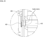
- FIG. 8 is a view showing a state in which a connecting cable according to an embodiment of the present disclosure is installed on a busbar frame.
- FIG. 9 is a view showing a state of the guide jig according to an embodiment of the present disclosure.
- the connecting cable 420 includes a first connecting cable 421 formed in a downward direction, a second connecting cable 422 that is bent and formed in one direction among the stacking directions of the battery cell 100 stack from the first connecting cable 421, and a third connecting cable 423 that is bent and formed in the other direction among the stacking directions of the battery cell 100 stack from the second connecting cable 422.
- the connecting cable 420 is formed in a flexible, flat shape, and may be bent and mounted around a flat surface.
- connection unit connector 430 is connected to a third connecting cable 423 and may be coupled to the connection unit 440 formed on one side of the busbar frame 300.
- connection unit 440 is formed on the opposite side of a second connecting cable 422 based on the first connecting cable 421, and the third connecting cable 423 is formed longer than the second connecting cable 422.
- the connecting cable 420 connected to the connection body 410 is first extended in the downward vertical direction through the first connecting cable 421 along the frame surface of the busbar frame 300, and reached the height at which the connection unit 440 is located, it is bent at 90 degrees through the second connecting cable 422 and horizontally extended in the opposite direction of the connection unit 440.
- the second connecting cable 422 may have a structure of being bent again in a 180-degree direction through the third connecting cable 423 to horizontally extend in a direction in which the connection unit 440 is located.
- the total length of the second connecting cable 422 and the third connecting cable 423 may be longer than the distance between the first connecting cable 421 and the connection unit 440. In this way, since the connecting cable 420 forms a curved part, and the second connecting cable 422 and the third connecting cable 423 secure an extra length, it is possible to stably operate the electrical connection route between the busbars when the connection unit 400 is tensioned.
- connection unit 400 When the connection unit 400 is coupled to the busbar frame, it can be coupled using a guide jig 450.
- the guide jig 450 When the connection unit 400 is coupled, the guide jig 450 is located at a predetermined position in the upper side part of the battery cell stack, and an opening 450a formed in the guide jig 450 may be formed into a size corresponding to the coupling position and shape of the connection unit 400.
- connection unit 400 when the connection unit 400 is coupled, the connection unit 400 may be inserted into the opening 450a of the guide jig 450 and coupled to the busbar frame 300.
- the coupling position of the connection unit 400 can be easily grasped, and precise and rapid coupling of the connection unit 400 may be performed.
- the battery module described above may be included in the battery pack.
- the battery pack may have a structure in which one or more battery modules according to the present embodiment are collected, and then packed by adding a battery management system (BMS) and a cooling device to manage the temperature or voltage of the battery.
- BMS battery management system
- the battery pack can be applied to various devices.
- a device may be applied to a vehicle such as an electric bicycle, an electric vehicle, or a hybrid vehicle, but the present disclosure is not limited thereto, and is applicable to various devices that can use a battery module, which also belongs to the scope of the present disclosure.
Landscapes
- Chemical & Material Sciences (AREA)
- Chemical Kinetics & Catalysis (AREA)
- Electrochemistry (AREA)
- General Chemical & Material Sciences (AREA)
- Engineering & Computer Science (AREA)
- Manufacturing & Machinery (AREA)
- Microelectronics & Electronic Packaging (AREA)
- Aviation & Aerospace Engineering (AREA)
- Battery Mounting, Suspending (AREA)
- Connection Of Batteries Or Terminals (AREA)
Applications Claiming Priority (2)
| Application Number | Priority Date | Filing Date | Title |
|---|---|---|---|
| KR1020190072498A KR102503536B1 (ko) | 2019-06-18 | 2019-06-18 | 전지 모듈 및 이를 포함하는 전지팩 |
| PCT/KR2020/004904 WO2020256264A1 (ko) | 2019-06-18 | 2020-04-10 | 전지 모듈 및 이를 포함하는 전지팩 |
Publications (3)
| Publication Number | Publication Date |
|---|---|
| EP3772124A1 EP3772124A1 (en) | 2021-02-03 |
| EP3772124A4 EP3772124A4 (en) | 2021-06-23 |
| EP3772124B1 true EP3772124B1 (en) | 2025-07-02 |
Family
ID=74037494
Family Applications (1)
| Application Number | Title | Priority Date | Filing Date |
|---|---|---|---|
| EP20800539.7A Active EP3772124B1 (en) | 2019-06-18 | 2020-04-10 | Battery module and battery pack including the same |
Country Status (8)
| Country | Link |
|---|---|
| US (1) | US12176496B2 (ko) |
| EP (1) | EP3772124B1 (ko) |
| JP (1) | JP7062209B2 (ko) |
| KR (1) | KR102503536B1 (ko) |
| CN (1) | CN112470335B (ko) |
| ES (1) | ES3036792T3 (ko) |
| HU (1) | HUE072094T2 (ko) |
| WO (1) | WO2020256264A1 (ko) |
Families Citing this family (12)
| Publication number | Priority date | Publication date | Assignee | Title |
|---|---|---|---|---|
| KR102798546B1 (ko) * | 2019-10-18 | 2025-04-18 | 주식회사 엘지에너지솔루션 | 전지 모듈 |
| KR102792210B1 (ko) | 2019-12-05 | 2025-04-04 | 주식회사 엘지에너지솔루션 | 전지 모듈 및 이를 포함하는 전지 팩 |
| KR102937927B1 (ko) * | 2020-09-22 | 2026-03-10 | 주식회사 엘지에너지솔루션 | 전지 모듈 및 이를 포함하는 전지팩 |
| KR102945051B1 (ko) * | 2020-09-22 | 2026-03-26 | 주식회사 엘지에너지솔루션 | 전지 모듈 및 이를 포함하는 전지팩 |
| KR20220043379A (ko) | 2020-09-29 | 2022-04-05 | 에이치그린파워 주식회사 | 소형화 배터리 모듈 및 이를 갖는 배터리 팩 |
| KR102798589B1 (ko) * | 2021-01-14 | 2025-04-18 | 주식회사 엘지에너지솔루션 | 전지 모듈 및 이를 포함하는 전지 팩 |
| CN115189104B (zh) | 2021-04-06 | 2024-11-08 | 莫仕连接器(成都)有限公司 | 电池连接模组 |
| KR102894629B1 (ko) * | 2021-06-08 | 2025-12-03 | 주식회사 엘지에너지솔루션 | 연성 평판 케이블의 절곡된 형상을 유지하는 수단을 포함하는 배터리 모듈 |
| CN113948812B (zh) * | 2021-11-19 | 2025-03-07 | 东莞市硅翔绝缘材料有限公司 | 用于新能源汽车动力电池的采样fpc分层结构 |
| EP4510370B1 (en) * | 2022-05-23 | 2026-04-01 | LG Energy Solution, Ltd. | Battery module |
| CN121773523A (zh) * | 2023-09-08 | 2026-03-31 | 株式会社Lg新能源 | 电池模块 |
| CN119108773B (zh) * | 2024-11-08 | 2025-02-14 | 中创新航科技集团股份有限公司 | Ffc组件及电池包 |
Family Cites Families (23)
| Publication number | Priority date | Publication date | Assignee | Title |
|---|---|---|---|---|
| US7875378B2 (en) | 2006-03-06 | 2011-01-25 | Lg Chem, Ltd. | Voltage sensing member and battery module employed with the same |
| WO2007102670A1 (en) | 2006-03-06 | 2007-09-13 | Lg Chem, Ltd. | Middle or large-sized battery module |
| JP2011210710A (ja) * | 2010-03-12 | 2011-10-20 | Autonetworks Technologies Ltd | 電池モジュール |
| KR101201748B1 (ko) | 2010-11-05 | 2012-11-15 | 에스비리모티브 주식회사 | 전지 모듈 |
| KR101293952B1 (ko) * | 2010-11-23 | 2013-08-07 | 주식회사 엘지화학 | 신규한 구조의 버스 바 어셈블리 |
| KR101443833B1 (ko) * | 2012-03-26 | 2014-09-23 | 주식회사 엘지화학 | 신규한 구조의 외부 입출력 케이블 어셈블리 및 이를 포함하는 전지모듈 어셈블리 |
| JP5896813B2 (ja) * | 2012-04-05 | 2016-03-30 | 矢崎総業株式会社 | 電源装置 |
| KR20140072689A (ko) | 2012-12-05 | 2014-06-13 | 에스케이이노베이션 주식회사 | 전지모듈 어셈블리 |
| KR102003067B1 (ko) | 2012-12-21 | 2019-07-24 | 타이코에이엠피 주식회사 | 전압 센싱 모듈 및 이를 구비하는 전지모듈 |
| KR102258973B1 (ko) * | 2013-10-31 | 2021-06-02 | 타이코에이엠피 주식회사 | 센싱 블록 및 이를 포함하는 배터리 패키지 |
| US10573938B2 (en) * | 2015-06-25 | 2020-02-25 | Te Connectivity Corporation | Battery module with a temperature monitoring assembly |
| KR102089645B1 (ko) * | 2016-02-12 | 2020-03-17 | 주식회사 엘지화학 | 배터리 모듈, 이러한 배터리 모듈을 포함하는 배터리 팩 및 이러한 배터리 팩을 포함하는 자동차 |
| WO2017204084A1 (ja) * | 2016-05-23 | 2017-11-30 | 古河電気工業株式会社 | フレキシブルフラットケーブル接続具、フレキシブルフラットケーブル接続構造体及び回転コネクタ装置 |
| KR102059612B1 (ko) | 2016-08-24 | 2019-12-26 | 주식회사 엘지화학 | 전지모듈 내에서 공간을 적게 점유하는 상호 연결 부재 및 이를 포함하는 전지모듈 |
| KR102102927B1 (ko) | 2016-10-06 | 2020-04-21 | 주식회사 엘지화학 | 배터리 모듈, 이러한 배터리 모듈을 포함하는 배터리 팩 및 이러한 배터리 팩을 포함하는 자동차 |
| KR102033001B1 (ko) * | 2017-02-28 | 2019-10-16 | 주식회사 유라코퍼레이션 | 프레임 조립체, 프레임 조립체의 제조 방법 및 배터리 모듈의 제조 방법 |
| RS61814B1 (sr) | 2016-12-27 | 2021-06-30 | Yura Corporation Co Ltd | Fleksibilna strujna ploča i okvir koji uključuje istu |
| CN110114904B (zh) | 2016-12-27 | 2022-07-15 | 裕罗有限公司 | 汇流排组件及支架组件 |
| KR102087699B1 (ko) * | 2017-11-27 | 2020-04-28 | 주식회사 유라코퍼레이션 | 연성회로기판 및 이를 이용하는 배터리팩 |
| KR101829350B1 (ko) * | 2016-12-30 | 2018-02-14 | 한국단자공업 주식회사 | 배터리모듈용 센싱장치 |
| WO2018159928A1 (ko) * | 2017-02-28 | 2018-09-07 | 주식회사 유라코퍼레이션 | 프레임 조립체 및 이를 제조하기 위한 방법 |
| US10601003B2 (en) * | 2017-10-30 | 2020-03-24 | Lg Chem, Ltd. | Battery module and method of assembling the battery module |
| KR101944111B1 (ko) | 2018-04-24 | 2019-01-30 | 주식회사 경신 | 차량용 배터리 셀의 전압 측정장치 |
-
2019
- 2019-06-18 KR KR1020190072498A patent/KR102503536B1/ko active Active
-
2020
- 2020-04-10 JP JP2020565821A patent/JP7062209B2/ja active Active
- 2020-04-10 ES ES20800539T patent/ES3036792T3/es active Active
- 2020-04-10 WO PCT/KR2020/004904 patent/WO2020256264A1/ko not_active Ceased
- 2020-04-10 EP EP20800539.7A patent/EP3772124B1/en active Active
- 2020-04-10 US US17/252,112 patent/US12176496B2/en active Active
- 2020-04-10 HU HUE20800539A patent/HUE072094T2/hu unknown
- 2020-04-10 CN CN202080002947.XA patent/CN112470335B/zh active Active
Also Published As
| Publication number | Publication date |
|---|---|
| US20210273267A1 (en) | 2021-09-02 |
| US12176496B2 (en) | 2024-12-24 |
| WO2020256264A1 (ko) | 2020-12-24 |
| ES3036792T3 (en) | 2025-09-24 |
| HUE072094T2 (hu) | 2025-10-28 |
| CN112470335A (zh) | 2021-03-09 |
| EP3772124A4 (en) | 2021-06-23 |
| EP3772124A1 (en) | 2021-02-03 |
| KR102503536B1 (ko) | 2023-02-23 |
| KR20200144422A (ko) | 2020-12-29 |
| JP2021531615A (ja) | 2021-11-18 |
| JP7062209B2 (ja) | 2022-05-06 |
| CN112470335B (zh) | 2023-04-28 |
Similar Documents
| Publication | Publication Date | Title |
|---|---|---|
| EP3772124B1 (en) | Battery module and battery pack including the same | |
| US12166240B2 (en) | Battery module and battery pack including the same | |
| EP3828983B1 (en) | Battery module with icb assembly in a space-saving structure | |
| US12334600B2 (en) | Battery module and battery pack including same | |
| US12548805B2 (en) | Battery module, manufacturing method thereof and battery pack | |
| KR20210000260A (ko) | 커버 구조물을 포함하는 배터리 팩 및 전자 디바이스 및 자동차 | |
| EP3780155A1 (en) | Battery module and manufacturing method therefor | |
| EP4203150B1 (en) | Battery module and battery pack comprising the same | |
| US20220416327A1 (en) | Battery module and battery pack including the same | |
| EP4099490B1 (en) | Battery module and battery pack including the same | |
| KR20220041429A (ko) | 전지 모듈 및 이를 포함하는 전지팩 | |
| KR102809001B1 (ko) | 전지 모듈 및 이를 포함하는 전지 팩 | |
| KR102877572B1 (ko) | 전지 모듈 및 이를 포함하는 전지팩 | |
| US12476329B2 (en) | Battery module and battery pack including the same | |
| EP4636935A2 (en) | Logical cell, secondary battery module and secondary battery pack including the same | |
| KR102941252B1 (ko) | 전지팩 및 이를 포함하는 디바이스 | |
| KR20230097897A (ko) | 로지컬 셀, 이차전지 모듈 및 이를 포함하는 이차전지 팩 | |
| EP4060800A1 (en) | Battery module and battery pack including same |
Legal Events
| Date | Code | Title | Description |
|---|---|---|---|
| STAA | Information on the status of an ep patent application or granted ep patent |
Free format text: STATUS: UNKNOWN |
|
| STAA | Information on the status of an ep patent application or granted ep patent |
Free format text: STATUS: THE INTERNATIONAL PUBLICATION HAS BEEN MADE |
|
| PUAI | Public reference made under article 153(3) epc to a published international application that has entered the european phase |
Free format text: ORIGINAL CODE: 0009012 |
|
| STAA | Information on the status of an ep patent application or granted ep patent |
Free format text: STATUS: REQUEST FOR EXAMINATION WAS MADE |
|
| 17P | Request for examination filed |
Effective date: 20201111 |
|
| AK | Designated contracting states |
Kind code of ref document: A1 Designated state(s): AL AT BE BG CH CY CZ DE DK EE ES FI FR GB GR HR HU IE IS IT LI LT LU LV MC MK MT NL NO PL PT RO RS SE SI SK SM TR |
|
| AX | Request for extension of the european patent |
Extension state: BA ME |
|
| A4 | Supplementary search report drawn up and despatched |
Effective date: 20210527 |
|
| RIC1 | Information provided on ipc code assigned before grant |
Ipc: H01M 10/48 20060101AFI20210520BHEP Ipc: H01M 10/42 20060101ALI20210520BHEP Ipc: H01M 50/244 20210101ALI20210520BHEP Ipc: H01M 50/503 20210101ALI20210520BHEP Ipc: H01M 50/507 20210101ALI20210520BHEP |
|
| STAA | Information on the status of an ep patent application or granted ep patent |
Free format text: STATUS: EXAMINATION IS IN PROGRESS |
|
| RAP1 | Party data changed (applicant data changed or rights of an application transferred) |
Owner name: LG ENERGY SOLUTION LTD. |
|
| 17Q | First examination report despatched |
Effective date: 20220104 |
|
| RAP3 | Party data changed (applicant data changed or rights of an application transferred) |
Owner name: LG ENERGY SOLUTION, LTD. |
|
| DAV | Request for validation of the european patent (deleted) | ||
| DAX | Request for extension of the european patent (deleted) | ||
| REG | Reference to a national code |
Ref legal event code: R079 Free format text: PREVIOUS MAIN CLASS: H01M0002200000 Ipc: H01M0050211000 Ref country code: DE Ref legal event code: R079 Ref document number: 602020053887 Country of ref document: DE Free format text: PREVIOUS MAIN CLASS: H01M0002200000 Ipc: H01M0050211000 |
|
| RIC1 | Information provided on ipc code assigned before grant |
Ipc: H01M 50/507 20210101ALI20250204BHEP Ipc: H01M 50/503 20210101ALI20250204BHEP Ipc: H01M 50/244 20210101ALI20250204BHEP Ipc: H01M 50/298 20210101ALI20250204BHEP Ipc: H01M 50/249 20210101ALI20250204BHEP Ipc: H01M 50/211 20210101AFI20250204BHEP |
|
| GRAP | Despatch of communication of intention to grant a patent |
Free format text: ORIGINAL CODE: EPIDOSNIGR1 |
|
| STAA | Information on the status of an ep patent application or granted ep patent |
Free format text: STATUS: GRANT OF PATENT IS INTENDED |
|
| GRAJ | Information related to disapproval of communication of intention to grant by the applicant or resumption of examination proceedings by the epo deleted |
Free format text: ORIGINAL CODE: EPIDOSDIGR1 |
|
| STAA | Information on the status of an ep patent application or granted ep patent |
Free format text: STATUS: EXAMINATION IS IN PROGRESS |
|
| INTG | Intention to grant announced |
Effective date: 20250324 |
|
| INTC | Intention to grant announced (deleted) | ||
| GRAP | Despatch of communication of intention to grant a patent |
Free format text: ORIGINAL CODE: EPIDOSNIGR1 |
|
| STAA | Information on the status of an ep patent application or granted ep patent |
Free format text: STATUS: GRANT OF PATENT IS INTENDED |
|
| GRAS | Grant fee paid |
Free format text: ORIGINAL CODE: EPIDOSNIGR3 |
|
| GRAA | (expected) grant |
Free format text: ORIGINAL CODE: 0009210 |
|
| STAA | Information on the status of an ep patent application or granted ep patent |
Free format text: STATUS: THE PATENT HAS BEEN GRANTED |
|
| INTG | Intention to grant announced |
Effective date: 20250508 |
|
| AK | Designated contracting states |
Kind code of ref document: B1 Designated state(s): AL AT BE BG CH CY CZ DE DK EE ES FI FR GB GR HR HU IE IS IT LI LT LU LV MC MK MT NL NO PL PT RO RS SE SI SK SM TR |
|
| REG | Reference to a national code |
Ref country code: GB Ref legal event code: FG4D |
|
| REG | Reference to a national code |
Ref country code: CH Ref legal event code: EP |
|
| P01 | Opt-out of the competence of the unified patent court (upc) registered |
Free format text: CASE NUMBER: APP_28884/2025 Effective date: 20250617 |
|
| REG | Reference to a national code |
Ref country code: DE Ref legal event code: R096 Ref document number: 602020053887 Country of ref document: DE |
|
| REG | Reference to a national code |
Ref country code: IE Ref legal event code: FG4D |
|
| REG | Reference to a national code |
Ref country code: ES Ref legal event code: FG2A Ref document number: 3036792 Country of ref document: ES Kind code of ref document: T3 Effective date: 20250924 |
|
| REG | Reference to a national code |
Ref country code: HU Ref legal event code: AG4A Ref document number: E072094 Country of ref document: HU |
|
| REG | Reference to a national code |
Ref country code: NL Ref legal event code: MP Effective date: 20250702 |
|
| PG25 | Lapsed in a contracting state [announced via postgrant information from national office to epo] |
Ref country code: PT Free format text: LAPSE BECAUSE OF FAILURE TO SUBMIT A TRANSLATION OF THE DESCRIPTION OR TO PAY THE FEE WITHIN THE PRESCRIBED TIME-LIMIT Effective date: 20251103 |
|
| PG25 | Lapsed in a contracting state [announced via postgrant information from national office to epo] |
Ref country code: NL Free format text: LAPSE BECAUSE OF FAILURE TO SUBMIT A TRANSLATION OF THE DESCRIPTION OR TO PAY THE FEE WITHIN THE PRESCRIBED TIME-LIMIT Effective date: 20250702 |
|
| REG | Reference to a national code |
Ref country code: AT Ref legal event code: MK05 Ref document number: 1810337 Country of ref document: AT Kind code of ref document: T Effective date: 20250702 |
|
| PG25 | Lapsed in a contracting state [announced via postgrant information from national office to epo] |
Ref country code: IS Free format text: LAPSE BECAUSE OF FAILURE TO SUBMIT A TRANSLATION OF THE DESCRIPTION OR TO PAY THE FEE WITHIN THE PRESCRIBED TIME-LIMIT Effective date: 20251102 |
|
| PG25 | Lapsed in a contracting state [announced via postgrant information from national office to epo] |
Ref country code: NO Free format text: LAPSE BECAUSE OF FAILURE TO SUBMIT A TRANSLATION OF THE DESCRIPTION OR TO PAY THE FEE WITHIN THE PRESCRIBED TIME-LIMIT Effective date: 20251002 |
|
| REG | Reference to a national code |
Ref country code: LT Ref legal event code: MG9D |
|
| PG25 | Lapsed in a contracting state [announced via postgrant information from national office to epo] |
Ref country code: AT Free format text: LAPSE BECAUSE OF FAILURE TO SUBMIT A TRANSLATION OF THE DESCRIPTION OR TO PAY THE FEE WITHIN THE PRESCRIBED TIME-LIMIT Effective date: 20250702 |
|
| PG25 | Lapsed in a contracting state [announced via postgrant information from national office to epo] |
Ref country code: FI Free format text: LAPSE BECAUSE OF FAILURE TO SUBMIT A TRANSLATION OF THE DESCRIPTION OR TO PAY THE FEE WITHIN THE PRESCRIBED TIME-LIMIT Effective date: 20250702 |
|
| PG25 | Lapsed in a contracting state [announced via postgrant information from national office to epo] |
Ref country code: HR Free format text: LAPSE BECAUSE OF FAILURE TO SUBMIT A TRANSLATION OF THE DESCRIPTION OR TO PAY THE FEE WITHIN THE PRESCRIBED TIME-LIMIT Effective date: 20250702 |
|
| PG25 | Lapsed in a contracting state [announced via postgrant information from national office to epo] |
Ref country code: GR Free format text: LAPSE BECAUSE OF FAILURE TO SUBMIT A TRANSLATION OF THE DESCRIPTION OR TO PAY THE FEE WITHIN THE PRESCRIBED TIME-LIMIT Effective date: 20251003 |
|
| PG25 | Lapsed in a contracting state [announced via postgrant information from national office to epo] |
Ref country code: CZ Free format text: LAPSE BECAUSE OF FAILURE TO SUBMIT A TRANSLATION OF THE DESCRIPTION OR TO PAY THE FEE WITHIN THE PRESCRIBED TIME-LIMIT Effective date: 20250702 Ref country code: SE Free format text: LAPSE BECAUSE OF FAILURE TO SUBMIT A TRANSLATION OF THE DESCRIPTION OR TO PAY THE FEE WITHIN THE PRESCRIBED TIME-LIMIT Effective date: 20250702 |
|
| PG25 | Lapsed in a contracting state [announced via postgrant information from national office to epo] |
Ref country code: LV Free format text: LAPSE BECAUSE OF FAILURE TO SUBMIT A TRANSLATION OF THE DESCRIPTION OR TO PAY THE FEE WITHIN THE PRESCRIBED TIME-LIMIT Effective date: 20250702 |
|
| PG25 | Lapsed in a contracting state [announced via postgrant information from national office to epo] |
Ref country code: BG Free format text: LAPSE BECAUSE OF FAILURE TO SUBMIT A TRANSLATION OF THE DESCRIPTION OR TO PAY THE FEE WITHIN THE PRESCRIBED TIME-LIMIT Effective date: 20250702 Ref country code: PL Free format text: LAPSE BECAUSE OF FAILURE TO SUBMIT A TRANSLATION OF THE DESCRIPTION OR TO PAY THE FEE WITHIN THE PRESCRIBED TIME-LIMIT Effective date: 20250702 |
|
| PG25 | Lapsed in a contracting state [announced via postgrant information from national office to epo] |
Ref country code: RS Free format text: LAPSE BECAUSE OF FAILURE TO SUBMIT A TRANSLATION OF THE DESCRIPTION OR TO PAY THE FEE WITHIN THE PRESCRIBED TIME-LIMIT Effective date: 20251002 |
|
| PG25 | Lapsed in a contracting state [announced via postgrant information from national office to epo] |
Ref country code: SM Free format text: LAPSE BECAUSE OF FAILURE TO SUBMIT A TRANSLATION OF THE DESCRIPTION OR TO PAY THE FEE WITHIN THE PRESCRIBED TIME-LIMIT Effective date: 20250702 |
|
| PGFP | Annual fee paid to national office [announced via postgrant information from national office to epo] |
Ref country code: GB Payment date: 20260324 Year of fee payment: 7 |
|
| PG25 | Lapsed in a contracting state [announced via postgrant information from national office to epo] |
Ref country code: DK Free format text: LAPSE BECAUSE OF FAILURE TO SUBMIT A TRANSLATION OF THE DESCRIPTION OR TO PAY THE FEE WITHIN THE PRESCRIBED TIME-LIMIT Effective date: 20250702 |
|
| PG25 | Lapsed in a contracting state [announced via postgrant information from national office to epo] |
Ref country code: IT Free format text: LAPSE BECAUSE OF FAILURE TO SUBMIT A TRANSLATION OF THE DESCRIPTION OR TO PAY THE FEE WITHIN THE PRESCRIBED TIME-LIMIT Effective date: 20250702 |
|
| PGFP | Annual fee paid to national office [announced via postgrant information from national office to epo] |
Ref country code: BE Payment date: 20260323 Year of fee payment: 7 |
|
| PGFP | Annual fee paid to national office [announced via postgrant information from national office to epo] |
Ref country code: FR Payment date: 20260323 Year of fee payment: 7 |
|
| PG25 | Lapsed in a contracting state [announced via postgrant information from national office to epo] |
Ref country code: SK Free format text: LAPSE BECAUSE OF FAILURE TO SUBMIT A TRANSLATION OF THE DESCRIPTION OR TO PAY THE FEE WITHIN THE PRESCRIBED TIME-LIMIT Effective date: 20250702 Ref country code: EE Free format text: LAPSE BECAUSE OF FAILURE TO SUBMIT A TRANSLATION OF THE DESCRIPTION OR TO PAY THE FEE WITHIN THE PRESCRIBED TIME-LIMIT Effective date: 20250702 |