EP3772076B1 - Vorrichtung zur tür- und phasentrennung in leistungsschaltern mit formgehäuse - Google Patents
Vorrichtung zur tür- und phasentrennung in leistungsschaltern mit formgehäuse Download PDFInfo
- Publication number
- EP3772076B1 EP3772076B1 EP19189753.7A EP19189753A EP3772076B1 EP 3772076 B1 EP3772076 B1 EP 3772076B1 EP 19189753 A EP19189753 A EP 19189753A EP 3772076 B1 EP3772076 B1 EP 3772076B1
- Authority
- EP
- European Patent Office
- Prior art keywords
- circuit breaker
- low voltage
- insulating
- voltage circuit
- conductive element
- Prior art date
- Legal status (The legal status is an assumption and is not a legal conclusion. Google has not performed a legal analysis and makes no representation as to the accuracy of the status listed.)
- Active
Links
Images


Classifications
-
- H—ELECTRICITY
- H01—ELECTRIC ELEMENTS
- H01H—ELECTRIC SWITCHES; RELAYS; SELECTORS; EMERGENCY PROTECTIVE DEVICES
- H01H71/00—Details of the protective switches or relays covered by groups H01H73/00 - H01H83/00
- H01H71/02—Housings; Casings; Bases; Mountings
-
- H—ELECTRICITY
- H01—ELECTRIC ELEMENTS
- H01H—ELECTRIC SWITCHES; RELAYS; SELECTORS; EMERGENCY PROTECTIVE DEVICES
- H01H9/00—Details of switching devices, not covered by groups H01H1/00 - H01H7/00
- H01H9/02—Bases, casings, or covers
- H01H9/0264—Protective covers for terminals
-
- H—ELECTRICITY
- H01—ELECTRIC ELEMENTS
- H01H—ELECTRIC SWITCHES; RELAYS; SELECTORS; EMERGENCY PROTECTIVE DEVICES
- H01H71/00—Details of the protective switches or relays covered by groups H01H73/00 - H01H83/00
- H01H71/10—Operating or release mechanisms
- H01H71/12—Automatic release mechanisms with or without manual release
- H01H71/123—Automatic release mechanisms with or without manual release using a solid-state trip unit
-
- H—ELECTRICITY
- H01—ELECTRIC ELEMENTS
- H01H—ELECTRIC SWITCHES; RELAYS; SELECTORS; EMERGENCY PROTECTIVE DEVICES
- H01H71/00—Details of the protective switches or relays covered by groups H01H73/00 - H01H83/00
- H01H71/74—Means for adjusting the conditions under which the device will function to provide protection
-
- H—ELECTRICITY
- H01—ELECTRIC ELEMENTS
- H01H—ELECTRIC SWITCHES; RELAYS; SELECTORS; EMERGENCY PROTECTIVE DEVICES
- H01H73/00—Protective overload circuit-breaking switches in which excess current opens the contacts by automatic release of mechanical energy stored by previous operation of a hand reset mechanism
- H01H73/02—Details
- H01H73/18—Means for extinguishing or suppressing arc
-
- H—ELECTRICITY
- H01—ELECTRIC ELEMENTS
- H01H—ELECTRIC SWITCHES; RELAYS; SELECTORS; EMERGENCY PROTECTIVE DEVICES
- H01H77/00—Protective overload circuit-breaking switches operated by excess current and requiring separate action for resetting
-
- H—ELECTRICITY
- H01—ELECTRIC ELEMENTS
- H01H—ELECTRIC SWITCHES; RELAYS; SELECTORS; EMERGENCY PROTECTIVE DEVICES
- H01H71/00—Details of the protective switches or relays covered by groups H01H73/00 - H01H83/00
- H01H2071/006—Provisions for user interfaces for electrical protection devices
-
- H—ELECTRICITY
- H01—ELECTRIC ELEMENTS
- H01H—ELECTRIC SWITCHES; RELAYS; SELECTORS; EMERGENCY PROTECTIVE DEVICES
- H01H71/00—Details of the protective switches or relays covered by groups H01H73/00 - H01H83/00
- H01H71/02—Housings; Casings; Bases; Mountings
- H01H71/025—Constructional details of housings or casings not concerning the mounting or assembly of the different internal parts
-
- H—ELECTRICITY
- H01—ELECTRIC ELEMENTS
- H01H—ELECTRIC SWITCHES; RELAYS; SELECTORS; EMERGENCY PROTECTIVE DEVICES
- H01H71/00—Details of the protective switches or relays covered by groups H01H73/00 - H01H83/00
- H01H71/08—Terminals; Connections
-
- H—ELECTRICITY
- H01—ELECTRIC ELEMENTS
- H01H—ELECTRIC SWITCHES; RELAYS; SELECTORS; EMERGENCY PROTECTIVE DEVICES
- H01H9/00—Details of switching devices, not covered by groups H01H1/00 - H01H7/00
- H01H9/0072—Details of switching devices, not covered by groups H01H1/00 - H01H7/00 particular to three-phase switches
-
- H—ELECTRICITY
- H01—ELECTRIC ELEMENTS
- H01H—ELECTRIC SWITCHES; RELAYS; SELECTORS; EMERGENCY PROTECTIVE DEVICES
- H01H9/00—Details of switching devices, not covered by groups H01H1/00 - H01H7/00
- H01H9/30—Means for extinguishing or preventing arc between current-carrying parts
- H01H9/34—Stationary parts for restricting or subdividing the arc, e.g. barrier plate
- H01H9/342—Venting arrangements for arc chutes
Definitions
- the present invention relates to a device for door and phase segregation in low voltage circuit breakers, in particular in molded case circuit breakers.
- switching devices such as for example circuit breakers, disconnectors, contactors, limiters, hereinafter referred to as switches, for reasons of brevity, generally comprise a casing and a plurality of electrical poles, associated to each of which there is at least one pair of contacts that can be coupled to and uncoupled from one another.
- Switches of the known art also comprise control means that cause relative movement of said pairs of contacts so that they can assume at least one first, coupling, position (circuit closed) and one second, separation, position (circuit open).
- the critical function of interrupting the current is provided in a specific portion of the circuit breaker which is constituted by the so-called deionizing arc chamber.
- Arc chambers can be simple regions provided in the casing of the switch, or else can comprise various modular elements shaped, for example, like casings made of insulating material equipped with arc-breaking plates.
- Modular arc chambers which are more advanced, present the advantage of being easily replaceable; moreover they can also be manufactured using materials that are more suitable as compared, for example, to the ones used for the casing of the switch.
- the voltage between the contacts causes the dielectric discharge of the air, leading to the formation of the electric arc in the chamber.
- the arc is propelled by electromagnetic and fluid-dynamics effects inside a series of arc-breaking metal plates arranged in the chamber, which are meant to extinguish said arc by cooling and splitting actions.
- the energy released by Joule effect is very high and causes thermal and mechanical stresses inside the plate containment region. It is worth noting that, depending on the kind of switch and the arching phenomenon that takes place, the pressure in the contact zone, and in particular in the arc chamber, can reach very high values, e.g. as high as 30-40 bars, while the temperature of the ionized gases can reach values of 3000-4000 °K.
- the arc chamber is provided with an adequate system for venting off and cooling the hot gases that develop during arching.
- the existing arc chambers for low voltage switching devices are generally provided with openings for the discharge of the hot gases produced during arching and with a filtering system which, among others, has the functions of cooling the gas, reducing the velocity of the flow at the discharge, preventing the emission of flame and/or incandescent gases.
- Document US2008/074217 discloses a low voltage circuit breaker, having a plurality of phases each provided with a lug for electrical connection of said circuit breaker, a venting aperture for venting off gases, and a device for door and phase segregation comprising a conductive element fixed to a corresponding lug of said circuit breaker and provided with electrical connection means for electrical connection of said circuit breaker, whereby said device comprises an insulating element interposed between two adjacent phases of said circuit breaker.
- the main aim of the present invention is to provide a low voltage circuit breaker, in particular a molded case circuit breaker, provided with a system that allows solving or at least reducing the above-mentioned problems.
- Still another object of the present invention is to provide a device able to guarantee an effective door and phase segregation in low voltage circuit breakers, in particular in molded case circuit breakers, that can be easily manufactured at industrial level, at competitive costs with respect to the solutions of the state of the art.
- a low voltage circuit breaker in particular a molded case circuit breaker, provided with a reliable door and phase segregation device is also an object of the present invention.
- the present invention provides a device for door and phase segregation in low voltage circuit breakers, in particular in molded case circuit breakers, having a plurality of phases each provided with a lug for electrical connection of said circuit breaker and a venting aperture for venting off gases;
- the device of the invention comprises a conductive element adapted to be fixed to a corresponding lug of said circuit breaker and provided with electrical connection means for electrical connection of said circuit breaker.
- the device for door and phase segregation of the present invention is characterized in that it comprises a first insulating element covering said conductive element and a second insulating element adapted to be interposed between two adjacent phases of said circuit breaker
- the first and the second insulating elements are able to create an effective segregation between the various phases and between each phase and the front door of the panel, thereby solving, or at least greatly reducing, the problems of the prior art systems.
- the conductive element is substantially L-shaped.
- the first insulating element comprises a first insulating body which is also substantially L-shaped and which is fitted onto said conductive element.
- the first insulating element has a first and a second lateral surface which are substantially continuous and substantially L-shaped, and a top surface which is conveniently provided with an opening for accessing the connection means of said conductive element.
- said first insulating body has a rear and a bottom surface which are also provided with openings allowing the passage of said conductive element, so that the first insulating body can be slidingly inserted onto said conductive element and covers it completely on the front and lateral sides, thereby creating an effective insulation of said conductive element.
- the conductive element is provided with first fixing means for the mechanical connection to a corresponding lug of said circuit breaker; the conductive element can be also provided with second fixing means for mechanical connection of said electrical connection means.
- the first insulating body can be advantageously shaped with a front surface having a first portion and a second portion raised with respect to said first portion.
- One or more openings can be advantageously positioned on said first and/or second portion for accessing said first and/or second fixing means, thereby making very easy the installation of the device on the circuit breaker and the connection of this latter to the electrical circuit into which it is positioned.
- said first and second fixing means can be screw means adapted to effectively fix the conductive element to the terminals of the circuit breaker and to conductors (e.g., cables or bars) of the electrical circuit.
- said first insulating body is conveniently provided with an elongated protrusion substantially perpendicular to said first and second lateral surface and vertically extending along at least a portion of said first and second lateral surface.
- the elongated protrusion form a sort of screen, thereby channeling them away from the more sensitive parts of the circuit breaker.
- the first insulating body can be advantageously provided with a tab which is adapted to rest on a surface of said circuit breaker proximate to a venting aperture of said circuit breaker, on a front side thereof. In this way the hot ionized gases can be prevented to flow toward the front door of the panel into which the circuit breaker is inserted.
- said tab can be conveniently positioned in an intermediate position between said first and second portions of the front surface of the first insulating body .
- said second insulating element advantageously comprises an insulating fin vertically extending between two adjacent phases of said circuit breaker.
- said insulating fin is shaped so as to have a third and a fourth substantially continuous lateral surfaces and is conveniently provided with a third and a fourth lateral protrusions which are substantially perpendicular to said third and fourth lateral surfaces and which run vertically along at least a portion of said third and fourth lateral surfaces.
- the main body of the insulating fin provides an effective segregation between the various phases, while the third and fourth lateral protrusions provide an effective contribution to the segregation between the each phase and the front door of the panel.
- said third and fourth lateral protrusions of the insulating fin are adapted to rest on a surface of said circuit breaker proximate to a venting aperture of said circuit breaker, thereby providing an effective screen for the hot ionized gases coming from the arc chamber.
- a low voltage circuit breaker in particular a molded case circuit breaker comprising a device for door and phase segregation as disclosed herein is also part of the present invention.
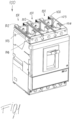
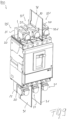
- the device for door and phase segregation is adapted to be used in low voltage circuit breakers, in particular in a molded case circuit breaker 100 as represented in figure 1 .
- the circuit breaker 100 has a plurality of phases 101, in the present case three phases, and associated to each of which there is at least a pair of contacts that can be coupled to and uncoupled from one another, thereby achieving a closed or open configuration.
- the circuit breaker also comprises control means that cause relative movement of said pairs of contacts so that they can assume a first, coupling, position (circuit closed) and a second, separation, position (circuit open).
- the operating principles and functioning, as well as the related components and mechanisms, of the circuit breaker used in the present invention can be of the conventional type and will not be described in further details.
- Each phase 101 of the circuit breaker 100 is also provided with one terminal 102 for the electrical connection of the circuit breaker 100 to a corresponding electrical circuit.
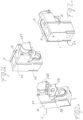
- the device for door and phase segregation of the present invention comprises a conductive element 1 which is adapted to be fixed to a corresponding lug or terminal 102 of each phase 101 of the circuit breaker 100.
- the conductive element 1 is normally provided with electrical connection means 11, 12 for electrical connection of said circuit breaker 100 to the corresponding electrical circuit.
- the electrical connection means are represented by the seats (holes) 11, 12, into which the terminal portion of, e.g. a connection cable or - more in general - a connection element, can be inserted.
- One of the distinguishing features of the device for door and phase segregation of the present invention is given by the fact that that it comprises a first insulating element 2 which covers said conductive element 1 and/or a second insulating element 3 which is adapted to be interposed between two adjacent phases 101 of said circuit breaker 100.
- the conductive element 1 is substantially L-shaped.
- the first insulating element 2 comprises a first insulating body 21 which is also substantially L-shaped so as to match the shape of the conductive element 1.
- the first insulating body 21 is fitted onto the conductive element 1 and has a first 22 and a second 23 lateral surfaces which are substantially continuous and substantially L-shaped; the first insulating body 21 has also a top surface 24 which is provided with an opening 25 for accessing the connection means 11, 12, e.g. the seats 11, 12 of connection cables, of the conductive element 1.
- the first insulating body 21 has a rear surface 26 and a bottom surface 27, which are provided with openings allowing the passage of said conductive element 1.
- the rear surface 26 of the first insulating body 21 is substantially completely open.
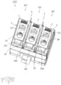
- the first insulating body 21 can be inserted over the conductive element 1 with a sliding action, thereby achieving the configuration of figures 2a-2c , and can be kept in place by small portions of the rear surface 26 and bottom surface 27.
- the conductive element 1 is conveniently provided with first fixing means 13 for mechanical connection to a corresponding lug/terminal 102 of the circuit breaker 100 and second fixing means 14 for the mechanical connection of said electrical connection means, e.g. the terminal portion of one or more connection cables.
- the first insulating body 21 has a front surface 28 which is shaped so as to match the shape of the conductive element 1.
- the front surface 28 has a first portion 281 and a second portion 282 which is raised with respect to said first portion 281, so as to follow the L-shape of the conductive element 1.
- One or more openings 283, 284 are conveniently positioned on the first portion 281 and/or on the second portion 282 of the front surface 28 for accessing the first 13 and/or second 14 fixing means positioned on the conductive element 1.
- a third hole is positioned on the second portion 282 of the front surface 28 of the first insulating body 21, said third hole being closed by a cover 285 in the embodiment shown in the attached figure.
- the first 13 and second 14 fixing means can be screw means, that are easily accessible through the openings 283 and 284 (as well as through the opening closed by the cover 285) and can therefore be easily operated to fix the device to the circuit breaker 100 and to fix the cable terminals to the conductive element 1.
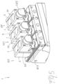
- the first insulating body 21 is provided on both sides thereof with an elongated protrusion 20 which is substantially perpendicular to the first 22 and second 23 lateral surface the first insulating body 21.
- the elongated protrusions 20 extend vertically along at least a portion of the first 22 and second 23 lateral surface of the first insulating body 21.
- the first 22 and second 23 lateral surface of the first insulating body 21 create a screen for the passage of the hot gases coming out from the venting aperture 103, 104 toward the rear portion of the circuit breaker 100.
- the first insulating body 21 can be conveniently provided with a tab 29 which is adapted to rest on a surface of said circuit breaker 100 proximate to a venting aperture 103, 104 of said circuit breaker 100.
- said tab 29 can be conveniently positioned in an intermediate position between said first 281 and second 282 portions of the front surface 28 of the first insulating body 21.
- the tab 29 of the first insulating body 21 creates a screen for the passage of the hot gases coming out from the venting aperture 103, 104 toward the front portion of the circuit breaker 100, thereby effectively segregating each phase 101 from the front door of the panel.
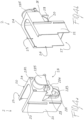
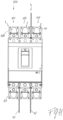
- the second insulating element 3 typically comprises an insulating fin 31 which extends vertically between two adjacent phases 101 of said circuit breaker 100.
- the insulating fin 31 is therefore able to effectively segregate the various phases 101 form each other.
- the insulating fin 31 can be easily inserted between the phases 101 with a simple sliding action.
- the base of the insulating fin 31 can be conveniently shaped so as to match the shape of a guide positioned on the circuit breaker 100 between the various phases 101.
- Other fixing or insertion means can however be used depending on the needs.
- said insulating fin 31 is shaped so as to have a third 33 and a fourth 34 substantially continuous lateral surfaces.
- the insulating fin 31 is provided on both sides thereof with a third 331 and a fourth 341 lateral protrusions which are substantially perpendicular to the third 33 and fourth 34 lateral surfaces of the insulating fin 31.
- the third 331 and a fourth 341 lateral protrusions run vertically along at least a portion of said third 33 and fourth 34 lateral surfaces of the insulating fin 31.
- said third 331 and fourth 341 lateral protrusions are adapted to rest on a surface of said circuit breaker 100 proximate to a venting aperture 103, 104 of said circuit breaker 100.
- Shape and dimensions of the third 331 and fourth 341 lateral protrusions can be any according to the needs.
- the third 331 and fourth 341 lateral protrusions of the insulating fin 31 creates a screen for the passage of the hot gases coming out from the venting aperture 103, 104 toward the front portion of the circuit breaker 100, thereby effectively segregating each phase 101 from the front door of the panel.
- the device for door and phase segregation in low voltage circuit breakers of the present invention allows solving the previously underlined technical problems. Indeed, it has been seen that a device for door and phase segregation according to the present invention, thanks to its structure, is able to effectively segregate the various phases among each other and also with respect to the front.
- an effective segregation can be carried out by using the first insulating element 2 alone, while, as shown in figure 7 and 8 , an effective segregation can be also carried out by using the second insulating element 3 alone.
Landscapes
- Patch Boards (AREA)
- Breakers (AREA)
- Switch Cases, Indication, And Locking (AREA)
Claims (12)
- Niederspannungsleistungsschalter (100), insbesondere Kompaktleistungsschalter, mit mehreren Phasen (101), jeweils versehen mit einem Kabelschuh (102) zur elektrischen Verbindung des Leistungsschalters, einer Entlüftungsöffnung (103, 104) zum Ablassen von Gasen und einer Vorrichtung zur Tür- und Phasentrennung, die ein leitfähiges Element (1) umfasst, das an einem entsprechenden Kabelschuh (102) des Leistungsschalters (100) befestigt ist und mit elektrischen Verbindungsmitteln (11, 12) zur elektrischen Verbindung des Leistungsschalters (100) versehen ist, wobei die Vorrichtung ein erstes Isolierelement (2), das das leitfähige Element (1) bedeckt, und ein zweites Isolierelement (3), das zwischen zwei benachbarten Phasen (101) des Leistungsschalters (100) angeordnet ist, umfasst.
- Niederspannungsleistungsschalter (100) nach Anspruch 1, dadurch gekennzeichnet, dass das leitfähige Element (1) im Wesentlichen L-förmig ist und das erste Isolierelement (2) einen im Wesentlichen L-förmigen ersten Isolierkörper (21) umfasst, der auf das leitfähige Element (1) aufgesetzt ist und eine erste (22) und eine zweite (23) laterale Oberfläche, die im Wesentlichen durchgehend und im Wesentlichen L-förmig sind, und eine obere Oberfläche (24), die mit einer Öffnung (25) zum Zugreifen auf die Verbindungsmittel (11, 12) des leitfähigen Elements (1) versehen ist, aufweist.
- Niederspannungsleistungsschalter (100) nach Anspruch 2, dadurch gekennzeichnet, dass der erste Isolierkörper (21) eine hintere (26) und eine untere (27) Oberfläche aufweist, die mit Öffnungen versehen sind, die das Hindurchführen des leitfähigen Elements (1) ermöglichen, wobei der erste Isolierkörper (21) gleitend auf das leitfähige Element (1) einführbar ist.
- Niederspannungsleistungsschalter (100) nach Anspruch 2 oder 3, dadurch gekennzeichnet, dass das leitfähige Element (1) mit ersten Befestigungsmitteln (13) zur mechanischen Verbindung mit einem entsprechenden Kabelschuh (102) des Leistungsschalters (100) und zweiten Befestigungsmitteln (14) zur mechanischen Verbindung der elektrischen Verbindungsmittel versehen ist, und dadurch, dass der erste Isolierkörper (21) eine vordere Oberfläche (28) mit einem ersten Abschnitt (281) und einem in Bezug auf den ersten Abschnitt (281) erhöhten zweiten Abschnitt (282) aufweist, wobei eine oder mehrere Öffnungen (283, 284) auf dem ersten Abschnitt (281) und/oder dem zweiten Abschnitt (282) positioniert sind, um auf die ersten (13) und/oder die zweiten (14) Befestigungsmittel zuzugreifen.
- Niederspannungsleistungsschalter (100) nach Anspruch 4, dadurch gekennzeichnet, dass die ersten (13) und zweiten (14) Befestigungsmittel Schraubmittel sind.
- Niederspannungsleistungsschalter (100) nach einem oder mehreren der Ansprüche 2 bis 5, dadurch gekennzeichnet, dass der erste Isolierkörper (21) mit einem länglichen Vorsprung (20) versehen ist, der im Wesentlichen senkrecht zu der ersten (22) und zweiten (23) lateralen Oberfläche ist und sich vertikal entlang mindestens eines Abschnitts der ersten (22) und zweiten (23) lateralen Oberfläche erstreckt.
- Niederspannungsleistungsschalter (100) nach einem oder mehreren der Ansprüche 2 bis 6, dadurch gekennzeichnet, dass der erste Isolierkörper (21) mit einer Lasche (29) versehen ist, die dazu ausgelegt ist, auf einer Oberfläche des Leistungsschalters (100) nahe einer Entlüftungsöffnung (103, 104) des Leistungsschalters (100) aufzuliegen.
- Niederspannungsleistungsschalter (100) nach den Ansprüchen 4 und 7, dadurch gekennzeichnet, dass die Lasche (29) in einer Zwischenposition zwischen dem ersten (281) und zweiten (282) Abschnitt der vorderen Oberfläche (28) positioniert ist.
- Niederspannungsleistungsschalter (100) nach einem oder mehreren der vorhergehenden Ansprüche, dadurch gekennzeichnet, dass das zweite Isolierelement (3) eine Isolierrippe (31) umfasst, die sich vertikal zwischen zwei benachbarten Phasen (101) des Leistungsschalters (100) erstreckt.
- Niederspannungsleistungsschalter (100) nach Anspruch 9, dadurch gekennzeichnet, dass die Isolierrippe (31) eine dritte (33) und eine vierte (34) im Wesentlichen durchgehende laterale Oberfläche aufweist und mit einem dritten (331) und einem vierten (341) lateralen Vorsprung versehen ist, die im Wesentlichen senkrecht zu der dritten (33) und vierten (34) lateralen Oberfläche sind und sich vertikal entlang mindestens eines Abschnitts der dritten (33) und vierten (34) lateralen Oberfläche erstrecken.
- Niederspannungsleistungsschalter (100) nach Anspruch 10, dadurch gekennzeichnet, dass der dritte (331) und vierte (341) laterale Vorsprung dazu ausgelegt sind, auf einer Oberfläche des Leistungsschalters (100) nahe einer Entlüftungsöffnung (103, 104) des Leistungsschalters (100) aufzuliegen.
- Niederspannungsleistungsschalter (100) nach einem oder mehreren der vorhergehenden Ansprüche, dadurch gekennzeichnet, dass es sich um einen Kompaktleistungsschalter handelt.
Priority Applications (3)
| Application Number | Priority Date | Filing Date | Title |
|---|---|---|---|
| EP19189753.7A EP3772076B1 (de) | 2019-08-02 | 2019-08-02 | Vorrichtung zur tür- und phasentrennung in leistungsschaltern mit formgehäuse |
| CN202010722837.2A CN112309783B (zh) | 2019-08-02 | 2020-07-24 | 塑壳断路器中的门相分离装置 |
| US16/983,021 US12237131B2 (en) | 2019-08-02 | 2020-08-03 | Device for door and phase segregation in molded case circuit breakers |
Applications Claiming Priority (1)
| Application Number | Priority Date | Filing Date | Title |
|---|---|---|---|
| EP19189753.7A EP3772076B1 (de) | 2019-08-02 | 2019-08-02 | Vorrichtung zur tür- und phasentrennung in leistungsschaltern mit formgehäuse |
Publications (2)
| Publication Number | Publication Date |
|---|---|
| EP3772076A1 EP3772076A1 (de) | 2021-02-03 |
| EP3772076B1 true EP3772076B1 (de) | 2025-01-22 |
Family
ID=67539340
Family Applications (1)
| Application Number | Title | Priority Date | Filing Date |
|---|---|---|---|
| EP19189753.7A Active EP3772076B1 (de) | 2019-08-02 | 2019-08-02 | Vorrichtung zur tür- und phasentrennung in leistungsschaltern mit formgehäuse |
Country Status (3)
| Country | Link |
|---|---|
| US (1) | US12237131B2 (de) |
| EP (1) | EP3772076B1 (de) |
| CN (1) | CN112309783B (de) |
Families Citing this family (2)
| Publication number | Priority date | Publication date | Assignee | Title |
|---|---|---|---|---|
| USD1031672S1 (en) * | 2019-07-11 | 2024-06-18 | Abb S.P.A. | Circuit breaker |
| CN220382010U (zh) * | 2023-07-19 | 2024-01-23 | 施耐德电气工业公司 | 接触器 |
Citations (2)
| Publication number | Priority date | Publication date | Assignee | Title |
|---|---|---|---|---|
| US6407354B1 (en) * | 2001-04-23 | 2002-06-18 | Eaton Corporation | Electrical switching apparatus including a baffle member having a deflectable flap |
| US20080074217A1 (en) * | 2006-09-25 | 2008-03-27 | Rockwell Automation Technologies, Inc. | Gas diverter for an electrical switching device |
Family Cites Families (10)
| Publication number | Priority date | Publication date | Assignee | Title |
|---|---|---|---|---|
| US4620076A (en) * | 1985-03-27 | 1986-10-28 | Westinghouse Electric Corp. | Circuit breaker apparatus with line terminal shields |
| FR2720195B1 (fr) * | 1994-05-18 | 1996-08-02 | Legrand Sa | Appareil électrique modulaire à bornes de raccordement protégées par une plaquette isolante. |
| US6172586B1 (en) * | 1999-11-05 | 2001-01-09 | Siemens Energy & Automation Inc. | Terminal barrier system for molded case circuit breaker |
| JP4360013B2 (ja) * | 2000-06-27 | 2009-11-11 | 三菱電機株式会社 | 回路遮断器 |
| US6624375B2 (en) * | 2001-04-04 | 2003-09-23 | Siemens Energy & Automation, Inc. | Wire lug/arc vent barrier molded case circuit breaker |
| ITBG20050023A1 (it) * | 2005-05-13 | 2006-11-14 | Abb Service Srl | Dispositivo di connessione per interruttori di bassa tensione |
| JP2008204863A (ja) * | 2007-02-21 | 2008-09-04 | Fuji Electric Fa Components & Systems Co Ltd | 電気機器の箱形端子装置 |
| IT1391125B1 (it) * | 2008-10-15 | 2011-11-18 | Abb Spa | Interruttore di bassa tensione. |
| IN2014KN00816A (de) * | 2011-12-12 | 2015-10-02 | Eaton Corp | |
| FR3040238B1 (fr) * | 2015-08-18 | 2019-01-25 | Schneider Electric Industries Sas | Disjoncteur electrique |
-
2019
- 2019-08-02 EP EP19189753.7A patent/EP3772076B1/de active Active
-
2020
- 2020-07-24 CN CN202010722837.2A patent/CN112309783B/zh active Active
- 2020-08-03 US US16/983,021 patent/US12237131B2/en active Active
Patent Citations (2)
| Publication number | Priority date | Publication date | Assignee | Title |
|---|---|---|---|---|
| US6407354B1 (en) * | 2001-04-23 | 2002-06-18 | Eaton Corporation | Electrical switching apparatus including a baffle member having a deflectable flap |
| US20080074217A1 (en) * | 2006-09-25 | 2008-03-27 | Rockwell Automation Technologies, Inc. | Gas diverter for an electrical switching device |
Also Published As
| Publication number | Publication date |
|---|---|
| CN112309783A (zh) | 2021-02-02 |
| US12237131B2 (en) | 2025-02-25 |
| EP3772076A1 (de) | 2021-02-03 |
| US20210035762A1 (en) | 2021-02-04 |
| CN112309783B (zh) | 2024-07-26 |
Similar Documents
| Publication | Publication Date | Title |
|---|---|---|
| EP3048625B1 (de) | Niederspannungsschaltpol | |
| EP2064718B1 (de) | Begasungsisolierung und lichtbogenkammeranordnung sowie elektrische schaltung damit | |
| CN101436474B (zh) | 电气开关设备、电弧罩组件及其烟囱 | |
| US20170098521A1 (en) | Breaker facilitating rapid movement and elongation of arc | |
| EP2393095B1 (de) | Schutzschalter mit Formgehäuse | |
| US20150270075A1 (en) | Modular gas exhaust assembly for a circuit breaker | |
| US12237131B2 (en) | Device for door and phase segregation in molded case circuit breakers | |
| CN114551131A (zh) | 直流电灭弧装置和电机式直流电开关设备 | |
| JP2012138173A (ja) | 回路遮断器 | |
| US11302502B2 (en) | Terminal clamp cover device for low voltage circuit breakers | |
| US11355290B2 (en) | Low voltage switch pole | |
| US2632826A (en) | Arc quenching circuit interrupter | |
| KR102788607B1 (ko) | 터미널 쇼트 방지를 위한 절연지를 구비한 기중 차단기 | |
| KR20150089729A (ko) | 배선용차단기의 아크소호장치 | |
| US12087525B2 (en) | Low voltage switch pole | |
| KR200490680Y1 (ko) | 배선용 차단기의 소호장치 | |
| US12362113B2 (en) | Low voltage switch pole | |
| US12444557B2 (en) | Low voltage switch pole | |
| EP4415014A1 (de) | Niederspannungsschaltpol | |
| US20240312734A1 (en) | Switch disconnector with an arc extinguishing shield plate | |
| JP7771736B2 (ja) | 回路遮断器 | |
| GB2587467A (en) | Terminal clamp cover device for low voltage circuit breakers | |
| WO2017141197A1 (en) | Electrical switch incorporating an arc splitter arrangement | |
| KR100926646B1 (ko) | 분전반용 과전류 차단기 |
Legal Events
| Date | Code | Title | Description |
|---|---|---|---|
| PUAI | Public reference made under article 153(3) epc to a published international application that has entered the european phase |
Free format text: ORIGINAL CODE: 0009012 |
|
| STAA | Information on the status of an ep patent application or granted ep patent |
Free format text: STATUS: THE APPLICATION HAS BEEN PUBLISHED |
|
| AK | Designated contracting states |
Kind code of ref document: A1 Designated state(s): AL AT BE BG CH CY CZ DE DK EE ES FI FR GB GR HR HU IE IS IT LI LT LU LV MC MK MT NL NO PL PT RO RS SE SI SK SM TR |
|
| AX | Request for extension of the european patent |
Extension state: BA ME |
|
| STAA | Information on the status of an ep patent application or granted ep patent |
Free format text: STATUS: REQUEST FOR EXAMINATION WAS MADE |
|
| 17P | Request for examination filed |
Effective date: 20210803 |
|
| RBV | Designated contracting states (corrected) |
Designated state(s): AL AT BE BG CH CY CZ DE DK EE ES FI FR GB GR HR HU IE IS IT LI LT LU LV MC MK MT NL NO PL PT RO RS SE SI SK SM TR |
|
| STAA | Information on the status of an ep patent application or granted ep patent |
Free format text: STATUS: EXAMINATION IS IN PROGRESS |
|
| 17Q | First examination report despatched |
Effective date: 20220504 |
|
| GRAP | Despatch of communication of intention to grant a patent |
Free format text: ORIGINAL CODE: EPIDOSNIGR1 |
|
| STAA | Information on the status of an ep patent application or granted ep patent |
Free format text: STATUS: GRANT OF PATENT IS INTENDED |
|
| INTG | Intention to grant announced |
Effective date: 20240913 |
|
| GRAS | Grant fee paid |
Free format text: ORIGINAL CODE: EPIDOSNIGR3 |
|
| GRAA | (expected) grant |
Free format text: ORIGINAL CODE: 0009210 |
|
| STAA | Information on the status of an ep patent application or granted ep patent |
Free format text: STATUS: THE PATENT HAS BEEN GRANTED |
|
| AK | Designated contracting states |
Kind code of ref document: B1 Designated state(s): AL AT BE BG CH CY CZ DE DK EE ES FI FR GB GR HR HU IE IS IT LI LT LU LV MC MK MT NL NO PL PT RO RS SE SI SK SM TR |
|
| REG | Reference to a national code |
Ref country code: GB Ref legal event code: FG4D |
|
| REG | Reference to a national code |
Ref country code: CH Ref legal event code: EP |
|
| REG | Reference to a national code |
Ref country code: IE Ref legal event code: FG4D |
|
| REG | Reference to a national code |
Ref country code: DE Ref legal event code: R096 Ref document number: 602019065031 Country of ref document: DE |
|
| REG | Reference to a national code |
Ref country code: NL Ref legal event code: MP Effective date: 20250122 |
|
| PG25 | Lapsed in a contracting state [announced via postgrant information from national office to epo] |
Ref country code: NL Free format text: LAPSE BECAUSE OF FAILURE TO SUBMIT A TRANSLATION OF THE DESCRIPTION OR TO PAY THE FEE WITHIN THE PRESCRIBED TIME-LIMIT Effective date: 20250122 |
|
| PG25 | Lapsed in a contracting state [announced via postgrant information from national office to epo] |
Ref country code: RS Free format text: LAPSE BECAUSE OF FAILURE TO SUBMIT A TRANSLATION OF THE DESCRIPTION OR TO PAY THE FEE WITHIN THE PRESCRIBED TIME-LIMIT Effective date: 20250422 |
|
| PG25 | Lapsed in a contracting state [announced via postgrant information from national office to epo] |
Ref country code: FI Free format text: LAPSE BECAUSE OF FAILURE TO SUBMIT A TRANSLATION OF THE DESCRIPTION OR TO PAY THE FEE WITHIN THE PRESCRIBED TIME-LIMIT Effective date: 20250122 |
|
| PG25 | Lapsed in a contracting state [announced via postgrant information from national office to epo] |
Ref country code: PL Free format text: LAPSE BECAUSE OF FAILURE TO SUBMIT A TRANSLATION OF THE DESCRIPTION OR TO PAY THE FEE WITHIN THE PRESCRIBED TIME-LIMIT Effective date: 20250122 |
|
| PG25 | Lapsed in a contracting state [announced via postgrant information from national office to epo] |
Ref country code: ES Free format text: LAPSE BECAUSE OF FAILURE TO SUBMIT A TRANSLATION OF THE DESCRIPTION OR TO PAY THE FEE WITHIN THE PRESCRIBED TIME-LIMIT Effective date: 20250122 |
|
| REG | Reference to a national code |
Ref country code: LT Ref legal event code: MG9D |
|
| PG25 | Lapsed in a contracting state [announced via postgrant information from national office to epo] |
Ref country code: NO Free format text: LAPSE BECAUSE OF FAILURE TO SUBMIT A TRANSLATION OF THE DESCRIPTION OR TO PAY THE FEE WITHIN THE PRESCRIBED TIME-LIMIT Effective date: 20250422 Ref country code: IS Free format text: LAPSE BECAUSE OF FAILURE TO SUBMIT A TRANSLATION OF THE DESCRIPTION OR TO PAY THE FEE WITHIN THE PRESCRIBED TIME-LIMIT Effective date: 20250522 |
|
| REG | Reference to a national code |
Ref country code: AT Ref legal event code: MK05 Ref document number: 1762105 Country of ref document: AT Kind code of ref document: T Effective date: 20250122 |
|
| PG25 | Lapsed in a contracting state [announced via postgrant information from national office to epo] |
Ref country code: HR Free format text: LAPSE BECAUSE OF FAILURE TO SUBMIT A TRANSLATION OF THE DESCRIPTION OR TO PAY THE FEE WITHIN THE PRESCRIBED TIME-LIMIT Effective date: 20250122 |
|
| PG25 | Lapsed in a contracting state [announced via postgrant information from national office to epo] |
Ref country code: PT Free format text: LAPSE BECAUSE OF FAILURE TO SUBMIT A TRANSLATION OF THE DESCRIPTION OR TO PAY THE FEE WITHIN THE PRESCRIBED TIME-LIMIT Effective date: 20250522 Ref country code: LV Free format text: LAPSE BECAUSE OF FAILURE TO SUBMIT A TRANSLATION OF THE DESCRIPTION OR TO PAY THE FEE WITHIN THE PRESCRIBED TIME-LIMIT Effective date: 20250122 |
|
| PG25 | Lapsed in a contracting state [announced via postgrant information from national office to epo] |
Ref country code: BG Free format text: LAPSE BECAUSE OF FAILURE TO SUBMIT A TRANSLATION OF THE DESCRIPTION OR TO PAY THE FEE WITHIN THE PRESCRIBED TIME-LIMIT Effective date: 20250122 Ref country code: GR Free format text: LAPSE BECAUSE OF FAILURE TO SUBMIT A TRANSLATION OF THE DESCRIPTION OR TO PAY THE FEE WITHIN THE PRESCRIBED TIME-LIMIT Effective date: 20250423 |
|
| PG25 | Lapsed in a contracting state [announced via postgrant information from national office to epo] |
Ref country code: AT Free format text: LAPSE BECAUSE OF FAILURE TO SUBMIT A TRANSLATION OF THE DESCRIPTION OR TO PAY THE FEE WITHIN THE PRESCRIBED TIME-LIMIT Effective date: 20250122 |
|
| PG25 | Lapsed in a contracting state [announced via postgrant information from national office to epo] |
Ref country code: SE Free format text: LAPSE BECAUSE OF FAILURE TO SUBMIT A TRANSLATION OF THE DESCRIPTION OR TO PAY THE FEE WITHIN THE PRESCRIBED TIME-LIMIT Effective date: 20250122 |
|
| PG25 | Lapsed in a contracting state [announced via postgrant information from national office to epo] |
Ref country code: SM Free format text: LAPSE BECAUSE OF FAILURE TO SUBMIT A TRANSLATION OF THE DESCRIPTION OR TO PAY THE FEE WITHIN THE PRESCRIBED TIME-LIMIT Effective date: 20250122 |
|
| PG25 | Lapsed in a contracting state [announced via postgrant information from national office to epo] |
Ref country code: DK Free format text: LAPSE BECAUSE OF FAILURE TO SUBMIT A TRANSLATION OF THE DESCRIPTION OR TO PAY THE FEE WITHIN THE PRESCRIBED TIME-LIMIT Effective date: 20250122 |
|
| PGFP | Annual fee paid to national office [announced via postgrant information from national office to epo] |
Ref country code: DE Payment date: 20250820 Year of fee payment: 7 |
|
| PGFP | Annual fee paid to national office [announced via postgrant information from national office to epo] |
Ref country code: IT Payment date: 20250825 Year of fee payment: 7 |
|
| PGFP | Annual fee paid to national office [announced via postgrant information from national office to epo] |
Ref country code: GB Payment date: 20250820 Year of fee payment: 7 |
|
| PGFP | Annual fee paid to national office [announced via postgrant information from national office to epo] |
Ref country code: FR Payment date: 20250828 Year of fee payment: 7 |
|
| PG25 | Lapsed in a contracting state [announced via postgrant information from national office to epo] |
Ref country code: CZ Free format text: LAPSE BECAUSE OF FAILURE TO SUBMIT A TRANSLATION OF THE DESCRIPTION OR TO PAY THE FEE WITHIN THE PRESCRIBED TIME-LIMIT Effective date: 20250122 Ref country code: EE Free format text: LAPSE BECAUSE OF FAILURE TO SUBMIT A TRANSLATION OF THE DESCRIPTION OR TO PAY THE FEE WITHIN THE PRESCRIBED TIME-LIMIT Effective date: 20250122 |
|
| REG | Reference to a national code |
Ref country code: DE Ref legal event code: R097 Ref document number: 602019065031 Country of ref document: DE |
|
| PG25 | Lapsed in a contracting state [announced via postgrant information from national office to epo] |
Ref country code: RO Free format text: LAPSE BECAUSE OF FAILURE TO SUBMIT A TRANSLATION OF THE DESCRIPTION OR TO PAY THE FEE WITHIN THE PRESCRIBED TIME-LIMIT Effective date: 20250122 |
|
| PG25 | Lapsed in a contracting state [announced via postgrant information from national office to epo] |
Ref country code: SK Free format text: LAPSE BECAUSE OF FAILURE TO SUBMIT A TRANSLATION OF THE DESCRIPTION OR TO PAY THE FEE WITHIN THE PRESCRIBED TIME-LIMIT Effective date: 20250122 |
|
| PLBE | No opposition filed within time limit |
Free format text: ORIGINAL CODE: 0009261 |
|
| STAA | Information on the status of an ep patent application or granted ep patent |
Free format text: STATUS: NO OPPOSITION FILED WITHIN TIME LIMIT |
|
| REG | Reference to a national code |
Ref country code: CH Ref legal event code: L10 Free format text: ST27 STATUS EVENT CODE: U-0-0-L10-L00 (AS PROVIDED BY THE NATIONAL OFFICE) Effective date: 20251203 |
|
| 26N | No opposition filed |
Effective date: 20251023 |
|
| REG | Reference to a national code |
Ref country code: CH Ref legal event code: H13 Free format text: ST27 STATUS EVENT CODE: U-0-0-H10-H13 (AS PROVIDED BY THE NATIONAL OFFICE) Effective date: 20260324 |