EP3771602B1 - Verbesserte hydraulische bremsanordnung für ein geländefahrzeug - Google Patents
Verbesserte hydraulische bremsanordnung für ein geländefahrzeug Download PDFInfo
- Publication number
- EP3771602B1 EP3771602B1 EP20188504.3A EP20188504A EP3771602B1 EP 3771602 B1 EP3771602 B1 EP 3771602B1 EP 20188504 A EP20188504 A EP 20188504A EP 3771602 B1 EP3771602 B1 EP 3771602B1
- Authority
- EP
- European Patent Office
- Prior art keywords
- valve
- hydraulic
- fluid
- brake arrangement
- valves
- Prior art date
- Legal status (The legal status is an assumption and is not a legal conclusion. Google has not performed a legal analysis and makes no representation as to the accuracy of the status listed.)
- Active
Links
Images
Classifications
-
- B—PERFORMING OPERATIONS; TRANSPORTING
- B60—VEHICLES IN GENERAL
- B60T—VEHICLE BRAKE CONTROL SYSTEMS OR PARTS THEREOF; BRAKE CONTROL SYSTEMS OR PARTS THEREOF, IN GENERAL; ARRANGEMENT OF BRAKING ELEMENTS ON VEHICLES IN GENERAL; PORTABLE DEVICES FOR PREVENTING UNWANTED MOVEMENT OF VEHICLES; VEHICLE MODIFICATIONS TO FACILITATE COOLING OF BRAKES
- B60T13/00—Transmitting braking action from initiating means to ultimate brake actuator with power assistance or drive; Brake systems incorporating such transmitting means, e.g. air-pressure brake systems
- B60T13/10—Transmitting braking action from initiating means to ultimate brake actuator with power assistance or drive; Brake systems incorporating such transmitting means, e.g. air-pressure brake systems with fluid assistance, drive, or release
- B60T13/66—Electrical control in fluid-pressure brake systems
- B60T13/662—Electrical control in fluid-pressure brake systems characterised by specified functions of the control system components
-
- B—PERFORMING OPERATIONS; TRANSPORTING
- B60—VEHICLES IN GENERAL
- B60T—VEHICLE BRAKE CONTROL SYSTEMS OR PARTS THEREOF; BRAKE CONTROL SYSTEMS OR PARTS THEREOF, IN GENERAL; ARRANGEMENT OF BRAKING ELEMENTS ON VEHICLES IN GENERAL; PORTABLE DEVICES FOR PREVENTING UNWANTED MOVEMENT OF VEHICLES; VEHICLE MODIFICATIONS TO FACILITATE COOLING OF BRAKES
- B60T11/00—Transmitting braking action from initiating means to ultimate brake actuator without power assistance or drive or where such assistance or drive is irrelevant
- B60T11/10—Transmitting braking action from initiating means to ultimate brake actuator without power assistance or drive or where such assistance or drive is irrelevant transmitting by fluid means, e.g. hydraulic
- B60T11/16—Master control, e.g. master cylinders
- B60T11/20—Tandem, side-by-side, or other multiple master cylinder units
- B60T11/21—Tandem, side-by-side, or other multiple master cylinder units with two pedals operating on respective circuits, pressures therein being equalised when both pedals are operated together, e.g. for steering
-
- B—PERFORMING OPERATIONS; TRANSPORTING
- B60—VEHICLES IN GENERAL
- B60T—VEHICLE BRAKE CONTROL SYSTEMS OR PARTS THEREOF; BRAKE CONTROL SYSTEMS OR PARTS THEREOF, IN GENERAL; ARRANGEMENT OF BRAKING ELEMENTS ON VEHICLES IN GENERAL; PORTABLE DEVICES FOR PREVENTING UNWANTED MOVEMENT OF VEHICLES; VEHICLE MODIFICATIONS TO FACILITATE COOLING OF BRAKES
- B60T13/00—Transmitting braking action from initiating means to ultimate brake actuator with power assistance or drive; Brake systems incorporating such transmitting means, e.g. air-pressure brake systems
- B60T13/10—Transmitting braking action from initiating means to ultimate brake actuator with power assistance or drive; Brake systems incorporating such transmitting means, e.g. air-pressure brake systems with fluid assistance, drive, or release
- B60T13/12—Transmitting braking action from initiating means to ultimate brake actuator with power assistance or drive; Brake systems incorporating such transmitting means, e.g. air-pressure brake systems with fluid assistance, drive, or release the fluid being liquid
- B60T13/14—Transmitting braking action from initiating means to ultimate brake actuator with power assistance or drive; Brake systems incorporating such transmitting means, e.g. air-pressure brake systems with fluid assistance, drive, or release the fluid being liquid using accumulators or reservoirs fed by pumps
- B60T13/142—Systems with master cylinder
-
- B—PERFORMING OPERATIONS; TRANSPORTING
- B60—VEHICLES IN GENERAL
- B60T—VEHICLE BRAKE CONTROL SYSTEMS OR PARTS THEREOF; BRAKE CONTROL SYSTEMS OR PARTS THEREOF, IN GENERAL; ARRANGEMENT OF BRAKING ELEMENTS ON VEHICLES IN GENERAL; PORTABLE DEVICES FOR PREVENTING UNWANTED MOVEMENT OF VEHICLES; VEHICLE MODIFICATIONS TO FACILITATE COOLING OF BRAKES
- B60T13/00—Transmitting braking action from initiating means to ultimate brake actuator with power assistance or drive; Brake systems incorporating such transmitting means, e.g. air-pressure brake systems
- B60T13/10—Transmitting braking action from initiating means to ultimate brake actuator with power assistance or drive; Brake systems incorporating such transmitting means, e.g. air-pressure brake systems with fluid assistance, drive, or release
- B60T13/66—Electrical control in fluid-pressure brake systems
- B60T13/68—Electrical control in fluid-pressure brake systems by electrically-controlled valves
- B60T13/686—Electrical control in fluid-pressure brake systems by electrically-controlled valves in hydraulic systems or parts thereof
-
- B—PERFORMING OPERATIONS; TRANSPORTING
- B60—VEHICLES IN GENERAL
- B60T—VEHICLE BRAKE CONTROL SYSTEMS OR PARTS THEREOF; BRAKE CONTROL SYSTEMS OR PARTS THEREOF, IN GENERAL; ARRANGEMENT OF BRAKING ELEMENTS ON VEHICLES IN GENERAL; PORTABLE DEVICES FOR PREVENTING UNWANTED MOVEMENT OF VEHICLES; VEHICLE MODIFICATIONS TO FACILITATE COOLING OF BRAKES
- B60T17/00—Component parts, details, or accessories of power brake systems not covered by groups B60T8/00, B60T13/00 or B60T15/00, or presenting other characteristic features
- B60T17/18—Safety devices; Monitoring
- B60T17/22—Devices for monitoring or checking brake systems; Signal devices
- B60T17/221—Procedure or apparatus for checking or keeping in a correct functioning condition of brake systems
-
- B—PERFORMING OPERATIONS; TRANSPORTING
- B60—VEHICLES IN GENERAL
- B60T—VEHICLE BRAKE CONTROL SYSTEMS OR PARTS THEREOF; BRAKE CONTROL SYSTEMS OR PARTS THEREOF, IN GENERAL; ARRANGEMENT OF BRAKING ELEMENTS ON VEHICLES IN GENERAL; PORTABLE DEVICES FOR PREVENTING UNWANTED MOVEMENT OF VEHICLES; VEHICLE MODIFICATIONS TO FACILITATE COOLING OF BRAKES
- B60T17/00—Component parts, details, or accessories of power brake systems not covered by groups B60T8/00, B60T13/00 or B60T15/00, or presenting other characteristic features
- B60T17/18—Safety devices; Monitoring
- B60T17/22—Devices for monitoring or checking brake systems; Signal devices
- B60T17/226—Devices for monitoring or checking brake systems; Signal devices using devices being responsive to the difference between the fluid pressions in conduits of multiple braking systems
Definitions
- the present invention concerns a hydraulic brake arrangement, in particular a hydraulic brake arrangement for an off-road vehicle, such as an agricultural vehicle.
- Off-road vehicles such as agricultural vehicles use hydraulic brake arrangement for braking the vehicle because of the huge mass of the vehicle which has to be braked.
- existing hydraulic brake arrangements for off-road vehicles suffer of a plurality of drawbacks.
- a first limit is given by master brake cylinders which has a defined, i.e. limited, volume which is delivered to brake valves by pressing brake pedal. This feature is a great limitation if the same master brake cylinders need to activate front brakes or if brakes change their dimensions, thereby requiring a bigger hydraulic flow for their operation.
- a further limit is due by the fact that pressure imparted to brakes valve is proportional to the force applied to brake pedal of the master cylinder. Accordingly, if needed, the user has to impart a very high force on such pedal, thereby making the brake uncomfortable.
- hydraulic fluid would flow into the lowest pressure side passing from balancing pressure conduit which is usually present between master brake cylinders.
- US2018029578 discloses a low-pressure vehicle braking system that controls the supply of brake fluid based on the pressure differential between left and right master cylinders associated with the different wheel brakes allowing for pressure harmonization between the left and right wheel brake circuits and a brake system module suitable for installation on an existing vehicle
- An aim of the present invention is to satisfy the above mentioned needs, in a cost-effective way.
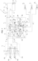
- Figure 1 discloses a hydraulic brake arrangement 1 according to the invention comprising a source 2 of fluid in pressure fluidly connected to left and right rear brakes 3a, 3b and front brakes 4, a power stage valve 5 which is fluidly interposed between source of fluid in pressure 2 and brakes 3a, 3b, 4 and a pilot stage 6 configured to control power stage valve 5.
- power stage valve 5 advantageously comprises a first opening 5a fluidly connected to source 2 via a related conduit 8, a second opening 5b fluidly connected to a discharge 9 via a related conduit 11, a third and a fourth openings 5c, 5d respectively fluidly connected via respective conduits 12, 13 to pilot stage 6, a fifth and a sixth openings 5e, 5f respectively fluidly connected via respective conduits 15, 16 to left and right rear brakes 3a, 3b, a seventh opening 5g fluidly connected to front brake 4 via a related conduit 17 and a eight opening 5h fluidly connected to pump 18 via a related conduit 14.
- Source 2 may comprise a pump 18 configured to supply fluid in pressure to power valve stage 5 via conduit 8 and at least an accumulator 19, fluidly connected to conduit 8 downstream with respect to pump 18, configured to supply fluid in pressure to power stage 5 via conduit 8 if pump 18 is not working/in fault.
- source 2 is advantageously provided with a check valve 21 configured to allow passage of fluid only from pump 18 towards power stage thereby denying passage of fluid from accumulator 19 to pump 18, if accumulator 19 is activated.
- Pilot stage 6 advantageously comprises a left and a right master cylinders 22a, 22b of known typology each provided with a brake pedal 23a, 23b. These latter, when pressed, are configured to impart a hydraulic pressure signal in conduits 12, 13 via master cylinders 22a, 22b.
- Master cylinders 22a, 22b are furthermore connected by a pressure balance conduit 24 described in further detail hereinafter.
- Power stage valve 5 is configured to receive a hydraulic signal from conduits 12, 13, proportional to the pressure received by master cylinders 22a, 22b in order to control the fluid coming for source 2 among brakes 3a, 3b and 4.
- power stage valve 5 comprises a gain valve 26 fluidly interposed between conduit 8, 11 and 14 and configured, in function of the balance of two hydraulic signals acting on opposite sides of the spool of gain valve 26, to increase the pressure of fluid coming from conduit 8 towards a first intermediate output conduit 27 or to drain fluid in first intermediate output conduit 27 to conduit 14, which is fluidly connected as loading signal to pump 18.
- gain valve 26 is a proportional hydraulic actuated valve having three ways and two-positions.
- First hydraulic signal acting on a first side valve 26 is taken by a conduit 28 on conduit 14 while a second hydraulic signal acting on the opposite side is taken by a conduit 29 fluidly connected to a shuttle valve 31 fluidly interposed between conduits 12 and 13.
- Second hydraulic signal is furthermore assisted by the force of an elastic element 32 acting against first hydraulic signal.
- Power stage valve 5 comprises a logic valve 33 fluidly interposed between first intermediate output conduit 27 and a second, a third and a fourth intermediate conduits 34a, 34b, 35 configured, in function of the balance of two hydraulic signals acting on opposite sides of the spool of logic valve 33, to divide the fluid coming from first intermediate output conduit 27 towards second, a third and a fourth intermediate conduits 34a, 34b, 35.
- logic valve 33 is a proportional hydraulic actuated valve having four ways and three positions.
- First hydraulic signal acting on a first side of valve 33 is taken by a conduit 36a derived by conduit 13 while a second hydraulic signal acting on the opposite side is taken by a conduit 36b derived by conduit 12.
- Both hydraulic signals are assisted by related springs 37a, 37b.
- first hydraulic signal acting on a first side of valve 33
- second hydraulic signal acting on the opposite side
- Both hydraulic signals are assisted by related springs 37a, 37b.
- first position wherein first hydraulic signal is greater than the second fluid may flow only towards conduit 34a
- in a second position, opposite with respect the first fluid may flow only towards conduit 34b while in a third intermediate position fluid is divided between conduits 34a, 34b and 35.
- Power stage valve 5 comprises a selection valve 38 fluidly interposed on conduit 35 between logic valve 33 and seventh opening 5g.
- Selection valve 38 is a two ways - two positions valve configured to assume a first position wherein there is free fluidic communication in conduit 35 and a second position wherein fluid may only flow from opening 5g towards logic valve 33 in function of two hydraulic signals acting on opposite sides of selection valve 38.
- first hydraulic signal is taken by a conduit 41 fluidly connected to output of valve 38 itself on conduit 35 and a second hydraulic signal is taken by a conduit 42 fluidly connected to conduit 29. Furthermore, first hydraulic signal is assisted by the force of an elastic element 43 acting on the same side of valve 38.
- Power stage valve 5 further comprises a pair of security valves 45a, 45b fluidly interposed between fifth and sixth openings 5e, 5f and conduits 34a, 34b and configured, in function of a balance between respective hydraulic signals, to allow fluidic communication between conduits 34a, 34b towards openings 5e, 5f or between conduits 12 and 13 with these latter or no fluidic communication at all.
- valve 45a it is a three position - three ways valve wherein a first hydraulic signal acts on a first side of the spool of valve 45a and derived by a conduit 46a fluidly connected to conduit 13 and a second hydraulic signal is derived by a conduit 48a fluidly connected to conduit 34a and by a conduit 49a fluidly connected to output of valve 45a which both acts on the opposite side of this latter. Furthermore, second hydraulic signal is assisted by the force imparted by an elastic element 47a.
- valve 45b comprise the same elements, having the same reference number together with letter b in figure 1 .
- valves 45a, 45b are positioned so that fluid may flow from logic valve 33 towards brakes 3a, 3b, while in a second opposite position, no fluid will pass. In an intermediate position fluid will pass from conduits 12, 13 towards brakes 3a, 3b.
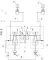
- Figure 2 discloses in greater detail the structure of balance pressure conduit 24 which can be fluidly interposed between master cylinders 22a, 22b.
- a simplified hydraulic brake arrangement 1' wherein output of master cylinders 22a, 22b is directly connected to right and left rear brakes 3a, 3b via conduits 3a', 3b'.
- balance pressure conduit 24 may be provided of a security balance device 50 configured to assume a first state into which fluid pass with a resistance from one to the other master cylinders 22a, 22 in order to balance a pressure difference between this latter and a second position into which fluid cannot pass between master cylinders.
- a security balance device 50 configured to assume a first state into which fluid pass with a resistance from one to the other master cylinders 22a, 22 in order to balance a pressure difference between this latter and a second position into which fluid cannot pass between master cylinders.
- such condition is a safety condition because it may happens that one side of the hydraulic circuit faults and, according to known balance devices, pressurized fluid in pressurized side of the circuit will discharge from the fault side.
- such security balance device 50 may comprise a pair of safety valves 51a, 51b, preferably in series one with respect to the other and each fluidly connected to the respective master cylinder 22a, 22b.
- safety valves 51a, 51b are maintained in open position by related springs 52a, 52b which defined a force which limit the difference of pressure between master cylinders 22a, 2b. If such force overcome such threshold, valves 51a, 51b move and avoid fluidic communication between master cylinders 22a, 22b.
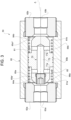
- security balance device 50 For greater clarity interpretation an exemplarily physic embodiment of security balance device 50 is shown in figure 3 .
- security balance device 50 comprise a spool 60 having a tubular shape around an axis A so that defining an inner volume 61.
- Spool 60 further comprises, housed inside volume 61 a pair of terminal caps 62a, 62b threaded to spool 60 so as to define respective openings 63a, 63b respectively fluidly connectable to pressure balance conduit 24, i.e. to master cylinders 22a, 22b, and to define respective shoulders 64a, 64b with respect to inner surface of spool 60 inside volume 61.
- security balance device 50 comprises a sliding element 65 housed inside volume 61 between caps 62a, 62b.
- Sliding element 65 comprises a main cylindrical portion 65a defining two extremities 65a', 65a" configured to cooperate at contact with shoulders 64a, 64b so as to close passage of fluid through respective openings 63a, 63b.
- Sliding element 65 further comprises a relief portion 65b extending radially from cylindrical portion 65a and configured to cooperate at contact in tight manner with inner surface of spool 60 so that divides volume 61 into a firs portion 61a faced to cap 62a and a second portion 61b faced to cap 62b.
- Security balance device 50 further comprises a pair of elastic elements 66a, 66b, e.g. coil springs, housed respectively in first and second portions 61a, 61b of volume 61 and comprising a first extremity cooperating with shoulders 64a, 64b and a second extremity cooperating with relief portion 65b. Stiffness of elastic elements 66a, 66b is set to be equal so that sliding element 65 is maintained in a substantially centered position inside volume 61 with respect to caps 62a, 62b.
- elastic elements 66a, 66b e.g. coil springs
- Sliding element 65 is provided with a channel system 70 configured to allow fluidic communication between first and second portion 61a, 61b of volume 61 and, accordingly, between first and second openings 63a, 63b.
- channel system 70 comprises a pair of radial conduits 71a, 71b passing through cylindrical portion 65a of sliding element 65 respectively in the portion of this latter placed inside first and second volume portions 61a, 61b.
- Channel system 70 further comprises an axial conduit 72, preferable coaxial to axis A, realized inside sliding element 65 and fluidly connecting radial conduits 71a, 71b.
- fluid in pressure is always available upstream to gain valve 26 which is, in rest position, positioned so that fluid cannot flow to conduit 27.
- conduit 27 fluid passes to conduit 27 and flows to logic valve 33.
- conduits 12 and 13 it divides, as said, flow of fluid among conduits 34a, 34b and 35.
- valve is positioned to allows fluidic communication towards all the three aforementioned conduits.
- conduits 34a, 34b and then to security valves 45a, 45b which are placed by the balance of hydraulic signals taken on conduits 46a, 48a, 49a and 46b, 48b, 49b so that they allow passage of fluid towards conduits 15, 16 and thereby to rear brakes 3a, 3b.
- conduit 35 and, then to selection valve 38, which allows, according to balance between hydraulic signals 42 and 41 fluid to pass to front brake 4.
- conduit 17 hydraulic signal taken by conduit 42 will push valve 38 so that flow of fluid cannot pass from logic valve 33 towards front brakes 4, thereby avoiding fluid dispersion.
- security balance device 50 is the following.
- any pressure variation in left or right side of brake arrangement 1' e.g. due to master brake cylinders 22a, 22b or to impulse braking force or to an impulse on brake pedals 23a, 23b, will generate a flow of fluid passing from one of openings 63a, 63b via first and second volumes 61a, 61 through channel system 70, i.e. passing from right side to left side (or vice versa).
- the passage between channel system 70 and between terminal cylindrical portions 65a', 65a" and shoulders 64a, 64b generates respective narrowing which smoots/dampens passage of fluid between openings 63a, 63b.
- Elastic elements 66a, 66b acts on sliding elements 65 if this latter moves for a greater pressure difference between openings 63a, 63b.
- the proposed layout is versatile, compact and allows braking with low pressure needed on brake pedals 23a, 24a while providing a great pressure fluid on brakes 3 and 4. Accordingly, comfort of the driver is increased.
- security valves 38, 45a, 45b allows to preserve braking function also in case of hydraulic deficiencies/failures from upstream to this latter, allowing directly braking by master cylinders 22a, 22b.
- valves are merely hydraulic actuated valves, accordingly there is no need for complex electronic actuation with related need of programmable control software.
- balance conduit 24 allows at the same time to balance pressure difference between first and second master cylinders 22a, 22b.
- conduit topography and signals derivations may be changed according to design conditions.
- safety balance device can be realized with a different layout and, similarly, spool 60 and sliding element 65.
Landscapes
- Engineering & Computer Science (AREA)
- Transportation (AREA)
- Mechanical Engineering (AREA)
- Valves And Accessory Devices For Braking Systems (AREA)
- Braking Arrangements (AREA)
Claims (11)
- Hydraulische Bremsanordnung (1) mit hinteren und/oder vorderen Bremsen (3, 4) eines Geländefahrzeugs, wobei die hydraulische Bremsanordnung (1) eine Quelle (2) von unter Druck stehendem Fluid, ein Leistungsstufenventil (5), das fluidisch zwischen der Quelle (2) und den hinteren und/oder vorderen Bremsen (3, 4) eingefügt ist, und eine Vorsteuerstufe (6) aufweist, wobei die Vorsteuerstufe (6) dazu eingerichtet ist, ein erstes und ein zweites hydraulisches Drucksignal zum Steuern des Leistungsstufenventils (5) bereitzustellen, um einen Fluidfluss von der Quelle (2) zu den hinteren und/oder vorderen Bremsen (3, 4) zu ermöglichen,dadurch gekennzeichnet, dassdas Leistungsstufenventil (5) ein Verstärkungsventil (26), ein Logik-Ventil (33) und eine Mehrzahl von Sicherheitsventilen (45a, 45b, 38) aufweist,wobei das Verstärkungsventil (26) fluidisch zwischen der Quelle (2) und dem Logik-Ventil (33) eingefügt und dazu eingerichtet ist, mindestens eine erste Stellung, in der es einen Fluidfluss zu dem Logik-Ventil (33) während ansteigendem Druckwert des letzteren ermöglicht, und eine zweite Stellung anzunehmen, in der ein Fluidfluss verhindert wird, in Abhängigkeit von dem größten Wert aus dem ersten und dem zweiten hydraulischen Drucksignal;wobei das Logik-Ventil (33) fluidisch zwischen dem Verstärkungsventil (26) und der Mehrzahl von Sicherheitsventilen (45, 45b, 38) eingefügt und dazu eingerichtet ist, den Fluidfluss zwischen mindestens einem der Mehrzahl von Sicherheitsventilen (45, 45b, 38) in Abhängigkeit von dem ersten und zweiten hydraulischen Drucksignal zu unterteilen;wobei die Mehrzahl von Sicherheitsventilen (45a, 45b, 38) fluidisch zwischen dem Logik-Ventil (33) und den hinteren und/oder vorderen Bremsen (3, 4) eingefügt und dazu eingerichtet sind, einen Fluidfluss von dem Logik-Ventil (33) zu den hinteren und/oder vorderen Bremsen (3, 4) zu ermöglichen oder einen Durchfluss des ersten und zweiten hydraulischen Drucksignals oder keinen Fluidfluss zu den hinteren und/oder vorderen Bremsen (3, 4) in Abhängigkeit von dem ersten und zweiten hydraulischen Drucksignal und mindestens einem hydraulischen Signal zu ermöglichen, das stromaufwärts oder stromabwärts bezüglich der Sicherheitsventile (45a, 45b, 38) entnommen wird.
- Hydraulische Bremsanordnung nach Anspruch 1, wobei das Verstärkungsventil (26), das Logik-Ventil (33) und die Mehrzahl von Sicherheitsventilen (45a, 45b, 38) ausschließlich hydraulisch gesteuerte Ventile sind.
- Hydraulische Bremsanordnung nach Anspruch 1 oder 2, wobei das Verstärkungsventil (26) ein Proportionalventil ist.
- Hydraulische Bremsanordnung nach einem der Ansprüche 1 bis 3, wobei die Mehrzahl von Sicherheitsventilen (45a, 45b, 38) ein drei Wege - drei Stellungs - Ventil (45a, 45b) aufweist, das dazu eingerichtet ist, eine erste Stellung, wobei kein Fluid von dem Logik-Ventil (33) zu den hinteren Bremsen (3) fließen kann, eine zweite Stellung, wobei Fluid von dem Logik-Ventil (33) zu den hinteren Bremsen (3) fließen kann, und eine dritte Stellung einzunehmen, wobei Fluid von dem ersten und zweiten hydraulischen Signal direkt zu den hinteren Bremsen (3) fließen kann, wobei die Stellungen in Abhängigkeit von dem ersten und zweiten hydraulischen Signal gegenüber einer Summe eines hydraulischen Signals, das stromaufwärts von den Sicherheitsventilen (45a, 45b) entnommen wird, und eines hydraulischen Signals, das stromabwärts von den Sicherheitsventilen (45a, 45b) entnommen wird, angenommen werden.
- Hydraulische Bremsanordnung nach einem der vorhergehenden Ansprüche 1 bis 4, wobei die Mehrzahl von Sicherheitsventilen (45a, 45b, 38) ein zwei Wege - zwei Stellungs - Ventil aufweist, das dazu eingerichtet ist, eine erste Stellung, die eine fluidische Kommunikation zwischen dem Logik-Ventil (33) und den vorderen Bremsen (4) zulässt, und eine zweiten Stellung, die keine fluidische Kommunikation von dem Logik-Ventil (33) zu den vorderen Bremsen (4) in Abhängigkeit von der größten Differenz zwischen dem ersten und zweiten hydraulischen Drucksignal und mindestens einem Signal zulässt, das stromabwärts bezüglich des Ventils (38) entnommen wird.
- Hydraulische Bremsanordnung nach einem der vorhergehenden Ansprüche, wobei die Fluidquelle (2) eine Pumpe (18) aufweist, die dazu eingerichtet ist, das Leistungsstufenventil (5) mit Fluid zu versorgen.
- Hydraulische Bremsanordnung nach Anspruch 6, die des Weiteren eine Speichereinrichtung (19), die fluidisch parallel zwischen der Pumpe (18) und dem Leistungsstufenventil (5) eingefügt ist.
- Hydraulische Bremsanordnung nach einem der vorhergehenden Ansprüche, wobei die Vorsteuerstufe (6) einen ersten und einen zweiten Masterzylinder (22a, 22b) aufweist, wobei der erste und zweite Masterzylinder (22a, 22b) dazu eingerichtet ist, das Leistungsstufenventil (5) mit dem ersten und dem zweiten hydraulischen Drucksignal zu versorgen, wenn ein Druck auf das Leistungsstufenventil (5) wirkt.
- Hydraulische Bremsanordnung nach Anspruch 8, wobei die Vorsteuerstufe (6) eine Druckausgleichsleitung (24) aufweist, die fluidisch zwischen dem ersten und einem zweiten Masterzylinder (22a, 22b) eingefügt ist, wobei die Vorsteuerstufe (6) ein Sicherheits-Ausgleichsgerät (50) aufweist, das in der Druckausgleichsleitung (24) fluidisch eingefügt und das dazu eingerichtet ist, eine fluidische Kommunikation zwischen dem ersten und einem zweiten Masterzylinder (22a, 22b) nur unterhalb eines vorbestimmten Druckdifferenzniveaus zwischen dem ersten und zweiten Masterzylinder (22a, 22b) zuzulassen.
- Hydraulische Bremsanordnung nach Anspruch 9, wobei das Sicherheits-Ausgleichsgerät (50) zwei Wege - zwei Stellungs - Ventile (51a, 51b) aufweist, die bezüglich eines in der Druckausgleichsleitung (24) befindlichen fluidisch in Serie sind.
- Hydraulische Bremsanordnung nach Anspruch 10, wobei die Ventile (51a, 51b) fluidisch gegen eine Kraft eines elastischen Elements (52a, 52b) von hydraulischen Signalen betätigt werden, die stromaufwärts und stromabwärts bezüglich des Ventils (51a, 51b) entnommen werden.
Applications Claiming Priority (1)
| Application Number | Priority Date | Filing Date | Title |
|---|---|---|---|
| IT102019000013680A IT201900013680A1 (it) | 2019-08-01 | 2019-08-01 | Disposizione idraulica di freno migliorata per un veicolo fuoristrada |
Publications (2)
| Publication Number | Publication Date |
|---|---|
| EP3771602A1 EP3771602A1 (de) | 2021-02-03 |
| EP3771602B1 true EP3771602B1 (de) | 2023-05-03 |
Family
ID=68653543
Family Applications (1)
| Application Number | Title | Priority Date | Filing Date |
|---|---|---|---|
| EP20188504.3A Active EP3771602B1 (de) | 2019-08-01 | 2020-07-30 | Verbesserte hydraulische bremsanordnung für ein geländefahrzeug |
Country Status (2)
| Country | Link |
|---|---|
| EP (1) | EP3771602B1 (de) |
| IT (1) | IT201900013680A1 (de) |
Cited By (1)
| Publication number | Priority date | Publication date | Assignee | Title |
|---|---|---|---|---|
| IT202300024552A1 (it) * | 2023-11-20 | 2025-05-20 | Cnh Ind Italia Spa | Sistema di frenatura migliorato per un veicolo da lavoro, relativo metodo di controllo e relativo veicolo da lavoro |
Family Cites Families (2)
| Publication number | Priority date | Publication date | Assignee | Title |
|---|---|---|---|---|
| WO2016027242A1 (en) * | 2014-08-20 | 2016-02-25 | Vhit S.P.A. | Braking system for agricultural vehicles or the like and manufacturing method thereof |
| US10556575B2 (en) * | 2015-03-04 | 2020-02-11 | Agco International Gmbh | Braking system |
-
2019
- 2019-08-01 IT IT102019000013680A patent/IT201900013680A1/it unknown
-
2020
- 2020-07-30 EP EP20188504.3A patent/EP3771602B1/de active Active
Cited By (2)
| Publication number | Priority date | Publication date | Assignee | Title |
|---|---|---|---|---|
| IT202300024552A1 (it) * | 2023-11-20 | 2025-05-20 | Cnh Ind Italia Spa | Sistema di frenatura migliorato per un veicolo da lavoro, relativo metodo di controllo e relativo veicolo da lavoro |
| EP4556329A1 (de) * | 2023-11-20 | 2025-05-21 | CNH Industrial Italia S.p.A. | Verbessertes bremssystem für ein arbeitsfahrzeug, verfahren zur steuerung dafür und zugehöriges arbeitsfahrzeug |
Also Published As
| Publication number | Publication date |
|---|---|
| EP3771602A1 (de) | 2021-02-03 |
| IT201900013680A1 (it) | 2021-02-01 |
Similar Documents
| Publication | Publication Date | Title |
|---|---|---|
| EP2892770B1 (de) | Bremsanlage für kraftfahrzeuge sowie verfahren zum betrieb einer bremsanlage | |
| EP2038153B1 (de) | Betriebsvorrichtung | |
| CN111231918A (zh) | 冗余液压压力产生式车辆电动液压制动系统及其操作方法 | |
| EP3604056B1 (de) | Servobremsventil | |
| CN103140398A (zh) | 用于通过两个制动踏板在车辆内控制制动的液压装置 | |
| EP3771602B1 (de) | Verbesserte hydraulische bremsanordnung für ein geländefahrzeug | |
| US7093911B2 (en) | Floating piston for augmenting pressurized fluid flow during vehicle braking operations | |
| US3459000A (en) | Dual-network hydraulic system and valve arrangement for controlling same | |
| US3977731A (en) | Fluid pressure control device with a failure alarm for a vehicle brake system | |
| EP1722109B1 (de) | Ruckfreies Ventil | |
| CN101119865A (zh) | 主动底盘稳定系统 | |
| CN113165624B (zh) | 用于非道路车辆的液压制动装置 | |
| JP2000108877A (ja) | ブレーキ液圧制御システム用シリンダ装置 | |
| US4371215A (en) | Dual type hydraulic circuit in a vehicle brake system | |
| EP4172010B1 (de) | Verbesserte hydraulische anordnung für die steuerung eines bremskraftverstärkers für arbeitsfahrzeuge | |
| EP4188763B1 (de) | Verbesserte hydraulische bremsanordnung für geländefahrzeug | |
| EP4157685B1 (de) | Verbesserte verstärkte bremssteuereinrichtung für arbeitsfahrzeuge | |
| EP3760458B1 (de) | Aktive hydraulische federungseinrichtung für ein geländefähiges fahrzeug | |
| EP3718840B1 (de) | Verbessertes sicherheitsventil für eine hydraulische bremsanlage | |
| JP5871136B2 (ja) | ブレーキ制御装置 | |
| USRE25162E (en) | Automotive vehicle power brake em- | |
| DE60130269T2 (de) | Hydraulischer Bremskraftverstärker | |
| JP2736101B2 (ja) | アンチスキッドブレーキ装置 | |
| EP3243715B1 (de) | Hydraulischer verteiler zum bremsen eines geräteanhängers | |
| US4076324A (en) | Brake system |
Legal Events
| Date | Code | Title | Description |
|---|---|---|---|
| PUAI | Public reference made under article 153(3) epc to a published international application that has entered the european phase |
Free format text: ORIGINAL CODE: 0009012 |
|
| STAA | Information on the status of an ep patent application or granted ep patent |
Free format text: STATUS: THE APPLICATION HAS BEEN PUBLISHED |
|
| AK | Designated contracting states |
Kind code of ref document: A1 Designated state(s): AL AT BE BG CH CY CZ DE DK EE ES FI FR GB GR HR HU IE IS IT LI LT LU LV MC MK MT NL NO PL PT RO RS SE SI SK SM TR |
|
| AX | Request for extension of the european patent |
Extension state: BA ME |
|
| STAA | Information on the status of an ep patent application or granted ep patent |
Free format text: STATUS: REQUEST FOR EXAMINATION WAS MADE |
|
| 17P | Request for examination filed |
Effective date: 20210803 |
|
| RBV | Designated contracting states (corrected) |
Designated state(s): AL AT BE BG CH CY CZ DE DK EE ES FI FR GB GR HR HU IE IS IT LI LT LU LV MC MK MT NL NO PL PT RO RS SE SI SK SM TR |
|
| GRAP | Despatch of communication of intention to grant a patent |
Free format text: ORIGINAL CODE: EPIDOSNIGR1 |
|
| STAA | Information on the status of an ep patent application or granted ep patent |
Free format text: STATUS: GRANT OF PATENT IS INTENDED |
|
| INTG | Intention to grant announced |
Effective date: 20221111 |
|
| GRAS | Grant fee paid |
Free format text: ORIGINAL CODE: EPIDOSNIGR3 |
|
| GRAA | (expected) grant |
Free format text: ORIGINAL CODE: 0009210 |
|
| STAA | Information on the status of an ep patent application or granted ep patent |
Free format text: STATUS: THE PATENT HAS BEEN GRANTED |
|
| AK | Designated contracting states |
Kind code of ref document: B1 Designated state(s): AL AT BE BG CH CY CZ DE DK EE ES FI FR GB GR HR HU IE IS IT LI LT LU LV MC MK MT NL NO PL PT RO RS SE SI SK SM TR |
|
| REG | Reference to a national code |
Ref country code: GB Ref legal event code: FG4D |
|
| REG | Reference to a national code |
Ref country code: DE Ref legal event code: R096 Ref document number: 602020010311 Country of ref document: DE |
|
| REG | Reference to a national code |
Ref country code: AT Ref legal event code: REF Ref document number: 1564336 Country of ref document: AT Kind code of ref document: T Effective date: 20230515 Ref country code: CH Ref legal event code: EP |
|
| REG | Reference to a national code |
Ref country code: IE Ref legal event code: FG4D |
|
| RAP4 | Party data changed (patent owner data changed or rights of a patent transferred) |
Owner name: CNH INDUSTRIAL ITALIA S.P.A. |
|
| REG | Reference to a national code |
Ref country code: LT Ref legal event code: MG9D |
|
| REG | Reference to a national code |
Ref country code: NL Ref legal event code: MP Effective date: 20230503 |
|
| REG | Reference to a national code |
Ref country code: AT Ref legal event code: MK05 Ref document number: 1564336 Country of ref document: AT Kind code of ref document: T Effective date: 20230503 |
|
| PG25 | Lapsed in a contracting state [announced via postgrant information from national office to epo] |
Ref country code: SE Free format text: LAPSE BECAUSE OF FAILURE TO SUBMIT A TRANSLATION OF THE DESCRIPTION OR TO PAY THE FEE WITHIN THE PRESCRIBED TIME-LIMIT Effective date: 20230503 Ref country code: PT Free format text: LAPSE BECAUSE OF FAILURE TO SUBMIT A TRANSLATION OF THE DESCRIPTION OR TO PAY THE FEE WITHIN THE PRESCRIBED TIME-LIMIT Effective date: 20230904 Ref country code: NO Free format text: LAPSE BECAUSE OF FAILURE TO SUBMIT A TRANSLATION OF THE DESCRIPTION OR TO PAY THE FEE WITHIN THE PRESCRIBED TIME-LIMIT Effective date: 20230803 Ref country code: NL Free format text: LAPSE BECAUSE OF FAILURE TO SUBMIT A TRANSLATION OF THE DESCRIPTION OR TO PAY THE FEE WITHIN THE PRESCRIBED TIME-LIMIT Effective date: 20230503 Ref country code: ES Free format text: LAPSE BECAUSE OF FAILURE TO SUBMIT A TRANSLATION OF THE DESCRIPTION OR TO PAY THE FEE WITHIN THE PRESCRIBED TIME-LIMIT Effective date: 20230503 Ref country code: AT Free format text: LAPSE BECAUSE OF FAILURE TO SUBMIT A TRANSLATION OF THE DESCRIPTION OR TO PAY THE FEE WITHIN THE PRESCRIBED TIME-LIMIT Effective date: 20230503 |
|
| PG25 | Lapsed in a contracting state [announced via postgrant information from national office to epo] |
Ref country code: RS Free format text: LAPSE BECAUSE OF FAILURE TO SUBMIT A TRANSLATION OF THE DESCRIPTION OR TO PAY THE FEE WITHIN THE PRESCRIBED TIME-LIMIT Effective date: 20230503 Ref country code: PL Free format text: LAPSE BECAUSE OF FAILURE TO SUBMIT A TRANSLATION OF THE DESCRIPTION OR TO PAY THE FEE WITHIN THE PRESCRIBED TIME-LIMIT Effective date: 20230503 Ref country code: LV Free format text: LAPSE BECAUSE OF FAILURE TO SUBMIT A TRANSLATION OF THE DESCRIPTION OR TO PAY THE FEE WITHIN THE PRESCRIBED TIME-LIMIT Effective date: 20230503 Ref country code: LT Free format text: LAPSE BECAUSE OF FAILURE TO SUBMIT A TRANSLATION OF THE DESCRIPTION OR TO PAY THE FEE WITHIN THE PRESCRIBED TIME-LIMIT Effective date: 20230503 Ref country code: IS Free format text: LAPSE BECAUSE OF FAILURE TO SUBMIT A TRANSLATION OF THE DESCRIPTION OR TO PAY THE FEE WITHIN THE PRESCRIBED TIME-LIMIT Effective date: 20230903 Ref country code: HR Free format text: LAPSE BECAUSE OF FAILURE TO SUBMIT A TRANSLATION OF THE DESCRIPTION OR TO PAY THE FEE WITHIN THE PRESCRIBED TIME-LIMIT Effective date: 20230503 Ref country code: GR Free format text: LAPSE BECAUSE OF FAILURE TO SUBMIT A TRANSLATION OF THE DESCRIPTION OR TO PAY THE FEE WITHIN THE PRESCRIBED TIME-LIMIT Effective date: 20230804 |
|
| PG25 | Lapsed in a contracting state [announced via postgrant information from national office to epo] |
Ref country code: FI Free format text: LAPSE BECAUSE OF FAILURE TO SUBMIT A TRANSLATION OF THE DESCRIPTION OR TO PAY THE FEE WITHIN THE PRESCRIBED TIME-LIMIT Effective date: 20230503 |
|
| PG25 | Lapsed in a contracting state [announced via postgrant information from national office to epo] |
Ref country code: SK Free format text: LAPSE BECAUSE OF FAILURE TO SUBMIT A TRANSLATION OF THE DESCRIPTION OR TO PAY THE FEE WITHIN THE PRESCRIBED TIME-LIMIT Effective date: 20230503 |
|
| PG25 | Lapsed in a contracting state [announced via postgrant information from national office to epo] |
Ref country code: SM Free format text: LAPSE BECAUSE OF FAILURE TO SUBMIT A TRANSLATION OF THE DESCRIPTION OR TO PAY THE FEE WITHIN THE PRESCRIBED TIME-LIMIT Effective date: 20230503 Ref country code: SK Free format text: LAPSE BECAUSE OF FAILURE TO SUBMIT A TRANSLATION OF THE DESCRIPTION OR TO PAY THE FEE WITHIN THE PRESCRIBED TIME-LIMIT Effective date: 20230503 Ref country code: RO Free format text: LAPSE BECAUSE OF FAILURE TO SUBMIT A TRANSLATION OF THE DESCRIPTION OR TO PAY THE FEE WITHIN THE PRESCRIBED TIME-LIMIT Effective date: 20230503 Ref country code: EE Free format text: LAPSE BECAUSE OF FAILURE TO SUBMIT A TRANSLATION OF THE DESCRIPTION OR TO PAY THE FEE WITHIN THE PRESCRIBED TIME-LIMIT Effective date: 20230503 Ref country code: DK Free format text: LAPSE BECAUSE OF FAILURE TO SUBMIT A TRANSLATION OF THE DESCRIPTION OR TO PAY THE FEE WITHIN THE PRESCRIBED TIME-LIMIT Effective date: 20230503 Ref country code: CZ Free format text: LAPSE BECAUSE OF FAILURE TO SUBMIT A TRANSLATION OF THE DESCRIPTION OR TO PAY THE FEE WITHIN THE PRESCRIBED TIME-LIMIT Effective date: 20230503 |
|
| REG | Reference to a national code |
Ref country code: DE Ref legal event code: R097 Ref document number: 602020010311 Country of ref document: DE |
|
| PG25 | Lapsed in a contracting state [announced via postgrant information from national office to epo] |
Ref country code: MC Free format text: LAPSE BECAUSE OF FAILURE TO SUBMIT A TRANSLATION OF THE DESCRIPTION OR TO PAY THE FEE WITHIN THE PRESCRIBED TIME-LIMIT Effective date: 20230503 |
|
| PG25 | Lapsed in a contracting state [announced via postgrant information from national office to epo] |
Ref country code: MC Free format text: LAPSE BECAUSE OF FAILURE TO SUBMIT A TRANSLATION OF THE DESCRIPTION OR TO PAY THE FEE WITHIN THE PRESCRIBED TIME-LIMIT Effective date: 20230503 |
|
| REG | Reference to a national code |
Ref country code: CH Ref legal event code: PL |
|
| PLBE | No opposition filed within time limit |
Free format text: ORIGINAL CODE: 0009261 |
|
| STAA | Information on the status of an ep patent application or granted ep patent |
Free format text: STATUS: NO OPPOSITION FILED WITHIN TIME LIMIT |
|
| REG | Reference to a national code |
Ref country code: BE Ref legal event code: MM Effective date: 20230731 |
|
| PG25 | Lapsed in a contracting state [announced via postgrant information from national office to epo] |
Ref country code: LU Free format text: LAPSE BECAUSE OF NON-PAYMENT OF DUE FEES Effective date: 20230730 |
|
| PG25 | Lapsed in a contracting state [announced via postgrant information from national office to epo] |
Ref country code: LU Free format text: LAPSE BECAUSE OF NON-PAYMENT OF DUE FEES Effective date: 20230730 |
|
| 26N | No opposition filed |
Effective date: 20240206 |
|
| REG | Reference to a national code |
Ref country code: IE Ref legal event code: MM4A |
|
| PG25 | Lapsed in a contracting state [announced via postgrant information from national office to epo] |
Ref country code: CH Free format text: LAPSE BECAUSE OF NON-PAYMENT OF DUE FEES Effective date: 20230731 |
|
| PG25 | Lapsed in a contracting state [announced via postgrant information from national office to epo] |
Ref country code: SI Free format text: LAPSE BECAUSE OF FAILURE TO SUBMIT A TRANSLATION OF THE DESCRIPTION OR TO PAY THE FEE WITHIN THE PRESCRIBED TIME-LIMIT Effective date: 20230503 |
|
| PG25 | Lapsed in a contracting state [announced via postgrant information from national office to epo] |
Ref country code: SI Free format text: LAPSE BECAUSE OF FAILURE TO SUBMIT A TRANSLATION OF THE DESCRIPTION OR TO PAY THE FEE WITHIN THE PRESCRIBED TIME-LIMIT Effective date: 20230503 Ref country code: BE Free format text: LAPSE BECAUSE OF NON-PAYMENT OF DUE FEES Effective date: 20230731 |
|
| PG25 | Lapsed in a contracting state [announced via postgrant information from national office to epo] |
Ref country code: IE Free format text: LAPSE BECAUSE OF NON-PAYMENT OF DUE FEES Effective date: 20230730 |
|
| PG25 | Lapsed in a contracting state [announced via postgrant information from national office to epo] |
Ref country code: IE Free format text: LAPSE BECAUSE OF NON-PAYMENT OF DUE FEES Effective date: 20230730 |
|
| PG25 | Lapsed in a contracting state [announced via postgrant information from national office to epo] |
Ref country code: BG Free format text: LAPSE BECAUSE OF FAILURE TO SUBMIT A TRANSLATION OF THE DESCRIPTION OR TO PAY THE FEE WITHIN THE PRESCRIBED TIME-LIMIT Effective date: 20230503 |
|
| PG25 | Lapsed in a contracting state [announced via postgrant information from national office to epo] |
Ref country code: BG Free format text: LAPSE BECAUSE OF FAILURE TO SUBMIT A TRANSLATION OF THE DESCRIPTION OR TO PAY THE FEE WITHIN THE PRESCRIBED TIME-LIMIT Effective date: 20230503 |
|
| PG25 | Lapsed in a contracting state [announced via postgrant information from national office to epo] |
Ref country code: CY Free format text: LAPSE BECAUSE OF FAILURE TO SUBMIT A TRANSLATION OF THE DESCRIPTION OR TO PAY THE FEE WITHIN THE PRESCRIBED TIME-LIMIT; INVALID AB INITIO Effective date: 20200730 |
|
| PG25 | Lapsed in a contracting state [announced via postgrant information from national office to epo] |
Ref country code: HU Free format text: LAPSE BECAUSE OF FAILURE TO SUBMIT A TRANSLATION OF THE DESCRIPTION OR TO PAY THE FEE WITHIN THE PRESCRIBED TIME-LIMIT; INVALID AB INITIO Effective date: 20200730 |
|
| PGFP | Annual fee paid to national office [announced via postgrant information from national office to epo] |
Ref country code: DE Payment date: 20250728 Year of fee payment: 6 |
|
| PGFP | Annual fee paid to national office [announced via postgrant information from national office to epo] |
Ref country code: IT Payment date: 20250721 Year of fee payment: 6 |
|
| PGFP | Annual fee paid to national office [announced via postgrant information from national office to epo] |
Ref country code: GB Payment date: 20250722 Year of fee payment: 6 |
|
| PGFP | Annual fee paid to national office [announced via postgrant information from national office to epo] |
Ref country code: FR Payment date: 20250725 Year of fee payment: 6 |
|
| PG25 | Lapsed in a contracting state [announced via postgrant information from national office to epo] |
Ref country code: TR Free format text: LAPSE BECAUSE OF FAILURE TO SUBMIT A TRANSLATION OF THE DESCRIPTION OR TO PAY THE FEE WITHIN THE PRESCRIBED TIME-LIMIT Effective date: 20230503 |