EP3771519B1 - Schraubvorrichtung mit integrierten erfassungsmitteln - Google Patents
Schraubvorrichtung mit integrierten erfassungsmitteln Download PDFInfo
- Publication number
- EP3771519B1 EP3771519B1 EP19189731.3A EP19189731A EP3771519B1 EP 3771519 B1 EP3771519 B1 EP 3771519B1 EP 19189731 A EP19189731 A EP 19189731A EP 3771519 B1 EP3771519 B1 EP 3771519B1
- Authority
- EP
- European Patent Office
- Prior art keywords
- force
- output
- detection means
- force transducer
- torque
- Prior art date
- Legal status (The legal status is an assumption and is not a legal conclusion. Google has not performed a legal analysis and makes no representation as to the accuracy of the status listed.)
- Active
Links
Images


Classifications
-
- B—PERFORMING OPERATIONS; TRANSPORTING
- B25—HAND TOOLS; PORTABLE POWER-DRIVEN TOOLS; MANIPULATORS
- B25B—TOOLS OR BENCH DEVICES NOT OTHERWISE PROVIDED FOR, FOR FASTENING, CONNECTING, DISENGAGING, OR HOLDING
- B25B13/00—Spanners; Wrenches
- B25B13/48—Spanners; Wrenches for special purposes
-
- B—PERFORMING OPERATIONS; TRANSPORTING
- B25—HAND TOOLS; PORTABLE POWER-DRIVEN TOOLS; MANIPULATORS
- B25B—TOOLS OR BENCH DEVICES NOT OTHERWISE PROVIDED FOR, FOR FASTENING, CONNECTING, DISENGAGING, OR HOLDING
- B25B13/00—Spanners; Wrenches
- B25B13/48—Spanners; Wrenches for special purposes
- B25B13/481—Spanners; Wrenches for special purposes for operating in areas having limited access
-
- B—PERFORMING OPERATIONS; TRANSPORTING
- B25—HAND TOOLS; PORTABLE POWER-DRIVEN TOOLS; MANIPULATORS
- B25B—TOOLS OR BENCH DEVICES NOT OTHERWISE PROVIDED FOR, FOR FASTENING, CONNECTING, DISENGAGING, OR HOLDING
- B25B17/00—Hand-driven gear-operated wrenches or screwdrivers
-
- B—PERFORMING OPERATIONS; TRANSPORTING
- B25—HAND TOOLS; PORTABLE POWER-DRIVEN TOOLS; MANIPULATORS
- B25B—TOOLS OR BENCH DEVICES NOT OTHERWISE PROVIDED FOR, FOR FASTENING, CONNECTING, DISENGAGING, OR HOLDING
- B25B17/00—Hand-driven gear-operated wrenches or screwdrivers
- B25B17/02—Hand-driven gear-operated wrenches or screwdrivers providing for torque amplification
-
- B—PERFORMING OPERATIONS; TRANSPORTING
- B25—HAND TOOLS; PORTABLE POWER-DRIVEN TOOLS; MANIPULATORS
- B25B—TOOLS OR BENCH DEVICES NOT OTHERWISE PROVIDED FOR, FOR FASTENING, CONNECTING, DISENGAGING, OR HOLDING
- B25B23/00—Details of, or accessories for, spanners, wrenches, screwdrivers
- B25B23/14—Arrangement of torque limiters or torque indicators in wrenches or screwdrivers
- B25B23/142—Arrangement of torque limiters or torque indicators in wrenches or screwdrivers specially adapted for hand operated wrenches or screwdrivers
- B25B23/1422—Arrangement of torque limiters or torque indicators in wrenches or screwdrivers specially adapted for hand operated wrenches or screwdrivers torque indicators or adjustable torque limiters
- B25B23/1425—Arrangement of torque limiters or torque indicators in wrenches or screwdrivers specially adapted for hand operated wrenches or screwdrivers torque indicators or adjustable torque limiters by electrical means
Definitions
- the present invention relates to a screwing device for applying a torque to a screwing partner with integrated detection means for an output torque.
- screwing devices with flat output means are generally known. These are gear units - usually accommodated in a flat housing - with a drive usually provided at one end and an output drive provided at the opposite end, on which a screw partner such as a screw to be subjected to a torque can be suitably detachably attached. Screwing devices of this type are used in particular for screwing or assembly work in which a screwing partner is difficult to reach due to spatial installation conditions.
- a generic screw is already from the WO 2018/188829 A1 known.
- additional axial bearings must be provided, which increases the structural complexity of the structural arrangement in the flywheel output means.
- the known detection means require additional space in the geared offset drive means.
- the GB 2 383 282 A discloses a torque transmission device having a hollow shaft with external teeth for connection to a bevel gear and a central shaft guided in the hollow shaft, wherein a flexible cantilever beam arranged between the central shaft and a cup-like end section of the hollow shaft has torque sensors.
- the object of the present invention is to provide an improved screwing device based on the known prior art, which overcomes or at least significantly alleviates the aforementioned disadvantages of the prior art.
- a screwing device with alternative means for determining and/or monitoring the torque acting on a screwing partner on the output side is to be provided, which at the same time enables a cost-effective and compact design of the flat drive.
- a reliable torque determination and/or monitoring should be made possible.
- the invention also addresses other problems, which will become more apparent from the following description.
- the invention relates to a screwing device for applying a torque to a screwing partner, having flat output means which have an output that can be releasably connected to the screwing partner and a manually or mechanically connected one drive torque, preferably via an interposed angular and/or bevel gearing, and detection means for providing measured values for determining and/or monitoring an output torque acting on the screwing partner on the output side, characterized in that the detection means provided in a housing of the flat output means so are designed such that they can detect a radial force and/or tangential force acting on a preferably straight-toothed gear wheel connecting the drive and the output of the flat output means in a torque-transmitting manner and can provide this for preferably electronic signal evaluation.
- the design of the detection means according to the invention which are integrated in the housing of the offset output means and detect a radial force and/or tangential force or circumferential force of a gear wheel in the offset output means that interacts with the detection means, provides a structurally simple solution for reliably providing measured values for determining and/or Monitoring of the output torque acting on a screwing partner on the output side.
- the space required in the geared offset drive means can be minimized compared to the known prior art.
- the design of the screw device according to the invention enables cost-effective production and simplified maintenance.
- straight toothing is provided for the gear wheel interacting with the detection means, an increase in the efficiency of the flat output means is achieved.
- the above-mentioned measured values for determining and/or monitoring the output torque are preferably understood to mean the radial force and/or tangential force detected by the detection means or measured values or measured value signals representing these.
- the described radial and/or tangential force acting on the gear relates to a respective radial force and/or tangential force applied to the gear, in particular during an operative connection with other gears or teeth meshing therewith.
- the radial and/or tangential force acting on the gear relates to a bearing reaction force of the gear in the radial and/or tangential direction that can be detected by the detection means.
- the respective radial force and/or tangential force is detected which, during torque transmission, occurs on the gear wheel connected to the detection means on the bearing or on the bearing an axis of rotation of the gearwheel which is preferably fixed in the housing.
- the radial force and/or tangential force preferably relates to a force which is present in a plane essentially perpendicular to the axis of rotation of the gear wheel and/or the main axis of the offset gear.
- the detection means are designed in such a way that they detect a radial force in or along a line of action in which the preferably rectified tangential or circumferential forces applied to the gearwheel are or can be combined to form a resultant force.
- the radial force recorded here is a force applied to the gear wheel or bearing reaction force of the gear wheel.
- the gear wheel interacting with the detection means according to the invention has straight teeth, this preferably only has a rotary force input and thus also only radial and/or tangential forces acting on the gear wheel during the operative connection or interaction with other gear wheels or toothings of the offset output means meshing with it. There are preferably no axial forces, i.e. forces along an axis of rotation of the gear.
- a measured value signal that reliably represents and/or monitors the torque on the output side can be provided by the detection means for preferably electronic signal evaluation.
- axial forces also occur on the gear wheel or bearing reaction forces acting in the axial direction. These are preferably not caused by the detection means according to the invention recorded. Nevertheless, a measured value signal that reliably monitors the torque on the output side can be provided by the detection means for preferably electronic signal evaluation. In this case, a deviation in the output-side torque can be inferred in particular from a deviation in the detected radial and/or tangential forces.
- the gear wheel cooperating with the detection means according to the invention is arranged between a geared drive assembly of the flat output means and a geared output assembly of the flat output means.
- the gear wheel that interacts with the detection means according to the invention is preferably designed as a gear wheel that interacts or meshes directly with the output assembly.
- the gear wheel interacting with the detection means according to the invention can be directly encompassed by the output assembly.
- the straight-toothed gear itself can form the output assembly of the flat output means.
- the gear output means have a plurality of gears which form a gear arrangement between the input and the output of the gear output means.
- the gear wheel interacting with the detection means according to the invention is preferably one of the gear wheels forming the gear arrangement.
- the gear arrangement can have straight gearing or helical gearing.
- the gear arrangement can also have angle, bevel and/or curved teeth.
- the flat output means have a plurality, i.e. at least two, preferably at least three, straight-toothed or helical-toothed gears.
- the flat output means have only straight-toothed gears.
- the flat output means can also include at least partially helical gears.
- the axes of rotation of the gear wheels of the flat output means preferably all extend in one plane. The axes of rotation preferably run parallel to one another and extend through the flat sides of the housing of the offset output.
- the housing of the offset output preferably has two parallel flat sides or opposite flat outer surfaces. These are preferably free of projections or elevations.
- the housing is preferably designed in two parts, with two opposite housing halves.
- the maximum width of the housing is preferably less than 30mm, more preferably less than 20mm.
- the cog wheel interacting with the detection means preferably has a bearing axis which is arranged in the housing in a fixed, in particular non-rotatable manner, on which a ring gear of the cog wheel is mounted so that it can rotate freely, preferably by means of a needle bearing.
- the detection means preferably have at least one force transducer. This is preferably firmly connected to a bearing or to the bearing axis of the gear wheel, in particular in a non-rotatable manner, or is formed integrally therewith.
- the force transducer is preferably arranged in a torsion-proof manner between the bearing axis and the housing of the flywheel output means.
- the force transducer can be secured against twisting relative to the housing by means of a suitable pin connection with a housing cover and/or by means of a corresponding shape in a housing cover recess.
- the force transducer is preferably arranged in a line of action of the resultant force applied to the gear wheel, which line of action extends radially to the gear wheel.
- This is preferably understood to mean a radially acting force in which the preferably rectified tangential or circumferential forces applied to the gear wheel are combined or can be combined to form a resultant force.
- the force transducer is preferably arranged in such a way that it can detect a radial force in or along a line of action.
- the force transducer is preferably in the form of a spoked wheel and, according to the invention, is essentially disc-shaped.
- the force transducer is preferably made from the same material as the associated gear wheel and/or the bearing axle of the gear wheel.
- the force transducer is preferably formed or arranged on an end face of the gear wheel.
- the force transducer can be arranged directly on a toothed edge of the gear wheel.
- two force transducers preferably of the same design, can be formed or arranged on opposite end faces of the gear wheel.
- the force transducer is preferably arranged in such a way that there is no transmission of force from the force transducer to the housing of the offset output means in the axial direction, i.e. in particular along an axis of rotation of the gear wheel.
- the force transducer can be arranged or designed coaxially with the associated gearwheel and/or rotationally symmetrically.
- the force transducer preferably has an outer diameter or a maximum radial extent which essentially corresponds to a root circle of the toothing of the associated straight-toothed Gear corresponds.
- the force transducer preferably has an axially extending thickness of 1 to 5 mm, more preferably between 1 and 2.5 mm.
- the force transducer has integrated force sensor means which are designed to detect a compressive and/or tensile force applied to the force transducer in the radial and/or tangential direction of the gear wheel or the force transducer.
- the force sensor means are preferably arranged in a radially extending line of action of the resultant force applied to the gear wheel.
- the force sensor means comprise at least two strain gauges on the force transducer.
- the strain gauges are arranged on spokes or struts of the force transducer that extend radially and lie opposite one another.
- the force sensor means can also have piezo elements.
- the force sensor means can comprise hydraulic or pneumatic pressure sensor means attached to or connected to the force transducer.
- the force transducer can have at least one or preferably two suitable chambers, for example in the form of recesses or cavities, in which a fluid suitable for hydraulic or pneumatic sensor pickup is arranged or introduced.
- the chambers are preferably arranged opposite one another in the force transducer and in a respective half of the force transducer.
- the force sensing means comprises a graphene attached to or integrated with the force transducer Polymer mass with variable electrical conductivity.
- the polymer mass is preferably formed by a graphene-containing viscoelastic polymer mass such as a silicone-based jumping putty with boron content.
- a graphene-containing viscoelastic polymer mass such as a silicone-based jumping putty with boron content.
- a measured value signal representing and/or monitoring the torque on the output side reliably and with a high measurement quality and accuracy can be provided by the above-mentioned sensor means for preferably electronic signal evaluation.
- the detection means can have means for wireless signal transmission of a measured value signal corresponding to the detected output torque and/or for monitoring this.
- the detection means can also have electronic interface and/or signal processing means and electrical energy supply means. The latter can be implemented as electrical generator means interacting with a movable, in particular rotating, component of the flat output means.
- the measured value signal provided by the detection means can be transmitted to a computing unit that is assigned to or can be connected to the screwing device, which evaluates the detected signal and, based thereon, calculates or calculates and/or monitors the respective output torque. For example, this can be based on Comparison tables and/or database information are provided. These can include, for example, measured values of the detection means determined in test series and the respective associated torque values, with which the respective output torque can be calculated or calculated and/or monitored based on the measured values provided.
- the arithmetic unit can be designed to detect a deviation from a definable setpoint and to output an alarm or information signal if the deviation is too large, for example preferably more than 10%, more preferably more than 5%.
- the flywheel gears according to the invention are preferably closed or open flywheel gears.
- the flywheel gear can be designed with or without an angle gear.
- the geared offset drive means can also have curved teeth, for example as part of an angular gear.
- the detection means according to the invention can also be assigned to a gear wheel with curved teeth or interact with it to detect the radial and/or tangential force acting on the gear wheel.
- the present invention relates to a preferably hand-held or stationary screwing system, having the screwing device as described above and drive torque generating means connected on the drive side to the flat output means.
- the torque generating means is preferably in the form of a manually operable or automatic screwdriver.
- a stationary screwing system is preferably understood to mean a screwing system which is permanently installed or installed in a production unit, for example a robot cell, and can preferably be operated by an automatic controller.
- the screwing device 10 shows a preferred embodiment of the screwing device 10 according to the invention for applying a torque to a screwing partner 20 such as a screw.
- the screwing device 10 comprises flat output means 1 having an output 1b that can be detachably connected to the screwing partner 20 and a drive 1a, which can be subjected to a drive torque manually or mechanically, for example via an interposed angle and/or bevel gearing 31.
- the screwing device 10 can preferably be selectively connected to a screwing tool 30, as a result of which the screwing system 40 according to the invention is formed.
- the screwing tool 30 can be a commercially available tool and can be motorized, e.g. The drive torque introduced in this way is transmitted by the flat output means 1 in the manner described below to a tool 32 arranged as an output 1b for screwing actuation of the screwing partner 20 .
- the screwing device 10 has a flat housing 30, which is preferably formed from essentially two housing halves 30a, 30b of essentially the same design.
- the housing 30 preferably has a maximum height or width b of 30mm, more preferably 20mm.
- the offset output means 1 have a drive assembly 2, for example, for interacting with the angle and/or bevel gearing 31 provided on the drive side, and an output assembly 3 for interacting with the screwing partner 20, for example via a tool 32 arranged on the output side connected thereto.
- the flywheel drive means 1 preferably have a plurality of gears 4a, 4b, 4c, 4d, 4e, which form a gear arrangement between the input 1a and the output 1b of the flywheel drive means 1.
- the gears are preferably straight-toothed gears which, for example, realize a gear ratio of 1:1.
- the gears can also deviate from the illustration in 2 be realized as helical gears. A different gear ratio can also be implemented.
- the gears are preferably arranged in the housing 30 with their axes parallel and extend linearly along a longitudinal extension of the housing 30 in which they are rotatably arranged.
- the gears can be partially included in the input or output assembly 2.3.
- the drive assembly 2 and the output assembly 3 each have a toothing or a gear wheel 4a, 4e, which is in operative connection with the remaining gear wheels of the transmission arrangement.
- the input and output assembly 2.3 can each be formed by a gear 4a, 4e.
- such flat output means 1 are provided and suitable for transmitting a maximum torque of approximately 200 Nm.
- the usual efficiency of such a straight-toothed gear arrangement is between approx. 85% and 95% (i.e. the ratio of an output-side torque at 4e to a drive-side torque at 4a).
- detection means 5 Arranged between the drive assembly 2 and the output assembly 3 are detection means 5 which are designed to provide measured values for determining and/or monitoring an output torque acting on the screwing partner 20 on the output side.
- the detection means 5 are associated with a preferably straight-toothed gear wheel 4d or are operatively connected to it.
- the gear wheel 4d connected to the detection means 5 is preferably arranged in mesh with the gear wheel 4e of the output assembly 3.
- the gear wheel 4d connected to the detection means 5 can also be included directly by the output assembly 3 or form it.
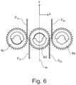
- FIG. 6 shows a principle sketch, in which the in 2 illustrated linear arrangement of the straight-toothed gear group 4c, 4d, 4e is shown schematically.
- the free section of the meshing gears 4c, 4d, 4e shown as an example shows that the respective tangential or circumferential forces F 1a , F 1b and F 2a , F 2b act in the Y-direction shown and are therefore essentially orthogonal when the teeth mesh extend to a direction X of the transmission arrangement 4c, 4d, 4e.
- the origin of forces in the meshing is shown as an example on both sides. The magnitude of the forces differs only by a possible loss of efficiency within a gear stage.
- the detection means 5 are therefore preferably arranged in the line of action of the resultant force applied to the gear wheel 4d or arranged in such a way that they can detect the forces occurring in or along the line of action.
- Figure 3a shows a perspective view of the gear wheel 4d and the associated or associated detection means 5.
- the detection means 5 have a preferably essentially disk-shaped force transducer 5a, for example in the form of a spoked wheel (see also 3c ), which is formed integrally with an axis of rotation 19 of the gear wheel 4a and/or is connected in a fixed manner, in particular non-rotatably.
- the force transducer 5a is mounted non-rotatably in the housing 30a, 30b, for example by means of axially arranged bores 9a, 9b and connecting pins (not shown) accommodated therein.
- the force transducer 5a can also be mounted in a form-locked manner in the housing.
- the force transducer 5a can have an outer shape, for example essentially trapezoidal (cf. 3d ), which can be received or stored in a corresponding recess of the housing 30a, 30b in a torsion-proof manner.
- the force transducer 5a is preferably arranged on an end face 6a of the gear wheel 4d or the axis of rotation 19 of the gear wheel 4d.
- the detection means 5 preferably have two force transducers 5a, preferably of the same design, which are arranged on two opposite end faces 6a, 6b of the gear wheel 4a or the axis of rotation 19 of the gear wheel 4d (cf. Figure 3b ).
- the gear wheel 4d preferably comprises the central axis of rotation 19 with a bore 19a arranged therein, which is designed for the preferably non-rotatable arrangement in the flat output means 1 and/or for guiding sensor lines or wiring 13 belonging to the detection means 5.
- the axle 19 preferably has an axially projecting section 19b at both ends, which is designed to support and/or connect to the at least one force transducer 5a.
- the section 19b can engage in a central bore 8 of the force transducer 5a, preferably in a torsion-proof manner.
- a spacer or drilling disc 21 can be arranged between the force transducer 5a and a main axle body of the axle 19 .
- a ring gear 22 of the gear wheel 4d is preferably arranged to be freely rotatable on the axis 19 by means of a needle bearing 23 .
- the force transducer 5a has a central bore 8 for connecting the force transducer 5a to the axis of rotation 19 and/or for guiding sensor lines 13 .
- the force transducer 5a preferably has a circular outer contour.
- An outer diameter d or a maximum radial extent of the force transducer 5a is preferably smaller or essentially corresponds to the root circle of the gear wheel 4d.
- a thickness t of the force transducer 5a is preferably between 1 and 5 mm, more preferably between 1 and 2.5 mm.
- the force transducer 5a has at least two preferably opposite radial struts or webs 7a, 7b and preferably substantially arc-shaped recesses 11a, 11b, 11c, 11d in between.
- the force transducer 5a can be formed from an inner circle 18a and an outer circle 18b which is coaxial thereto and has radially running struts or webs 7a, 7b, 7c, 7d.
- the force transducer 5a has integrated or attached force sensor means, which are designed to detect a compressive and/or tensile force in the radial and/or tangential direction to the gearwheel 4d applied to the force transducer and thus to the bearing axis 19 connected thereto in a rotationally fixed manner as a bearing reaction force.
- the force sensor means are formed by strain gauges 12a, 12b attached to the force transducer 5a.
- struts 7a, 7b of the force transducer 5a are arranged on the radially extending and preferably opposite struts 7a, 7b of the force transducer 5a and can thus in particular detect a pressure and/or tensile force acting in these struts during the interaction of the associated gear wheel 4d with the gear wheels 4c, 4e meshing therewith.
- the struts 7a, 7b or the force sensor means 12a, 12b are preferably arranged along or parallel to a line of action W of the resultant force applied to the gear wheel 4d in the respective gear arrangement (cf. also 6 ).
- a signal provided in an otherwise customary and known manner for subsequent processing and evaluation can be output through the sensor cabling 13 .
- the strain gauges as force sensor means generate a voltage change due to elastic deformation by radial forces, which is provided for electronic signal evaluation and in particular for determining and/or monitoring a torque on the output side.
- the device can also have means for wireless signal transmission (not shown).
- the signal evaluation can be carried out using computing means (not shown) which are assigned to or can be connected to the device and which, for example, calculate or monitor the associated or present torque on the basis of an output voltage signal. This can for example based on comparison tables stored in a database.
- the force sensor signal can be very reproduce or monitor the actual output-side torque conditions at the offset output means in a precise, interference-free and reproducible manner.
- Figures 4a and 4b show a further preferred embodiment of the detection means 5 according to the invention, wherein the force transducer 5a has hydraulic or pneumatic pressure sensor means.
- the force transducer(s) 5a has at least one or preferably two suitable chambers 14a, 14b in the form of recesses or cavities, in which a suitable fluid is arranged or introduced.
- the chambers 14a, 14b are preferably arranged opposite one another in the force transducer 5a and mirrored along an axis A which divides the force transducer 5a in half.
- a hydraulic or pneumatic pressure change in the chambers 14a, 14b occurring as a result of the interaction of the gear 4d with the gears 4c, 4e meshing with it can be detected by means of suitable pressure sensors assigned to the chambers 14a, 14b. Transmission to pressure sensors arranged externally to the force transducer 5a can take place by means of suitable lines 14c, 14d.
- the chambers 14a, 14b can each have a filling and/or ventilation opening 24 which can be selectively closed with an associated plug (not shown). The sensor means can then output a corresponding electronic signal, which can be used to infer the torque present at the gear wheel 4d.
- the detection means 5 preferably have two force transducers 5a, which are arranged on both end faces 6a, 6b of the gear wheel 4d or the axis of rotation 19.
- the respective chambers 14a, 14b are preferably connected or coupled by means of channels 25 preferably formed in the axis of rotation 19 or guided therein.
- FIG. 5 shows a further preferred embodiment of the detection means 5 according to the invention, wherein the force transducer 5a has a graphene-containing polymer mass with variable electrical conductivity as the sensor means.
- the force transducer 5a has at least one or preferably two suitable chambers 15a, 15b in the form of recesses or cavities, into which the graphene-containing polymer mass is introduced and which is contacted with the associated electrical lines 16a, 16b and 17a, 17b.
- the chambers 15a, 15b are preferably arranged mirrored along an axis B which divides the force transducer 5a in half.
- Radially extending spring elements 26 are preferably arranged as supporting structural elements within the chambers 15a, 15b.
Landscapes
- Engineering & Computer Science (AREA)
- Mechanical Engineering (AREA)
- Force Measurement Appropriate To Specific Purposes (AREA)
- Details Of Spanners, Wrenches, And Screw Drivers And Accessories (AREA)
- Glass Compositions (AREA)
- Reinforced Plastic Materials (AREA)
- Optical Measuring Cells (AREA)
Priority Applications (9)
| Application Number | Priority Date | Filing Date | Title |
|---|---|---|---|
| EP19189731.3A EP3771519B1 (de) | 2019-08-02 | 2019-08-02 | Schraubvorrichtung mit integrierten erfassungsmitteln |
| ES19189731T ES2943491T3 (es) | 2019-08-02 | 2019-08-02 | Dispositivo de atornillado con medios de detección integrados |
| EP23154666.4A EP4197696B1 (de) | 2019-08-02 | 2019-08-02 | Schraubvorrichtung mit integrierten erfassungsmitteln |
| ES23154666T ES3041661T3 (en) | 2019-08-02 | 2019-08-02 | Screwing device with integrated sensing means |
| KR1020227005602A KR102726000B1 (ko) | 2019-08-02 | 2020-06-18 | 검출 수단이 통합된 스크류 체결 장치 |
| CN202080061955.1A CN114375242A (zh) | 2019-08-02 | 2020-06-18 | 具有集成检测装置的拧紧设备 |
| JP2022506605A JP7602810B2 (ja) | 2019-08-02 | 2020-06-18 | 一体化された検出手段を備えるねじ締め装置 |
| US17/631,671 US12128530B2 (en) | 2019-08-02 | 2020-06-18 | Screw device having integrated detection means |
| PCT/EP2020/066949 WO2021023422A1 (de) | 2019-08-02 | 2020-06-18 | Schraubvorrichtung mit integrierten erfassungsmitteln |
Applications Claiming Priority (1)
| Application Number | Priority Date | Filing Date | Title |
|---|---|---|---|
| EP19189731.3A EP3771519B1 (de) | 2019-08-02 | 2019-08-02 | Schraubvorrichtung mit integrierten erfassungsmitteln |
Related Child Applications (2)
| Application Number | Title | Priority Date | Filing Date |
|---|---|---|---|
| EP23154666.4A Division EP4197696B1 (de) | 2019-08-02 | 2019-08-02 | Schraubvorrichtung mit integrierten erfassungsmitteln |
| EP23154666.4A Division-Into EP4197696B1 (de) | 2019-08-02 | 2019-08-02 | Schraubvorrichtung mit integrierten erfassungsmitteln |
Publications (2)
| Publication Number | Publication Date |
|---|---|
| EP3771519A1 EP3771519A1 (de) | 2021-02-03 |
| EP3771519B1 true EP3771519B1 (de) | 2023-03-15 |
Family
ID=67539326
Family Applications (2)
| Application Number | Title | Priority Date | Filing Date |
|---|---|---|---|
| EP19189731.3A Active EP3771519B1 (de) | 2019-08-02 | 2019-08-02 | Schraubvorrichtung mit integrierten erfassungsmitteln |
| EP23154666.4A Active EP4197696B1 (de) | 2019-08-02 | 2019-08-02 | Schraubvorrichtung mit integrierten erfassungsmitteln |
Family Applications After (1)
| Application Number | Title | Priority Date | Filing Date |
|---|---|---|---|
| EP23154666.4A Active EP4197696B1 (de) | 2019-08-02 | 2019-08-02 | Schraubvorrichtung mit integrierten erfassungsmitteln |
Country Status (7)
| Country | Link |
|---|---|
| US (1) | US12128530B2 (enExample) |
| EP (2) | EP3771519B1 (enExample) |
| JP (1) | JP7602810B2 (enExample) |
| KR (1) | KR102726000B1 (enExample) |
| CN (1) | CN114375242A (enExample) |
| ES (2) | ES3041661T3 (enExample) |
| WO (1) | WO2021023422A1 (enExample) |
Cited By (1)
| Publication number | Priority date | Publication date | Assignee | Title |
|---|---|---|---|---|
| US12151344B2 (en) * | 2019-07-24 | 2024-11-26 | Atlas Copco Industrial Technique Ab | Power tool attachment part |
Families Citing this family (13)
| Publication number | Priority date | Publication date | Assignee | Title |
|---|---|---|---|---|
| EP3771519B1 (de) * | 2019-08-02 | 2023-03-15 | Johannes Lübbering GmbH | Schraubvorrichtung mit integrierten erfassungsmitteln |
| SE545361C2 (en) * | 2021-08-23 | 2023-07-18 | Atlas Copco Ind Technique Ab | Arrangement for power tool, front part attachment and power tool |
| USD1012643S1 (en) * | 2021-12-21 | 2024-01-30 | Matco Tools Corporation | Ratchet pawl |
| USD1116673S1 (en) * | 2023-01-14 | 2026-03-10 | Harbor Freight Tools Usa, Inc. | Rachet sleeve |
| EP4410486A1 (en) * | 2023-02-01 | 2024-08-07 | Stanley Black & Decker MEA FZE | Torque wrench loadcell holder |
| USD1075449S1 (en) * | 2023-07-31 | 2025-05-20 | Wen-Tang Tsai | Ratchet socket of a skateboard wrench |
| CN117340828B (zh) * | 2023-11-06 | 2025-12-19 | 深圳市大寰机器人科技有限公司 | 电动螺丝批的转角传动机构、电动螺丝批和力矩测量方法 |
| USD1126706S1 (en) * | 2024-02-16 | 2026-05-19 | Stanley Black & Decker, Inc. | Gear for a hand tool |
| USD1123549S1 (en) * | 2024-02-16 | 2026-04-28 | Stanley Black & Decker, Inc. | Gear for a hand tool |
| USD1122706S1 (en) * | 2024-02-16 | 2026-04-21 | Stanley Black & Decker Inc. | Gear for a hand tool |
| USD1127522S1 (en) * | 2024-02-16 | 2026-05-26 | Stanley Black & Decker, Inc. | Cage for a hand tool |
| WO2025237927A1 (de) | 2024-05-13 | 2025-11-20 | Johannes Lübbering Gmbh | Schraubvorrichtung mit integrierten erfassungsmitteln |
| WO2025240898A1 (en) * | 2024-05-17 | 2025-11-20 | General Technologies, Inc. | Torque tool |
Family Cites Families (60)
| Publication number | Priority date | Publication date | Assignee | Title |
|---|---|---|---|---|
| US2830479A (en) * | 1957-02-11 | 1958-04-15 | William C Finn | Gear operated wrench |
| GB1492984A (en) * | 1974-02-26 | 1977-11-23 | Loughborough Consult Ltd | Tools for tightening threaded fastenings |
| US4006629A (en) * | 1975-07-17 | 1977-02-08 | Gse, Inc. | Torque measuring apparatus |
| US3987691A (en) * | 1975-11-13 | 1976-10-26 | Savage Bobbie O | Extensible non-cranking wrench |
| US4063475A (en) * | 1975-12-17 | 1977-12-20 | Perkins Robert L | Lug nut tool |
| US4374479A (en) * | 1980-12-11 | 1983-02-22 | Minotti Peter L | Torque transfer device for wrench applications |
| US4506567A (en) * | 1983-03-07 | 1985-03-26 | Makhlouf Samir B | Maximum capability wrench |
| US4649776A (en) * | 1985-08-27 | 1987-03-17 | Puncochar Norbert L | Extension for socket tool drive system |
| US4825729A (en) * | 1985-08-27 | 1989-05-02 | Puncochar Norbert L | Torque transfer gear system |
| US4827809A (en) * | 1986-05-02 | 1989-05-09 | Broemel Jr Lloyd F | Compatible extension tip for an air ratchet adaptor |
| US4928558A (en) * | 1988-12-15 | 1990-05-29 | Makhlouf Samir B | Torque master |
| JP2526075Y2 (ja) * | 1990-10-13 | 1997-02-12 | ティアツク株式会社 | トルクレンチ |
| US5107729A (en) * | 1991-02-22 | 1992-04-28 | Makhlouf Samir B | Master tool |
| JPH0740261A (ja) | 1993-07-26 | 1995-02-10 | Kuken:Kk | トルクレンチ |
| US5544553A (en) * | 1994-02-24 | 1996-08-13 | Galat; Donald E. | Off-set geared nutrunner attachment |
| WO1997010927A1 (en) * | 1995-09-20 | 1997-03-27 | Mann Dennis L | Wrench extension tool |
| USD381878S (en) * | 1996-05-24 | 1997-08-05 | Blair Smith | Wrench extension |
| US6035745A (en) * | 1998-10-20 | 2000-03-14 | Kather; Scott D. | Indexing clutch assembly for gear wrench |
| US6832531B1 (en) * | 2000-12-29 | 2004-12-21 | Steven H. Marquardt | Advanced tool systems |
| GB2383282B (en) * | 2002-04-02 | 2004-06-16 | Crane Electronics | Torque sensing tool |
| US20040093992A1 (en) * | 2002-11-19 | 2004-05-20 | Mel Wojtynek | Ratio-drive ratchet/sprocket wrenches with two or more mechanically-linked co-rotating turning heads |
| US6948380B1 (en) * | 2004-08-23 | 2005-09-27 | Stand Tools Enterprise Co., Ltd. | Torque-indicating wrench |
| TWI240666B (en) * | 2004-08-23 | 2005-10-01 | Shiuan-Sen Shiau | Electronic torque wrench |
| FR2894172B1 (fr) | 2005-12-01 | 2008-02-08 | Georges Renault Soc Par Action | Outillage de vissage a tete d'angle, incluant un capteur de couple monte sur l'arbre de sortie, et module de transmission correspondant. |
| US7942084B2 (en) * | 2006-12-06 | 2011-05-17 | American Power Tool Company | Powered driver and methods for reliable repeated securement of threaded connectors to a correct tightness |
| US7827885B2 (en) * | 2007-03-23 | 2010-11-09 | Jerry Rowell | Drive extension wrench |
| DE102007019408B3 (de) | 2007-04-23 | 2008-11-27 | Lösomat Schraubtechnik Neef Gmbh | Kraftschrauber |
| SE534852C2 (sv) | 2007-07-05 | 2012-01-24 | Atlas Copco Tools Ab | Momentavkännande enhet för ett kraftverktyg |
| US7721627B2 (en) * | 2007-10-02 | 2010-05-25 | Toyota Motor Engineering & Manufacturing North America, Inc. | Attachments for power tools |
| US7703356B2 (en) * | 2008-03-12 | 2010-04-27 | Jamie Bass | Tool assembly, system and method, for driving threaded members |
| US20120103142A1 (en) * | 2010-11-02 | 2012-05-03 | Sroka John S | Powered wrench |
| TW201249610A (en) * | 2011-06-10 | 2012-12-16 | Eclatorq Technology Co Ltd | Electronic torsion wrench having automatic compensation device for outputted torsion |
| US8640572B2 (en) * | 2011-08-07 | 2014-02-04 | Jun Fan Chen | Wrench |
| US20130074658A1 (en) * | 2011-09-22 | 2013-03-28 | Peter Bowens | Adjustable Socket Wrench Extension |
| CA2761521C (en) * | 2011-12-06 | 2014-02-04 | Honda Motor Co., Ltd. | Fastening device and method of use thereof |
| US20130233131A1 (en) * | 2012-03-09 | 2013-09-12 | John A. Badiali | Power wrench attachment |
| EP2934818B1 (en) * | 2012-12-21 | 2020-02-05 | Atlas Copco Industrial Technique AB | Power tool attachment part |
| CN105190923B (zh) | 2013-03-15 | 2018-11-27 | 纳米复合材料公司 | 用作应变仪的复合材料 |
| FR3016820B1 (fr) * | 2014-01-30 | 2016-09-02 | Airbus Operations Gmbh | Outil de serrage/desserrage pour un element de visserie |
| DE102014103052A1 (de) * | 2014-03-07 | 2015-09-10 | Dr. Hielscher Gmbh | Schraubvorrichtung mit drehbaren Werkzeugen |
| US10926381B2 (en) * | 2014-08-28 | 2021-02-23 | David Wilson, Jr. | Torque tool |
| SE538622C2 (sv) * | 2015-04-02 | 2016-10-04 | Atlas Copco Ind Technique Ab | Power tool with output torque compensation and method therefore |
| TWI573994B (zh) | 2015-10-06 | 2017-03-11 | Prodrives & Motions Co Ltd | A torque sensing device and a rotary drive tool incorporating a torque sensing device |
| US10882164B2 (en) * | 2016-02-24 | 2021-01-05 | Rohde & Schwarz Gmbh & Co. Kg | Hand tool with adjustable fastening head and variable output torque |
| US10363649B2 (en) * | 2016-07-22 | 2019-07-30 | Kirk Wrench Llc | Multi-functional wrench |
| US20180051774A1 (en) * | 2016-08-16 | 2018-02-22 | Robert Campbell | Lateral Torque Extension Assembly and Methods of Use |
| US10960521B2 (en) * | 2016-10-06 | 2021-03-30 | Joshua T. Bergan | Drill, drill bit and staples for use therefor |
| US20180147700A1 (en) * | 2016-11-30 | 2018-05-31 | Eddie Tajudeen | Torque Transfer Driver |
| ES2757945T3 (es) * | 2017-04-13 | 2020-04-30 | Johannes Luebbering Gmbh | Dispositivo de atornillamiento y sistema de atornillamiento portátil |
| US11123247B2 (en) | 2017-07-27 | 2021-09-21 | Stryker Corporation | Load sensor configurations for caster assemblies of a patient support apparatus |
| US11267110B2 (en) * | 2017-08-02 | 2022-03-08 | Tym Labs L.L.C. | Zero distance tool |
| DE102017119676A1 (de) | 2017-08-28 | 2019-02-28 | Frank Hohmann | Verfahren zum dokumentierten Anziehen oder Nachziehen einer Schraubverbindung |
| CN108081189B (zh) | 2017-12-12 | 2019-05-17 | 大连理工大学 | 一种适用在内腔结构中拧紧的连杆式拧紧机构及方法 |
| US10562161B2 (en) * | 2018-01-05 | 2020-02-18 | General Electric Company | Torque wrench |
| CN111936271B (zh) * | 2018-02-13 | 2022-05-13 | 米沃奇电动工具公司 | 用于驱动紧固件的工具 |
| SE542280C2 (en) * | 2018-07-12 | 2020-03-31 | Atlas Copco Ind Technique Ab | Attachment part for a power tool and a tool assemby |
| DE102018118853A1 (de) * | 2018-08-02 | 2020-02-06 | Johannes Lübbering Gmbh | Schraubvorrichtung, Antriebsdrehmomenterzeugungsmittel, Verschraubsystem sowie Verfahren zur Drehmomentsteuerung |
| EP3771519B1 (de) * | 2019-08-02 | 2023-03-15 | Johannes Lübbering GmbH | Schraubvorrichtung mit integrierten erfassungsmitteln |
| US20230073344A1 (en) * | 2021-09-06 | 2023-03-09 | Fernando Newcomb | Auto adjustable spanner hand tool system, adjustable drivetrain tool apparatus with auto adjustable spanner feature, and methods of use |
| JP7859174B2 (ja) * | 2022-04-28 | 2026-05-15 | マックス株式会社 | 締結工具 |
-
2019
- 2019-08-02 EP EP19189731.3A patent/EP3771519B1/de active Active
- 2019-08-02 ES ES23154666T patent/ES3041661T3/es active Active
- 2019-08-02 ES ES19189731T patent/ES2943491T3/es active Active
- 2019-08-02 EP EP23154666.4A patent/EP4197696B1/de active Active
-
2020
- 2020-06-18 US US17/631,671 patent/US12128530B2/en active Active
- 2020-06-18 JP JP2022506605A patent/JP7602810B2/ja active Active
- 2020-06-18 KR KR1020227005602A patent/KR102726000B1/ko active Active
- 2020-06-18 WO PCT/EP2020/066949 patent/WO2021023422A1/de not_active Ceased
- 2020-06-18 CN CN202080061955.1A patent/CN114375242A/zh active Pending
Cited By (1)
| Publication number | Priority date | Publication date | Assignee | Title |
|---|---|---|---|---|
| US12151344B2 (en) * | 2019-07-24 | 2024-11-26 | Atlas Copco Industrial Technique Ab | Power tool attachment part |
Also Published As
| Publication number | Publication date |
|---|---|
| JP7602810B2 (ja) | 2024-12-19 |
| EP4197696A1 (de) | 2023-06-21 |
| US20220274232A1 (en) | 2022-09-01 |
| EP4197696B1 (de) | 2025-07-23 |
| US12128530B2 (en) | 2024-10-29 |
| ES3041661T3 (en) | 2025-11-13 |
| EP3771519A1 (de) | 2021-02-03 |
| JP2022543791A (ja) | 2022-10-14 |
| CN114375242A (zh) | 2022-04-19 |
| KR20220042383A (ko) | 2022-04-05 |
| ES2943491T3 (es) | 2023-06-13 |
| WO2021023422A1 (de) | 2021-02-11 |
| KR102726000B1 (ko) | 2024-11-04 |
| EP4197696C0 (de) | 2025-07-23 |
Similar Documents
| Publication | Publication Date | Title |
|---|---|---|
| EP4197696B1 (de) | Schraubvorrichtung mit integrierten erfassungsmitteln | |
| EP3388199B1 (de) | Schraubvorrichtung sowie handgehaltenes schraubsystem | |
| DE102017126906B4 (de) | Achsrotations-Drehmomentsensor | |
| DE4429282A1 (de) | Hydro-Impulsschrauber insbesondere zum Anziehen von Schraubverbindungen | |
| DE19533152C1 (de) | Lenkventil | |
| DE102021006442A1 (de) | Elektromechanischer Zylinder | |
| EP2064465A1 (de) | Getriebevorrichtung | |
| EP1754566A1 (de) | Rundschalttisch | |
| DE102015112685B3 (de) | Antrieb zum Bewegen eines Flügels | |
| DE102022203322A1 (de) | Lenkvorrichtung für ein Fahrzeug und Verfahren zum Messen einer auf eine Zahnstange wirkenden Zahnstangenkraft bei einer solchen Lenkvorrichtung | |
| EP3635357A1 (de) | Anordnung zur drehmomenterfassung, antrieb und arbeitsvorrichtung | |
| DE102012017318B3 (de) | Verfahren zur Messung einer Riemenspannung | |
| DE2448240A1 (de) | Werkzeug zum festen anziehen von befestigungsmitteln | |
| EP4029651B1 (de) | Schraubvorrichtung mit winkelgetriebe und integrierten drehmomenterfassungsmitteln | |
| DE4402739C2 (de) | Impulsschrauber | |
| WO2025237927A1 (de) | Schraubvorrichtung mit integrierten erfassungsmitteln | |
| AT527841B1 (de) | Koaxialgetriebe mit integrierter messsensorik | |
| DE102012017316A1 (de) | Messvorrichtung mit Messgabel zur Messung der Riemenspannung | |
| DE202019100283U1 (de) | Drehmomentsteuervorrichtung für einen elektrischen Schraubendreher | |
| DE102007037969B4 (de) | Werkzeugvorrichtung | |
| EP3120973B1 (de) | Handwerkzeug mit zwei abtrieben | |
| DE102015213760A1 (de) | Werkzeug mit einem universellen, messenden Abtriebselement und Abtriebselement | |
| DE102019118479A1 (de) | Feedback-Aktuator für eine Lenkeinrichtung eines Fahrzeugs | |
| DD200866A1 (de) | Drehmoment-schrauber | |
| EP4621264A1 (de) | Getriebe |
Legal Events
| Date | Code | Title | Description |
|---|---|---|---|
| PUAI | Public reference made under article 153(3) epc to a published international application that has entered the european phase |
Free format text: ORIGINAL CODE: 0009012 |
|
| STAA | Information on the status of an ep patent application or granted ep patent |
Free format text: STATUS: THE APPLICATION HAS BEEN PUBLISHED |
|
| AK | Designated contracting states |
Kind code of ref document: A1 Designated state(s): AL AT BE BG CH CY CZ DE DK EE ES FI FR GB GR HR HU IE IS IT LI LT LU LV MC MK MT NL NO PL PT RO RS SE SI SK SM TR |
|
| AX | Request for extension of the european patent |
Extension state: BA ME |
|
| STAA | Information on the status of an ep patent application or granted ep patent |
Free format text: STATUS: REQUEST FOR EXAMINATION WAS MADE |
|
| 17P | Request for examination filed |
Effective date: 20210728 |
|
| RBV | Designated contracting states (corrected) |
Designated state(s): AL AT BE BG CH CY CZ DE DK EE ES FI FR GB GR HR HU IE IS IT LI LT LU LV MC MK MT NL NO PL PT RO RS SE SI SK SM TR |
|
| GRAP | Despatch of communication of intention to grant a patent |
Free format text: ORIGINAL CODE: EPIDOSNIGR1 |
|
| STAA | Information on the status of an ep patent application or granted ep patent |
Free format text: STATUS: GRANT OF PATENT IS INTENDED |
|
| INTG | Intention to grant announced |
Effective date: 20220922 |
|
| GRAS | Grant fee paid |
Free format text: ORIGINAL CODE: EPIDOSNIGR3 |
|
| GRAA | (expected) grant |
Free format text: ORIGINAL CODE: 0009210 |
|
| STAA | Information on the status of an ep patent application or granted ep patent |
Free format text: STATUS: THE PATENT HAS BEEN GRANTED |
|
| AK | Designated contracting states |
Kind code of ref document: B1 Designated state(s): AL AT BE BG CH CY CZ DE DK EE ES FI FR GB GR HR HU IE IS IT LI LT LU LV MC MK MT NL NO PL PT RO RS SE SI SK SM TR |
|
| REG | Reference to a national code |
Ref country code: CH Ref legal event code: EP Ref country code: GB Ref legal event code: FG4D Free format text: NOT ENGLISH |
|
| REG | Reference to a national code |
Ref country code: DE Ref legal event code: R096 Ref document number: 502019007199 Country of ref document: DE |
|
| REG | Reference to a national code |
Ref country code: IE Ref legal event code: FG4D Free format text: LANGUAGE OF EP DOCUMENT: GERMAN |
|
| REG | Reference to a national code |
Ref country code: AT Ref legal event code: REF Ref document number: 1553708 Country of ref document: AT Kind code of ref document: T Effective date: 20230415 |
|
| REG | Reference to a national code |
Ref country code: SE Ref legal event code: TRGR Ref country code: ES Ref legal event code: FG2A Ref document number: 2943491 Country of ref document: ES Kind code of ref document: T3 Effective date: 20230613 |
|
| REG | Reference to a national code |
Ref country code: LT Ref legal event code: MG9D |
|
| REG | Reference to a national code |
Ref country code: NL Ref legal event code: MP Effective date: 20230315 |
|
| PG25 | Lapsed in a contracting state [announced via postgrant information from national office to epo] |
Ref country code: RS Free format text: LAPSE BECAUSE OF FAILURE TO SUBMIT A TRANSLATION OF THE DESCRIPTION OR TO PAY THE FEE WITHIN THE PRESCRIBED TIME-LIMIT Effective date: 20230315 Ref country code: NO Free format text: LAPSE BECAUSE OF FAILURE TO SUBMIT A TRANSLATION OF THE DESCRIPTION OR TO PAY THE FEE WITHIN THE PRESCRIBED TIME-LIMIT Effective date: 20230615 Ref country code: LV Free format text: LAPSE BECAUSE OF FAILURE TO SUBMIT A TRANSLATION OF THE DESCRIPTION OR TO PAY THE FEE WITHIN THE PRESCRIBED TIME-LIMIT Effective date: 20230315 Ref country code: LT Free format text: LAPSE BECAUSE OF FAILURE TO SUBMIT A TRANSLATION OF THE DESCRIPTION OR TO PAY THE FEE WITHIN THE PRESCRIBED TIME-LIMIT Effective date: 20230315 Ref country code: HR Free format text: LAPSE BECAUSE OF FAILURE TO SUBMIT A TRANSLATION OF THE DESCRIPTION OR TO PAY THE FEE WITHIN THE PRESCRIBED TIME-LIMIT Effective date: 20230315 |
|
| P01 | Opt-out of the competence of the unified patent court (upc) registered |
Effective date: 20230628 |
|
| PG25 | Lapsed in a contracting state [announced via postgrant information from national office to epo] |
Ref country code: NL Free format text: LAPSE BECAUSE OF FAILURE TO SUBMIT A TRANSLATION OF THE DESCRIPTION OR TO PAY THE FEE WITHIN THE PRESCRIBED TIME-LIMIT Effective date: 20230315 Ref country code: GR Free format text: LAPSE BECAUSE OF FAILURE TO SUBMIT A TRANSLATION OF THE DESCRIPTION OR TO PAY THE FEE WITHIN THE PRESCRIBED TIME-LIMIT Effective date: 20230616 Ref country code: FI Free format text: LAPSE BECAUSE OF FAILURE TO SUBMIT A TRANSLATION OF THE DESCRIPTION OR TO PAY THE FEE WITHIN THE PRESCRIBED TIME-LIMIT Effective date: 20230315 |
|
| PG25 | Lapsed in a contracting state [announced via postgrant information from national office to epo] |
Ref country code: SM Free format text: LAPSE BECAUSE OF FAILURE TO SUBMIT A TRANSLATION OF THE DESCRIPTION OR TO PAY THE FEE WITHIN THE PRESCRIBED TIME-LIMIT Effective date: 20230315 Ref country code: RO Free format text: LAPSE BECAUSE OF FAILURE TO SUBMIT A TRANSLATION OF THE DESCRIPTION OR TO PAY THE FEE WITHIN THE PRESCRIBED TIME-LIMIT Effective date: 20230315 Ref country code: PT Free format text: LAPSE BECAUSE OF FAILURE TO SUBMIT A TRANSLATION OF THE DESCRIPTION OR TO PAY THE FEE WITHIN THE PRESCRIBED TIME-LIMIT Effective date: 20230717 Ref country code: EE Free format text: LAPSE BECAUSE OF FAILURE TO SUBMIT A TRANSLATION OF THE DESCRIPTION OR TO PAY THE FEE WITHIN THE PRESCRIBED TIME-LIMIT Effective date: 20230315 Ref country code: CZ Free format text: LAPSE BECAUSE OF FAILURE TO SUBMIT A TRANSLATION OF THE DESCRIPTION OR TO PAY THE FEE WITHIN THE PRESCRIBED TIME-LIMIT Effective date: 20230315 |
|
| PG25 | Lapsed in a contracting state [announced via postgrant information from national office to epo] |
Ref country code: SK Free format text: LAPSE BECAUSE OF FAILURE TO SUBMIT A TRANSLATION OF THE DESCRIPTION OR TO PAY THE FEE WITHIN THE PRESCRIBED TIME-LIMIT Effective date: 20230315 Ref country code: PL Free format text: LAPSE BECAUSE OF FAILURE TO SUBMIT A TRANSLATION OF THE DESCRIPTION OR TO PAY THE FEE WITHIN THE PRESCRIBED TIME-LIMIT Effective date: 20230315 Ref country code: IS Free format text: LAPSE BECAUSE OF FAILURE TO SUBMIT A TRANSLATION OF THE DESCRIPTION OR TO PAY THE FEE WITHIN THE PRESCRIBED TIME-LIMIT Effective date: 20230715 |
|
| REG | Reference to a national code |
Ref country code: DE Ref legal event code: R097 Ref document number: 502019007199 Country of ref document: DE |
|
| PLBE | No opposition filed within time limit |
Free format text: ORIGINAL CODE: 0009261 |
|
| STAA | Information on the status of an ep patent application or granted ep patent |
Free format text: STATUS: NO OPPOSITION FILED WITHIN TIME LIMIT |
|
| PG25 | Lapsed in a contracting state [announced via postgrant information from national office to epo] |
Ref country code: SI Free format text: LAPSE BECAUSE OF FAILURE TO SUBMIT A TRANSLATION OF THE DESCRIPTION OR TO PAY THE FEE WITHIN THE PRESCRIBED TIME-LIMIT Effective date: 20230315 Ref country code: DK Free format text: LAPSE BECAUSE OF FAILURE TO SUBMIT A TRANSLATION OF THE DESCRIPTION OR TO PAY THE FEE WITHIN THE PRESCRIBED TIME-LIMIT Effective date: 20230315 |
|
| 26N | No opposition filed |
Effective date: 20231218 |
|
| PG25 | Lapsed in a contracting state [announced via postgrant information from national office to epo] |
Ref country code: MC Free format text: LAPSE BECAUSE OF FAILURE TO SUBMIT A TRANSLATION OF THE DESCRIPTION OR TO PAY THE FEE WITHIN THE PRESCRIBED TIME-LIMIT Effective date: 20230315 |
|
| REG | Reference to a national code |
Ref country code: CH Ref legal event code: PL |
|
| PG25 | Lapsed in a contracting state [announced via postgrant information from national office to epo] |
Ref country code: MC Free format text: LAPSE BECAUSE OF FAILURE TO SUBMIT A TRANSLATION OF THE DESCRIPTION OR TO PAY THE FEE WITHIN THE PRESCRIBED TIME-LIMIT Effective date: 20230315 |
|
| PG25 | Lapsed in a contracting state [announced via postgrant information from national office to epo] |
Ref country code: LU Free format text: LAPSE BECAUSE OF NON-PAYMENT OF DUE FEES Effective date: 20230802 |
|
| PG25 | Lapsed in a contracting state [announced via postgrant information from national office to epo] |
Ref country code: LU Free format text: LAPSE BECAUSE OF NON-PAYMENT OF DUE FEES Effective date: 20230802 Ref country code: CH Free format text: LAPSE BECAUSE OF NON-PAYMENT OF DUE FEES Effective date: 20230831 |
|
| REG | Reference to a national code |
Ref country code: IE Ref legal event code: MM4A |
|
| PG25 | Lapsed in a contracting state [announced via postgrant information from national office to epo] |
Ref country code: IT Free format text: LAPSE BECAUSE OF FAILURE TO SUBMIT A TRANSLATION OF THE DESCRIPTION OR TO PAY THE FEE WITHIN THE PRESCRIBED TIME-LIMIT Effective date: 20230315 |
|
| PG25 | Lapsed in a contracting state [announced via postgrant information from national office to epo] |
Ref country code: IE Free format text: LAPSE BECAUSE OF NON-PAYMENT OF DUE FEES Effective date: 20230802 |
|
| PG25 | Lapsed in a contracting state [announced via postgrant information from national office to epo] |
Ref country code: IE Free format text: LAPSE BECAUSE OF NON-PAYMENT OF DUE FEES Effective date: 20230802 |
|
| PG25 | Lapsed in a contracting state [announced via postgrant information from national office to epo] |
Ref country code: BG Free format text: LAPSE BECAUSE OF FAILURE TO SUBMIT A TRANSLATION OF THE DESCRIPTION OR TO PAY THE FEE WITHIN THE PRESCRIBED TIME-LIMIT Effective date: 20230315 |
|
| PG25 | Lapsed in a contracting state [announced via postgrant information from national office to epo] |
Ref country code: BG Free format text: LAPSE BECAUSE OF FAILURE TO SUBMIT A TRANSLATION OF THE DESCRIPTION OR TO PAY THE FEE WITHIN THE PRESCRIBED TIME-LIMIT Effective date: 20230315 |
|
| PG25 | Lapsed in a contracting state [announced via postgrant information from national office to epo] |
Ref country code: CY Free format text: LAPSE BECAUSE OF FAILURE TO SUBMIT A TRANSLATION OF THE DESCRIPTION OR TO PAY THE FEE WITHIN THE PRESCRIBED TIME-LIMIT; INVALID AB INITIO Effective date: 20190802 |
|
| PG25 | Lapsed in a contracting state [announced via postgrant information from national office to epo] |
Ref country code: HU Free format text: LAPSE BECAUSE OF FAILURE TO SUBMIT A TRANSLATION OF THE DESCRIPTION OR TO PAY THE FEE WITHIN THE PRESCRIBED TIME-LIMIT; INVALID AB INITIO Effective date: 20190802 |
|
| PGFP | Annual fee paid to national office [announced via postgrant information from national office to epo] |
Ref country code: ES Payment date: 20250917 Year of fee payment: 7 |
|
| PGFP | Annual fee paid to national office [announced via postgrant information from national office to epo] |
Ref country code: DE Payment date: 20250827 Year of fee payment: 7 |
|
| REG | Reference to a national code |
Ref country code: AT Ref legal event code: MM01 Ref document number: 1553708 Country of ref document: AT Kind code of ref document: T Effective date: 20240802 |
|
| PGFP | Annual fee paid to national office [announced via postgrant information from national office to epo] |
Ref country code: BE Payment date: 20250820 Year of fee payment: 7 Ref country code: GB Payment date: 20250822 Year of fee payment: 7 |
|
| PG25 | Lapsed in a contracting state [announced via postgrant information from national office to epo] |
Ref country code: AT Free format text: LAPSE BECAUSE OF NON-PAYMENT OF DUE FEES Effective date: 20240802 |
|
| PGFP | Annual fee paid to national office [announced via postgrant information from national office to epo] |
Ref country code: FR Payment date: 20250821 Year of fee payment: 7 |
|
| PGFP | Annual fee paid to national office [announced via postgrant information from national office to epo] |
Ref country code: SE Payment date: 20250821 Year of fee payment: 7 |
|
| PG25 | Lapsed in a contracting state [announced via postgrant information from national office to epo] |
Ref country code: TR Free format text: LAPSE BECAUSE OF FAILURE TO SUBMIT A TRANSLATION OF THE DESCRIPTION OR TO PAY THE FEE WITHIN THE PRESCRIBED TIME-LIMIT Effective date: 20230315 |
|
| PGFP | Annual fee paid to national office [announced via postgrant information from national office to epo] |
Ref country code: AT Payment date: 20260410 Year of fee payment: 5 |