EP3771097A1 - Acoustic apparatus, server, acoustic system, method for controlling acoustic apparatus, and program - Google Patents
Acoustic apparatus, server, acoustic system, method for controlling acoustic apparatus, and program Download PDFInfo
- Publication number
- EP3771097A1 EP3771097A1 EP19770817.5A EP19770817A EP3771097A1 EP 3771097 A1 EP3771097 A1 EP 3771097A1 EP 19770817 A EP19770817 A EP 19770817A EP 3771097 A1 EP3771097 A1 EP 3771097A1
- Authority
- EP
- European Patent Office
- Prior art keywords
- network interface
- amplifier
- audio device
- output value
- audio
- Prior art date
- Legal status (The legal status is an assumption and is not a legal conclusion. Google has not performed a legal analysis and makes no representation as to the accuracy of the status listed.)
- Granted
Links
Images







Classifications
-
- H—ELECTRICITY
- H04—ELECTRIC COMMUNICATION TECHNIQUE
- H04R—LOUDSPEAKERS, MICROPHONES, GRAMOPHONE PICK-UPS OR LIKE ACOUSTIC ELECTROMECHANICAL TRANSDUCERS; ELECTRIC HEARING AIDS; PUBLIC ADDRESS SYSTEMS
- H04R29/00—Monitoring arrangements; Testing arrangements
- H04R29/001—Monitoring arrangements; Testing arrangements for loudspeakers
-
- H—ELECTRICITY
- H03—ELECTRONIC CIRCUITRY
- H03F—AMPLIFIERS
- H03F3/00—Amplifiers with only discharge tubes or only semiconductor devices as amplifying elements
- H03F3/181—Low-frequency amplifiers, e.g. audio preamplifiers
- H03F3/183—Low-frequency amplifiers, e.g. audio preamplifiers with semiconductor devices only
- H03F3/187—Low-frequency amplifiers, e.g. audio preamplifiers with semiconductor devices only in integrated circuits
-
- H—ELECTRICITY
- H03—ELECTRONIC CIRCUITRY
- H03F—AMPLIFIERS
- H03F1/00—Details of amplifiers with only discharge tubes, only semiconductor devices or only unspecified devices as amplifying elements
- H03F1/52—Circuit arrangements for protecting such amplifiers
-
- H—ELECTRICITY
- H04—ELECTRIC COMMUNICATION TECHNIQUE
- H04R—LOUDSPEAKERS, MICROPHONES, GRAMOPHONE PICK-UPS OR LIKE ACOUSTIC ELECTROMECHANICAL TRANSDUCERS; ELECTRIC HEARING AIDS; PUBLIC ADDRESS SYSTEMS
- H04R29/00—Monitoring arrangements; Testing arrangements
- H04R29/007—Monitoring arrangements; Testing arrangements for public address systems
-
- H—ELECTRICITY
- H04—ELECTRIC COMMUNICATION TECHNIQUE
- H04R—LOUDSPEAKERS, MICROPHONES, GRAMOPHONE PICK-UPS OR LIKE ACOUSTIC ELECTROMECHANICAL TRANSDUCERS; ELECTRIC HEARING AIDS; PUBLIC ADDRESS SYSTEMS
- H04R3/00—Circuits for transducers
- H04R3/007—Protection circuits for transducers
-
- H—ELECTRICITY
- H03—ELECTRONIC CIRCUITRY
- H03F—AMPLIFIERS
- H03F2200/00—Indexing scheme relating to amplifiers
- H03F2200/03—Indexing scheme relating to amplifiers the amplifier being designed for audio applications
-
- H—ELECTRICITY
- H03—ELECTRONIC CIRCUITRY
- H03F—AMPLIFIERS
- H03F2200/00—Indexing scheme relating to amplifiers
- H03F2200/462—Indexing scheme relating to amplifiers the current being sensed
-
- H—ELECTRICITY
- H03—ELECTRONIC CIRCUITRY
- H03F—AMPLIFIERS
- H03F2200/00—Indexing scheme relating to amplifiers
- H03F2200/471—Indexing scheme relating to amplifiers the voltage being sensed
-
- H—ELECTRICITY
- H04—ELECTRIC COMMUNICATION TECHNIQUE
- H04R—LOUDSPEAKERS, MICROPHONES, GRAMOPHONE PICK-UPS OR LIKE ACOUSTIC ELECTROMECHANICAL TRANSDUCERS; ELECTRIC HEARING AIDS; PUBLIC ADDRESS SYSTEMS
- H04R2430/00—Signal processing covered by H04R, not provided for in its groups
- H04R2430/20—Processing of the output signals of the acoustic transducers of an array for obtaining a desired directivity characteristic
Definitions
- a preferred embodiment of the present invention relates to an audio device that inputs or outputs an audio signal, a server, an audio system, a method of controlling such an audio device, and a program.
- Patent Literature 1 discloses that a signal of a DSP (Digital Signal Processor) 6 is outputted to an emulator 10 to cause the emulator 10 to perform debug of the DSP 6.
- DSP Digital Signal Processor
- Patent Literature 1 Japanese Examined Patent Application Publication No. H07-111686
- Patent Literature 1 does not disclose that occurrence of a problem is predicted.
- a preferred embodiment of the present invention is directed to provide an audio device, a server, an audio system, a method of controlling an audio device, and a program that are able to check information to predict a problem of the audio device, from outside of the audio device.
- An audio device includes a network interface, an amplifier that amplifies an audio signal received through the network interface, and a sending portion that obtains an output value of the amplifier and sends the output value through the network interface.
- a preferred embodiment of the present invention is able to check information to predict a problem of an audio device from outside of the audio device.
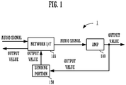
- FIG. 1 is a block diagram showing a configuration of an audio device 1 according to a preferred embodiment of the present invention.
- FIG. 2 is a flow chart showing an operation of the audio device 1.
- FIG. 3 is a block diagram showing a configuration of an audio system 100 including the audio device 1 and a mixer 11 connected to the audio device 1.
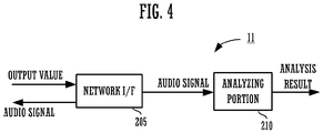
- FIG. 4 is a block diagram showing a configuration of a mixer 11.
- FIG. 5 is a flow chart showing an operation of the mixer 11.
- the audio device 1 includes a network interface (I/F) 103, an amplifier 109, and a sending portion 150.
- the network I/F 103 receives an audio signal from an external device (a mixer 11, for example) through a network (S11).
- the network I/F 103 inputs the received audio signal to the amplifier 109.
- the audio device 1 includes a D/A converting device that converts a digital audio signal into an analog audio signal.
- the audio device 1 may include a signal processing portion (DSP: Digital Signal Processor) that processes the audio signal that the network I/F 103 has received.
- DSP Digital Signal Processor
- the amplifier 109 amplifies and outputs the inputted analog audio signal (S12).
- the analog audio signal is inputted to a not-shown speaker, and is outputted as a sound.
- the sending portion 150 obtains an output value of the amplifier 109 (S13).
- the sending portion 150 for example, obtains a current value or a voltage value as an example of the output value of the amplifier 109 through a current sensor or a voltage sensor provided in the amplifier 109.
- the sending portion 150 sends the obtained output value of the amplifier 109 through the network I/F 103 (S14). For example, the sending portion 150 sends the output value to the mixer 11 connected through the network.
- the mixer 11, as shown in FIG. 4 includes a network I/F 205 and an analyzing portion 210.
- the network I/F 205 receives the output value (S21).
- the network I/F 205 corresponds to a receiving portion.
- the analyzing portion 210 analyzes the received output value (S22).
- the mixer 11 predicts whether or not there is a possibility that a problem may occur in the audio device 1, based on an analysis result of the analyzing portion 210. For example, in a case in which a voltage value shows an unusually high value or a current value shows an unusually high value, there is a possibility that such a problem that makes a sound to stop in the audio device 1 may occur.
- a preferred embodiment of the present invention makes it possible to check information to predict a problem of the audio device 1 from outside (the mixer 11, for example) of the audio device 1.
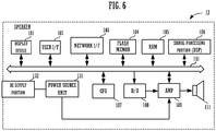
- FIG. 6 is a block diagram showing a configuration of a speaker 13.
- the speaker 13 is one of the specific examples of the audio device 1.
- the speaker 13 includes a display device 101, a user interface (I/F) 102, a network interface (I/F) 103, a flash memory 104, a RAM 105, a signal processing portion 106, a CPU 107, a D/A converter 108, an amplifier 109, a speaker unit 111, a power source unit 131, and an AC supply portion 132.
- the display device 101, user I/F 102, the network I/F 103, the flash memory 104, the RAM 105, the signal processing portion 106, the CPU 107, the D/A converter 108, the amplifier 109, and the signal processing portion 106 are connected to a bus 151.
- the speaker unit 111 is connected to the amplifier 109.
- the power source unit 131 supplies electric power (direct-current power) to drive the amplifier 109. It is to be noted that the power source unit 131 may supply power to each component of the speaker 13. For example, the power source unit 131 may supply power to the CPU 107 to drive.
- the AC supply portion 132 is a power supply portion that supplies alternating-current power to the power source unit 131.
- the AC supply portion 132 is connected to an AC power source for equipment, a power source car, or the like.
- the AC supply portion 132 receives alternating-current power from the AC power source for equipment, a power source car, or the like, and supplies the alternating-current power to the power source unit 131.
- the display device 101 includes an LCD (a Liquid Crystal Display) or an OLED (an Organic Light-Emitting Diode), for example, and displays various types of information.
- the user I/F 102 includes a switch, a knob, or a touch panel, and receives an operation of a user. In a case in which the user I/F 102 is a touch panel, the user I/F 102 configures a GUI (used below as an abbreviation for Graphical User Interface) together with the display device 101.
- a GUI used below as an abbreviation for Graphical User Interface
- the CPU 107 reads a program stored in the flash memory 104 being a storage medium to the RAM 105, and implements a predetermined function. For example, the CPU 107 displays an image for receiving an operation from the user on the display device 101, and, by receiving an operation such as a selection operation of the image from the user I/F 102, implements a GUI.
- the program that the CPU 107 reads does not need to be stored in the flash memory 104 in the own device.
- the program may be stored in a storage medium of an external device such as a server.
- the CPU 107 may read the program each time from the server to the RAM 105 and execute the program.
- the network I/F 103 receives an audio signal from an external device (the mixer 11, for example) through the network (the same operation as S11 in FIG. 2 ).
- the signal processing portion 106 is composed of a DSP for performing various types of signal processing.
- the signal processing portion 106 performs signal processing such as mixing, equalizing, or compressing, on the audio signal inputted through the network I/F 103.
- the signal processing portion 106 outputs the audio signal on which the signal processing has been performed, to the D/A converter 108.
- the D/A converter 108 converts the inputted audio signal into an analog audio signal.
- the amplifier 109 amplifies and outputs the analog audio signal (the same operation as S12 in FIG. 2 ).
- the analog audio signal is inputted to a speaker unit 111, and is outputted as a sound.
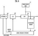
- FIG. 7 is a block diagram showing a more detailed configuration of the amplifier 109.
- the amplifier 109 includes an amplifying element 90 and a current-voltage (VI) detection circuit 91.
- the amplifying element 90 is connected to the power source unit 131.
- the amplifying element 90 by receiving power supply from the power source unit 131, amplifies the analog audio signal outputted from the D/A converter 108 and outputs.
- the VI detection circuit 91 is connected to the subsequent stage of the amplifying element 90, and detects a current value and a voltage value as an example of an output value of the amplifying element 90.
- the signal processing portion 106 obtains a current value and a voltage value from the VI detection circuit 91 (the same operation as S13 in FIG. 2 ).
- the signal processing portion 106 sends the obtained output value through the network I/F 103 (the same operation as S14 in FIG. 2 ).
- the signal processing portion 106 configures the sending portion 150 shown in FIG. 1 by obtaining the output value of the amplifier 109 and sending the output value through the network I/F 103.
- the DSP that receives through the network I/F 103 and processes an audio signal configures the sending portion 150. Therefore, the audio device 1 does not need to separately include new hardware to send the output value of the amplifier 109.
- the sending portion 150 may be configured by an operation of software that the CPU 107 reads. In this case as well, the audio device 1, without having to separately include new hardware to send an output value, is able to send the output value of the amplifier 109.
- FIG. 8 is a block diagram showing a detailed configuration of an amplifier 109 according to a first modification.
- the amplifier 109 according to the first modification includes a VI detection circuit 901 in place of the VI detection circuit 91.
- Other configurations are the same as the configurations of the block diagram shown in FIG. 7 .
- the VI detection circuit 901 is connected between the power source unit 131 and the amplifier 109.
- the VI detection circuit 901 detects a value (a current value and a voltage value) of direct-current power that the power source unit 131 supplies to the amplifier 109.
- the signal processing portion 106 obtains the current value and voltage value of the power source unit 131 from the VI detection circuit 901.
- the signal processing portion 106 sends the obtained current value and voltage value of the power source unit 131, through the network I/F 103. In other words, in this example, the signal processing portion 106 obtains the current value and voltage value from the power source unit 131, and sends through the network I/F 103.
- the analyzing portion 210 is able to predict whether or not there is a possibility that a problem resulting from the direct-current power that the power source unit 131 supplies may occur. For example, when a problem occurs in various types of components of the power source unit 131, a voltage value may decrease or a current value may decrease. Accordingly, in a case in which a voltage value of the power source unit 131 is an unusually low value or a current value is an unusually low value, there is a possibility that such a problem that makes a sound to stop in the audio device 1 may occur.
- the first modification checks a state of the direct-current power of the power source unit 131 from the outside (the mixer 11, for example) of the audio device 1, as information to predict a problem of the audio device 1.
- FIG. 9 is a block diagram showing a detailed configuration of the speaker 13 according to the second modification.
- the speaker 13 according to the second modification includes a VI detection circuit 902.
- the VI detection circuit 902 is connected between the AC supply portion 132 and the power source unit 131.
- the VI detection circuit 902 detects a value (a current value and a voltage value) of alternating-current power that the AC supply portion 132 supplies to the power source unit 131.
- the signal processing portion 106 obtains the current value and voltage value of the AC supply portion 132 from the VI detection circuit 902.
- the signal processing portion 106 sends the obtained current value and voltage value of the AC supply portion 132, through the network I/F 103.
- the signal processing portion 106 obtains the current value and voltage value of the alternating-current power that the AC supply portion 132 outputs, and sends through the network I/F 103.
- the analyzing portion 210 is able to predict whether or not there is a possibility that a problem resulting from the alternating-current power of the AC supply portion 132 may occur. For example, in a case in which voltage of a power source on an equipment side unusually decreases, there is a possibility that such a problem that makes a sound to stop in the audio device 1 may occur.
- the second modification checks a state of the alternating-current power of the AC supply portion 132 from the outside (the mixer 11, for example) of the audio device 1, as information to predict a problem of the audio device 1.
- FIG. 7 , FIG. 8 , and FIG. 9 are able to be implemented independently, the configuration shown in FIG. 7 , FIG. 8 , and FIG. 9 is also able to be combined.
- FIG. 10 is a block diagram showing a detailed configuration of an amplifier 109 according to a third modification.
- the signal processing portion 106 includes an analyzing portion 110A.
- Other configurations are the same as the configurations of the block diagram shown in FIG. 7 .
- the signal processing portion 106 implements the function of the analyzing portion 110A in the example of FIG. 10
- different hardware may configure the analyzing portion 110A.
- the CPU 107 may implement the function of the analyzing portion 110A by software.
- the analyzing portion 110A analyzes the current value and voltage value of the amplifier 109 that have been detected in the VI detection circuit 91.
- the analyzing portion 110A calculates frequency characteristics of impedance as an example of analysis.
- the analyzing portion 110A converts a signal with a time axis of the impedance calculated from the current value and the voltage value into a signal with a frequency axis by the FFT (fast Fourier transform: Fast Fourier Transform).
- the analyzing portion 110A outputs the frequency characteristics of the impedance.
- An analysis result as shown in FIG. 10 , is outputted to an external device through the network I/F 103 or is displayed on the display device 101 by the CPU 107.
- FIG. 11 is a diagram showing the frequency characteristics of impedance.
- the horizontal axis of a graph indicates frequency (Hz) and the vertical axis indicates impedance ( ⁇ ).
- a resonance point occurs in the impedance due to the electric characteristics of each component, the mechanical characteristics of components (a speaker cone and an enclosure, for example) of a speaker unit, or the like.
- a resonance point is present near 100 Hz.
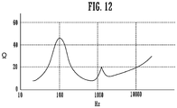
- the impedance of the amplifier 109 may change rapidly in a short time. For example, as shown in FIG. 12 , when a frequency (a singular point) with unusually high impedance is shown, a current does not flow and the amplifier 109 is brought into a state of being unable to damp a speaker. In addition, when a frequency (a singular point) with unusually low impedance is shown, a speaker cone instantly reaches the maximum amplitude, which brings the speaker cone into a state of being unable to vibrate. When such states continue, there is a possibility that a problem may occur in the amplifier 109 or the speaker unit 111, and thus a sound may stop.
- the audio device 1 calculates the frequency characteristics of impedance, and outputs (or displays in the display device 101) the calculated frequency characteristics to the outside as an analysis result.
- a user can predict in advance whether or not such a problem that makes a sound to stops occurs by looking at the frequency characteristics of impedance.
- the CPU 107 in a case in which the above singular point occurs, performs alarm display in the display device 101, or the like, so that the user can predict in advance whether or not a problem of a possibility that a sound may stop occurs.
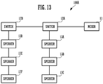
- FIG. 13 is a block diagram showing a configuration of an audio system 100A.
- the audio system 100A includes a mixer 11, a plurality of switches (a switch 12A, a switch 12B), and a plurality of speakers (a speaker 13A to a speaker 13F).
- Each device is connected through a network cable.
- the mixer 11 is connected to the switch 12A.
- the switch 12A is connected to the switch 12B and the speaker 13A.
- the switch 12B is connected to the switch 12A and the speaker 13D.
- the speaker 13A, the speaker 13B, and the speaker 13C are connected to the switch 12A in a daisy chain.
- the speaker 13D, the speaker 13E, and the speaker 13F are also connected to the switch 12B in a daisy chain.
- the connection between devices is not limited to the preferred embodiment shown in FIG. 13 .
- each device does not need to be connected in a network, and may be connected with a communication line such as a USB cable, an HDMI (registered trademark), or a MIDI, for example, or may be connected with a digital audio cable.
- the mixer 11 is an example of a server.
- the mixer 11 receives an input of an audio signal from other devices connected in the network, or outputs an audio signal to other devices.
- the speaker 13A to the speaker 13F are examples of an audio device, and have the same configuration and function as the speaker 13.
- the server is not limited to the mixer 11.
- an information processing device such as a personal computer is also an example of the server.
- a system DAW: Digital Audio Workstation
- DAW Digital Audio Workstation
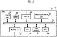
- FIG. 14 is a block diagram showing a configuration of the mixer 11.
- the mixer 11 includes a display device 201, a user I/F 202, an audio I/O (Input/Output) 203, a signal processing portion (DSP) 204, a network I/F 205, a CPU 206, a flash memory 207, and a RAM 208. Such components are connected through a bus 271.
- DSP signal processing portion
- the CPU 206 is a control portion that controls an operation of the mixer 11.
- the CPU 206 performs various types of operations by reading a predetermined program stored in the flash memory 207 being a storage medium to the RAM 208 and executing the program. For example, the CPU 206 receives a current value and voltage value of each amplifier from the speaker 13A to the speaker 13F through the network I/F 205.
- the program that the CPU 206 reads does not also need to be stored in the flash memory 207 in the own device.
- the program may be stored in a storage medium of an external device such as a server.
- the CPU 206 may read the program each time from the server to the RAM 208 and execute the program.
- the signal processing portion 204 is composed of a DSP configured to perform various types of signal processing.
- the signal processing portion 204 performs signal processing such as mixing, equalizing, or compressing, on an audio signal inputted through the audio I/O 203 or the network I/F 205.
- the signal processing portion 204 outputs the audio signal on which the signal processing has been performed, to another device such as the speaker 13A, through the audio I/O 203 or the network I/F 205.
- the signal processing portion 204 receives an input of the current value and voltage value of each amplifier from the CPU 206.
- the signal processing portion 204 configures an analyzing portion 210.
- the analyzing portion 210 of the signal processing portion 204 analyzes an output value of each amplifier (the current value and voltage value of the amplifier 109) from the speaker 13A to the speaker 13F.
- the analyzing portion 210 of the signal processing portion 204 also calculates the frequency characteristics of impedance, for example.
- the signal processing portion 204 has a higher performance than the signal processing portion 106 of the speaker 13A to the speaker 13F, and has a high analysis function.
- the signal processing portion 204 is able to calculate the frequency characteristics of impedance with higher resolution than the signal processing portion 106 of the speaker 13A to the speaker 13F. As a result, the signal processing portion 204 is able to obtain a singular point that may lead to a problem, with high accuracy.
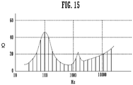
- FIG. 15 is a diagram showing the frequency characteristics of impedance calculated by the signal processing portion 106
- FIG. 16 is a diagram showing the frequency characteristics of impedance calculated by the signal processing portion 204.
- the frequency characteristics of the impedance that the signal processing portion 106 and the signal processing portion 204 calculate are digital signals, and thus are discrete values.
- the number of the discrete value, that is, resolution depends on the number of taps of a digital filter implemented by the DSP, in other words, depends on a DSP resource.
- the signal processing portion 204 of the mixer 11 is implemented from high-performance and multiple DSPs in order to process audio signals of multiple channels.
- the resolution of the frequency characteristics of the impedance that the signal processing portion 106 calculates becomes lower than the resolution of the frequency characteristics of the impedance that the signal processing portion 204 of the mixer 11 calculates. Therefore, there is a possibility that, in the frequency characteristics of the impedance that the signal processing portion 106 has calculated, a resonant frequency that has a steep peak characteristic (a high Q value) may be unable to be extracted.
- the frequency characteristics of the impedance that the signal processing portion 204 has calculated have high resolution, so that a resonant frequency that has a steep peak characteristic is also able to be extracted accurately.
- the mixer 11 is able to receive an output value of an amplifier from each speaker and conduct highly accurate analysis to the extent that is unable to be calculated in each speaker.
- the mixer 11 conducts highly accurate analysis, so that a user can predict in advance a possibility that a problem may occur.
- the user can list analysis results of a plurality of speakers.
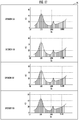
- the mixer 11, as shown in FIG. 17 displays the frequency characteristics of the impedance of the plurality of speakers of the speaker 13A, the speaker 13B, the speaker 13C, and the speaker 13D in the display device 201 of the mixer 11.
- the user can easily specify a speaker that may cause a problem, among the plurality of installed speakers. Therefore, even when the number of installed speakers is increased, the user can easily reset which audio signal to be sent to which speaker and what type of signal processing to be performed. For example, the user, when determining that a possibility that a problem may occur in a certain speaker (a first speaker) is high, changes the setting of the mixer 11. For example, the user, by using the bus set to the first speaker for a different speaker (a second speaker), can cause an audio signal of the bus to be outputted from the second speaker.
- the user looks at the display of the display device 201 and can determine whether a possibility that a problem may occur only in a specific speaker is high or whether a possibility that a problem may occur in a plurality of speakers in conjunction with one another is high. For example, as shown in FIG. 17 , in a case in which a similar singular point is generated in the plurality of speakers of the speaker 13A, the speaker 13B, the speaker 13C, and the speaker 13D, the user of the mixer 11 can determine that the problem is not an individual problem that occurs in each speaker but is a problem that occurs in a plurality of devices in conjunction with one another.
- a cause common to a plurality of devices such as a problem due to the power source on the equipment side, a problem of the space in which the speaker is installed, or a problem of equipment (a rack for installing in the form of an array, for example) to install a plurality of speakers, is able to be narrowed down.
- analysis is not limited to calculation of the frequency characteristics of impedance.
- an average current value and an average voltage value may be obtained, or an instantaneous value and an average value may be compared.
- the output value of the amplifier 109 is an alternating-current signal, so that any method is able to be applied to a method to be used for analysis of an alternating-current signal.
- the output value (a voltage value and a current value) of the amplifier is an analog audio signal itself, so that analysis as a sound is possible.
- the user can determine that a possibility that a problem may occur is high, for example, when a noise sound is loud, by listening to the output value (a voltage value and a current value) of the amplifier as a sound.
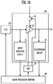
- FIG. 18 is a block diagram showing a configuration of the amplifier 109 that shuts off a power source at the time of silence, for reduction in power consumption.
- the amplifier 109 includes an amplifying element 90, a VI detection circuit 91, an input detection circuit 95, and a switch 50.
- the input detection circuit 95 is connected to the preceding stage of the amplifying element 90, and detects the level of an audio signal to be inputted to the amplifying element 90.
- the CPU 107 determines whether or not an audio signal is inputted based on the detection result of the input detection circuit 95. For example, the CPU 107 determines that an audio signal is being inputted, in a case in which the level of the audio signal detected in the input detection circuit 95 is not less than a predetermined value. The CPU 107 determines that an audio signal is not being inputted, in a case in which the level of the audio signal is less than a predetermined value. The CPU 107, in a case of determining that an audio signal is not being inputted, turns off the switch 50 and shuts off the power source of the amplifying element 90. As a result, the CPU 107 reduces wasted power consumption.
- the CPU 107 even when turning off the switch 50, turns on the switch 50 in a case in which the voltage value detected in the VI detection circuit 91 exceeds a predetermined threshold value.
- the cone of a speaker unit vibrates freely. Accordingly, the cone of the speaker unit may vibrate under the influence of a sound emitted from other speakers.
- the amplifying element 90 may be damaged due to a counter electromotive force.
- PA Public Address
- the CPU 107 even when shutting off the power source of the amplifying element 90, turns on the switch 50 and turns on a power source, in a case in which the voltage value detected in the VI detection circuit 91 exceeds a predetermined threshold value.
- a power source is supplied to the amplifying element 90, an operation of the cone of a speaker unit is controlled by electric power (power of an output signal) of the power source.
- the amplifier 109 prevents the amplifying element 90 from being damaged due to the counter electromotive force generated when the cone of a speaker unit vibrates.
- the mixer 11 sends instructions to turn on a power source, to a speaker of which the counter electromotive force exceeds a predetermined value. In this manner, the output value of the amplifier is outputted to outside, which enables a user to monitor a state of each speaker from a server.
- the audio device is able to prevent a problem from occurring beforehand while reducing power consumption.
Landscapes
- Engineering & Computer Science (AREA)
- Physics & Mathematics (AREA)
- Acoustics & Sound (AREA)
- Signal Processing (AREA)
- Power Engineering (AREA)
- Health & Medical Sciences (AREA)
- General Health & Medical Sciences (AREA)
- Otolaryngology (AREA)
- Microelectronics & Electronic Packaging (AREA)
- Multimedia (AREA)
- Circuit For Audible Band Transducer (AREA)
- Amplifiers (AREA)
Abstract
Description
- A preferred embodiment of the present invention relates to an audio device that inputs or outputs an audio signal, a server, an audio system, a method of controlling such an audio device, and a program.
-
Patent Literature 1 discloses that a signal of a DSP (Digital Signal Processor) 6 is outputted to anemulator 10 to cause theemulator 10 to perform debug of the DSP 6. - Patent Literature 1: Japanese Examined Patent Application Publication No.
H07-111686 - It is important that an audio device does not stop a sound while in use. In other words, it is important that an audio device predicts whether or not such a problem that a sound stops occurs.
Patent Literature 1 does not disclose that occurrence of a problem is predicted. - A preferred embodiment of the present invention is directed to provide an audio device, a server, an audio system, a method of controlling an audio device, and a program that are able to check information to predict a problem of the audio device, from outside of the audio device.
- An audio device includes a network interface, an amplifier that amplifies an audio signal received through the network interface, and a sending portion that obtains an output value of the amplifier and sends the output value through the network interface.
- A preferred embodiment of the present invention is able to check information to predict a problem of an audio device from outside of the audio device.
-
-
FIG. 1 is a block diagram showing a configuration of anaudio device 1. -
FIG. 2 is a flow chart showing an operation of theaudio device 1. -
FIG. 3 is a block diagram showing a configuration of anaudio system 100 including theaudio device 1 and amixer 11 connected to theaudio device 1. -
FIG. 4 is a block diagram showing a configuration of themixer 11. -
FIG. 5 is a flow chart showing an operation of themixer 11. -
FIG. 6 is a block diagram showing a configuration of aspeaker 13. -
FIG. 7 is a block diagram showing a more detailed configuration of anamplifier 109. -
FIG. 8 is a block diagram showing a detailed configuration of anamplifier 109 according to a first modification. -
FIG. 9 is a block diagram showing a detailed configuration of anamplifier 109 according to a second modification. -
FIG. 10 is a block diagram showing a detailed configuration of anamplifier 109 according to a third modification. -
FIG. 11 is a diagram showing frequency characteristics of impedance. -
FIG. 12 is a diagram showing frequency characteristics of impedance. -
FIG. 13 is a block diagram showing a configuration of an audio system. -
FIG. 14 is a block diagram showing a configuration of themixer 11. -
FIG. 15 is a diagram showing frequency characteristics of impedance calculated by asignal processing portion 106. -
FIG. 16 is a diagram showing frequency characteristics of impedance calculated by asignal processing portion 204. -
FIG. 17 is a diagram showing a display example in adisplay device 201 of themixer 11. -
FIG. 18 is a block diagram showing a configuration of anamplifier 109 that shuts off a power source at the time of silence. -
FIG. 1 is a block diagram showing a configuration of anaudio device 1 according to a preferred embodiment of the present invention.FIG. 2 is a flow chart showing an operation of theaudio device 1.FIG. 3 is a block diagram showing a configuration of anaudio system 100 including theaudio device 1 and amixer 11 connected to theaudio device 1.FIG. 4 is a block diagram showing a configuration of amixer 11.FIG. 5 is a flow chart showing an operation of themixer 11. - The
audio device 1 includes a network interface (I/F) 103, anamplifier 109, and asending portion 150. The network I/F 103 receives an audio signal from an external device (amixer 11, for example) through a network (S11). The network I/F 103 inputs the received audio signal to theamplifier 109. It is to be noted that, although omitted inFIG. 1 , theaudio device 1 includes a D/A converting device that converts a digital audio signal into an analog audio signal. - It is to be noted that the
audio device 1 may include a signal processing portion (DSP: Digital Signal Processor) that processes the audio signal that the network I/F 103 has received. - The
amplifier 109 amplifies and outputs the inputted analog audio signal (S12). The analog audio signal is inputted to a not-shown speaker, and is outputted as a sound. - The
sending portion 150 obtains an output value of the amplifier 109 (S13). Thesending portion 150, for example, obtains a current value or a voltage value as an example of the output value of theamplifier 109 through a current sensor or a voltage sensor provided in theamplifier 109. - The
sending portion 150 sends the obtained output value of theamplifier 109 through the network I/F 103 (S14). For example, thesending portion 150 sends the output value to themixer 11 connected through the network. - The
mixer 11, as shown inFIG. 4 , includes a network I/F 205 and an analyzingportion 210. The network I/F 205 receives the output value (S21). In other words, the network I/F 205 corresponds to a receiving portion. The analyzingportion 210 analyzes the received output value (S22). Themixer 11 predicts whether or not there is a possibility that a problem may occur in theaudio device 1, based on an analysis result of the analyzingportion 210. For example, in a case in which a voltage value shows an unusually high value or a current value shows an unusually high value, there is a possibility that such a problem that makes a sound to stop in theaudio device 1 may occur. - In this manner, a preferred embodiment of the present invention makes it possible to check information to predict a problem of the
audio device 1 from outside (themixer 11, for example) of theaudio device 1. - Next,
FIG. 6 is a block diagram showing a configuration of aspeaker 13. Thespeaker 13 is one of the specific examples of theaudio device 1. - The
speaker 13 includes adisplay device 101, a user interface (I/F) 102, a network interface (I/F) 103, aflash memory 104, aRAM 105, asignal processing portion 106, aCPU 107, a D/A converter 108, anamplifier 109, aspeaker unit 111, apower source unit 131, and anAC supply portion 132. - The
display device 101, user I/F 102, the network I/F 103, theflash memory 104, theRAM 105, thesignal processing portion 106, theCPU 107, the D/A converter 108, theamplifier 109, and thesignal processing portion 106 are connected to abus 151. Thespeaker unit 111 is connected to theamplifier 109. - The
power source unit 131 supplies electric power (direct-current power) to drive theamplifier 109. It is to be noted that thepower source unit 131 may supply power to each component of thespeaker 13. For example, thepower source unit 131 may supply power to theCPU 107 to drive. - The
AC supply portion 132 is a power supply portion that supplies alternating-current power to thepower source unit 131. TheAC supply portion 132 is connected to an AC power source for equipment, a power source car, or the like. TheAC supply portion 132 receives alternating-current power from the AC power source for equipment, a power source car, or the like, and supplies the alternating-current power to thepower source unit 131. - The
display device 101 includes an LCD (a Liquid Crystal Display) or an OLED (an Organic Light-Emitting Diode), for example, and displays various types of information. The user I/F 102 includes a switch, a knob, or a touch panel, and receives an operation of a user. In a case in which the user I/F 102 is a touch panel, the user I/F 102 configures a GUI (used below as an abbreviation for Graphical User Interface) together with thedisplay device 101. - The
CPU 107 reads a program stored in theflash memory 104 being a storage medium to theRAM 105, and implements a predetermined function. For example, theCPU 107 displays an image for receiving an operation from the user on thedisplay device 101, and, by receiving an operation such as a selection operation of the image from the user I/F 102, implements a GUI. - It is to be noted that the program that the
CPU 107 reads does not need to be stored in theflash memory 104 in the own device. For example, the program may be stored in a storage medium of an external device such as a server. In such a case, theCPU 107 may read the program each time from the server to theRAM 105 and execute the program. - The network I/
F 103 receives an audio signal from an external device (themixer 11, for example) through the network (the same operation as S11 inFIG. 2 ). - The
signal processing portion 106 is composed of a DSP for performing various types of signal processing. Thesignal processing portion 106 performs signal processing such as mixing, equalizing, or compressing, on the audio signal inputted through the network I/F 103. Thesignal processing portion 106 outputs the audio signal on which the signal processing has been performed, to the D/A converter 108. - The D/
A converter 108 converts the inputted audio signal into an analog audio signal. Theamplifier 109 amplifies and outputs the analog audio signal (the same operation as S12 inFIG. 2 ). The analog audio signal is inputted to aspeaker unit 111, and is outputted as a sound. -
FIG. 7 is a block diagram showing a more detailed configuration of theamplifier 109. Theamplifier 109 includes an amplifyingelement 90 and a current-voltage (VI)detection circuit 91. The amplifyingelement 90 is connected to thepower source unit 131. The amplifyingelement 90, by receiving power supply from thepower source unit 131, amplifies the analog audio signal outputted from the D/A converter 108 and outputs. - The
VI detection circuit 91 is connected to the subsequent stage of the amplifyingelement 90, and detects a current value and a voltage value as an example of an output value of the amplifyingelement 90. Thesignal processing portion 106 obtains a current value and a voltage value from the VI detection circuit 91 (the same operation as S13 inFIG. 2 ). Thesignal processing portion 106 sends the obtained output value through the network I/F 103 (the same operation as S14 inFIG. 2 ). In other words, in this example, thesignal processing portion 106 configures the sendingportion 150 shown inFIG. 1 by obtaining the output value of theamplifier 109 and sending the output value through the network I/F 103. - In this example, the DSP that receives through the network I/
F 103 and processes an audio signal configures the sendingportion 150. Therefore, theaudio device 1 does not need to separately include new hardware to send the output value of theamplifier 109. In addition, the sendingportion 150 may be configured by an operation of software that theCPU 107 reads. In this case as well, theaudio device 1, without having to separately include new hardware to send an output value, is able to send the output value of theamplifier 109. -
FIG. 8 is a block diagram showing a detailed configuration of anamplifier 109 according to a first modification. Theamplifier 109 according to the first modification includes aVI detection circuit 901 in place of theVI detection circuit 91. Other configurations are the same as the configurations of the block diagram shown inFIG. 7 . - The
VI detection circuit 901 is connected between thepower source unit 131 and theamplifier 109. TheVI detection circuit 901 detects a value (a current value and a voltage value) of direct-current power that thepower source unit 131 supplies to theamplifier 109. Thesignal processing portion 106 obtains the current value and voltage value of thepower source unit 131 from theVI detection circuit 901. Thesignal processing portion 106 sends the obtained current value and voltage value of thepower source unit 131, through the network I/F 103. In other words, in this example, thesignal processing portion 106 obtains the current value and voltage value from thepower source unit 131, and sends through the network I/F 103. - As a result, the analyzing
portion 210 is able to predict whether or not there is a possibility that a problem resulting from the direct-current power that thepower source unit 131 supplies may occur. For example, when a problem occurs in various types of components of thepower source unit 131, a voltage value may decrease or a current value may decrease. Accordingly, in a case in which a voltage value of thepower source unit 131 is an unusually low value or a current value is an unusually low value, there is a possibility that such a problem that makes a sound to stop in theaudio device 1 may occur. - Accordingly, the first modification checks a state of the direct-current power of the
power source unit 131 from the outside (themixer 11, for example) of theaudio device 1, as information to predict a problem of theaudio device 1. -
FIG. 9 is a block diagram showing a detailed configuration of thespeaker 13 according to the second modification. Thespeaker 13 according to the second modification includes aVI detection circuit 902. - The
VI detection circuit 902 is connected between theAC supply portion 132 and thepower source unit 131. TheVI detection circuit 902 detects a value (a current value and a voltage value) of alternating-current power that theAC supply portion 132 supplies to thepower source unit 131. Thesignal processing portion 106 obtains the current value and voltage value of theAC supply portion 132 from theVI detection circuit 902. Thesignal processing portion 106 sends the obtained current value and voltage value of theAC supply portion 132, through the network I/F 103. In other words, in this example, thesignal processing portion 106 obtains the current value and voltage value of the alternating-current power that theAC supply portion 132 outputs, and sends through the network I/F 103. - As a result, the analyzing
portion 210 is able to predict whether or not there is a possibility that a problem resulting from the alternating-current power of theAC supply portion 132 may occur. For example, in a case in which voltage of a power source on an equipment side unusually decreases, there is a possibility that such a problem that makes a sound to stop in theaudio device 1 may occur. - Accordingly, the second modification checks a state of the alternating-current power of the
AC supply portion 132 from the outside (themixer 11, for example) of theaudio device 1, as information to predict a problem of theaudio device 1. - It is to be noted that, although the configuration shown in each of
FIG. 7 ,FIG. 8 , andFIG. 9 is able to be implemented independently, the configuration shown inFIG. 7 ,FIG. 8 , andFIG. 9 is also able to be combined. - Next,
FIG. 10 is a block diagram showing a detailed configuration of anamplifier 109 according to a third modification. In theamplifier 109 according to the third modification, thesignal processing portion 106 includes an analyzingportion 110A. Other configurations are the same as the configurations of the block diagram shown inFIG. 7 . - It is to be noted that, although the
signal processing portion 106 implements the function of the analyzingportion 110A in the example ofFIG. 10 , different hardware may configure the analyzingportion 110A. In addition, theCPU 107 may implement the function of the analyzingportion 110A by software. - The analyzing
portion 110A analyzes the current value and voltage value of theamplifier 109 that have been detected in theVI detection circuit 91. The analyzingportion 110A, for example, calculates frequency characteristics of impedance as an example of analysis. The analyzingportion 110A converts a signal with a time axis of the impedance calculated from the current value and the voltage value into a signal with a frequency axis by the FFT (fast Fourier transform: Fast Fourier Transform). The analyzingportion 110A outputs the frequency characteristics of the impedance. An analysis result, as shown inFIG. 10 , is outputted to an external device through the network I/F 103 or is displayed on thedisplay device 101 by theCPU 107. -
FIG. 11 is a diagram showing the frequency characteristics of impedance. The horizontal axis of a graph indicates frequency (Hz) and the vertical axis indicates impedance (Ω). In general amplifiers including theamplifier 109, a resonance point occurs in the impedance due to the electric characteristics of each component, the mechanical characteristics of components (a speaker cone and an enclosure, for example) of a speaker unit, or the like. In the example ofFIG. 10 , a resonance point is present near 100 Hz. - Then, when a problem occurs in the
speaker unit 111, there is a possibility that the impedance of theamplifier 109 may change rapidly in a short time. For example, as shown inFIG. 12 , when a frequency (a singular point) with unusually high impedance is shown, a current does not flow and theamplifier 109 is brought into a state of being unable to damp a speaker. In addition, when a frequency (a singular point) with unusually low impedance is shown, a speaker cone instantly reaches the maximum amplitude, which brings the speaker cone into a state of being unable to vibrate. When such states continue, there is a possibility that a problem may occur in theamplifier 109 or thespeaker unit 111, and thus a sound may stop. - Therefore, the
audio device 1 calculates the frequency characteristics of impedance, and outputs (or displays in the display device 101) the calculated frequency characteristics to the outside as an analysis result. As a result, a user can predict in advance whether or not such a problem that makes a sound to stops occurs by looking at the frequency characteristics of impedance. Alternatively, theCPU 107, in a case in which the above singular point occurs, performs alarm display in thedisplay device 101, or the like, so that the user can predict in advance whether or not a problem of a possibility that a sound may stop occurs. - Next,
FIG. 13 is a block diagram showing a configuration of anaudio system 100A. Theaudio system 100A includes amixer 11, a plurality of switches (aswitch 12A, aswitch 12B), and a plurality of speakers (aspeaker 13A to aspeaker 13F). - Each device is connected through a network cable. For example, the
mixer 11 is connected to theswitch 12A. Theswitch 12A is connected to theswitch 12B and thespeaker 13A. Theswitch 12B is connected to theswitch 12A and thespeaker 13D. Thespeaker 13A, thespeaker 13B, and thespeaker 13C are connected to theswitch 12A in a daisy chain. In addition, thespeaker 13D, thespeaker 13E, and thespeaker 13F are also connected to theswitch 12B in a daisy chain. However, the connection between devices is not limited to the preferred embodiment shown inFIG. 13 . In addition, each device does not need to be connected in a network, and may be connected with a communication line such as a USB cable, an HDMI (registered trademark), or a MIDI, for example, or may be connected with a digital audio cable. - The
mixer 11 is an example of a server. Themixer 11 receives an input of an audio signal from other devices connected in the network, or outputs an audio signal to other devices. Thespeaker 13A to thespeaker 13F are examples of an audio device, and have the same configuration and function as thespeaker 13. It is to be noted that the server is not limited to themixer 11. For example, an information processing device such as a personal computer is also an example of the server. In addition, a system (DAW: Digital Audio Workstation) including hardware or software to perform work including recording, editing, mixing, or the like of audio is also an example of the server. -
FIG. 14 is a block diagram showing a configuration of themixer 11. Themixer 11 includes adisplay device 201, a user I/F 202, an audio I/O (Input/Output) 203, a signal processing portion (DSP) 204, a network I/F 205, aCPU 206, aflash memory 207, and aRAM 208. Such components are connected through abus 271. - The
CPU 206 is a control portion that controls an operation of themixer 11. TheCPU 206 performs various types of operations by reading a predetermined program stored in theflash memory 207 being a storage medium to theRAM 208 and executing the program. For example, theCPU 206 receives a current value and voltage value of each amplifier from thespeaker 13A to thespeaker 13F through the network I/F 205. - It is to be noted that the program that the
CPU 206 reads does not also need to be stored in theflash memory 207 in the own device. For example, the program may be stored in a storage medium of an external device such as a server. In such a case, theCPU 206 may read the program each time from the server to theRAM 208 and execute the program. - The
signal processing portion 204 is composed of a DSP configured to perform various types of signal processing. Thesignal processing portion 204 performs signal processing such as mixing, equalizing, or compressing, on an audio signal inputted through the audio I/O 203 or the network I/F 205. Thesignal processing portion 204 outputs the audio signal on which the signal processing has been performed, to another device such as thespeaker 13A, through the audio I/O 203 or the network I/F 205. - In addition, the
signal processing portion 204 receives an input of the current value and voltage value of each amplifier from theCPU 206. Thesignal processing portion 204 configures an analyzingportion 210. The analyzingportion 210 of thesignal processing portion 204 analyzes an output value of each amplifier (the current value and voltage value of the amplifier 109) from thespeaker 13A to thespeaker 13F. The analyzingportion 210 of thesignal processing portion 204 also calculates the frequency characteristics of impedance, for example. However, thesignal processing portion 204 has a higher performance than thesignal processing portion 106 of thespeaker 13A to thespeaker 13F, and has a high analysis function. Therefore, thesignal processing portion 204 is able to calculate the frequency characteristics of impedance with higher resolution than thesignal processing portion 106 of thespeaker 13A to thespeaker 13F. As a result, thesignal processing portion 204 is able to obtain a singular point that may lead to a problem, with high accuracy. -
FIG. 15 is a diagram showing the frequency characteristics of impedance calculated by thesignal processing portion 106, andFIG. 16 is a diagram showing the frequency characteristics of impedance calculated by thesignal processing portion 204. - As shown in
FIG. 15 andFIG. 16 , the frequency characteristics of the impedance that thesignal processing portion 106 and thesignal processing portion 204 calculate are digital signals, and thus are discrete values. The number of the discrete value, that is, resolution depends on the number of taps of a digital filter implemented by the DSP, in other words, depends on a DSP resource. Thesignal processing portion 204 of themixer 11 is implemented from high-performance and multiple DSPs in order to process audio signals of multiple channels. On the one hand, thesignal processing portion 106 provided in thespeaker 13, in order to process an audio signal for one channel or several channels sent from themixer 11, uses a DSP of which the performance is relatively lower than the performance of the DSP of thesignal processing portion 204 of themixer 11. Therefore, as shown inFIG. 15 andFIG. 16 , the resolution of the frequency characteristics of the impedance that thesignal processing portion 106 calculates becomes lower than the resolution of the frequency characteristics of the impedance that thesignal processing portion 204 of themixer 11 calculates. Therefore, there is a possibility that, in the frequency characteristics of the impedance that thesignal processing portion 106 has calculated, a resonant frequency that has a steep peak characteristic (a high Q value) may be unable to be extracted. On the other hand, as shown inFIG. 16 , the frequency characteristics of the impedance that thesignal processing portion 204 has calculated have high resolution, so that a resonant frequency that has a steep peak characteristic is also able to be extracted accurately. - In this manner, the
mixer 11 is able to receive an output value of an amplifier from each speaker and conduct highly accurate analysis to the extent that is unable to be calculated in each speaker. In particular, in a case in which impedance changes rapidly in a short time, there is a possibility that a steep characteristic to the extent that is unable to be extracted in each speaker alone may occur. However, themixer 11 conducts highly accurate analysis, so that a user can predict in advance a possibility that a problem may occur. - In addition, in the
mixer 11, the user can list analysis results of a plurality of speakers. For example, themixer 11, as shown inFIG. 17 , displays the frequency characteristics of the impedance of the plurality of speakers of thespeaker 13A, thespeaker 13B, thespeaker 13C, and thespeaker 13D in thedisplay device 201 of themixer 11. - In such a case, the user can easily specify a speaker that may cause a problem, among the plurality of installed speakers. Therefore, even when the number of installed speakers is increased, the user can easily reset which audio signal to be sent to which speaker and what type of signal processing to be performed. For example, the user, when determining that a possibility that a problem may occur in a certain speaker (a first speaker) is high, changes the setting of the
mixer 11. For example, the user, by using the bus set to the first speaker for a different speaker (a second speaker), can cause an audio signal of the bus to be outputted from the second speaker. - In addition, the user looks at the display of the
display device 201 and can determine whether a possibility that a problem may occur only in a specific speaker is high or whether a possibility that a problem may occur in a plurality of speakers in conjunction with one another is high. For example, as shown inFIG. 17 , in a case in which a similar singular point is generated in the plurality of speakers of thespeaker 13A, thespeaker 13B, thespeaker 13C, and thespeaker 13D, the user of themixer 11 can determine that the problem is not an individual problem that occurs in each speaker but is a problem that occurs in a plurality of devices in conjunction with one another. Therefore, a cause common to a plurality of devices, such as a problem due to the power source on the equipment side, a problem of the space in which the speaker is installed, or a problem of equipment (a rack for installing in the form of an array, for example) to install a plurality of speakers, is able to be narrowed down. - In addition, as described above, the user of the
mixer 11, in a case of determining that a possibility that a problem may occur in a specific speaker is high, can take appropriate actions such as performing settings to send an audio signal to be sent to the specific speaker to a different speaker. In addition, theCPU 206 of themixer 11, in a case in which an impedance characteristic (a peak with a high Q value) that shows a steeply high value is present in a predetermined frequency band, may perform an operation to send an audio signal to be sent to the speaker, to a different speaker. In such a case, theCPU 206 functions as a control portion that controls a parameter of the audio device, based on an analysis result of the analyzing portion. - It is to be noted that, although the present preferred embodiment describes an example of calculating frequency characteristics of impedance, analysis is not limited to calculation of the frequency characteristics of impedance. For example, an average current value and an average voltage value may be obtained, or an instantaneous value and an average value may be compared. The output value of the
amplifier 109 is an alternating-current signal, so that any method is able to be applied to a method to be used for analysis of an alternating-current signal. - In addition, the output value (a voltage value and a current value) of the amplifier is an analog audio signal itself, so that analysis as a sound is possible. The user can determine that a possibility that a problem may occur is high, for example, when a noise sound is loud, by listening to the output value (a voltage value and a current value) of the amplifier as a sound.
- It is to be noted that the descriptions of the preferred embodiments are illustrative in all points and should not be construed to limit the present invention. The scope of the present invention is defined not by the foregoing preferred embodiments but by the claims for patent. Further, the scope of the present invention is intended to include all modifications within the scopes of the claims for patent and within the meanings and scopes of equivalents.
- For example,
FIG. 18 is a block diagram showing a configuration of theamplifier 109 that shuts off a power source at the time of silence, for reduction in power consumption. InFIG. 18 , theamplifier 109 includes an amplifyingelement 90, aVI detection circuit 91, aninput detection circuit 95, and aswitch 50. - The
input detection circuit 95 is connected to the preceding stage of the amplifyingelement 90, and detects the level of an audio signal to be inputted to the amplifyingelement 90. TheCPU 107 determines whether or not an audio signal is inputted based on the detection result of theinput detection circuit 95. For example, theCPU 107 determines that an audio signal is being inputted, in a case in which the level of the audio signal detected in theinput detection circuit 95 is not less than a predetermined value. TheCPU 107 determines that an audio signal is not being inputted, in a case in which the level of the audio signal is less than a predetermined value. TheCPU 107, in a case of determining that an audio signal is not being inputted, turns off theswitch 50 and shuts off the power source of the amplifyingelement 90. As a result, theCPU 107 reduces wasted power consumption. - On the other hand, the
CPU 107, even when turning off theswitch 50, turns on theswitch 50 in a case in which the voltage value detected in theVI detection circuit 91 exceeds a predetermined threshold value. When the power source of the amplifyingelement 90 is shut off, the cone of a speaker unit vibrates freely. Accordingly, the cone of the speaker unit may vibrate under the influence of a sound emitted from other speakers. When the cone of the speaker unit vibrates, there is a possibility that the amplifyingelement 90 may be damaged due to a counter electromotive force. In particular, in a case of a PA (Public Address) system in a large-scale space, a large number of a plurality of speakers are installed next to each other. In addition, the volume of each speaker becomes very large. Accordingly, vibration between the plurality of speakers significantly affects each other. - Thus, the
CPU 107, even when shutting off the power source of the amplifyingelement 90, turns on theswitch 50 and turns on a power source, in a case in which the voltage value detected in theVI detection circuit 91 exceeds a predetermined threshold value. When a power source is supplied to the amplifyingelement 90, an operation of the cone of a speaker unit is controlled by electric power (power of an output signal) of the power source. As a result, theamplifier 109 prevents the amplifyingelement 90 from being damaged due to the counter electromotive force generated when the cone of a speaker unit vibrates. - Then, as shown in
FIG. 13 , in a case in which an output value of each speaker is sent to themixer 11, the counter electromotive force of each speaker is able to be monitored in themixer 11. In such a case, themixer 11 sends instructions to turn on a power source, to a speaker of which the counter electromotive force exceeds a predetermined value. In this manner, the output value of the amplifier is outputted to outside, which enables a user to monitor a state of each speaker from a server. The audio device is able to prevent a problem from occurring beforehand while reducing power consumption. -
- 11
- mixer
- 12A, 12B
- switch
- 13, 13A, 13B, 13C, 13D, 13E, 13F
- speaker
- 50
- switch
- 90
- amplifying element
- 91
- VI detection circuit
- 95
- input detection circuit
- 100
- audio system
- 101
- display device
- 102
- user I/F
- 103
- network I/F
- 104
- flash memory
- 105
- RAM
- 106
- signal processing portion
- 107
- CPU
- 108
- D/A converter
- 109
- amplifier
- 110A
- analyzing portion
- 111
- speaker unit
- 131
- power source unit
- 132
- AC supply portion
- 150
- sending portion
- 151
- bus
- 201
- display device
- 202
- user I/F
- 203
- audio I/O
- 204
- signal processing portion
- 205
- network I/F
- 206
- CPU
- 207
- flash memory
- 208
- RAM
- 210
- analyzing portion
- 271
- bus
- 901, 902
- VI detection circuit
Claims (15)
- An audio device comprising:a network interface;an amplifier that amplifies an audio signal received through the network interface; anda sending portion that obtains an output value of the amplifier and sends the output value through the network interface.
- The audio device according to claim 1, comprising a signal processing portion that performs signal processing on the audio signal received through the network interface, wherein the signal processing portion configures the sending portion by obtaining the output value, and sending the output value through the network interface.
- The audio device according to claim 1 or 2, comprising a power source unit that supplies power to the amplifier, wherein the sending portion obtains a current value or a voltage value of the power supplied by the power source unit supplies, and sends through the network interface.
- The audio device according to claim 3, comprising a power supply portion that supplies alternating-current power to the power source unit, wherein the sending portion obtains a current value or a voltage value of the alternating-current power that the power supply portion supplies, and sends through the network interface.
- The audio device according to any of claims 1 to 4, further comprising an analyzing portion that analyzes the output value.
- A server comprising:a network interface;a receiving portion that receives an output value of an amplifier of an audio device from the audio device through the network interface; andan analyzing portion that analyzes the output value received by the receiving portion.
- The server according to claim 6, comprising a control portion that controls a parameter of the audio device, based on an analysis result of the analyzing portion.
- The server according to claim 6 or 7, wherein the analyzing portion calculates frequency characteristics of impedance.
- An audio system comprising an audio device and a server, wherein
the audio device includes:a first network interface;an amplifier that amplifies an audio signal received through the first network interface; anda sending portion that obtains an output value of the amplifier and sends the output value through the first network interface, andthe server includes:a second network interface;a receiving portion that receives the output value of the amplifier of the audio device from the audio device through the second network interface; andan analyzing portion that analyzes the output value received by the receiving portion. - A controlling method of an audio device, comprising:amplifying by an amplifier an audio signal received through a network interface;obtaining an output value of the amplifier; andsending the output value through the network interface.
- The controlling method of an audio device according to claim 10, comprising obtaining the output value and sending the output value through the network interface by a signal processing portion that performs signal processing on the audio signal received through the network interface.
- The controlling method of an audio device according to claim 10 or 11, comprising:obtaining a current value or a voltage value of the power supplied by a power source unit, the power source unit supplying power to the amplifier; andsending through the network interface.
- The controlling method of an audio device according to claim 12, comprising:obtaining a current value or a voltage value of a power supply portion that supplies alternating-current power to the power source unit; andsending through the network interface.
- The controlling method of an audio device according to any of claims 10 to 13, comprising analyzing the output value.
- A program to cause an audio device to perform:processing of amplifying by an amplifier an audio signal received through a network interface;processing of obtaining an output value of the amplifier; andprocessing of sending the output value through the network interface.
Applications Claiming Priority (2)
| Application Number | Priority Date | Filing Date | Title |
|---|---|---|---|
| JP2018053821A JP7069910B2 (en) | 2018-03-22 | 2018-03-22 | Audio equipment, servers, audio systems, audio equipment control methods and server control methods |
| PCT/JP2019/008992 WO2019181522A1 (en) | 2018-03-22 | 2019-03-07 | Acoustic apparatus, server, acoustic system, method for controlling acoustic apparatus, and program |
Publications (3)
| Publication Number | Publication Date |
|---|---|
| EP3771097A1 true EP3771097A1 (en) | 2021-01-27 |
| EP3771097A4 EP3771097A4 (en) | 2021-12-22 |
| EP3771097B1 EP3771097B1 (en) | 2026-02-18 |
Family
ID=67986480
Family Applications (1)
| Application Number | Title | Priority Date | Filing Date |
|---|---|---|---|
| EP19770817.5A Active EP3771097B1 (en) | 2018-03-22 | 2019-03-07 | Acoustic apparatus, server, acoustic system, method for controlling acoustic apparatus, and program |
Country Status (5)
| Country | Link |
|---|---|
| US (1) | US11516605B2 (en) |
| EP (1) | EP3771097B1 (en) |
| JP (1) | JP7069910B2 (en) |
| CN (1) | CN111903055B (en) |
| WO (1) | WO2019181522A1 (en) |
Families Citing this family (2)
| Publication number | Priority date | Publication date | Assignee | Title |
|---|---|---|---|---|
| JP7409122B2 (en) * | 2020-01-31 | 2024-01-09 | ヤマハ株式会社 | Management server, sound management method, program, sound client and sound management system |
| JP7409121B2 (en) * | 2020-01-31 | 2024-01-09 | ヤマハ株式会社 | Management server, acoustic check method, program, acoustic client and acoustic check system |
Family Cites Families (17)
| Publication number | Priority date | Publication date | Assignee | Title |
|---|---|---|---|---|
| US5375228A (en) | 1991-02-04 | 1994-12-20 | Analog Devices, Inc. | Real-time signal analysis apparatus and method for digital signal processor emulation |
| JPH07111686A (en) | 1993-10-12 | 1995-04-25 | Matsushita Electric Ind Co Ltd | Operating device |
| JPH11215683A (en) * | 1998-01-28 | 1999-08-06 | Ricoh Co Ltd | Image recording device, image reading device, facsimile device, and copying device |
| JP3621020B2 (en) * | 1999-12-24 | 2005-02-16 | 日本電信電話株式会社 | Music reaction robot and transmitter |
| US7043041B2 (en) * | 2000-10-04 | 2006-05-09 | Sonionmicrotronic Nederland B.V. | Integrated telecoil amplifier with signal processing |
| EP1374394B1 (en) * | 2001-03-26 | 2006-05-31 | Harman International Industries, Incorporated | Digital signal processor enhanced pulse width modulation amplifier |
| ATE543341T1 (en) * | 2003-06-10 | 2012-02-15 | Harman Int Ind | AUDIO AMPLIFIER WITH LOCAL INTERFACE |
| EP2028882B1 (en) | 2007-08-01 | 2018-10-10 | Yamaha Corporation | Remote audio monitoring system for amplifiers in a network |
| JP4341707B2 (en) * | 2007-08-01 | 2009-10-07 | ヤマハ株式会社 | Audio amplifier remote monitoring device and remote monitoring program |
| JP2010087938A (en) * | 2008-10-01 | 2010-04-15 | Yamaha Corp | Audio amplifier |
| US9014390B2 (en) * | 2009-10-22 | 2015-04-21 | Dolby Laboratories Licensing Corporation | Digital communication system for loudspeakers |
| JP5463915B2 (en) * | 2010-01-04 | 2014-04-09 | ソニー株式会社 | Device control apparatus, device control method, and computer program |
| GB2540812B (en) * | 2015-07-30 | 2019-01-30 | Advanced Risc Mach Ltd | An apparatus and method for detecting a resonant frequency giving rise to an impedance peak in a power delivery network |
| WO2017164380A1 (en) * | 2016-03-25 | 2017-09-28 | ヤマハ株式会社 | Speaker operation confirmation device and method |
| CN206061141U (en) | 2016-09-26 | 2017-03-29 | 厦门盈趣科技股份有限公司 | A kind of acoustical testing system of wireless audio products |
| US10264355B2 (en) * | 2017-06-02 | 2019-04-16 | Apple Inc. | Loudspeaker cabinet with thermal and power mitigation control effort |
| CN107332630B (en) | 2017-07-31 | 2024-04-16 | 北京凌宇智控科技有限公司 | A signal testing device |
-
2018
- 2018-03-22 JP JP2018053821A patent/JP7069910B2/en active Active
-
2019
- 2019-03-07 WO PCT/JP2019/008992 patent/WO2019181522A1/en not_active Ceased
- 2019-03-07 CN CN201980020391.4A patent/CN111903055B/en active Active
- 2019-03-07 EP EP19770817.5A patent/EP3771097B1/en active Active
-
2020
- 2020-09-16 US US17/022,671 patent/US11516605B2/en active Active
Also Published As
| Publication number | Publication date |
|---|---|
| EP3771097B1 (en) | 2026-02-18 |
| US20200413208A1 (en) | 2020-12-31 |
| JP2019169756A (en) | 2019-10-03 |
| JP7069910B2 (en) | 2022-05-18 |
| WO2019181522A1 (en) | 2019-09-26 |
| CN111903055A (en) | 2020-11-06 |
| US11516605B2 (en) | 2022-11-29 |
| EP3771097A4 (en) | 2021-12-22 |
| CN111903055B (en) | 2025-09-09 |
Similar Documents
| Publication | Publication Date | Title |
|---|---|---|
| US11768541B2 (en) | Audio-haptic signal generator | |
| US9578416B2 (en) | Control of a loudspeaker output | |
| US9100760B2 (en) | Audio channel fault detection system | |
| US11516605B2 (en) | Audio device, server, audio system, and method of controlling audio device | |
| KR102299799B1 (en) | Broadcasting system for reducing power consumption | |
| CN105764008B (en) | A method and device for debugging the transmission frequency characteristics of a sound reinforcement system | |
| CN105430564B (en) | Mobile device | |
| WO2022001502A1 (en) | Screen over-vibration protection method, electronic device and storage medium | |
| US20060256977A1 (en) | Automatic audio distortion control method and apparatus | |
| KR101381200B1 (en) | Device and method for testing mic | |
| US10979834B2 (en) | Audio signal control circuit, audio system, and method of controlling audio signal | |
| WO2019181955A1 (en) | Sound/vibration conversion apparatus | |
| CN205754856U (en) | For testing the device of multiple speaker | |
| EP3859518A1 (en) | Management server, audio testing method, audio client system, and audio testing system | |
| US20240340582A1 (en) | Coaxial speaker tweeter temperature protection method and system, and computer-readable storage medium | |
| US9385593B2 (en) | Suspend mode in charge pump | |
| JP2007122720A (en) | Device recognition system and method thereof | |
| CN118230763A (en) | Vehicle abnormal noise detection method, device, electronic equipment and storage medium | |
| CN112578214B (en) | Test method and device, system and electronic equipment for power amplifier | |
| EP3057344A1 (en) | Sound field measurement device, sound field measurement method, and sound field measurement program | |
| JP2017175583A (en) | Speaker operation confirmation device and method | |
| US20220232335A1 (en) | Speaker output fault monitoring | |
| KR101712175B1 (en) | The computer function test apparatus | |
| GB2577205A (en) | Audio circuity | |
| CN114079366A (en) | Power converter control and parameter sampling |
Legal Events
| Date | Code | Title | Description |
|---|---|---|---|
| STAA | Information on the status of an ep patent application or granted ep patent |
Free format text: STATUS: THE INTERNATIONAL PUBLICATION HAS BEEN MADE |
|
| PUAI | Public reference made under article 153(3) epc to a published international application that has entered the european phase |
Free format text: ORIGINAL CODE: 0009012 |
|
| STAA | Information on the status of an ep patent application or granted ep patent |
Free format text: STATUS: REQUEST FOR EXAMINATION WAS MADE |
|
| 17P | Request for examination filed |
Effective date: 20200917 |
|
| AK | Designated contracting states |
Kind code of ref document: A1 Designated state(s): AL AT BE BG CH CY CZ DE DK EE ES FI FR GB GR HR HU IE IS IT LI LT LU LV MC MK MT NL NO PL PT RO RS SE SI SK SM TR |
|
| AX | Request for extension of the european patent |
Extension state: BA ME |
|
| DAV | Request for validation of the european patent (deleted) | ||
| DAX | Request for extension of the european patent (deleted) | ||
| A4 | Supplementary search report drawn up and despatched |
Effective date: 20211118 |
|
| RIC1 | Information provided on ipc code assigned before grant |
Ipc: H03F 3/187 20060101ALI20211112BHEP Ipc: H04R 29/00 20060101ALI20211112BHEP Ipc: H04R 3/00 20060101ALI20211112BHEP Ipc: H03F 1/52 20060101AFI20211112BHEP |
|
| STAA | Information on the status of an ep patent application or granted ep patent |
Free format text: STATUS: EXAMINATION IS IN PROGRESS |
|
| 17Q | First examination report despatched |
Effective date: 20240429 |
|
| GRAP | Despatch of communication of intention to grant a patent |
Free format text: ORIGINAL CODE: EPIDOSNIGR1 |
|
| STAA | Information on the status of an ep patent application or granted ep patent |
Free format text: STATUS: GRANT OF PATENT IS INTENDED |
|
| INTG | Intention to grant announced |
Effective date: 20250923 |
|
| RIN1 | Information on inventor provided before grant (corrected) |
Inventor name: GOTO, MITSUTAKA |
|
| GRAS | Grant fee paid |
Free format text: ORIGINAL CODE: EPIDOSNIGR3 |
|
| GRAA | (expected) grant |
Free format text: ORIGINAL CODE: 0009210 |
|
| STAA | Information on the status of an ep patent application or granted ep patent |
Free format text: STATUS: THE PATENT HAS BEEN GRANTED |
|
| AK | Designated contracting states |
Kind code of ref document: B1 Designated state(s): AL AT BE BG CH CY CZ DE DK EE ES FI FR GB GR HR HU IE IS IT LI LT LU LV MC MK MT NL NO PL PT RO RS SE SI SK SM TR |
|
| REG | Reference to a national code |
Ref country code: CH Ref legal event code: F10 Free format text: ST27 STATUS EVENT CODE: U-0-0-F10-F00 (AS PROVIDED BY THE NATIONAL OFFICE) Effective date: 20260218 Ref country code: GB Ref legal event code: FG4D |
|
| REG | Reference to a national code |
Ref country code: IE Ref legal event code: FG4D |
|
| REG | Reference to a national code |
Ref country code: DE Ref legal event code: R096 Ref document number: 602019081482 Country of ref document: DE |
|
| PGFP | Annual fee paid to national office [announced via postgrant information from national office to epo] |
Ref country code: DE Payment date: 20260323 Year of fee payment: 8 |