JP7409121B2 - Management server, acoustic check method, program, acoustic client and acoustic check system - Google Patents
Management server, acoustic check method, program, acoustic client and acoustic check system Download PDFInfo
- Publication number
- JP7409121B2 JP7409121B2 JP2020015328A JP2020015328A JP7409121B2 JP 7409121 B2 JP7409121 B2 JP 7409121B2 JP 2020015328 A JP2020015328 A JP 2020015328A JP 2020015328 A JP2020015328 A JP 2020015328A JP 7409121 B2 JP7409121 B2 JP 7409121B2
- Authority
- JP
- Japan
- Prior art keywords
- transfer function
- signal path
- acoustic
- client
- audio
- Prior art date
- Legal status (The legal status is an assumption and is not a legal conclusion. Google has not performed a legal analysis and makes no representation as to the accuracy of the status listed.)
- Active
Links
- 238000000034 method Methods 0.000 title claims description 11
- 230000006870 function Effects 0.000 claims description 164
- 238000012546 transfer Methods 0.000 claims description 158
- 238000005259 measurement Methods 0.000 claims description 48
- 238000004891 communication Methods 0.000 claims description 42
- 238000004364 calculation method Methods 0.000 claims description 39
- 238000012545 processing Methods 0.000 claims description 36
- 230000005236 sound signal Effects 0.000 claims description 15
- 238000010586 diagram Methods 0.000 description 19
- 230000005856 abnormality Effects 0.000 description 15
- 230000002159 abnormal effect Effects 0.000 description 8
- 238000004088 simulation Methods 0.000 description 6
- 210000005069 ears Anatomy 0.000 description 4
- 238000005516 engineering process Methods 0.000 description 3
- 230000010365 information processing Effects 0.000 description 3
- 230000000694 effects Effects 0.000 description 2
- 238000009434 installation Methods 0.000 description 2
- 230000015654 memory Effects 0.000 description 2
- 238000011144 upstream manufacturing Methods 0.000 description 2
- 230000009471 action Effects 0.000 description 1
- 230000003321 amplification Effects 0.000 description 1
- 230000005540 biological transmission Effects 0.000 description 1
- 238000012937 correction Methods 0.000 description 1
- 238000001514 detection method Methods 0.000 description 1
- 230000003203 everyday effect Effects 0.000 description 1
- 238000012986 modification Methods 0.000 description 1
- 230000004048 modification Effects 0.000 description 1
- 238000003199 nucleic acid amplification method Methods 0.000 description 1
- 230000008569 process Effects 0.000 description 1
- 230000004044 response Effects 0.000 description 1
- 239000004065 semiconductor Substances 0.000 description 1
Images


Classifications
-
- H—ELECTRICITY
- H04—ELECTRIC COMMUNICATION TECHNIQUE
- H04R—LOUDSPEAKERS, MICROPHONES, GRAMOPHONE PICK-UPS OR LIKE ACOUSTIC ELECTROMECHANICAL TRANSDUCERS; DEAF-AID SETS; PUBLIC ADDRESS SYSTEMS
- H04R29/00—Monitoring arrangements; Testing arrangements
- H04R29/001—Monitoring arrangements; Testing arrangements for loudspeakers
-
- G—PHYSICS
- G06—COMPUTING; CALCULATING OR COUNTING
- G06F—ELECTRIC DIGITAL DATA PROCESSING
- G06F3/00—Input arrangements for transferring data to be processed into a form capable of being handled by the computer; Output arrangements for transferring data from processing unit to output unit, e.g. interface arrangements
- G06F3/16—Sound input; Sound output
- G06F3/165—Management of the audio stream, e.g. setting of volume, audio stream path
-
- H—ELECTRICITY
- H04—ELECTRIC COMMUNICATION TECHNIQUE
- H04R—LOUDSPEAKERS, MICROPHONES, GRAMOPHONE PICK-UPS OR LIKE ACOUSTIC ELECTROMECHANICAL TRANSDUCERS; DEAF-AID SETS; PUBLIC ADDRESS SYSTEMS
- H04R3/00—Circuits for transducers, loudspeakers or microphones
- H04R3/12—Circuits for transducers, loudspeakers or microphones for distributing signals to two or more loudspeakers
-
- G—PHYSICS
- G05—CONTROLLING; REGULATING
- G05B—CONTROL OR REGULATING SYSTEMS IN GENERAL; FUNCTIONAL ELEMENTS OF SUCH SYSTEMS; MONITORING OR TESTING ARRANGEMENTS FOR SUCH SYSTEMS OR ELEMENTS
- G05B15/00—Systems controlled by a computer
- G05B15/02—Systems controlled by a computer electric
-
- G—PHYSICS
- G06—COMPUTING; CALCULATING OR COUNTING
- G06F—ELECTRIC DIGITAL DATA PROCESSING
- G06F13/00—Interconnection of, or transfer of information or other signals between, memories, input/output devices or central processing units
- G06F13/38—Information transfer, e.g. on bus
- G06F13/40—Bus structure
- G06F13/4004—Coupling between buses
- G06F13/4027—Coupling between buses using bus bridges
-
- G—PHYSICS
- G10—MUSICAL INSTRUMENTS; ACOUSTICS
- G10L—SPEECH ANALYSIS OR SYNTHESIS; SPEECH RECOGNITION; SPEECH OR VOICE PROCESSING; SPEECH OR AUDIO CODING OR DECODING
- G10L25/00—Speech or voice analysis techniques not restricted to a single one of groups G10L15/00 - G10L21/00
- G10L25/48—Speech or voice analysis techniques not restricted to a single one of groups G10L15/00 - G10L21/00 specially adapted for particular use
- G10L25/51—Speech or voice analysis techniques not restricted to a single one of groups G10L15/00 - G10L21/00 specially adapted for particular use for comparison or discrimination
-
- H—ELECTRICITY
- H04—ELECTRIC COMMUNICATION TECHNIQUE
- H04R—LOUDSPEAKERS, MICROPHONES, GRAMOPHONE PICK-UPS OR LIKE ACOUSTIC ELECTROMECHANICAL TRANSDUCERS; DEAF-AID SETS; PUBLIC ADDRESS SYSTEMS
- H04R3/00—Circuits for transducers, loudspeakers or microphones
-
- H—ELECTRICITY
- H04—ELECTRIC COMMUNICATION TECHNIQUE
- H04R—LOUDSPEAKERS, MICROPHONES, GRAMOPHONE PICK-UPS OR LIKE ACOUSTIC ELECTROMECHANICAL TRANSDUCERS; DEAF-AID SETS; PUBLIC ADDRESS SYSTEMS
- H04R2227/00—Details of public address [PA] systems covered by H04R27/00 but not provided for in any of its subgroups
- H04R2227/003—Digital PA systems using, e.g. LAN or internet
-
- H—ELECTRICITY
- H04—ELECTRIC COMMUNICATION TECHNIQUE
- H04R—LOUDSPEAKERS, MICROPHONES, GRAMOPHONE PICK-UPS OR LIKE ACOUSTIC ELECTROMECHANICAL TRANSDUCERS; DEAF-AID SETS; PUBLIC ADDRESS SYSTEMS
- H04R27/00—Public address systems
Description
本開示は、管理サーバー、音響チェック方法、プログラム、音響クライアントおよび音響チェックシステムに関する。 The present disclosure relates to a management server, an audio checking method, a program, an audio client, and an audio checking system.
スピーカーおよびアンプを含む音響装置は、例えば、音楽演奏会場および劇場などのホールに設置される。このようなホールでは、日替わりで様々な用途で用いられるので、原状復帰とコンディション維持のためのチェックをほぼ毎日行う必要がある。このチェックをホールの管理者が自身の耳で実行するのは、熟練した技能が必要である。またチェックのための時間も要し、手間も煩雑である。
そこで、このようなチェックを管理者に代わって、装置によって監視する技術が提案されている(例えば特許文献1参照)。
BACKGROUND OF THE INVENTION Acoustic devices including speakers and amplifiers are installed, for example, in halls such as music performance venues and theaters. Since these holes are used for a variety of purposes on a rotating basis, checks must be carried out almost every day to restore them to their original condition and maintain their condition. It requires great skill for the hall manager to perform this check with his or her own ears. In addition, checking takes time and is troublesome.
Therefore, a technique has been proposed in which such checks are monitored by a device instead of the administrator (see, for example, Patent Document 1).
この技術は、スピーカーを駆動する音響信号のパラメーターを計測し、当該計測した実際のパラメーターに基づいてスピーカーの特性を推定し、スピーカーに供給される音響信号に必要に応じてリミッタをかける、というものである。 This technology measures the parameters of the acoustic signal that drives the speaker, estimates the characteristics of the speaker based on the measured actual parameters, and applies a limiter to the acoustic signal supplied to the speaker as necessary. It is.
しかしながら、上記技術では、実際のホールにおいて、入出力装置の入力端に供給された音響信号が、ミキサ、プロセッサー、アンプなどの信号経路を経由して、スピーカーに供給される。上記技術では、スピーカーの特性が推定されるので、スピーカー自体のチェックは可能であるものの、スピーカーに至るまでの信号経路における異常をチェックできなかった。
このような事情を考慮して本開示は、管理者にとって音響装置の状態をチェックする手間が削減される技術を提供することを目的とする。
However, in the above technology, in an actual hall, an acoustic signal supplied to an input end of an input/output device is supplied to a speaker via a signal path such as a mixer, a processor, and an amplifier. With the above technology, since the characteristics of the speaker are estimated, it is possible to check the speaker itself, but it is not possible to check for abnormalities in the signal path leading to the speaker.
In consideration of such circumstances, the present disclosure aims to provide a technique that reduces the amount of effort required for an administrator to check the status of an audio device.
上記目的を達成するために、本開示の一態様に係る管理サーバーは、音響信号の入力端からスピーカーまでの第1信号経路を有する音響クライアントを管理する管理サーバーであって、前記音響クライアントにおける前記第1信号経路の一部または全部について計測された第1伝達関数を取得する取得部と、前記音響クライアントにおける前記第1信号経路の一部または全部に対して、第2信号経路を仮想的に構築し、構築した前記第2信号経路の一部または全部についての第2伝達関数を算出する算出部と、前記第1伝達関数と前記第2伝達関数との比較結果に基づいて、前記音響クライアントの状態を判定する判定部と、を含む。 In order to achieve the above object, a management server according to one aspect of the present disclosure is a management server that manages an audio client having a first signal path from an input end of an audio signal to a speaker, an acquisition unit that acquires a first transfer function measured for a part or all of the first signal path; a calculation unit that calculates a second transfer function for part or all of the second signal path that has been constructed; and a calculation unit that calculates a second transfer function for part or all of the second signal path that has been constructed; and a determination unit that determines the state of.
本開示の一態様に係る音響チェック方法は、音響信号の入力端からスピーカーまでの第1信号経路を有する音響クライアントを管理するコンピューターが、前記音響クライアントにおける前記第1信号経路の一部または全部について計測された第1伝達関数を取得し、前記音響クライアントにおける前記第1信号経路の一部または全部に対して、第2信号経路を仮想的に構築し、構築した前記第2信号経路の一部または全部についての第2伝達関数を算出し、前記第1伝達関数と前記第2伝達関数との比較結果に基づいて、前記音響クライアントの状態を判定する。 In the sound check method according to one aspect of the present disclosure, a computer that manages an audio client having a first signal path from an input end of an audio signal to a speaker controls part or all of the first signal path in the audio client. Obtaining the measured first transfer function, virtually constructing a second signal path for part or all of the first signal path in the acoustic client, and part of the constructed second signal path. Alternatively, a second transfer function for all of them is calculated, and a state of the acoustic client is determined based on a comparison result between the first transfer function and the second transfer function.
本開示の一態様に係るプログラムは、音響信号の入力端からスピーカーまでの第1信号経路を有する音響クライアントを管理するコンピュータを、前記音響クライアントにおける前記第1信号経路の一部または全部について計測された第1伝達関数を取得する取得部、前記音響クライアントにおける前記第1信号経路の一部または全部に対して、第2信号経路を仮想的に構築し、構築した前記第2信号経路の一部または全部についての第2伝達関数を算出する算出部、および、前記第1伝達関数と前記第2伝達関数との比較結果に基づいて、前記音響クライアントの状態を判定する判定部、として機能させる。 A program according to an aspect of the present disclosure causes a computer that manages an audio client having a first signal path from an input end of an audio signal to a speaker to measure a part or all of the first signal path in the audio client. an acquisition unit that acquires a first transfer function, virtually constructing a second signal path for part or all of the first signal path in the acoustic client, and a part of the constructed second signal path; Alternatively, it functions as a calculation unit that calculates a second transfer function for all, and a determination unit that determines the state of the audio client based on a comparison result between the first transfer function and the second transfer function.
本開示の一態様に係る音響クライアントは、音響信号の入力端からスピーカーまでの第1信号経路を有し、管理サーバーに接続される音響クライアントであって、前記第1信号経路の一部または全部についての第1伝達関数を計測する計測部と、前記計測部で計測された第1伝達関数を前記管理サーバーに送信することを指示する通信指示部と、を有し、前記管理サーバーが前記第1伝達関数に基づいて前記音響クライアントの状態を判定する。 An audio client according to an aspect of the present disclosure is an audio client that has a first signal path from an input end of an audio signal to a speaker, and is connected to a management server, and includes part or all of the first signal path. a measurement unit that measures a first transfer function for the measurement unit; and a communication instruction unit that instructs the management server to transmit the first transfer function measured by the measurement unit, 1. Determining the state of the acoustic client based on a transfer function.
本開示の一態様に係る音響チェックシステムは、管理サーバーと、スピーカーを含む音響クライアントとを有する音響チェックシステムであって、前記音響クライアントは、前記第1信号経路の一部または全部についての第1伝達関数を計測する計測部と、前記計測部で計測された第1伝達関数を前記管理サーバーに送信することを指示する通信指示部と、を有し、前記管理サーバーは、前記指示により送信された前記第1伝達関数を取得する取得部と、前記音響クライアントにおける前記第1信号経路の一部または全部に対して、第2信号経路を仮想的に構築し、構築した前記第2信号経路の一部または全部についての第2伝達関数を算出する算出部と、前記第1伝達関数と前記第2伝達関数との比較結果に基づいて、前記音響クライアントの状態を判定する判定部と、を含む。 An acoustic check system according to an aspect of the present disclosure includes a management server and an acoustic client including a speaker, the acoustic client including a first signal path for part or all of the first signal path. a measurement unit that measures a transfer function; and a communication instruction unit that instructs to transmit a first transfer function measured by the measurement unit to the management server, and the management server receives the first transfer function measured by the measurement unit. an acquisition unit that acquires the first transfer function, and virtually constructs a second signal path for part or all of the first signal path in the acoustic client, and a calculation unit that calculates a second transfer function for part or all of the part; and a determination unit that determines the state of the audio client based on a comparison result between the first transfer function and the second transfer function. .
図1は、実施形態に係る音響チェックシステム1の構成を示す図である。音響チェックシステム1では、管理サーバー10と、第1音響クライアント20-1、第2音響クライアント20-2、…、第n音響クライアント20-nとが通信網Naを介して接続される。nは、1または2以上の整数であるが、図では便宜的にnが3以上である場合の例を示している。また、通信網Naは、典型的にはインターネットであるが、有線または無線を問わず、管理サーバー10が遠隔の地にある第1音響クライアント20-1~第n音響クライアント20-nと通信可能とさせるネットワークであればよい。
また、音響チェックシステム1には、端末装置30が通信網Naを介して接続される。端末装置30は、第1音響クライアント20-1~第n音響クライアント20-nの管理者によって操作されるスマートフォンまたは携帯型のパーソナルコンピューターである。
FIG. 1 is a diagram showing the configuration of an
Further, a
なお、本説明において接続とは、2以上の要素間が直接結合された状態のほか、1または2以上の中間要素が存在する状態を含む。また、要素間の接続は、物理的なものであっても、論理的なものであっても、またはこれらの組み合わせであってもよい。
また、第1音響クライアント20-1~第n音響クライアント20-nについて、区別する必要がない場合、ハイフン以降の符号を省略して、単に音響クライアント20とする。
音響クライアント20は、後述するように1または2以上の複数のスピーカーを含む。管理サーバー10は、音響クライアント20における状態を判定する装置であり、後述するように音響クライアント20に各種の指示を出力したり、音響クライアント20から各種の情報を入力したりする。
Note that in this description, connection includes not only a state in which two or more elements are directly coupled, but also a state in which one or more intermediate elements are present. Additionally, connections between elements may be physical, logical, or a combination thereof.
Furthermore, if there is no need to distinguish between the first acoustic client 20-1 to the n-th acoustic client 20-n, the symbols after the hyphen are omitted and they are simply referred to as the
The
図2は、管理サーバー10のハードウェア構成を示す図である。管理サーバー10は、例えばパーソナルコンピューター等の情報処理端末である。管理サーバー10は、制御装置110、記憶装置122および通信装置126を含み、これらの要素がバスB1を介して相互に接続される。
制御装置110は、例えばCPU(Central Processing Unit)等の単数または複数の処理回路で構成され、管理サーバー10における各要素を制御する。
FIG. 2 is a diagram showing the hardware configuration of the
The
記憶装置122は、例えば磁気記録媒体または半導体記録媒体等の公知の記録媒体で構成された単数または複数のメモリである。記憶装置122は、制御装置110が実行するプログラムと制御装置110が使用する各種のデータとを記憶する。なお、記憶装置122は、複数種の記録媒体の組み合わせにより構成されてもよい。また、記憶装置122は、管理サーバー10に対して着脱可能な可搬型の記録媒体、または、通信網Naを介して管理サーバー10と通信可能な外部記録媒体(例えばオンラインストレージ)であってもよい。
通信装置126は、外部機器と通信網Naを介して通信するために用いられる。外部機器とは、典型的には第1音響クライアント20-1~第n音響クライアント20-nおよび端末装置30であるが、上述した通信網Naを介して外部記録媒体が用いられる場合には、当該外部記録媒体も含まれる。
The
The
図3は、ある1つの音響クライアント20のハードウェア構成を示す図である。
本実施形態において音響クライアント20は、音響装置200a、200bおよび200cを含む。音響装置200a、200bおよび200cは、スピーカー260を含み、例えば、音楽演奏会場および劇場などのホールや屋外に設置される。
なお、本実施形態において、音響クライアント20は、3台の音響装置200a、200bおよび200cを含むが、この台数に制限はない。1つの音響クライアント20が有する音響装置の台数は、1または2以上であればよいが、図では、説明を簡略化するための3としている。また、本実施形態では、音響クライアント20に、音響装置200a、200bおよび200cが含まれるが、音響クライアントを音響装置とみなすこともできる。
FIG. 3 is a diagram showing the hardware configuration of one
In this embodiment, the
Note that in this embodiment, the
音響装置200a、200bおよび200cの構成はほぼ同一である。そこで、音響装置200a、200bおよび200cの構成については、音響装置200aで代表して説明する。
The configurations of the
音響装置200aは、処理装置210、入出力装置220、ミキサ230、プロセッサー240、アンプ250およびスピーカー260を含む。
処理装置210は、例えばパーソナルコンピューター等の情報処理端末であり、管理サーバー10と通信網Naを介して接続され、入出力装置220、ミキサ230、プロセッサー240およびアンプ250を制御する。
本実施形態において、音響装置200aの動作には、通常動作と計測動作とがある。通常動作とは、音響装置200aにおいて本来の使用目的を達成する動作、具体的には、入出力装置220に入力端に供給された音響信号を、様々な処理を経て、スピーカー260で音響変換し、聴取者に聴かせる動作をいう。計測動作とは、後述する信号経路の伝達関数を計測する動作をいう。
In this embodiment, the operation of the
入出力装置220は 例えば3つの入力端を有する。入出力装置220は、通常動作において、3つの入力端に入力された音響信号を、チャンネルIn1、In2、In3に出力する。なお、音響信号とは、音響(音)を示す信号であり、アナログとデジタルとの双方を含む。音響信号は、通常動作においてスピーカー260によって聴取者に聴かせる音響の源となる信号であり、典型的には、マイクの収音信号、楽器の出力信号、映画の再生信号などである。
また、入出力装置220は、発振器222を含み、計測動作において例えばピンクノイズをチャンネルIn1に出力する。なお、ピンクノイズは、強度が周波数に反比例する雑音信号である。また、発振器222の出力は、チャンネルIn1としているが、他のチャンネルであってもよいし、順番に切り替えてもよい。
The input/
The input/
ミキサ230は、チャンネルIn_1、In_2、In_3を操作者による操作または処理装置210による指示にしたがって選択し、選択したチャンネルに供給された音響信号を合算して(ミキシングして)出力する。
プロセッサー240は、ミキサ230から出力された音響信号を、操作者による操作または処理装置210による指示にしたがって加工する(効果を付与する)。
The
アンプ250は、通常動作であれば、操作者による操作または処理装置210による指示にしたがった増幅率で、プロセッサー240から出力される音響信号を増幅し、当該増幅した音響信号を出力端Prから出力する。また、アンプ250は、センサー252を含み、計測動作において出力端Prに現れる電圧を計測して、当該計測の結果を処理装置210に供給する。
スピーカー260は、アンプ250の出力端Prから出力される信号を音に変換する。
In normal operation, the amplifier 250 amplifies the acoustic signal output from the
The
図4は、音響装置200aにおける処理装置210のハードウェア構成を示す図である。
処理装置210は、制御装置2100、記憶装置2102、インターフェイス(IF)装置2104および通信装置2106を含み、これらの要素がバスB2を介して相互に接続される。
制御装置2100は、例えばCPU等の単数または複数の処理回路で構成され、処理装置210における各要素を制御する。
記憶装置2102は、公知の記録媒体で構成された単数または複数のメモリであり、制御装置2100が実行するプログラムと制御装置2100が使用する各種のデータとを記憶する。
IF装置2104は、入出力装置220、ミキサ230、プロセッサー240およびアンプ250との間で情報を入力および出力する。
通信装置2106は、管理サーバー10と通信網Naを介して通信するために用いられる。
FIG. 4 is a diagram showing the hardware configuration of the
The
The
IF
The
説明の便宜上、管理サーバー10において、記憶装置122に記憶されたプログラムを制御装置110が実行することによって、当該制御装置110および記憶装置122で構築される機能ブロックについて説明する。なお、機能ブロックは、本実施形態では、ソフトウェアの実行によって実現されることを想定しているが、各機能ブロックの実現手法については特に限定されない。すなわち、各機能ブロックは、ソフトウェアの実行ではなく、ハードウェアによって、あるいは、ハードウェアおよびソフトウェアの双方の組み合わせによって、実現されてもよい。
For convenience of explanation, functional blocks constructed by the
図5は、管理サーバー10における制御装置110および記憶装置122で構築される機能ブロックを示す図である。
制御装置110では、制御部112、取得部114、算出部116および判定部118が機能ブロックとして構築され、記憶装置122では、データベースDbが機能ブロックとして構築される。
FIG. 5 is a diagram showing functional blocks constructed by the
In the
記憶装置122で構築されるデータベースDbには、音響装置200aのリストアデータが登録される。
リストアデータとは、当該音響装置200aにおけるミキサ230、プロセッサー240およびアンプ250がある特定の状態にあるときに、当該状態を復元するための情報である。具体的には、リストアデータは、当該状態におけるミキサ230の選択やフェーダー位置などの設定情報、プロセッサー240における効果等を指定するパラメーター情報、アンプ250におけるアッテネータ値、ミュートのオン/オフ情報などの集合体である。換言すれば、リストアデータは、入出力装置220の入力端からアンプ250の出力端Prまでの信号経路の状態を定義付ける情報の集合体である。
なお、リストアデータは、複数の異なる状態に対応したセットを複数設けてもよいし、音響装置200a、200b、200c毎に設けても良いし、音響クライアント20毎に設けてもよい。
The restored data of the
The restore data is information for restoring a certain state when the
Note that the restore data may be provided in a plurality of sets corresponding to a plurality of different states, may be provided for each of the
本実施形態において、音響装置200aでは、計測動作により入出力装置220の入力端からアンプ250の出力端Prまでの信号経路の伝達関数Fr(x)が計測される。一方で、管理サーバー10では、音響装置200aの上記信号経路がシミュレートされて、すなわち仮想的に構築されて、当該シミュレートされた信号経路の伝達関数Fv(x)が算出される。そして、計測された伝達関数Fr(x)と、算出された伝達関数Fv(x)とが比較されて、当該比較の結果に基づいて、音響装置200aにおける信号経路の状態が判定される。
なお、入出力装置220の入力端からアンプ250の出力端Prまでの信号経路が第1信号経路の一例であり、伝達関数Fr(x)が第1伝達関数の一例である。
In the present embodiment, in the
Note that the signal path from the input end of the input/
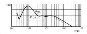
伝達関数とは、入力端に入力された信号と、出力端から出力される信号との関係を示す関数である。本実施形態では、入力端の電圧と出力端の電圧との比を、当該周波数との関係で表した関数(ゲイン特性)を用いるが、これ以外にも、入力端に入力された信号と、出力端から出力される信号との位相を、当該周波数との関係で表した関数(ゲイン特性)を用いてもよい。
本実施形態では、信号経路を、入出力装置220における音響信号の入力端からアンプ250の出力端Prまでとする。図9は、伝達関数の一例を示す図であって、比(デシベル)を縦軸にとり、周波数(Hz)を横軸にとった例である。
The transfer function is a function that indicates the relationship between a signal input to an input end and a signal output from an output end. In this embodiment, a function (gain characteristic) that expresses the ratio of the voltage at the input end to the voltage at the output end in relation to the frequency is used, but in addition to this, the signal input to the input end, A function (gain characteristic) expressing the phase of the signal output from the output terminal in relation to the frequency may be used.
In this embodiment, the signal path is from the audio signal input end of the input/
説明を図5に戻すと、制御装置110において構築される機能ブロックのうち、制御部112は、他の機能ブロックである取得部114、算出部116および判定部118を制御する。
取得部114は、音響クライアント20から送信された情報、具体的には、チェック対象の音響装置で計測された伝達関数Fr(x)を取得する。
Returning to FIG. 5, among the functional blocks constructed in the
The
算出部116は、チェック対象の音響装置における信号経路の伝達関数を算出する。
具体的には、算出部116は、チェック対象が例えば音響装置200aであれば、図6に示されるように、仮想入出力装置220v、仮想ミキサ230v、仮想プロセッサー240vおよび仮想アンプ250vを含む仮想装置をシミュレートにより作成する。なお、仮想入出力装置220vとは、音響装置200aにおける入出力装置220の回路構成をシミュレートしたものである。仮想ミキサ230vとは、音響装置200aにおけるミキサ230の回路構成をシミュレートしたものである。仮想プロセッサー240vとは、音響装置200aにおけるプロセッサー240の回路構成をシミュレートしたものである。仮想アンプ250vとは、音響装置200aにおけるアンプ250の回路構成をシミュレートしたものである。
算出部116は、第2に、作成した仮想装置にリストアデータを適用して、仮想装置を音響装置200aにおけるリストア時の状態に設定する。
算出部116は、第3に、仮想入出力装置220vのチャンネルIn1にピンクノイズを供給したときに仮想出力端Pvに現れる信号をシミュレートして求め、ピンクノイズとシミュレートして求めた信号とに基づいて、すなわち仮想装置における入力信号と仮想装置における出力信号とに基づいて、伝達関数Fv(x)を算出する。
なお、仮想入出力装置220vの入力端であるチャンネルIn1から仮想出力端Pvまでのの信号経路が第2信号経路の一例であり、伝達関数Fv(x)が第2伝達関数の一例である。
The
Specifically, if the check target is, for example, the
Second, the
Third, the
Note that the signal path from the channel In1, which is the input end of the virtual input/
判定部118は、伝達関数Fr(x)およびFv(x)を比較して、2つの伝達関数の類似度を求め、当該類似度に基づいて、音響装置200aの状態を判定する。具体的には、判定部118は、当該類似度が閾値以上であるか否かを判定し、当該類似度が閾値以上であれば、チェック対象の音響装置が正常であると判定する。一方、判定部118は、求めた類似度が閾値未満であれば、チェック対象の音響装置においてなんらかの異常があると判定する。
図10は、2つの伝達関数の比較の一例を示す図であって、破線が音響装置200aで計測された伝達関数Fr(x)の例であり、実線が管理サーバー10で算出された伝達関数Fv(x)の例である。
具体的には、判定部118は、2つの伝達関数の類似度を算出するにあたって、例えば周波数20Hz~20kHzの範囲において一定間隔(100Hz)毎に比の値(縦軸の値)の差を累積し、当該累積した差の値を類似度として算出してもよいし、他の算出法でもよい。
The
FIG. 10 is a diagram showing an example of a comparison of two transfer functions, in which the broken line is an example of the transfer function Fr(x) measured by the
Specifically, in calculating the similarity between two transfer functions, the
次に、処理装置210における制御装置2100が記憶装置2102に記憶されたプログラムを実行することによって構築される機能ブロックについて説明する。
Next, functional blocks constructed by the
図7は、制御装置2100で構築される機能ブロックを示す図である。制御装置2100では、機能ブロックとして、制御部2112、計測部2114および通信指示部2116が構築される。
制御部2112は、他の機能ブロックである計測部2114、通信指示部2116を制御する。
FIG. 7 is a diagram showing functional blocks constructed by the
The
計測部2114は、計測動作においてセンサー252で検出された電圧を解析し、例えば次のようにして伝達関数Fr(x)を求める。具体的には、計測部2114は、第1に、センサー252による検出された信号を解析し、周波数領域にわたって電圧を求める。第2に、計測部2114は、発振器222の出力特性、すなわちピンクノイズの強度と周波数との関係を取得する。
計測部2114は、第3に、センサー252で検出された信号を解析して得られた電圧のうち、ある周波数について着目し、ピンクノイズのうち、当該着目周波数と同じ周波数の強度を特定し、検出信号を解析して得られた電圧を、ピンクノイズで特定した周波数のの強度(電圧)で除して、当該着目周波数での比を求める。計測部2114は、第4に、着目周波数を異ならせながら、上記比の周波数特性を求める。ここで、着目周波数については、上述した通り例えば20Hz~20kHzであり、100Hzの間隔でシフトされる。
このようにして、計測部2114は、入出力装置220から出力端Prまでの信号経路における伝達関数Fr(x)を求める。
The
Thirdly, the
In this way, the
通信指示部2116は、管理サーバー10への情報の送信および管理サーバー10からの情報の受信を指示する。なお、本実施形態において、管理サーバー10に送信される情報には、例えば計測部2114によって求められた伝達関数Fr(x)があり、また、管理サーバー10から受信される情報には、計測動作の開始を指示する情報がある。
The
次に、音響チェックシステム1の動作について説明する。図8は、音響チェックシステム1の動作を示すフローチャートである。まず、ある1つの音響クライアント20における音響装置200aに着目し、当該着目する音響装置200aがチェック対象である場合について説明する。
Next, the operation of the
まず、管理サーバー10において制御部112は、音響装置200aについて計測の指示がなされたか否かを判定する(ステップSb10)。計測の指示がなされていないと判定すれば(ステップSb10の判定結果が「No」であれば)、制御部112は、処理手順をステップSb10に戻す。換言すれば、制御部112は、計測の指示がなされるまで手順がステップSb10を循環するので、実質的に待機状態となる。
音響装置200aの計測については、管理者が端末装置30を操作することによって指示してもよい。端末装置30での操作によって計測を指示する場合、管理者が管理する1または2以上の音響クライアントのうち、どの音響クライアントの、どの音響装置をチェック対象とするのかを適宜選択する構成としてもよい。また、音響装置200aの計測については、管理サーバー10で予め作成されたスケジュールにしたがった日時にて指示してもよい。
First, the control unit 112 in the
The administrator may instruct the measurement of the
計測の指示がなされたと判定すれば(ステップSb10の判定結果が「Yes」になれば)、制御部112は、データベースDbから音響装置200aのリストアデータを読み出す(ステップSb12)。なお、上記計測の指示の際に、複数セットのリストアデータのなかから1セットを選択するようにして、当該選択された1セットのリストアデータをデータベースDbから読み出すようにしてもよい。
制御部112は、読み出したリストアデータを算出部116と、チェック対象の音響装置200aに供給する。
If it is determined that the measurement instruction has been given (if the determination result in step Sb10 is "Yes"), the control unit 112 reads the restored data of the
The control unit 112 supplies the read restore data to the
算出部116は、仮想入出力装置220v、仮想ミキサ230v、仮想プロセッサー240vおよび仮想アンプ250vを含む仮想装置をシミュレートにより作成する(ステップSb14)。
算出部116は、作成した仮想装置にステップSb12で読み出されたリストアデータを適用する(ステップSb16)。これにより、仮想装置が音響装置200aにおけるリストア時の状態に設定される。
算出部116は、仮想入出力装置220vのチャンネルIn1にピンクノイズを供給したときに仮想出力端Pvに現れる信号をシミュレートして求めて、上述したように伝達関数Fv(x)を算出する(ステップSb18)。
算出部116は、算出した伝達関数Fv(x)を判定部118に供給する。
The
The
The
The
一方、リストアデータが供給された音響装置200aでは、制御部2112が、当該リストアデータを入出力装置220、ミキサ230、プロセッサー240およびアンプ250に適用する(ステップSb46)。これにより、音響装置200aでは、正常であれば、リストア時の設定状態が実際に再現される。
次に、制御部2112は、入出力装置220の発振器222にピンクノイズを出力させる一方で、計測部2114に伝達関数Fr(x)を求めるように指示する。
この指示にしたがって、計測部2114は、上述したように伝達関数Fr(x)を求めて(ステップSb48)、求めた伝達関数Fr(x)を通信指示部2116に供給する。
通信指示部2116は、通信装置2106に、計測部2114によって求められた伝達関数Fr(x)を管理サーバー10に送信することを指示する(ステップSb50)。この指示によって伝達関数Fr(x)は管理サーバー10に送信される。
なお、送信された伝達関数Fr(x)は、管理サーバー10において取得部114が取得する。取得部113は、取得した伝達関数Fr(x)を判定部118に供給する。
On the other hand, in the
Next, the
According to this instruction, the
The
Note that the transmitted transfer function Fr(x) is acquired by the
伝達関数Fr(x)、Fv(x)が供給された判定部118は、当該2つの伝達関数を比較して、類似度を求める(ステップSb20)。判定部118は、求めた類似度が閾値以上であるか否かを判定する(ステップSb22)。
判定部118は、求めた類似度が閾値以上であれば(ステップSb22の判定結果が「Yes」であれば)、2つの伝達関数同士が似ているので、音響装置200aが正常な状態にあると判定し(ステップSb24)、その判定結果を制御部112に供給する。
一方、判定部118は、求めた類似度が閾値未満であれば、2つの伝達関数同士が似ていないので、音響装置200aにおいてなんらかの異常があると判定し(ステップSb26)、その判定結果を制御部112に供給する。
The
The
On the other hand, if the obtained similarity is less than the threshold, the two transfer functions are not similar, and the
制御部112は、音響装置200aが正常であるか異常であるかの判定結果を、端末装置30に送信する(ステップSb28)。
判定結果を受信した端末装置30は、音響装置200aが正常であるか異常であるかの判定結果を例えば画面に表示する。この表示によって管理者は、音響装置200aが正常であるか異常であるかの判定結果を知ることができる。
The control unit 112 transmits the determination result as to whether the
The
音響装置200aにおいて入出力装置220、ミキサ230、プロセッサー240およびアンプ250にリストアデータが適用された場合に計測される伝達関数Fr(x)は、正常であれば、管理サーバー10において算出された伝達関数Fv(x)とほぼ同一となるはずである。
2つの伝達関数の類似度が閾値以上である場合、すなわち、計測された伝達関数Fr(x)が算出された伝達関数Fv(x)と相違している場合、音響装置200aから出力端Prまでの信号経路において、なんらかの異常があると考えられる。具体的には、音響装置200aにおける入出力装置220、ミキサ230、プロセッサー240またはアンプ250のうち少なくとも1つの異常、これらの要素間のケーブルの破損、接続ミスなどが発生している、と考えられる。
If the transfer function Fr(x) measured when the restore data is applied to the input/
When the similarity between the two transfer functions is greater than or equal to the threshold, that is, when the measured transfer function Fr(x) is different from the calculated transfer function Fv(x), the transfer function from the
本実施形態によれば、管理者は、音響装置200aの設置場所に出向き実際に自身の耳で確認することなく、当該音響装置200aにおける川上から川下までの信号経路、具体的には、入出力装置220の入力端から、ミキサ230、プロセッサー240、アンプ250の出力端Prまでの信号経路の正常/異常を知ることができるので、チェックの手間や時間などが大幅に低減される。またチェックに際し、熟練した技能も不要となる。
According to the present embodiment, the administrator can check the signal path from upstream to downstream in the
この動作の説明では、音響装置200aがチェック対象である場合を例にとったが、音響装置200b、200cがチェック対象として指定された場合も同様な動作となる。また、音響クライアント20に含まれる音響装置200a、200b、200cがすべてチェック対象であれば、これらの音響装置200a、200b、200cについても同様な動作が実行される。このため、音響クライアント20における音響装置200a、200b、200cの川上から川下までの信号経路についての正常/異常についても管理者は知ることができる。
なお、第1音響クライアント20-1~第n音響クライアント20-nのうち、1または2以上の音響クライアント20を指定し、さらに指定した音響クライアント20における1または2以上の音響装置をチェック対象としてもよい。
また、2以上の音響装置については同時にチェックしてもよいし、順番に1台ずつチェックしてもよい。
In the description of this operation, the case where the
Note that one or more
Furthermore, two or more audio devices may be checked at the same time, or one by one in order.
実施形態では、音響装置200aにおける入出力装置220の入力端からアンプ250の出力端Prまでの信号経路の伝達関数Fr(x)が、当該信号経路をシミュレートして算出された伝達関数Fv(x)と比較されて、当該音響装置200aの状態が判定された。比較する伝達関数の信号経路は、その一部同士であってもよい。具体的には次の通りである。
入出力装置220の入力端からアンプ250の出力端Prまでの信号経路は、入出力装置220、ミキサ230、プロセッサー240、アンプ250における各機器(および、これらの各要素を結ぶケーブル)に分解することができる。
そこでまず、判定部118は、比較する2つの伝達関数の信号経路を、入出力装置220(仮想入出力装置220v)のみとして、2つの伝達関数を比較する。判定部118は、この比較によって正常と判定すれば、比較する伝達関数の信号経路を、次のミキサ230(仮想ミキサ230v)の出力まで延長して、2つの伝達関数を比較する。判定部118は、この比較によって正常と判定すれば、比較する伝達関数の信号経路を、次のプロセッサー240(仮想プロセッサー240v)の出力まで延長して、2つの伝達関数を比較する。判定部118は、この比較によって正常と判定すれば、比較する伝達関数の信号経路を、次のアンプ250の出力端Pr(仮想アンプ250vの仮想出力端Pv)まで延長して、2つの伝達関数を比較する。なお、判定部118は、途中で異常と判定すれば、信号経路を次の機器まで延長しないで、判定を終了する。
In the embodiment, the transfer function Fr(x) of the signal path from the input end of the input/
The signal path from the input end of the input/
Therefore, first, the
このような判定において、ある機器まで正常であり、比較する伝達関数の信号経路が次の機器まで延長されたときに異常であると判定されれば、異常箇所が当該次の機器であると特定することができる。
また、入出力装置220、ミキサ230およびプロセッサー240のいずれかの状態が異常であると判定されれば、次の機器まで信号経路が延長されないので、異常を迅速に判定することができる。これは、入出力装置220の入力端からアンプ250の出力端Prまでの信号経路の全部についての伝達関数Fr(x)の計測および伝達関数Fv(x)の算出する必要がなく、当該信号経路の一部で済むからである。
このように、音響クライアント20の状態の判定には、当該音響クライアント20に含まれる音響装置200aの信号経路の状態判定のみならず、当該信号経路の途中に存在する機器の状態判定を含む。
In this kind of determination, if a certain device is normal and it is determined that the signal path of the transfer function being compared is abnormal when extended to the next device, the abnormality can be identified as the next device. can do.
Further, if it is determined that the state of any of the input/
In this way, determining the state of the
実施形態では、伝達関数Fr(x)、Fv(x)の類似度が閾値以上であれば、チェック対象の音響装置200aの状態が正常であると判定される。換言すれば、実施形態では、算出部116で算出される伝達関数Fv(x)が、計測部2114で求められた伝達関数Fv(x)と完全に一致しなくても、ある程度の相違が許容されて、正常であると判定される。
チェック対象の音響装置200aの状態が正常であれば、算出部116で算出された伝達関数Fv(x)は、計測部2114による求められた伝達関数Fr(x)と同じとなることが好ましい。逆にいえば、チェック対象の音響装置200aの状態が正常である場合に、算出された伝達関数Fv(x)が、計測された伝達関数Fr(x)と若干相違していれば、算出部116におけるシミュレートした内容が若干不正確であった可能性がある。
そこで、チェック対象の音響装置200aが正常である場合に、伝達関数Fv(x)が、伝達関数Fr(x)と相違していれば、算出部116は、伝達関数Fv(x)が伝達関数Fr(x)と一致するように、シミュレートした内容を修正して、次回以降において伝達関数Fv(x)の算出に反映させてもよい。この修正により、算出される伝達関数Fv(x)の精度を高めることができる。
In the embodiment, if the degree of similarity between the transfer functions Fr(x) and Fv(x) is equal to or greater than a threshold value, it is determined that the state of the
If the state of the
Therefore, if the
実施形態では、通信指示部2116が、処理装置210の制御装置2100に構築されたが、通信指示部2116の構築場所はこれ以外であってもよい。例えば、図11に示されるように、音響クライアント20と通信網Naとの間に位置する統括処理装置24に、通信指示部2116が構築されてもよい。
統括処理装置24は、例えばパーソナルコンピューター等の情報処理端末であり、管理サーバー10と音響クライアント20との間で情報の仲立ちをする。
統括処理装置24は、特に図示はしないが、制御装置および記憶装置を含む。当該制御装置が当該記憶装置に記憶されたプログラムを実行することによって、図12に示されるように、制御部2410と通信指示部2116とが構築される。なお、制御部2410は、通信指示部2116を制御する。
一方、音響装置200aにおける処理装置210で構築される機能ブロックには、通信指示部2116が存在せず、計測部2114で計測された伝達関数Fr(x)を制御部2112が、統括処理装置24における通信指示部2116に送信する。
In the embodiment, the
The
Although not particularly illustrated, the
On the other hand, the
なお、音響装置200b、200cについても同様である。例えば音響装置200bの処理装置210で構築される機能ブロックには通信指示部2116が存在せず、伝達関数を当該処理装置210の制御部2112が、統括処理装置24における通信指示部2116に送信する。このため、音響装置200a、200b、200cから同時に伝達関数が送信される場合が生じ得る。
統括処理装置24における通信指示部2116は、音響装置200a、200b、200cから送信された伝達関数の3つを、重要度や通信網Naの通信状態等を考慮して管理サーバー10に送信指示する。
このため、通信指示部2116が、統括処理装置24に構築される構成では、通信網Naにおけるトラフィックの逼迫を抑えることができる。
Note that the same applies to the
The
Therefore, in the configuration in which the
また、実施形態において、アンプ250にセンサー252を設けて、出力端Prに現れる電圧を検出して、当該電圧を処理装置210に供給し、当該処理装置210が伝達関数Fr(x)を求める構成とした。伝達関数Fr(x)を求めるにあたっては、この構成に限られない。例えば、スピーカー260の前にマイクロフォンを設けて、実際にスピーカー260で音響変換された音を信号に変換し、当該変換した信号を処理装置210に供給して、伝達関数Fr(x)を求めてもよい。
このようにすれば、入出力装置220から、ミキサ230、プロセッサー240およびアンプ250を順に経て、最終的にスピーカー260に至るまでの状態を判定することができる。
Further, in the embodiment, the amplifier 250 is provided with a
In this way, it is possible to determine the state of the signal from the input/
実施形態では、異常があると判定された場合に、その旨が端末装置30によって表示されるだけであった。これに限られれず、異常があると判定した場合に、管理者が音響装置200aを実際に点検した結果の報告情報を、異常と判定した伝達関数Fr(x)と関連付けてデータベースDbに登録してもよい。そして、以降のチェックにおいて、異常があると判定した場合に、データベースDbに登録された異常時の伝達関数Fr(x)のなかに、そのときに計測された伝達関数Fr(x)に近いものがあるかを判定し、近いものがあれば、その伝達関数に関連付けられた報告情報を読み出して、管理者に提示してもよい。これにより、管理者は、異常の理由をある程度把握できるので、異常を正常に復元する作業を迅速に実行することができる。
In the embodiment, when it is determined that there is an abnormality, the
<付記>
上述した実施形態等から、例えば以下のような態様が把握される。
<Additional notes>
For example, the following aspects can be understood from the above-described embodiments.
本開示の態様(第1態様)に係る管理サーバーは、音響信号の入力端からスピーカーまでの第1信号経路を有する音響クライアントを管理する管理サーバーであって、前記音響クライアントにおける前記第1信号経路の一部または全部について計測された第1伝達関数を取得する取得部と、前記音響クライアントにおける前記第1信号経路の一部または全部に対して、第2信号経路を仮想的に構築し、構築した前記第2信号経路の一部または全部についての第2伝達関数を算出する算出部と、前記第1伝達関数と前記第2伝達関数との比較結果に基づいて、前記音響クライアントの状態を判定する判定部と、を含む。
この態様によれば、音響信号の入力端からスピーカーまでの信号経路の一部または全部について計測された第1伝達関数と、仮想的に構築された信号経路の一部または全部について算出された第2伝達関数との比較結果に基づいて、音響クライアントの状態が判定される。したがって、管理者は、音響クライアントの設置場所に赴いて実際に自身の耳で確認することなく、当該音響クライアントの状態を知ることができるので、チェックの手間や時間などが大幅に低減される。またチェックに際し、熟練した技能も不要となる。
A management server according to an aspect (first aspect) of the present disclosure is a management server that manages an audio client having a first signal path from an input end of an audio signal to a speaker, the first signal path in the audio client. an acquisition unit that acquires a first transfer function measured for a part or all of the first signal path; and a second signal path virtually constructed for the part or all of the first signal path in the acoustic client; a calculation unit that calculates a second transfer function for part or all of the second signal path, and determines a state of the acoustic client based on a comparison result between the first transfer function and the second transfer function; and a determination unit.
According to this aspect, the first transfer function measured for part or all of the signal path from the input end of the acoustic signal to the speaker, and the first transfer function calculated for part or all of the virtually constructed signal path. Based on the comparison with the two transfer functions, the state of the acoustic client is determined. Therefore, the administrator can know the status of the audio client without going to the location where the audio client is installed and actually checking it with his/her own ears, which greatly reduces the effort and time required for checking. Additionally, no advanced skills are required for the check.
第1態様の例(第2態様)において、前記算出部は、前記仮想的に構築する前記第2信号経路を、前記比較結果に基づいて修正する。
この態様によれば、修正により、以後、算出される第2伝達関数Fv(x)の精度を高めることができる。
In the example of the first aspect (second aspect), the calculation unit modifies the virtually constructed second signal path based on the comparison result.
According to this aspect, the accuracy of the second transfer function Fv(x) calculated thereafter can be increased by the correction.
第1または第2態様の例(第3態様)において、前記音響クライアントにおける前記第1信号経路には、入出力装置、ミキサ、プロセッサーまたはアンプの少なくとも1つが含まれる。
この態様によれば、管理者は、入出力装置、ミキサ、プロセッサーまたはアンプの少なくとも1つが含まれる信号経路に異常があるか否かを知ることができる。
In an example of the first or second aspect (third aspect), the first signal path in the audio client includes at least one of an input/output device, a mixer, a processor, or an amplifier.
According to this aspect, the administrator can know whether there is an abnormality in the signal path including at least one of the input/output device, mixer, processor, or amplifier.
第1、第2または第3態様の例(第4態様)において、前記取得部による前記取得、前記算出部による前記算出、および、前記判定部による前記判定は、端末装置でなされた遠隔による指示によって開始する。
この態様によれば、端末装置でなされた遠隔の指示により、取得部による取得、算出部による算出、および、判定部による判定が開始するので、管理者の負担を低減することができる。
In the example of the first, second, or third aspect (fourth aspect), the acquisition by the acquisition unit, the calculation by the calculation unit, and the determination by the determination unit are performed by a remote instruction made by a terminal device. Start by.
According to this aspect, the acquisition by the acquisition unit, the calculation by the calculation unit, and the determination by the determination unit are started in response to a remote instruction given by the terminal device, so that the burden on the administrator can be reduced.
第4態様の例(第5態様)において、前記判定部による判定の結果を、前記端末装置に送信する。
この態様によれば、管理者は、操作した端末装置で判定結果を知ることができる。
In the example of the fourth aspect (fifth aspect), the determination result by the determination unit is transmitted to the terminal device.
According to this aspect, the administrator can know the determination result from the operated terminal device.
本開示の態様(第6態様)に係る音響チェック方法は、音響信号の入力端からスピーカーまでの第1信号経路を有する音響クライアントを管理するコンピューターが、前記音響クライアントにおける前記第1信号経路の一部または全部について計測された第1伝達関数を取得し、前記音響クライアントにおける前記第1信号経路の一部または全部に対して、第2信号経路を仮想的に構築し、構築した前記第2信号経路の一部または全部についての第2伝達関数を算出し、前記第1伝達関数と前記第2伝達関数との比較結果に基づいて、前記音響クライアントの状態を判定する。 In the acoustic check method according to an aspect (sixth aspect) of the present disclosure, a computer that manages an acoustic client having a first signal path from an input end of an acoustic signal to a speaker controls one of the first signal paths in the acoustic client. obtain a first transfer function measured for part or all of the part, virtually construct a second signal path for part or all of the first signal path in the acoustic client, and generate the constructed second signal. A second transfer function for part or all of the route is calculated, and a state of the acoustic client is determined based on a comparison result between the first transfer function and the second transfer function.
本開示の態様(第7態様)に係るプログラムは、音響信号の入力端からスピーカーまでの第1信号経路を有する音響クライアントを管理するコンピュータを、前記音響クライアントにおける前記第1信号経路の一部または全部について計測された第1伝達関数を取得する取得部、前記音響クライアントにおける前記第1信号経路の一部または全部に対して、第2信号経路を仮想的に構築し、構築した前記第2信号経路の一部または全部についての第2伝達関数を算出する算出部、および、前記第1伝達関数と前記第2伝達関数との比較結果に基づいて、前記音響クライアントの状態を判定する判定部、として機能させる。 A program according to an aspect (seventh aspect) of the present disclosure causes a computer that manages an audio client having a first signal path from an input end of an audio signal to a speaker to control a part of the first signal path in the audio client or an acquisition unit that acquires a first transfer function measured for all of the first transfer functions; an acquisition unit that virtually constructs a second signal path for part or all of the first signal path in the acoustic client; and the constructed second signal; a calculation unit that calculates a second transfer function for part or all of the route; and a determination unit that determines the state of the acoustic client based on a comparison result between the first transfer function and the second transfer function. function as
このように、例示した各態様の管理サーバーは、音響チェックとしても、また、当該管理サーバーをコンピューターに実行させるプログラムとしても実現され得る。 In this way, the management server of each of the illustrated aspects can be realized as an acoustic check or as a program that causes a computer to execute the management server.
本開示の態様(第8態様)に係る音響クライアントは、音響信号の入力端からスピーカーまでの第1信号経路を有し、管理サーバーに接続される音響クライアントであって、前記第1信号経路の一部または全部についての第1伝達関数を計測する計測部と、前記計測部で計測された第1伝達関数を前記管理サーバーに送信することを指示する通信指示部と、を有し、前記管理サーバーが前記第1伝達関数に基づいて前記音響クライアントの状態を判定する。
この態様によれば、管理サーバーが、音響クライアントの信号経路についての第1伝達関数に基づいて、音響クライアントの状態を判定するので、管理者は、音響クライアントの設置場所に赴いて実際に自身の耳で確認する必要がない。
An audio client according to an aspect (eighth aspect) of the present disclosure is an audio client that has a first signal path from an input end of an audio signal to a speaker and is connected to a management server, wherein the first signal path is connected to a management server. a measurement unit that measures a first transfer function for some or all of the parts, and a communication instruction unit that instructs to transmit the first transfer function measured by the measurement unit to the management server, A server determines a state of the acoustic client based on the first transfer function.
According to this aspect, the management server determines the state of the audio client based on the first transfer function for the signal path of the audio client, so the administrator can go to the installation location of the audio client and actually check the state of the audio client. There is no need to check with your ears.
第8態様の例(第9態様)において、前記音響クライアントは、統括処理装置を含み、前記統括処理装置は、前記通信指示部を含む。 In the example of the eighth aspect (ninth aspect), the audio client includes a general processing device, and the general processing device includes the communication instruction section.
本開示の態様(第10態様)に係る音響チェックシステムは、管理サーバーと、スピーカーを含む音響クライアントとを有する音響チェックシステムであって、前記音響クライアントは、前記第1信号経路の一部または全部についての第1伝達関数を計測する計測部と、前記計測部で計測された第1伝達関数を前記管理サーバーに送信することを指示する通信指示部と、を有し、前記管理サーバーは、前記指示により送信された前記第1伝達関数を取得する取得部と、前記音響クライアントにおける前記第1信号経路の一部または全部に対して、第2信号経路を仮想的に構築し、構築した前記第2信号経路の一部または全部についての第2伝達関数を算出する算出部と、前記第1伝達関数と前記第2伝達関数との比較結果に基づいて、前記音響クライアントの状態を判定する判定部と、を含む。 An acoustic check system according to an aspect (tenth aspect) of the present disclosure is an acoustic check system having a management server and an acoustic client including a speaker, wherein the acoustic client includes part or all of the first signal path. a measurement unit that measures a first transfer function for the measurement unit; and a communication instruction unit that instructs the management server to transmit the first transfer function measured by the measurement unit, and the management server an acquisition unit that acquires the first transfer function transmitted in accordance with an instruction; and a second signal path that is virtually constructed for part or all of the first signal path in the acoustic client; a calculation unit that calculates a second transfer function for part or all of two signal paths; and a determination unit that determines the state of the acoustic client based on a comparison result between the first transfer function and the second transfer function. and, including.
第10態様の例(第11態様)において、前記音響クライアントにおける前記第1信号経路における状態は、リストアデータに基づいて定義され、前記算出部は、前記リストアデータに基づいて前記第2信号経路を仮想的に構築し、前記計測部は、前記リストアデータに基づいて定義された前記第1信号経路についての第1伝達関数を計測する。 In the example of the tenth aspect (eleventh aspect), the state of the first signal path in the audio client is defined based on restored data, and the calculation unit defines the state of the second signal path based on the restored data. The measurement unit measures a first transfer function for the first signal path defined based on the restored data.
1…音響チェックシステム、10…管理サーバー、20…音響クライアント、114…取得部、116…算出部、118…判定部、200…音響装置、210…処理装置、2114…計測部、2116…通信指示部。
DESCRIPTION OF
Claims (11)
前記音響クライアントにおける前記第1信号経路の一部または全部について計測された第1伝達関数を取得する取得部と、
前記音響クライアントにおける前記第1信号経路の一部または全部に対して、第2信号経路を仮想的に構築し、構築した前記第2信号経路の一部または全部についての第2伝達関数を算出する算出部と、
前記第1伝達関数と前記第2伝達関数との比較結果に基づいて、前記音響クライアントの状態を判定する判定部と、
を含む管理サーバー。 A management server that manages an audio client having a first signal path from an audio signal input end to a speaker,
an acquisition unit that acquires a first transfer function measured for part or all of the first signal path in the acoustic client;
Virtually constructing a second signal path for part or all of the first signal path in the acoustic client, and calculating a second transfer function for part or all of the constructed second signal path. A calculation section,
a determination unit that determines a state of the audio client based on a comparison result between the first transfer function and the second transfer function;
Management server containing.
前記仮想的に構築する前記第2信号経路を、前記比較結果に基づいて修正する
請求項1に記載の管理サーバー。 The calculation unit is
The management server according to claim 1, wherein the second signal path that is virtually constructed is modified based on the comparison result.
請求項1または2に記載の管理サーバー。 the first signal path in the audio client includes at least one of an input/output device, a mixer, a processor, or an amplifier;
The management server according to claim 1 or 2.
請求項1乃至3のいずれかに記載の管理サーバー。 The management server according to any one of claims 1 to 3, wherein the acquisition by the acquisition unit, the calculation by the calculation unit, and the determination by the determination unit are started by a remote instruction issued from a terminal device.
請求項4に記載の管理サーバー。 transmitting a result of the determination by the determination unit to the terminal device;
The management server according to claim 4.
前記音響クライアントにおける前記第1信号経路の一部または全部について計測された第1伝達関数を取得し、
前記音響クライアントにおける前記第1信号経路の一部または全部に対して、第2信号経路を仮想的に構築し、
構築した前記第2信号経路の一部または全部についての第2伝達関数を算出し、
前記第1伝達関数と前記第2伝達関数との比較結果に基づいて、前記音響クライアントの状態を判定する
音響チェック方法。 A computer managing an audio client having a first signal path from an audio signal input end to a speaker,
obtaining a first transfer function measured for part or all of the first signal path in the acoustic client;
Virtually constructing a second signal path for part or all of the first signal path in the acoustic client,
Calculating a second transfer function for part or all of the constructed second signal path,
An acoustic check method, comprising: determining a state of the acoustic client based on a comparison result between the first transfer function and the second transfer function.
前記音響クライアントにおける前記第1信号経路の一部または全部について計測された第1伝達関数を取得する取得部、
前記音響クライアントにおける前記第1信号経路の一部または全部に対して、第2信号経路を仮想的に構築し、構築した前記第2信号経路の一部または全部についての第2伝達関数を算出する算出部、および、
前記第1伝達関数と前記第2伝達関数との比較結果に基づいて、前記音響クライアントの状態を判定する判定部、
として機能させるプログラム。 A computer that manages an audio client having a first signal path from an audio signal input end to a speaker,
an acquisition unit that acquires a first transfer function measured for part or all of the first signal path in the acoustic client;
Virtually constructing a second signal path for part or all of the first signal path in the acoustic client, and calculating a second transfer function for part or all of the constructed second signal path. a calculation section, and
a determination unit that determines a state of the audio client based on a comparison result between the first transfer function and the second transfer function;
A program that functions as
前記第1信号経路の一部または全部についての第1伝達関数を計測する計測部と、
前記計測部で計測された第1伝達関数を前記管理サーバーに送信することを指示する通信指示部と、
を有し、
前記管理サーバーが
前記第1伝達関数に基づいて前記音響クライアントの状態を判定する
音響クライアント。 An acoustic client having a first signal path from an input end of an acoustic signal to a speaker and connected to a management server,
a measurement unit that measures a first transfer function for part or all of the first signal path;
a communication instruction unit that instructs to transmit the first transfer function measured by the measurement unit to the management server;
has
The acoustic client, wherein the management server determines a state of the acoustic client based on the first transfer function.
前記統括処理装置は、前記通信指示部を含む
請求項8に記載の音響クライアント。 The audio client includes a general processing device,
The audio client according to claim 8, wherein the overall processing device includes the communication instruction section.
前記音響クライアントは、
第1信号経路の一部または全部についての第1伝達関数を計測する計測部と、
前記計測部で計測された第1伝達関数を前記管理サーバーに送信することを指示する通信指示部と、
を有し、
前記管理サーバーは、
前記指示により送信された前記第1伝達関数を取得する取得部と、
前記音響クライアントにおける前記第1信号経路の一部または全部に対して、第2信号経路を仮想的に構築し、構築した前記第2信号経路の一部または全部についての第2伝達関数を算出する算出部と、
前記第1伝達関数と前記第2伝達関数との比較結果に基づいて、前記音響クライアントの状態を判定する判定部と、
を含む音響チェックシステム。 An acoustic check system having a management server and an acoustic client including speakers, the system comprising:
The acoustic client includes:
a measurement unit that measures a first transfer function for part or all of the first signal path;
a communication instruction unit that instructs to transmit the first transfer function measured by the measurement unit to the management server;
has
The management server is
an acquisition unit that acquires the first transfer function transmitted according to the instruction;
Virtually constructing a second signal path for part or all of the first signal path in the acoustic client, and calculating a second transfer function for part or all of the constructed second signal path. A calculation section,
a determination unit that determines a state of the audio client based on a comparison result between the first transfer function and the second transfer function;
Acoustic check system including.
前記算出部は、前記リストアデータに基づいて前記第2信号経路を仮想的に構築し、
前記計測部は、前記リストアデータに基づいて定義された前記第1信号経路についての第1伝達関数を計測する、
請求項10に記載の音響チェックシステム。
a state in the first signal path in the acoustic client is defined based on restored data;
The calculation unit virtually constructs the second signal path based on the restored data,
The measuring unit measures a first transfer function for the first signal path defined based on the restored data.
The acoustic check system according to claim 10.
Priority Applications (4)
| Application Number | Priority Date | Filing Date | Title |
|---|---|---|---|
| JP2020015328A JP7409121B2 (en) | 2020-01-31 | 2020-01-31 | Management server, acoustic check method, program, acoustic client and acoustic check system |
| EP21153709.7A EP3859518B1 (en) | 2020-01-31 | 2021-01-27 | Management server, audio testing method, audio client system, and audio testing system |
| CN202110118269.XA CN113207066B (en) | 2020-01-31 | 2021-01-28 | Management server, sound inspection method, recording medium, sound client, and sound inspection system |
| US17/162,672 US11558704B2 (en) | 2020-01-31 | 2021-01-29 | Management server, audio testing method, audio client system, and audio testing system |
Applications Claiming Priority (1)
| Application Number | Priority Date | Filing Date | Title |
|---|---|---|---|
| JP2020015328A JP7409121B2 (en) | 2020-01-31 | 2020-01-31 | Management server, acoustic check method, program, acoustic client and acoustic check system |
Publications (2)
| Publication Number | Publication Date |
|---|---|
| JP2021125707A JP2021125707A (en) | 2021-08-30 |
| JP7409121B2 true JP7409121B2 (en) | 2024-01-09 |
Family
ID=74285379
Family Applications (1)
| Application Number | Title | Priority Date | Filing Date |
|---|---|---|---|
| JP2020015328A Active JP7409121B2 (en) | 2020-01-31 | 2020-01-31 | Management server, acoustic check method, program, acoustic client and acoustic check system |
Country Status (4)
| Country | Link |
|---|---|
| US (1) | US11558704B2 (en) |
| EP (1) | EP3859518B1 (en) |
| JP (1) | JP7409121B2 (en) |
| CN (1) | CN113207066B (en) |
Families Citing this family (1)
| Publication number | Priority date | Publication date | Assignee | Title |
|---|---|---|---|---|
| AU2021258132A1 (en) * | 2020-04-19 | 2022-12-15 | Sonova Ag | Systems and methods for remote administration of hearing tests |
Citations (2)
| Publication number | Priority date | Publication date | Assignee | Title |
|---|---|---|---|---|
| JP2018157283A (en) | 2017-03-15 | 2018-10-04 | ヤマハ株式会社 | Signal processing apparatus, signal processing method, and program |
| JP2019169756A (en) | 2018-03-22 | 2019-10-03 | ヤマハ株式会社 | Acoustic apparatus, server, acoustic system, control method for acoustic apparatus and program |
Family Cites Families (14)
| Publication number | Priority date | Publication date | Assignee | Title |
|---|---|---|---|---|
| DE69323874T2 (en) * | 1992-05-20 | 1999-12-02 | Ind Res Ltd | IMPROVEMENTS IN A BROADBAND REVERBERATION SYSTEM |
| JP2001025086A (en) * | 1999-07-09 | 2001-01-26 | Sound Vision:Kk | System and hall for stereoscopic sound reproduction |
| US7053705B2 (en) * | 2003-12-22 | 2006-05-30 | Tymphany Corporation | Mixed-mode (current-voltage) audio amplifier |
| JP4674505B2 (en) * | 2005-08-01 | 2011-04-20 | ソニー株式会社 | Audio signal processing method, sound field reproduction system |
| JP2007142875A (en) * | 2005-11-18 | 2007-06-07 | Sony Corp | Acoustic characteristic corrector |
| CN101477797A (en) * | 2008-11-24 | 2009-07-08 | 广州励丰声光科技有限公司 | Simulation system for hall acoustic environment |
| US8194869B2 (en) * | 2010-03-17 | 2012-06-05 | Harman International Industries, Incorporated | Audio power management system |
| JP2012004668A (en) * | 2010-06-14 | 2012-01-05 | Sony Corp | Head transmission function generation device, head transmission function generation method, and audio signal processing apparatus |
| EP2661912B1 (en) * | 2011-01-05 | 2018-08-22 | Koninklijke Philips N.V. | An audio system and method of operation therefor |
| US9179237B2 (en) * | 2011-12-16 | 2015-11-03 | Bose Corporation | Virtual audio system tuning |
| US10129682B2 (en) * | 2012-01-06 | 2018-11-13 | Bacch Laboratories, Inc. | Method and apparatus to provide a virtualized audio file |
| GB201318802D0 (en) * | 2013-10-24 | 2013-12-11 | Linn Prod Ltd | Linn Exakt |
| CN106507240A (en) * | 2015-09-04 | 2017-03-15 | 音乐集团公司 | A kind of physical location of the speaker by speaker system is associated to the method for speaker identifier |
| US9930463B2 (en) * | 2016-03-31 | 2018-03-27 | Sonos, Inc. | Defect detection via audio playback |
-
2020
- 2020-01-31 JP JP2020015328A patent/JP7409121B2/en active Active
-
2021
- 2021-01-27 EP EP21153709.7A patent/EP3859518B1/en active Active
- 2021-01-28 CN CN202110118269.XA patent/CN113207066B/en active Active
- 2021-01-29 US US17/162,672 patent/US11558704B2/en active Active
Patent Citations (2)
| Publication number | Priority date | Publication date | Assignee | Title |
|---|---|---|---|---|
| JP2018157283A (en) | 2017-03-15 | 2018-10-04 | ヤマハ株式会社 | Signal processing apparatus, signal processing method, and program |
| JP2019169756A (en) | 2018-03-22 | 2019-10-03 | ヤマハ株式会社 | Acoustic apparatus, server, acoustic system, control method for acoustic apparatus and program |
Also Published As
| Publication number | Publication date |
|---|---|
| CN113207066A (en) | 2021-08-03 |
| JP2021125707A (en) | 2021-08-30 |
| EP3859518B1 (en) | 2024-02-21 |
| US11558704B2 (en) | 2023-01-17 |
| EP3859518A1 (en) | 2021-08-04 |
| CN113207066B (en) | 2023-02-28 |
| US20210243543A1 (en) | 2021-08-05 |
Similar Documents
| Publication | Publication Date | Title |
|---|---|---|
| US8126156B2 (en) | Calibrating at least one system microphone | |
| JP5450049B2 (en) | Method and apparatus in an acoustic system | |
| JP5729905B2 (en) | Audio system calibration method and apparatus | |
| US8208647B2 (en) | Method and device for determining a room acoustic impulse response in the time domain | |
| US11626850B2 (en) | Automated tuning by measuring and equalizing speaker output in an audio environment | |
| JP7409121B2 (en) | Management server, acoustic check method, program, acoustic client and acoustic check system | |
| US20230079741A1 (en) | Automated audio tuning launch procedure and report | |
| WO2019001158A1 (en) | Method and apparatus for determining position of loudspeaker, and loudspeaker | |
| US20190087739A1 (en) | Linear model to predict listener preference ratings of headphones | |
| US20230367543A1 (en) | Source-based sound quality adjustment tool | |
| JP7069910B2 (en) | Audio equipment, servers, audio systems, audio equipment control methods and server control methods | |
| Welti et al. | Validation of a virtual in-ear headphone listening test method | |
| CN108574914B (en) | Method and device for adjusting multicast playback file of sound box and receiving end | |
| KR102245742B1 (en) | Uninterrupted audio device using real-time audio amplifier detector technology | |
| JP4760524B2 (en) | Control device, routing verification method, and routing verification program | |
| WO2016173440A1 (en) | Audio connecting line detection method and device | |
| KR102437807B1 (en) | Public address monitoring based on signal correlation determined for extensible search range | |
| BE1022225B1 (en) | Broadcasting system | |
| US9589550B2 (en) | Methods and systems for measuring and reporting an energy level of a sound component within a sound mix | |
| JP2014039239A (en) | Acoustic signal processing apparatus, program and processing method of acoustic signal | |
| US20230146772A1 (en) | Automated audio tuning and compensation procedure | |
| KR102494043B1 (en) | Public adress monitoring based on additional signal correlation determined along reduced time interval | |
| JP5652223B2 (en) | Echo canceller evaluation apparatus and echo canceller evaluation method | |
| JP2021125708A (en) | Management server, acoustic management method, program, acoustic client, and acoustic management system | |
| WO2016165056A1 (en) | Board testing method, board and system |
Legal Events
| Date | Code | Title | Description |
|---|---|---|---|
| A621 | Written request for application examination |
Free format text: JAPANESE INTERMEDIATE CODE: A621 Effective date: 20221118 |
|
| A977 | Report on retrieval |
Free format text: JAPANESE INTERMEDIATE CODE: A971007 Effective date: 20230718 |
|
| A131 | Notification of reasons for refusal |
Free format text: JAPANESE INTERMEDIATE CODE: A131 Effective date: 20230808 |
|
| A521 | Request for written amendment filed |
Free format text: JAPANESE INTERMEDIATE CODE: A523 Effective date: 20230814 |
|
| TRDD | Decision of grant or rejection written | ||
| A01 | Written decision to grant a patent or to grant a registration (utility model) |
Free format text: JAPANESE INTERMEDIATE CODE: A01 Effective date: 20231121 |
|
| A61 | First payment of annual fees (during grant procedure) |
Free format text: JAPANESE INTERMEDIATE CODE: A61 Effective date: 20231204 |
|
| R151 | Written notification of patent or utility model registration |
Ref document number: 7409121 Country of ref document: JP Free format text: JAPANESE INTERMEDIATE CODE: R151 |