EP3770853A1 - Procédé de traitement d'image, programme informatique et support d'enregistrement - Google Patents
Procédé de traitement d'image, programme informatique et support d'enregistrement Download PDFInfo
- Publication number
- EP3770853A1 EP3770853A1 EP18911181.8A EP18911181A EP3770853A1 EP 3770853 A1 EP3770853 A1 EP 3770853A1 EP 18911181 A EP18911181 A EP 18911181A EP 3770853 A1 EP3770853 A1 EP 3770853A1
- Authority
- EP
- European Patent Office
- Prior art keywords
- image
- cell
- block
- feature amount
- original image
- Prior art date
- Legal status (The legal status is an assumption and is not a legal conclusion. Google has not performed a legal analysis and makes no representation as to the accuracy of the status listed.)
- Pending
Links
- 238000003672 processing method Methods 0.000 title claims abstract description 17
- 238000004590 computer program Methods 0.000 title claims description 5
- 210000004027 cell Anatomy 0.000 claims abstract description 170
- 210000004748 cultured cell Anatomy 0.000 claims abstract description 5
- 238000003384 imaging method Methods 0.000 claims description 43
- 238000012545 processing Methods 0.000 description 68
- 230000011218 segmentation Effects 0.000 description 26
- 238000000034 method Methods 0.000 description 25
- 238000006243 chemical reaction Methods 0.000 description 21
- 238000010586 diagram Methods 0.000 description 15
- 239000001963 growth medium Substances 0.000 description 10
- 230000006870 function Effects 0.000 description 8
- 230000008569 process Effects 0.000 description 8
- 230000008859 change Effects 0.000 description 6
- 230000006835 compression Effects 0.000 description 6
- 238000007906 compression Methods 0.000 description 6
- 238000000605 extraction Methods 0.000 description 6
- 238000004422 calculation algorithm Methods 0.000 description 3
- 238000003708 edge detection Methods 0.000 description 2
- 238000005286 illumination Methods 0.000 description 2
- 239000002609 medium Substances 0.000 description 2
- 238000012986 modification Methods 0.000 description 2
- 230000004048 modification Effects 0.000 description 2
- 230000009467 reduction Effects 0.000 description 2
- 210000003771 C cell Anatomy 0.000 description 1
- 230000008901 benefit Effects 0.000 description 1
- 239000003153 chemical reaction reagent Substances 0.000 description 1
- 239000003814 drug Substances 0.000 description 1
- 229940079593 drug Drugs 0.000 description 1
- 230000000694 effects Effects 0.000 description 1
- 239000004973 liquid crystal related substance Substances 0.000 description 1
- 230000007774 longterm Effects 0.000 description 1
- 238000010801 machine learning Methods 0.000 description 1
- 238000012805 post-processing Methods 0.000 description 1
- 210000001082 somatic cell Anatomy 0.000 description 1
- 230000002194 synthesizing effect Effects 0.000 description 1
- XLYOFNOQVPJJNP-UHFFFAOYSA-N water Substances O XLYOFNOQVPJJNP-UHFFFAOYSA-N 0.000 description 1
Images


Classifications
-
- G—PHYSICS
- G06—COMPUTING; CALCULATING OR COUNTING
- G06T—IMAGE DATA PROCESSING OR GENERATION, IN GENERAL
- G06T7/00—Image analysis
- G06T7/10—Segmentation; Edge detection
- G06T7/11—Region-based segmentation
-
- G—PHYSICS
- G01—MEASURING; TESTING
- G01N—INVESTIGATING OR ANALYSING MATERIALS BY DETERMINING THEIR CHEMICAL OR PHYSICAL PROPERTIES
- G01N33/00—Investigating or analysing materials by specific methods not covered by groups G01N1/00 - G01N31/00
- G01N33/48—Biological material, e.g. blood, urine; Haemocytometers
- G01N33/483—Physical analysis of biological material
- G01N33/4833—Physical analysis of biological material of solid biological material, e.g. tissue samples, cell cultures
-
- G—PHYSICS
- G06—COMPUTING; CALCULATING OR COUNTING
- G06F—ELECTRIC DIGITAL DATA PROCESSING
- G06F18/00—Pattern recognition
- G06F18/20—Analysing
- G06F18/24—Classification techniques
- G06F18/245—Classification techniques relating to the decision surface
-
- G—PHYSICS
- G06—COMPUTING; CALCULATING OR COUNTING
- G06T—IMAGE DATA PROCESSING OR GENERATION, IN GENERAL
- G06T3/00—Geometric image transformations in the plane of the image
- G06T3/40—Scaling of whole images or parts thereof, e.g. expanding or contracting
-
- G—PHYSICS
- G06—COMPUTING; CALCULATING OR COUNTING
- G06T—IMAGE DATA PROCESSING OR GENERATION, IN GENERAL
- G06T7/00—Image analysis
- G06T7/10—Segmentation; Edge detection
- G06T7/168—Segmentation; Edge detection involving transform domain methods
-
- G—PHYSICS
- G06—COMPUTING; CALCULATING OR COUNTING
- G06T—IMAGE DATA PROCESSING OR GENERATION, IN GENERAL
- G06T7/00—Image analysis
- G06T7/10—Segmentation; Edge detection
- G06T7/194—Segmentation; Edge detection involving foreground-background segmentation
-
- G—PHYSICS
- G06—COMPUTING; CALCULATING OR COUNTING
- G06V—IMAGE OR VIDEO RECOGNITION OR UNDERSTANDING
- G06V10/00—Arrangements for image or video recognition or understanding
- G06V10/40—Extraction of image or video features
- G06V10/50—Extraction of image or video features by performing operations within image blocks; by using histograms, e.g. histogram of oriented gradients [HoG]; by summing image-intensity values; Projection analysis
-
- G—PHYSICS
- G06—COMPUTING; CALCULATING OR COUNTING
- G06V—IMAGE OR VIDEO RECOGNITION OR UNDERSTANDING
- G06V10/00—Arrangements for image or video recognition or understanding
- G06V10/94—Hardware or software architectures specially adapted for image or video understanding
- G06V10/945—User interactive design; Environments; Toolboxes
-
- G—PHYSICS
- G06—COMPUTING; CALCULATING OR COUNTING
- G06V—IMAGE OR VIDEO RECOGNITION OR UNDERSTANDING
- G06V20/00—Scenes; Scene-specific elements
- G06V20/60—Type of objects
- G06V20/69—Microscopic objects, e.g. biological cells or cellular parts
- G06V20/695—Preprocessing, e.g. image segmentation
-
- G—PHYSICS
- G06—COMPUTING; CALCULATING OR COUNTING
- G06V—IMAGE OR VIDEO RECOGNITION OR UNDERSTANDING
- G06V20/00—Scenes; Scene-specific elements
- G06V20/60—Type of objects
- G06V20/69—Microscopic objects, e.g. biological cells or cellular parts
- G06V20/698—Matching; Classification
-
- G—PHYSICS
- G06—COMPUTING; CALCULATING OR COUNTING
- G06T—IMAGE DATA PROCESSING OR GENERATION, IN GENERAL
- G06T2207/00—Indexing scheme for image analysis or image enhancement
- G06T2207/20—Special algorithmic details
- G06T2207/20021—Dividing image into blocks, subimages or windows
-
- G—PHYSICS
- G06—COMPUTING; CALCULATING OR COUNTING
- G06T—IMAGE DATA PROCESSING OR GENERATION, IN GENERAL
- G06T2207/00—Indexing scheme for image analysis or image enhancement
- G06T2207/20—Special algorithmic details
- G06T2207/20048—Transform domain processing
- G06T2207/20052—Discrete cosine transform [DCT]
-
- G—PHYSICS
- G06—COMPUTING; CALCULATING OR COUNTING
- G06T—IMAGE DATA PROCESSING OR GENERATION, IN GENERAL
- G06T2207/00—Indexing scheme for image analysis or image enhancement
- G06T2207/20—Special algorithmic details
- G06T2207/20092—Interactive image processing based on input by user
- G06T2207/20101—Interactive definition of point of interest, landmark or seed
-
- G—PHYSICS
- G06—COMPUTING; CALCULATING OR COUNTING
- G06T—IMAGE DATA PROCESSING OR GENERATION, IN GENERAL
- G06T2207/00—Indexing scheme for image analysis or image enhancement
- G06T2207/30—Subject of image; Context of image processing
- G06T2207/30004—Biomedical image processing
- G06T2207/30024—Cell structures in vitro; Tissue sections in vitro
Definitions
- This invention relates to an image processing technique for dividing a cell area and another area from an image captured in a culture environment and including a cell image and a background image thereof.
- a cell area which is a primary imaging object, and an area equivalent to a background image of the cell image may be distinguished in the image.
- a boundary between the cell image and the background image needs to be defined.
- a cell area has been specified, for example, by dying the cell with a drug or adding a fluorescence reagent.
- a cell in a culture medium is close to transparent and has a refractive index not much different from that of water.
- a boundary between a cell image and a background image is often unclear.
- An image processing technique such as a binarization processing utilizing a luminance difference between a cell image and a background image or edge detection for extracting a cell contour can be utilized to distinguish the cell image and the background image in an image.
- This invention was developed in view of the above problem and an object thereof is to provide a technique capable of properly segmenting a cell area and another area from an image including a cell image and a background image.
- one aspect of an image processing method includes obtaining an original image including a cultured cell image with a background image, dividing the original image into blocks each composed of a predetermined number of pixels and obtaining a spatial frequency component of an image in each block for each block, setting a total of intensities of low frequency components having a frequency equal to or lower than a predetermined frequency as a first feature amount, setting a total of intensities of high frequency components having a higher frequency than the low frequency component as a second feature amount and classifying each block as the one belonging to a cell cluster corresponding to the cell or the one belonging to other than the cell cluster in a two-dimensional feature amount space composed of the first feature amounts and the second feature amounts, and segmenting the original image into an area occupied by the blocks classified as the cell cluster and another area.
- an image is segmented based on a distribution of local spatial frequency components in the image. Specifically, the image is divided into blocks and the spatial frequency component is obtained for each block. Out of the spatial frequency components, the low frequency component represents a moderate luminance change in the block and the high frequency component represents a state of a finer luminance change. Note that, out of the low frequency components, a direct-current component particularly represents an average luminance of the entire block. Thus, in the case of expressing the block by the intensity of each spatial frequency component in this way, the low frequency component reflects the brightness of this block and the high frequency component reflects a texture in the block.
- positions occupied in the two-dimensional feature amount space are considered. Then a significant difference appears in a distribution of the feature amounts between the blocks falling under the cell area and blocks falling under the background, and these blocks form mutually independent clusters. If a debris image is included in the image, the blocks falling under the debris image form a cluster different from the clusters of both the cell and the background. Utilizing this, the positions in the original image occupied by the blocks belonging to the cell cluster in the feature amount space can be regarded as the cell area. By doing so, the cell area can be precisely extracted from the original image without being affected by the debris.
- the image processing method according to the invention can make a computer an execution subject.
- the invention can be realized as a computer program for causing the computer to perform the above processing. Further, the invention can be realized as a recording medium recording this computer program.
- a block is equivalent to a cell is evaluated based on features of a spatial frequency component of an image in the block for each of the blocks obtained by dividing an original image.
- a cell area and another area can be properly separated from an image including a cell image and a background image.
- An image processing in this embodiment is an area segmentation processing for extracting a cell area from an image captured by imaging a cell or an aggregate of cells cultured in a culture medium.
- This image processing is performed for an unprocessed original image captured by an imaging device having an imaging function of imaging a specimen including a cell.
- the imaging device can perform this image processing as one of post-processings for image data after imaging.
- a computer device having received image data from the imaging device or an appropriate storage may perform this image processing.
- a general-purpose computer device performs the image processing of the present embodiment on original image data generated by imaging which is already performed.
- the configuration of the imaging apparatus is not particularly limited only if the imaging apparatus has a function of imaging a sample including cultured cells together with a culture medium and outputting the captured image as digital image data. Further, it is preferable that the image should be a bright field image.
- the computer device having a general hardware configuration which is commercialized as, for example, a personal computer, can be used. Hereinafter, detailed description on the hardware will be omitted.
- FIG. 1 is a flow chart showing an area segmentation processing of this embodiment.
- the computer device obtains an original image (Step S101).
- the original image is an image obtained by bright-field imaging a specimen including a cell cultured in a culture medium under appropriate imaging conditions by an appropriate imaging device, and assumed to include at least one entire cell image.
- the original image can include images of at least one cell and a debris other than the cell around the cell, a background and the like.
- the resolution conversion is a processing of converting a pixel size of the original image at the time of imaging to a pixel size suitable for the area segmentation processing.
- the resolution conversion is performed (Step S103) if it is judged to be necessary.
- both the image before the resolution conversion and the image after the conversion are referred to as the "original images”.
- a "pixel” merely mentioned without particular specification indicates a pixel of the original image subjected to processings in and after Step S104.
- the pixel after the conversion is the "pixel” mentioned here if the resolution conversion is performed and the pixel at the time of imaging is the "pixel” mentioned here if the resolution conversion is not performed.
- the pixel before the conversion i.e. at the time of imaging
- the "original pixel” means the pixel at the time of imaging regardless of whether or not the resolution conversion is performed.
- the original image is divided into a plurality of blocks (Step S104).
- a square constituted by 4 pixels by 4 pixels in the original image is set as one block.
- the pixels mentioned here are the pixels after the conversion as described above. If the number of the pixels of one line is not exactly divisible by the number 4 of the pixels on one side of one block, the pixels not included in the processing may be present in an end part of the original image. Further, the end part of the original image may be cut off in advance so that fractions are not present.
- Step S105 an average pixel value in the entire original image is subtracted as an offset value from a pixel value of each pixel.
- This processing is for level shifting for the convenience of later computation. If the pixel value is expressed, for example, as 8-bit data, each pixel can have a value in 256 levels from 0 to 255. By subtracting the average pixel value, some pixels have a negative value as the pixel value.
- a spatial frequency component is obtained for each of the blocks divided in this way.
- two-dimensional discrete cosine transport (hereinafter, abbreviated as "DCT") computation is utilized in this embodiment (Step S106).
- An image content of each block is decomposed into a two-dimensional spatial frequency component by the two-dimensional DCT computation, for example, similarly to a processing in the JPEG (Joint Photographic Exerts Group) image compression technique.
- JPEG Joint Photographic Exerts Group
- the image content of the block can be reproduced by synthesizing respective frequency components.
- An intensity of each frequency component differs depending on the image content.
- the intensity of each frequency component is obtained as a DCT coefficient obtained by the DCT computation.
- a low frequency component represents a moderate brightness change in the image within the block.
- a direct-current component is equivalent to a brightness average value of this block.
- a high frequency component represents a finer brightness change and has information on the texture of the image in the block. Accordingly, a total value of the frequency components lower than a certain spatial frequency is set as a feature amount (first feature amount) corresponding to the brightness of this block based on the obtained DCT coefficient. Further, a total value of the frequency components having a frequency higher than the certain spatial frequency is set as a feature amount (second feature amount) corresponding to the texture of the block.
- one block can be represented by the low frequency feature amount indicating the brightness and the high frequency feature amount indicating the texture.
- the spatial frequency component of the image can be divided into a direct-current component and an alternating-current component.
- the direct-current component can be set as the feature amount (first feature amount) indicating the brightness of the block and the alternating-current component can be set as the feature amount (second feature amount) indicating the texture in the block.
- the features of the image of each block are represented by the low frequency feature amount indicating the brightness and the high frequency feature amount indicating the texture.
- Whether the block corresponds to the cell or a non-cell other than the cell is determined based on which of the feature of an in-cell area and the feature of the other area the block represented by these feature amounts strongly exhibits (Step S108).
- Whether the block is equivalent to the cell or the non-cell is determined for each block and the original image is divided into a cell area and a non-cell area based on a result of the determination (Step S109).
- the above is a summary of the area segmentation processing of this embodiment.
- Fig. 2 is a diagram showing an exemplary configuration of a computer device which performs the area dividing process of the present embodiment.
- the computer device 1 has, for example, a general configuration as a personal computer, and includes a CPU (Central Processing Unit) 10, a memory 14, a storage 15, an input device 16, a display part 17, an interface 18, a disk drive 19, and the like.
- CPU Central Processing Unit
- the CPU 10 executes a control program prepared in advance.
- function blocks for performing the area segmentation process i.e., an image processing part 11, a DCT operation part 12, a classification part 13, and the like are implemented by software. Note that these function blocks may be configured by dedicated hardware.
- the memory 14 temporarily stores therein various data generated during the operation performed by the CPU 10.
- the storage 15 stores therein the control program to be executed by the CPU 10 and image data of the original image, processed image data, and the like in the long term.
- the input device 16 serves to receive an instruction input from an operator, and includes a mouse, a keyboard, or the like.
- the display part 17 is, for example, a liquid crystal display having a function of displaying an image, and displays thereon the original image, the processed image, and various information such as a message to the operator and the like. Note that a touch panel in which the input device and the display part are unified may be provided.
- the interface 18 exchanges various data with an external device via a telecommunications line.
- the disk drive 19 takes in an external recording disk 2 which records therein various data such as the image data, the control program, and the like.
- the image data, the control program, or the like stored in the recording disk 2 is read by the disk drive 19 and stored into the storage 16.
- the disk drive 19 may have a function of writing data generated inside the computer device 1 into the recording disk 2.
- control program for causing the computer device 1 to perform the area segmentation processing of this embodiment can be read by the disk drive 19 accessing to the recording disk 2 having the control program recorded thereon. Further, the control program may be given from an external apparatus via the interface 18. The same also applies to the original image data.
- the image processing unit 11 performs image processings such as the resolution conversion of the original image, block division and final area segmentation of the image. Further, the DCT computing unit 12 obtains the spatial frequency component for each block by performing the DCT computation described above. The classifying unit 13 classifies each block as one corresponding to the cell or one not corresponding to the cell based on the feature amounts obtained for each block.
- FIGS. 3A through 3C are drawings showing an example of an original image.
- an original image Ia obtained in Step S101 includes, as image objects, a cell image C, a debris image D distributed around the cell and a background image B corresponding to a culture medium.
- a horizontal-direction coordinate of the image is an X coordinate
- a vertical-direction coordinate is a Y coordinate.
- the shapes and densities of these image objects are merely examples and actually obtained images can have various shapes and densities.
- the debris is not necessarily always present and the original image may be composed of the cell image C and the background image B.
- the image may be possibly occupied by the cell image C and the debris image D and no background image corresponding to the culture medium may not be included.
- the background image B does not necessarily constantly have the same brightness due to the amount of the culture medium, illumination conditions at the time of imaging and the like.
- a basic way of thinking of the area segmentation processing in this embodiment is to divide the original image Ia into small blocks and determine which of the image feature of the cell image C or the other feature the block strongly exhibits based on the spatial frequency component of each block.
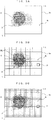
- the original image Ia is divided into square blocks having a predetermined size.
- reference sign P denotes one pixel.
- one block BL is a square area composed of a total of 16 pixels P, 4 pixels in each of X and Y directions.
- the size of the block BL is desirably set according to the size of the cell image C as an extraction object in the image.
- the block size of the block BL is preferably so selected that substantially one block enters the cell image C as the extraction object in the image.
- the size of the block BL is preferably such that a length of one side converted into a specimen size is about equal or slightly smaller than this diameter. From this, the size of one pixel P is preferably such that one side is 2.5 ⁇ m to 5 ⁇ m or slightly smaller.
- a resolution in imaging is, for example, 6400 dpi (dots per inch)
- the pixel size is about 4 ⁇ m.
- the resolution is 16000 dpi
- the pixel size is about 1.6 ⁇ m.
- 6400 dpi to 16000 dpi is preferable as a resolution necessary to obtain the size of the pixel P described above.
- these are values suitable to perform the area segmentation processing of this embodiment. It is fundamental to perform imaging at as high a resolution as possible at the time of imaging without limitation to this.
- an original image can be captured at a resolution of 32000 dpi (pixel size of 0.8 ⁇ m)
- four pixels in the original image Ia at the time of imaging is regarded as one pixel P in a pseudo manner and an average pixel value of those pixels is set as a pixel value of this pixel P.
- the pixel size (1.6 ⁇ m) suitable for the area segmentation processing can be obtained without reducing the resolution at the time of imaging.
- such a processing is referred to as a "resolution conversion".
- Whether or not the resolution conversion is necessary is determined by a relationship of the pixel size at the time of imaging and the size of the cell image C as a processing object. If the relationship of those is known in advance, whether or not the resolution conversion is necessary can be judged from that known relationship. Further, whether or not to perform the resolution conversion may be determined based on an instruction input from a user. If it is judged to be necessary, the resolution conversion is performed (Step S103).
- a square constituted by 4 pixels by 4 pixels in the image after the conversion is set as one block BL.
- a square constituted by 4 pixels by 4 pixels in the image at the time of capturing the original image Ia is set as one block BL. If the number of the pixels of one line is exactly divisible by the number 4 of the pixels of one side of one block in at least either one of X and Y directions, the pixels not included in the processing may be present in an end part of the original image. Further, the end part of the original image may be cut off in advance so that such fractions are not present.
- the average pixel value in the entire original image Ia is subtracted as the offset value from the pixel value of each pixel (Step S105).
- the pixel value is expressed, for example, as 8-bit data, each pixel can have a value in 256 levels from 0 to 255.
- By subtracting the average pixel value some pixels have a negative value as the pixel value.
- the positive and negative balance of each pixel value is improved by subtracting the average pixel value of the entire image from each pixel.
- a pixel value g(X, Y) of the image P after subtraction is expressed by the following (Equation 1).
- Equation 1 a pixel value g(X, Y) of the image P after subtraction is expressed by the following (Equation 1).
- the DCT computation is performed for each of the thus divided blocks (Step S106).
- An image content of each block is decomposed into a two-dimensional spatial frequency component in each of the X and Y directions by the DCT computation.
- the DCT computation processing is widely known as also utilized in the JPEG image compression processing. Thus, items to which the same way of thinking as the JPEG image compression processing can be applied are not described below.
- FIG. 4 is diagrams showing a concept of the DCT computation.
- the left diagram shows one block BL, which is a part of the original image and composed of (4 ⁇ 4) pixels. Small letters are used to express the position of each pixel in the block in such a manner as to be distinguished from a coordinate position in the original image, a horizontal-direction coordinate is an x coordinate, and a vertical-direction coordinate is a y coordinate.
- the DCT computation can be considered as a computation of obtaining a 4 ⁇ 4 DCT coefficient table T shown in the right diagram of FIG. 4 from the pixel value g(x, y) of each pixel in the block BL.
- a DCT coefficient C(u, v) indicating an intensity of each frequency component is expressed by the following (Equation 2).
- p u ⁇ 1 / 2
- u 0 1
- p v ⁇ 1 / 2
- v 0 1 , v ⁇ 0
- N denotes a block size.
- N 8 i.e. (8 ⁇ 8) pixels constitute one block.
- N 4 since (4 ⁇ 4) pixels constitute one block as described above. According to the knowledge of the inventors of this application, a better result is obtained in this processing method utilizing the DCT coefficient as a feature amount without aiming to compress/decompress an image if the block size is (4 ⁇ 4) pixels. Further, this can also reduce an amount of computation and is suitable for speed-up.
- a coefficient indicating a component having a frequency equal to or lower than a predetermined frequency e.g. a coefficient C(0, 0) of a direct-current component
- a total of the other coefficients is set as a high-frequency feature amount.
- the DCT coefficient can have either a positive or negative value. To avoid the offset of those values at the time of totaling, the total of the DCT coefficients may be obtained as the sum of absolute values of the respective DCT coefficients.
- Step S108 Whether each block is equivalent to the "cell image” or the "non-cell image” is determined based on the low-frequency feature amount and the high-frequency feature amount obtained in this way. This determination is made based on the position of the block in a two-dimensional feature amount space constituted by the low-frequency feature amounts and the high-frequency feature amounts. To make the determination, a determination criteria, specifically a range occupied by features of the "cell image" in the two-dimensional feature amount space, needs to be specified in advance.
- a range occupied by a cell cluster in a two-dimensional feature amount space can be specified in advance by collecting a multitude of images of typical cells imaged under the same conditions as case examples and using an appropriate machine learning algorithm. By doing so, whether or not a block corresponds to a cell or a non-cell can be determined based on whether or not feature amounts of the block selected from an unknown original image belongs to the cell cluster.
- FIG. 5 is a flow chart showing a processing of establishing the determination criteria.
- FIGS. 6A through 6C are diagrams illustrating instruction input modes in a processing process. This processing is to receive an instruction from an operator for a typical example having strong features of a cell image and a non-cell image, out of an obtained original image la, and specify a boundary between the cell image and the non-cell image in a two-dimensional feature amount space from the received information. This processing can be performed at an arbitrary timing until the classification of the blocks (Step S108) is started after the computer device 1 obtained the original image Ia (Step S101). The processing is realized by the CPU 10 executing the control program stored in the storage 15.
- the obtained original image Ia is displayed on the display unit 17 and presented to the operator (Step S201). Then, an instruction input from the operator designating a representative point belonging to a cell area and a representative point corresponding to a non-cell area in the displayed original image Ia is received (Step S202). Note that if the cell area and the non-cell area are clearly different in appearance, only the representative point belonging to the cell area may be designated.
- FIG. 6A For example, the operator is caused to continuously move a pointer in an area of the cell image C through a mouse operation or touch pen input. By doing so, a plurality of points on that trace can be obtained and collected as representative points of the cell image C.
- a white arrow in FIG. 6A indicates the pointer moving on a screen in association with the operation of a mouse or the like by a user.
- a rectangular area belonging to the cell image C, a rectangular area outside the cell image and the like may be designated as two-dimensional areas. If a debris image D and a background image B are present in the image, it is desirable to include both an area of the debris image D and an area of the background image B in designating the area outside the cell. By doing so, representative points extracted from the area outside the cell include both those having features of the debris image D and those having features of the background image B. Thus, information on the non-cell can be more strongly reflected in determining the boundary between the cell area and the non-cell area in the feature amount space.
- an area of the cell image C, an area of the debris image D and an area of the background image B may be respectively individually designated. Representative points selected from the thus designated ranges respectively form a cell cluster, a debris cluster and a background cluster in the feature amount space. Thus, not only the cell image and the non-cell image can be segmented, but also the area segmentation can be performed, for example, between the background image and the debris image.
- Step S203 an average pixel value in the entire original image Ia is subtracted from the pixel value of each pixel similarly to the area segmentation processing described above (Step S203).
- the DCT computation is performed (Step S204) and the low-frequency feature amount and the high-frequency feature amount are calculated from the DCT coefficient (Step S205) for each virtual block of the (4 ⁇ 4) pixel size including the representative point.
- Step S205 a distribution in the two-dimensional feature amount space when the blocks including the representative points are typical examples becomes clear. From that result, the boundary between a region of the "cell image” and a region of the "non-cell image" in the two-dimensional feature amount space can be specified (Step S206).
- FIGS. 7A and 7B are graphs showing examples of boundary specification methods in a feature amount space.
- the low-frequency feature amount and the high-frequency feature amount are obtained for each of several blocks including the representative points in those areas. If the respective blocks are plotted in the two-dimensional feature amount space, it is thought that two clusters, i.e. a cluster (cell cluster) C1 corresponding to the cell image C and a cluster (non-cell cluster) C2 corresponding to the non-cell, i.e. the background image B and the debris image D, are formed due to differences of image features of the cell image and the non-cell image as shown in FIG. 7A .
- Center-of-gravity points G1, G2 of these clusters C1, C2 can be respectively specified, and a perpendicular bisector L2 to a line segment L1 connecting these center-of-gravity points G1, G2 can be set as a boundary dividing the cell image and the non-cell image in the feature amount space.
- a perpendicular bisector L2 to a line segment L1 connecting these center-of-gravity points G1, G2 can be set as a boundary dividing the cell image and the non-cell image in the feature amount space.
- a cluster C1 corresponding to the cell image C, a cluster C3 corresponding to the background image B and a cluster C4 corresponding to the debris image D are formed in the feature amount space as shown in FIG. 7B .
- this curve L3 can be set as a boundary dividing the cell image and the non-cell image.
- an original image including a cell image is divided into a plurality of small blocks and a spatial frequency component of each block is obtained. Then, the block is classified according to a position occupied in a two-dimensional feature amount space by a set of a low-frequency feature amount (first feature amount) based on an intensity of a low frequency component and a high-frequency feature amount (second feature amount) based on an intensity of a high frequency component. More specifically, whether an image of the block corresponds to the cell or the non-cell other than the cell is determined based on whether or not this block belongs to the cell cluster in the two-dimensional feature amount space.
- first feature amount a low-frequency feature amount
- second feature amount high-frequency feature amount
- the low-frequency feature amount represents the brightness and a relatively simple structure of the block and the high-frequency feature amount represents a fine texture in the block.
- the invention is not limited to the embodiment described above and various changes other than the aforementioned ones can be made without departing from the gist of the invention.
- the original image is segmented into the cell image and the non-cell image block by block.
- the block boundary is automatically established and does not necessarily coincide with the boundary between the cell image and the non-cell image in the original image.
- the original image may be segmented, for example, in combination with the known contour extraction processing.
- the position of the boundary between the cell area and the non-cell area specified block by block as described above may be corrected based on a result of the contour extraction processing.
- the processing of specifying the boundary of the cell cluster in the two-dimensional feature amount space in the above embodiment is merely illustrative. Besides this, various clustering methods can be applied. Further, the method for collecting the typical examples of the cell image and the non-cell image is also not limited to the above method.
- the direct-current component C(0, 0) of the DCT coefficient is used for the low-frequency feature amount and the sum of the absolute values of the other DCT coefficients is used for the high-frequency feature amount. That is, the DCT coefficient of the direct-current component is set as the low-frequency feature amount and the sum of the absolute values of the DCT coefficients of the alternating-current components is set as the high-frequency feature amount.
- the frequency for distinguishing the low-frequency feature amount and the high-frequency feature amount is not limited to this and may be a relatively low alternating-current frequency. Further, if there is a method for appropriately obtaining the spatial frequency component besides the DCT computation, such a method may be utilized.
- this processing function may be, for example, incorporated into the imaging device as described above. Further, it is also possible to expand functions by additionally mounting a program for performing the area segmentation processing of this embodiment in an existing imaging device.
- an intensity of a direct-current component out of spatial frequency components can be set as the first feature amount and a total of intensities of alternating-current components can be set as the second feature amount.
- the direct-current component represents an average brightness of a block and the alternating-current components represent a brightness change mode, i.e. a texture, in the block.
- the image is segmented based on the feature amounts indicating the brightness and the texture in the block, and area segmentation having a higher accuracy than a mere binarization processing or contour extraction processing is possible.
- the two-dimensional discrete cosine transform can be performed for each block based on the pixel values of the pixels included in this block, and the intensity of each frequency component can be obtained as a discrete cosine transform coefficient of this frequency component.
- Such a processing is also utilized in the JPEG image compression processing and a computation algorithm is already established. Thus, this can be also applied to the invention.
- the two-dimensional discrete cosine transform can be performed based on values obtained by subtracting an average pixel value of the entire original image from the pixel values of the respective pixels. Since a distribution range of pixel values is small in an image obtained by imaging a cell close to transparent, a level shift for discrete cosine transform computation is preferably performed using the average pixel value of the entire original image.
- a total of intensities of a plurality of frequency components can be obtained as the sum of absolute values of discrete cosine transform coefficients of the respective frequency components. Since the discrete cosine transform coefficients can have either a positive or negative value, the respective frequency components may be offset and a good result may not be obtained by simple totaling. By taking the sum of the absolute values, this problem can be solved.
- each block can be a square, the size of one side of which is equivalent to 4 pixels.
- the block size is 8 pixels in the JPEG image compression.
- the block size is set at 4 pixels in the invention not aiming to compress/decompress an image.
- a preferable pixel size at the time of computation depends, for example, on the size of an object in an image such as a cell image.
- the pixel size for this purpose does not necessarily coincide with a preferable pixel size at the time of imaging.
- the pixel size can be individually optimized by converting the pixel size.
- the cell image and another area other than the cell image can be stably divided even if the type of the cell and imaging conditions are not fixed.
- the original image can be an image obtained by bright field imaging a cell. Since the cell is generally close to transparent and has a refractive index not much different from that of a culture medium, it is difficult to visually distinguish a cell image and a non-cell image in an image obtained by bright field imaging.
- a cell area and other area(s) in the image can be satisfactorily and stably divided.
- the invention is applicable in biochemical and medical fields to image a cell and evaluate an image, and particularly preferable in technical fields requiring imaging free from such a processing as to damage a cultured cell.
Landscapes
- Engineering & Computer Science (AREA)
- Physics & Mathematics (AREA)
- General Physics & Mathematics (AREA)
- Theoretical Computer Science (AREA)
- Health & Medical Sciences (AREA)
- Life Sciences & Earth Sciences (AREA)
- Multimedia (AREA)
- Biomedical Technology (AREA)
- Computer Vision & Pattern Recognition (AREA)
- Molecular Biology (AREA)
- General Health & Medical Sciences (AREA)
- Chemical & Material Sciences (AREA)
- Data Mining & Analysis (AREA)
- Software Systems (AREA)
- Analytical Chemistry (AREA)
- Biochemistry (AREA)
- Pathology (AREA)
- Immunology (AREA)
- Medicinal Chemistry (AREA)
- Optics & Photonics (AREA)
- Biophysics (AREA)
- Hematology (AREA)
- Urology & Nephrology (AREA)
- Food Science & Technology (AREA)
- Bioinformatics & Cheminformatics (AREA)
- Bioinformatics & Computational Biology (AREA)
- Artificial Intelligence (AREA)
- General Engineering & Computer Science (AREA)
- Evolutionary Biology (AREA)
- Evolutionary Computation (AREA)
- Image Analysis (AREA)
- Investigating Or Analysing Biological Materials (AREA)
Applications Claiming Priority (2)
| Application Number | Priority Date | Filing Date | Title |
|---|---|---|---|
| JP2018050932A JP7079631B2 (ja) | 2018-03-19 | 2018-03-19 | 画像処理方法、コンピュータプログラムおよび記録媒体 |
| PCT/JP2018/043983 WO2019181072A1 (fr) | 2018-03-19 | 2018-11-29 | Procédé de traitement d'image, programme informatique et support d'enregistrement |
Publications (2)
| Publication Number | Publication Date |
|---|---|
| EP3770853A1 true EP3770853A1 (fr) | 2021-01-27 |
| EP3770853A4 EP3770853A4 (fr) | 2021-12-15 |
Family
ID=67987050
Family Applications (1)
| Application Number | Title | Priority Date | Filing Date |
|---|---|---|---|
| EP18911181.8A Pending EP3770853A4 (fr) | 2018-03-19 | 2018-11-29 | Procédé de traitement d'image, programme informatique et support d'enregistrement |
Country Status (4)
| Country | Link |
|---|---|
| US (1) | US11430130B2 (fr) |
| EP (1) | EP3770853A4 (fr) |
| JP (1) | JP7079631B2 (fr) |
| WO (1) | WO2019181072A1 (fr) |
Families Citing this family (2)
| Publication number | Priority date | Publication date | Assignee | Title |
|---|---|---|---|---|
| JP2021173734A (ja) * | 2020-04-30 | 2021-11-01 | ソニーグループ株式会社 | 生成装置、生成方法、生成プログラム及び診断支援システム |
| JP2022007281A (ja) * | 2020-06-26 | 2022-01-13 | ソニーグループ株式会社 | 画像処理装置、画像処理方法、画像処理プログラム及び診断支援システム |
Family Cites Families (11)
| Publication number | Priority date | Publication date | Assignee | Title |
|---|---|---|---|---|
| JPH0216682A (ja) * | 1988-07-04 | 1990-01-19 | Sumitomo Electric Ind Ltd | 細胞増殖状態のモニタ方法及びそのモニタ装置 |
| JP4107544B2 (ja) | 2000-10-23 | 2008-06-25 | 三菱電機株式会社 | 画像信号の再符号化装置 |
| JP2004229097A (ja) | 2003-01-24 | 2004-08-12 | Ricoh Co Ltd | 画像処理装置、プログラム及び記憶媒体 |
| JP4100627B2 (ja) | 2004-02-27 | 2008-06-11 | 株式会社リコー | 画像処理装置、画像処理方法、プログラム及び情報記録媒体 |
| JP2005250778A (ja) | 2004-03-03 | 2005-09-15 | Seiko Epson Corp | 画像の天地方向判定 |
| JP4772839B2 (ja) | 2008-08-13 | 2011-09-14 | 株式会社エヌ・ティ・ティ・ドコモ | 画像識別方法および撮像装置 |
| JP5601133B2 (ja) | 2010-10-01 | 2014-10-08 | 大日本印刷株式会社 | 画像処理装置、画像処理方法、プログラムおよび記憶媒体 |
| JP6000699B2 (ja) | 2012-07-05 | 2016-10-05 | オリンパス株式会社 | 細胞分裂過程追跡装置、及び細胞分裂過程追跡プログラム |
| JP6333145B2 (ja) | 2014-09-30 | 2018-05-30 | 株式会社Screenホールディングス | 画像処理方法および画像処理装置 |
| WO2016076515A1 (fr) * | 2014-11-13 | 2016-05-19 | 삼성전자 주식회사 | Procédé et dispositif pour la génération de métadonnées comprenant des informations de caractéristiques de fréquences d'image |
| WO2017169196A1 (fr) * | 2016-03-28 | 2017-10-05 | 富士フイルム株式会社 | Procédé de criblage de cellules |
-
2018
- 2018-03-19 JP JP2018050932A patent/JP7079631B2/ja active Active
- 2018-11-29 WO PCT/JP2018/043983 patent/WO2019181072A1/fr unknown
- 2018-11-29 EP EP18911181.8A patent/EP3770853A4/fr active Pending
- 2018-11-29 US US16/979,928 patent/US11430130B2/en active Active
Also Published As
| Publication number | Publication date |
|---|---|
| US11430130B2 (en) | 2022-08-30 |
| JP7079631B2 (ja) | 2022-06-02 |
| EP3770853A4 (fr) | 2021-12-15 |
| US20210012509A1 (en) | 2021-01-14 |
| JP2019164450A (ja) | 2019-09-26 |
| WO2019181072A1 (fr) | 2019-09-26 |
Similar Documents
| Publication | Publication Date | Title |
|---|---|---|
| US11636696B2 (en) | Identifying regions of interest from whole slide images | |
| EP3788591B1 (fr) | Prédiction d'erreur de classificateur à apprentissage automatique pondérée par la mise au point pour images de lames de microscope | |
| WO2021139258A1 (fr) | Procédé et appareil de reconnaissance et de comptage de cellules sur la base de la reconnaissance d'images et dispositif informatique | |
| US10168526B2 (en) | Cell contour formation apparatus and method of the same, and non-transitory computer readable storage medium storing a cell contour formation program | |
| Schoening et al. | RecoMIA—Recommendations for marine image annotation: Lessons learned and future directions | |
| US10121245B2 (en) | Identification of inflammation in tissue images | |
| KR100836740B1 (ko) | 영상 데이터 처리 방법 및 그에 따른 시스템 | |
| CN111598869B (zh) | 一种对显示屏幕的Mura进行检测的方法、设备及存储介质 | |
| EP3624053B1 (fr) | Dispositif d'analyse d'image | |
| CN112132166A (zh) | 一种数字细胞病理图像智能分析方法、系统及装置 | |
| US11430130B2 (en) | Image processing method and computer-readable recording medium having recorded thereon image processing program | |
| CN113592792A (zh) | 堆石图像粒径识别方法、装置、电子设备及存储介质 | |
| Lee et al. | Image analysis using machine learning for automated detection of hemoglobin H inclusions in blood smears-a method for morphologic detection of rare cells | |
| EP3611695A1 (fr) | Génération de données d'annotation d'images de tissus | |
| Salih et al. | Adaptive local exposure based region determination for non-uniform illumination and low contrast images | |
| CN115908363A (zh) | 肿瘤细胞统计方法、装置、设备和存储介质 | |
| EP3588435B1 (fr) | Procédé de traitement d'images, programme informatique et support d'enregistrement | |
| Meruvia-Pastor et al. | Estimating cell count and distribution in labeled histological samples using incremental cell search | |
| CN113470028A (zh) | 染色体核型图像质量评估方法、染色体分析仪和存储介质 | |
| Tan et al. | Simple Landscapes Analysis for Relevant Regions Detection in Breast Carcinoma Histopathological Images | |
| CN113724267B (zh) | 一种乳腺超声图像肿瘤分割方法及装置 | |
| CN116433674B (zh) | 半导体硅晶圆检测方法、装置、计算机设备及介质 | |
| WO2024062953A1 (fr) | Procédé et programme de traitement d'image | |
| EP4369297A1 (fr) | Procédé et dispositif pour produire des informations relatives à une image de diapositive pathologique | |
| CN111369491B (zh) | 图像污点检测方法、装置、系统及存储介质 |
Legal Events
| Date | Code | Title | Description |
|---|---|---|---|
| STAA | Information on the status of an ep patent application or granted ep patent |
Free format text: STATUS: THE INTERNATIONAL PUBLICATION HAS BEEN MADE |
|
| PUAI | Public reference made under article 153(3) epc to a published international application that has entered the european phase |
Free format text: ORIGINAL CODE: 0009012 |
|
| STAA | Information on the status of an ep patent application or granted ep patent |
Free format text: STATUS: REQUEST FOR EXAMINATION WAS MADE |
|
| 17P | Request for examination filed |
Effective date: 20200909 |
|
| AK | Designated contracting states |
Kind code of ref document: A1 Designated state(s): AL AT BE BG CH CY CZ DE DK EE ES FI FR GB GR HR HU IE IS IT LI LT LU LV MC MK MT NL NO PL PT RO RS SE SI SK SM TR |
|
| AX | Request for extension of the european patent |
Extension state: BA ME |
|
| DAV | Request for validation of the european patent (deleted) | ||
| DAX | Request for extension of the european patent (deleted) | ||
| A4 | Supplementary search report drawn up and despatched |
Effective date: 20211112 |
|
| RIC1 | Information provided on ipc code assigned before grant |
Ipc: G06T 7/168 20170101ALI20211108BHEP Ipc: G06T 7/11 20170101ALI20211108BHEP Ipc: G06T 7/00 20170101ALI20211108BHEP Ipc: G06T 7/194 20170101AFI20211108BHEP |
|
| GRAP | Despatch of communication of intention to grant a patent |
Free format text: ORIGINAL CODE: EPIDOSNIGR1 |
|
| STAA | Information on the status of an ep patent application or granted ep patent |
Free format text: STATUS: GRANT OF PATENT IS INTENDED |
|
| INTG | Intention to grant announced |
Effective date: 20240212 |
|
| GRAJ | Information related to disapproval of communication of intention to grant by the applicant or resumption of examination proceedings by the epo deleted |
Free format text: ORIGINAL CODE: EPIDOSDIGR1 |
|
| STAA | Information on the status of an ep patent application or granted ep patent |
Free format text: STATUS: REQUEST FOR EXAMINATION WAS MADE |
|
| P01 | Opt-out of the competence of the unified patent court (upc) registered |
Effective date: 20240412 |