EP3770646A1 - Lichtvorhang - Google Patents
Lichtvorhang Download PDFInfo
- Publication number
- EP3770646A1 EP3770646A1 EP20167898.4A EP20167898A EP3770646A1 EP 3770646 A1 EP3770646 A1 EP 3770646A1 EP 20167898 A EP20167898 A EP 20167898A EP 3770646 A1 EP3770646 A1 EP 3770646A1
- Authority
- EP
- European Patent Office
- Prior art keywords
- potential
- light curtain
- receiver
- receivers
- power supply
- Prior art date
- Legal status (The legal status is an assumption and is not a legal conclusion. Google has not performed a legal analysis and makes no representation as to the accuracy of the status listed.)
- Granted
Links
Images

Classifications
-
- G—PHYSICS
- G01—MEASURING; TESTING
- G01V—GEOPHYSICS; GRAVITATIONAL MEASUREMENTS; DETECTING MASSES OR OBJECTS; TAGS
- G01V3/00—Electric or magnetic prospecting or detecting; Measuring magnetic field characteristics of the earth, e.g. declination, deviation
- G01V3/18—Electric or magnetic prospecting or detecting; Measuring magnetic field characteristics of the earth, e.g. declination, deviation specially adapted for well-logging
- G01V3/20—Electric or magnetic prospecting or detecting; Measuring magnetic field characteristics of the earth, e.g. declination, deviation specially adapted for well-logging operating with propagation of electric current
Definitions
- the invention relates to a light curtain according to the preamble of claim 1.
- Such a light curtain is used to monitor objects in a monitored area.
- the light curtain is designed as a safety light curtain that is used in the field of safety technology for monitoring danger areas.
- the light curtain comprises an arrangement of transmitters which are accommodated in the housing of a transmitter unit.
- an arrangement of receivers is provided, which are accommodated in a housing of a receiver unit.
- the transmitter and receiver units are arranged on opposite edges of the monitoring area.
- the light curtain is operated in such a way that the beam axes, that is to say the transmitters and receivers of the individual beam axes, are activated cyclically one after the other.
- the monitoring area is free, the light beams emitted by a transmitter are directed to an assigned receiver.
- the transmitter and the assigned receiver form a beam axis.
- the received signals of the receivers are evaluated in the evaluation unit and, depending on this, a binary switching signal is generated as the object detection signal, the switching states of which indicate whether or not an object is in the monitoring area.
- Object engagement occurs when at least one beam axis is interrupted by an object.
- the transmitters can be activated individually or in groups by means of a first control circuit without a current-limiting resistor in their current path.
- the transmission current is specified centrally and can be individually adjusted for the individual transmitters.
- the receivers form at least one receiver cascade.
- the receivers can be activated individually or in groups by means of a second control circuit.
- the received signals are fed to a common group amplifier per receiver without individual preamplification, analog switches and / or impedance converters.
- the invention is based on the object of improving a light curtain of the type mentioned in terms of its functionality.
- the invention relates to a light curtain with a transmitter unit which has a series arrangement of transmitters emitting light beams, with a receiver unit which has a series arrangement of light beam receiving receivers and with an evaluation unit in which an object detection signal is generated as a function of received signals from the receiver.
- An arrangement with amplifiers is assigned to the receivers, so that the individual receivers are assigned control elements which are controlled by control means.
- the amplifier or amplifiers draw their voltage supply from a potential P1 and their ground reference from a potential P2.
- the control elements obtain their voltage supply from a potential P3 and their ground reference from a potential P4.
- the potential P1 is higher than the potential P3.
- the potential 3 is higher than the potential 2.
- the potential P2 is higher than the potential P 4.
- An essential aspect of the invention is that only positive voltages are used to supply voltage to the electronic components on the receiver side. This leads to an increased functionality of the light curtain according to the invention compared to known light curtains such as, for example, in FIG EP 2 444 825 A2 describes where negative auxiliary voltages are used, in particular to supply voltage to control flip-flops for controlling individual receivers of the light curtain.
- the amplifier arrangement receives a high operating voltage and the receivers, which are preferably formed by photodiodes, also receive high blocking voltages.
- Another advantage of the invention is that the positive voltages required for the voltage supply can be implemented in a structurally simple manner using power supply units.
- the power supplies are made up of electrical switching power supplies such as linear power supplies.
- the potentials P1, P2, P3 are advantageously generated with a power supply unit.
- the power supplies can all be directly connected to a power supply unit.
- the power supply units are cascaded.
- the power supply units are connected individually or jointly to a supply unit with a higher voltage than the potentials P1, P2, P3.
- the arrangement of amplifiers has at least one preamplifier, which draws its voltage supply from the potential P1 and its ground reference from the potential 2.
- only one preamplifier can be provided.
- a preamplifier is advantageously assigned to each receiver.
- the collective amplifier By supplying the collective amplifier with a positive voltage, it receives a high operating voltage, which means that it has a high dynamic range when amplifying the received signals of the individual receivers, which is an essential prerequisite for high detection sensitivity in object detection with the receivers.
- the control and activation of the receiver takes place via the control means.
- the control elements can be addressed by means of the control means.
- a receiver is activated when the associated control element is addressed.
- the receivers are activated, in particular by optical synchronization, together with assigned transmitters of the transmitter unit in order to carry out object detections in a monitoring area.
- the transmitter units and the receiver units are arranged on opposite edges of the surveillance area.
- a transmitter with an assigned receiver advantageously forms a beam axis in each case, the spatial arrangement being such that the light beams of a transmitter reach the receiver of this beam axis unhindered in a free monitoring area.
- at least one beam axis is interrupted, which is recognized in the evaluation unit by a threshold evaluation of the received signals of the receivers, so that a corresponding object detection signal is generated in the evaluation unit.
- the transmitters and receivers are activated cyclically for continuous object detection in the surveillance area.
- the receivers can be activated individually or in groups within a cycle.
- the control means can be formed by a logic circuit or a processor.
- the control elements are advantageously designed as control flip-flops.
- the receivers consist of photodiodes, each photodiode advantageously being assigned a decoupling diode.
- the control via the control means takes place in such a way that the associated photodiode is activated by addressing a control element and the associated decoupling diode is separated.
- the photodiode is then switched to the blocking mode and the decoupling diode switches the photocurrent of the photodiode through to the amplifier, in particular to the preamplifier.
- the photodiode is switched in the forward direction (photo element operation) and the decoupling diode separates the photodiode from the preamplifier.
- the decoupling of preamplifiers brought about by the decoupling diodes also ensures that no capacitively coupled interfering signals reach the preamplifier, as a result of which signal falsifications and the resulting false detections are avoided.
- An object detection signal is generated in the evaluation unit as a function of the received signals from the receiver.
- the object detection signal is advantageously designed as a binary switching signal, the switching states of which indicate whether or not an object is located in the monitoring area.
- the light curtain is designed as a safety light curtain for use in safety-related applications, in particular in the area of personal protection.
- the safety light curtain has a fail-safe structure, which is achieved in particular by a redundant, two-channel evaluation unit in the form of two computer units that monitor each other cyclically.
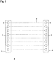
- FIG. 1 shows the basic structure of an embodiment of the light curtain 1 according to the invention.
- the light curtain 1 comprises a transmitter unit 2, in the housing of which a series arrangement of transmitters 4 emitting light beams 3 in the form of transmitter diodes is arranged.
- the transmitting diodes 4 are formed by light emitting diodes or the like.
- the light curtain 1 also has a receiver unit 5, in the housing of which a series arrangement of receivers 6 receiving light beams 3 is provided in the form of receiving diodes.
- the receiving diodes 6 are formed by photodiodes 61, 62 .... In principle, the receiving diodes can also be formed by photo PIN diodes.
- the transmitter unit 2 and the receiver unit 5 are arranged on the opposite edges of a monitoring area. When the monitoring area is free, the light beams 3 emitted by one transmitter 4 each strike an associated opposite receiver 6. A transmitter 4 and the associated receiver 6 each form a beam axis.
- the transmitter operation is controlled and evaluated by a control unit 7 in the transmitter unit 2.
- the receiver operation is controlled and evaluated by a control and evaluation unit 8 in the receiver unit 5.
- the transmitters 4 and receivers 6 of the individual beam axes are activated cyclically one by one or several in succession by optical synchronization of the light curtain 1.
- the control and evaluation unit 8 has an evaluation unit.
- the received signals of the photodiodes 61, 62 are evaluated in the evaluation unit in order to generate a binary switching signal as the object detection signal.
- the first switching state corresponds to an object message, the second switching state to a free protective field.
- the light curtain 1 forms a safety sensor for use in the field of safety technology.
- the light curtain 1 has a fail-safe Build on.
- the evaluation unit has a multi-channel, redundant structure, for example in the form of two computer units that monitor each other cyclically.
- FIG. 2 shows the structure of a control circuit as part of the control and evaluation unit 8, the control circuit being used to control the operation of the receivers 6 of the light curtain 1.
- the receivers 6 are formed by photodiodes 61, 62, which are designated by the reference numerals 61, 62, ....
- each photodiode 61, 62 is assigned a working resistor 71, 72 and a decoupling diode 81, 82.
- Control means 9 and control elements in the form of control flip-flops 10.1, 10.2 are provided to control the receiver 6.
- the control means 9 can be formed by a logic circuit or a processor.
- a control flip-flop 10.1, 10.2 is assigned to each receiver 6, that is to say to each photodiode 61, 62 with an associated working resistor 71, 72 and decoupling diode 81, 82.
- the control flip-flops 10.1, 10.2 are controlled with the control means 9 via a clock line 12 and a control line 11.
- a common preamplifier 13 is provided for the individual photodiodes 61, 62 for preamplifying the received signals of all photodiodes 61, 62.
- a preamplifier 13 can also be assigned to each photodiode 61, 62.
- the received signals preamplified in the preamplifier 13 are fed to a collecting amplifier 14, the received signals amplified there again are fed to the control means 9 and read from there into the evaluation unit.
- Three power supply units 15a, 15b, 15c are provided for supplying voltage to the components of the control circuit.
- the power supply units can be identical or different.
- the power supplies are designed as electronic switching power supplies or linear voltage regulators.
- the first power supply unit 15a generates a potential P1 as the supply voltage.
- the second power supply unit 15b generates a potential P3 as the supply voltage.
- the third power supply unit generates a potential P2 as the supply voltage.
- the preamplifier 13 draws its voltage supply from the potential P1 and its ground reference from the potential P2.
- the collective amplifier 14 draws a voltage supply from the potential P1 and its ground reference from the potential P4.
- the control flip-flops 10.1, 10.2 draw their voltage supply from the potential P3 and their ground reference from the potential P4.
- the control means 9 draw their voltage supply from the potential P2 and their ground reference from the potential P4.
- the power supply according to the invention supplies all components of the control circuit with positive voltages. A high dynamic range of the collecting amplifier 14 is thereby obtained.
- the photodiodes 61, 62 receive a high reverse voltage when they are activated. As a result, a high detection sensitivity is obtained when detecting objects.
- the individual control flip-flops 10.1, 10.2 are addressed by the control means 9, whereby the control flip-flops 10.1, 10.2 assigned to one addressed control flip-flops 10.1, 10.2 is activated.
- the associated photodiode 61, 62 is switched to the inactive output of the control flip-flop 10.1, 10.2 Locking operation switched.
- the decoupling diode switches the photocurrent of the photodiode 61, 62 through to the preamplifier 13.
- the photodiodes 61, 62 can be activated individually by addressing. Photodiodes 61, 62 that are not activated are controlled by preamplifiers 13 via the decoupling diode. A capacitive coupling of interference signals into the preamplifier 13 is thereby also avoided.
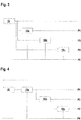
- FIGS. 3 and 4 show exemplary embodiments of connections of the power supply units 15a-c to a voltage supply unit 16.
- a cascaded arrangement is provided such that only the power supply unit 15a is connected directly to the voltage supply unit 16.
- the power supply unit 15c is connected to the power supply unit 15b, the power supply unit 15b to the power supply unit 15a, so that the power supply units 15b, 15c are indirectly connected to the voltage supply unit 16 via further power supply units 15a, 15b.
Landscapes
- Life Sciences & Earth Sciences (AREA)
- Engineering & Computer Science (AREA)
- Environmental & Geological Engineering (AREA)
- Geology (AREA)
- Remote Sensing (AREA)
- Physics & Mathematics (AREA)
- General Life Sciences & Earth Sciences (AREA)
- General Physics & Mathematics (AREA)
- Geophysics (AREA)
- Electronic Switches (AREA)
Abstract
Description
- Die Erfindung betrifft einen Lichtvorhang gemäß dem Oberbegriff des Anspruchs 1.
- Ein derartiger Lichtvorhang dient zur Überwachung von Objekten in einem Überwachungsbereich. Insbesondere ist der Lichtvorhang als Sicherheits-Lichtvorhang ausgebildet, der im Bereich der Sicherheitstechnik zur Überwachung von Gefahrenbereichen eingesetzt wird. Der Lichtvorhang umfasst eine Anordnung von Sendern die im Gehäuse einer Sendereinheit untergebracht sind. Weiterhin ist eine Anordnung von Empfängern vorgesehen, die in einem Gehäuse einer Empfängereinheit untergebracht sind. Die Sender- und Empfängereinheiten sind an gegenüberliegenden Rändern des Überwachungsbereichs angeordnet. Der Betrieb des Lichtvorhangs erfolgt derart, dass die Strahlachsen, das heißt die Sender und Empfänger der einzelnen Strahlachsen, zyklisch einzeln nacheinander aktiviert werden. Bei freiem Überwachungsbereich sind die von einem Sender emittierten Lichtstrahlen auf einen zugeordneten Empfänger geführt. Der Sender und der zugeordnete Empfänger bilden eine Strahlachse. Zur Objektdetektion werden in der Auswerteeinheit die Empfangssignale der Empfänger ausgewertet und in Abhängigkeit hiervon als Objektfeststellungssignal ein binäres Schaltsignal generiert, dessen Schaltzustände angeben, ob sich ein Objekt im Überwachungsbereich befindet oder nicht. Ein Objekteingriff liegt vor, wenn wenigstens eine Strahlachse durch ein Objekt unterbrochen ist.
- Aus der
EP 2 444 825 A2 ist ein Lichtvorhang bekannt, bei welchem Sender eine Senderkaskade bilden. - Die Sender sind mittels einer ersten Ansteuerschaltung ohne strombegrenzenden Widerstand in deren Strompfad direkt einzeln oder zu mehreren aktivierbar. Der Sendestrom wird zentral vorgegeben und ist für die einzelnen Sender individuell anpassbar. Die Empfänger bilden wenigstens eine Empfängerkaskade. Die Empfänger sind mittels einer zweiten Ansteuerschaltung einzeln oder zu mehreren aktivierbar. Die Empfangssignale werden ohne einzelne Vorverstärkung, Analogschalter und/oder Impedanzwandler pro Empfänger einem gemeinsamen Gruppenverstärker zugeführt.
- Der Erfindung liegt die Aufgabe zugrunde, einen Lichtvorhang der eingangsgenannten Art hinsichtlich seiner Funktionalität zu verbessern.
- Zur Lösung dieser Aufgabe sind die Merkmale des Anspruchs 1 vorgesehen. Vorteilhafte Ausführungsformen und zweckmäßige Weiterbildungen der Erfindung sind in den abhängigen Ansprüchen beschrieben.
- Die Erfindung betrifft einen Lichtvorhang mit einer Sendereinheit, welche eine Reihenanordnung von Lichtstrahlen emittierenden Sendern aufweist, mit einer Empfängereinheit, welche eine Reihenanordnung von Lichtstrahlen empfangenden Empfängern aufweist und mit einer Auswerteeinheit, in welcher in Abhängigkeit von Empfangssignalen der Empfänger ein Objektfeststellungssignal generiert wird. Den Empfängern ist eine Anordnung mit Verstärkern zugeordnet, dass den einzelnen Empfängern Ansteuerelemente zugeordnet sind, die von Steuermitteln gesteuert sind. Der oder die Verstärker beziehen ihre Spannungsversorgung aus einem Potential P1 und ihren Massebezug aus einem Potential P2. Die Ansteuerelemente beziehen ihre Spannungsversorgung aus einem Potential P3 und ihren Massebezug aus einem Potential P4. Das Potential P1 ist höher als das Potential P3. Das Potential 3 ist höher als das Potential 2. Das Potential P2 ist höher als das Potential P 4.
- Ein wesentlicher Aspekt der Erfindung besteht darin, dass zur Spannungsversorgung der empfangsseitigen elektronischen Bauelemente nur positive Spannungen eingesetzt werden. Dies führt zu einer erhöhten Funktionalität des erfindungsgemäßen Lichtvorhangs im Vergleich zu bekannten Lichtvorhängen wie zum Beispiel in der
EP 2 444 825 A2 beschrieben, wo negative Hilfsspannungen verwendet werden, insbesondere zur Spannungsversorgung von Ansteuer-Flip-Flops zur Ansteuerung einzelner Empfänger des Lichtvorhangs. - Dadurch, dass bei dem erfindungsgemäßen Lichtvorhang die Spannungsversorgung von empfangsseitigen elektronischen Komponenten nur mit positiven Spannungen erfolgt, erhält die Anordnung der Verstärker eine hohe Betriebsspannung und auch die vorzugsweise von Fotodioden gebildeten Empfänger erhalten hohe Sperrspannungen.
- Die Verstärker erhalten dadurch einen höheren Dynamikbereich und die Nachweisempfindlichkeit bei der Objektdetektion mit den Empfängern wird durch die hohen Sperrspannungen der Fotodioden erhöht.
- Ein weiterer Vorteil der Erfindung besteht darin, dass sich die zur Spannungsversorgung benötigten positiven Spannungen konstruktiv einfach durch Netzteile realisieren lassen.
- Die Netzteile sind von elektrischen Schaltnetzteilen wie zum Beispiel Linearnetzteilen gebildet.
- Vorteilhaft werden dabei die Potentiale P1, P2, P3 jeweils mit einem Netzteil generiert.
- Um die Netzteile selbst mit Spannung zu versorgen, können diese an eine Spannungsversorgungseinheit angeschlossen sein.
- Die Netzteile können alle direkt an eine Spannungsversorgungseinheit sein. Alternativ sind die Netzteile kaskadiert angeordnet.
- Gemäß einer weiteren Ausgestaltung sind die Netzteile einzeln oder gemeinsam an ein Versorgungs-Netzteil mit höherer Spannung als die Potentiale P1, P2, P3 angeschlossen.
- Gemäß einer vorteilhaften Ausführungsform weist die Anordnung von Verstärkern wenigstens einen Vorverstärker auf, welcher seine Spannungsversorgung aus dem Potential P1 und seinen Massebezug aus dem Potential 2 bezieht.
- Prinzipiell kann nur ein Vorverstärker vorgesehen sein.
- Alternativ ist nur ein gemeinsamer Vorverstärker für alle Empfänger vorgesehen.
- Vorteilhaft ist jedem Empfänger ein Vorverstärker zugeordnet.
- Durch die Spannungsversorgung des Sammelverstärkers mit einer positiven Spannung erhält dieser einer hohe Betriebsspannung, wodurch dieser einen hohen Dynamikbereich bei der Verstärkung der Empfangssignale der einzelnen Empfänger hat, was eine wesentliche Voraussetzung für eine hohe Nachweisempfindlichkeit bei den Objektdetektionen mit den Empfängern ist.
- Die Ansteuerung und Aktivierung der Empfänger erfolgt über die Steuermittel. Dabei sind die Ansteuerelemente mittels der Steuermittel adressierbar. Ein Empfänger ist dann aktiviert, wenn das zugehörige Ansteuerelement adressiert ist.
- Die Empfänger werden, insbesondere durch eine optische Synchronisierung, zusammen mit zugeordneten Sendern der Sendereinheit aktiviert um Objektdetektionen in einem Überwachungsbereich durchzuführen.
- Generell sind dabei die Sendereinheiten und die Empfängereinheiten an gegenüberliegenden Rändern des Überwachungsbereichs angeordnet.
- Dabei bildet vorteilhaft jeweils ein Sender mit einem zugeordneten Empfänger eine Strahlachse, wobei die räumliche Anordnung derart ist, dass bei einem freien Überwachungsbereich die Lichtstrahlen eines Senders ungehindert zum Empfänger dieser Strahlachse gelangen. Bei einem Objekteingriff im Überwachungsbereich wird wenigstens eine Strahlachse unterbrochen, was in der Auswerteeinheit durch eine Schwellwertbewertung der Empfangssignale der Empfänger erkannt wird, so dass in der Auswerteeinheit ein entsprechendes Objektfeststellungssignal generiert wird.
- Für eine fortlaufende Objektdetektion im Überwachungsbereich werden die Sender und Empfänger zyklisch aktiviert.
- Je nach Betrieb der Steuermittel können dabei die Empfänger innerhalb eines Zyklus einzeln oder in Gruppen aktiviert werden.
- Die Steuermittel können von einer Logikschaltung oder einem Prozessor gebildet sein. Die Ansteuerelemente sind vorteilhaft als Ansteuer-Flip-Flops ausgebildet.
- Die Empfänger bestehen aus Fotodioden, wobei vorteilhaft jeder Fotodiode eine Entkopplungsdiode zugeordnet ist.
- Die Ansteuerung über die Steuermittel erfolgt derart, dass durch eine Adressierung eines Ansteuerelements die zugehörige Fotodiode aktiviert und die zugehörige Entkopplungsdiode separiert ist.
- Die Fotodiode ist dann in den Sperrbetrieb geschaltet und die Entkopplungsdiode schaltet den Fotostrom der Fotodiode zum Verstärker, insbesondere zum Vorverstärker durch.
- Ist dagegen ein Empfänger nicht adressiert, ist die Fotodiode in Durchlassrichtung (Fotoelementbetrieb) geschaltet und die Entkopplungsdiode trennt die Fotodiode vom Vorverstärker.
- Dadurch ist gewährleistet, dass nur die Fotoströme der adressierten Empfänger zum Vorverstärker gelangen, dort verstärkt werden und dann der Auswerteeinheit zur Auswertung zugeführt werden.
- Durch die mit den Entkopplungsdioden bewirkten Entkopplungen von Vorverstärkern ist weiterhin gewährleistet, dass keine kapazitiv eingekoppelten Störsignale zum Vorverstärker gelangen, wodurch Signalverfälschungen und dadurch bedingt Fehldetektionen vermieden werden.
- In der Auswerteeinheit wird abhängig von den Empfangssignalen der Empfänger ein Objektfeststellungssignal generiert. Das Objektfeststellungssignal ist vorteilhaft als binäres Schaltsignal ausgebildet, dessen Schaltzustände angeben, ob sich ein Objekt im Überwachungsbereich befindet oder nicht.
- Für den Einsatz in sicherheitstechnischen Applikationen, insbesondere im Bereich des Personenschutzes, ist der Lichtvorhang als Sicherheits-Lichtvorhang ausgebildet. Der Sicherheits-Lichtvorhang weist einen fehlersicheren Aufbau auf, was insbesondere durch eine redundante, zweikanalige Auswerteeinheit in Form zweier sich zyklisch überwachender Rechnereinheiten erreicht wird.
- Die Erfindung wird im Folgenden anhand der Zeichnungen erläutert. Es zeigen:
- Figur 1
- Ausführungsbeispiel des erfindungsgemäßen Lichtvorhangs.
- Figur 2
- Steuerschaltung für die Empfänger des Lichtvorhangs gemäß Figur 1.
- Figur 3
- Erstes Beispiel einer Spannungsversorgungseinheit für Netzteile der Stromschaltung gemäß
Figur 2 . - Figur 4
- Zweites Beispiel einer Spannungsversorgungseinheit für Netzteile der Stromschaltung gemäß
Figur 2 . -
Figur 1 zeigt den prinzipiellen Aufbau eines Ausführungsbeispiels des erfindungsgemäßen Lichtvorhangs 1. Der Lichtvorhang 1 umfasst eine Sendereinheit 2, in deren Gehäuse eine Reihenanordnung von Lichtstrahlen 3 emittierenden Sendern 4 in Form von Sendedioden angeordnet ist. Die Sendedioden 4 sind von Leuchtdioden oder dergleichen gebildet. Der Lichtvorhang 1 weist weiterhin eine Empfängereinheit 5 auf, in deren Gehäuse eine Reihenanordnung von Lichtstrahlen 3 empfangenden Empfängern 6 in Form von Empfangsioden vorgesehen ist. Die Empfangsdioden 6 sind von Fotodioden 61, 62... gebildet. Prinzipiell können die Empfangsdioden auch von Foto-PIN-Dioden gebildet sein. - Die Sendereinheit 2 und die Empfängereinheit 5 sind an den gegenüberliegenden Rändern eines Überwachungsbereichs angeordnet. Bei freiem Überwachungsbereich treffen die von jeweils einem Sender 4 emittierten Lichtstrahlen 3 auf einen zugeordneten gegenüberliegenden Empfänger 6. Ein Sender 4 und der zugeordnete Empfänger 6 bilden jeweils eine Strahlachse. Der Senderbetrieb wird durch eine Steuereinheit 7 in der Sendereinheit 2 gesteuert und bewertet. Der Empfängerbetrieb wird durch eine Steuer- und Auswerteeinheit 8 in der Empfängereinheit 5 gesteuert und bewertet. Die Sender 4 und Empfänger 6 der einzelnen Strahlachsen werden durch eine optische Synchronisierung des Lichtvorhangs 1 zyklisch einzeln oder zu mehreren nacheinander aktiviert. Die Steuer- und Auswerteeinheit 8 weist eine Auswerteeinheit auf.
- In der Auswerteeinheit werden hierzu die Empfangssignale der Fotodioden 61, 62 ausgewertet, um als Objektfeststellungssignal ein binäres Schaltsignal zu erzeugen. Der erste Schaltzustand entspricht einer Objektmeldung, der zweite Schaltzustand einem freien Schutzfeld.
- Der Lichtvorhang 1 bildet einen Sicherheitssensor für den Einsatz im Bereich der Sicherheitstechnik. Hierzu weist der Lichtvorhang 1 einen fehlersicheren Aufbau auf. Insbesondere weist die Auswerteeinheit einen mehrkanaligen, redundanten Aufbau auf, beispielsweise in Form zweier sich zyklisch überwachender Rechnereinheiten.
-
Figur 2 zeigt den Aufbau einer Steuerschaltung als Bestandteil der Steuer- und Auswerteeinheit 8, wobei die Steuerschaltung zur Steuerung des Betriebs der Empfänger 6 des Lichtvorhangs 1 dient. Der Übersichtlichkeit halber sind in Figur 2 nur zwei der Empfänger 6 des Lichtvorhangs 1 dargestellt. Dabei sind die Empfänger 6 von Fotodioden 61, 62 gebildet, die mit den Bezugsziffern 61, 62, .... bezeichnet sind. - Wie
Figur 2 zeigt, ist jeder Fotodiode 61, 62 ein Arbeitswiderstand 71, 72 sowie eine Entkopplungsdiode 81, 82 zugeordnet. - Zur Ansteuerung der Empfänger 6 sind Steuermittel 9 sowie Ansteuerelemente in Form von Ansteuer-Flip-Flops 10.1, 10.2 vorgesehen.
- Die Steuermittel 9 können von einer Logikschaltung oder einem Prozessor gebildet sein. Jedem Empfänger 6, das heißt jeder Fotodiode 61, 62 mit zugeordneten Arbeitswiderstand 71, 72 und Entkopplungsdiode 81, 82 ist ein Ansteuer-Flip-Flop 10.1, 10.2 zugeordnet. Die Ansteuer-Flip-Flops 10.1, 10.2 werden mit den Steuermitteln 9 über eine Taktleitung 12 und eine Steuerleitung 11 angesteuert.
- Im vorliegenden Fall ist den einzelnen Fotodioden 61, 62 ein gemeinsamer Vorverstärker 13 zur Vorverstärkung der Empfangssignale aller Fotodioden 61, 62 vorgesehen. Generell kann auch jeder Fotodiode 61, 62 ein Vorverstärker 13 zugeordnet sein.
- Die im Vorverstärker 13 vorverstärkten Empfangssignale werden einem Sammelverstärker 14 zugeführt, Die dort nochmals verstärkten Empfangssignale werden den Steuermitteln 9 zugeführt und von dort in die Auswerteeinheit eingelesen.
- Zur Spannungsversorgung der Komponenten der Steuerschaltung sind drei Netzteile 15a, 15b, 15c vorgesehen. Die Netzteile können identisch oder unterschiedlich ausgebildet sein. Die Netzteile sind als elektronische Schaltnetzteile oder lineare Spannungsregler ausgebildet.
- Das erste Netzteil 15a generiert als Versorgungsspannung ein Potential P1. Das zweite Netzteil 15b generiert als Versorgungsspannung ein Potential P3. Das dritte Netzteil generiert als Versorgungsspannung ein Potential P2.
- Erfindungsgemäß bezieht der Vorverstärker 13 seine Spannungsversorgung aus dem Potential P1 und seinen Massebezug aus dem Potential P2. Der Sammelverstärker 14 bezieht eine Spannungsversorgung aus dem Potential P1 und seinen Massebezug aus dem Potential P4. Erfindungsgemäß beziehen die Ansteuer-Flip-Flops 10.1, 10.2 ihre Spannungsversorgung aus dem Potential P3 und ihren Massebezug aus dem Potential P4. Die Steuermittel 9 beziehen ihre Spannungsversorgung aus dem Potential P2 und ihren Massebezug aus dem Potential P4.
- Durch die erfindungsgemäße Spannungsversorgung werden alle Komponenten der Steuerschaltung mit positiven Spannungen versorgt. Dadurch wird ein hoher Dynamikbereich des Sammelverstärkers 14 erhalten. Zudem erhalten die Fotodioden 61, 62, wenn sie aktiviert sind eine hohe Sperrspannung. Dadurch wird eine hohe Nachweisempfindlichkeit bei der Objektdetektion erhalten.
- Die einzelnen Ansteuer-Flip-Flops 10.1, 10.2 werden von den Steuermitteln 9 adressiert, wodurch die einen adressierten Ansteuer-Flip-Flops 10.1, 10.2 zugeordnete Ansteuer-Flip-Flops10.1, 10.2 aktiviert wird.
- Ist ein Ansteuer-Flip-Flop 10.1, 10.2 adressiert, wird die zugeordnete Fotodiode 61, 62 durch den inaktiven Ausgang des Ansteuer-Flip-Flops 10.1, 10.2 in den Sperrbetrieb geschaltet. Gleichzeitig schaltet die Entkopplungsdiode den Fotostrom der Fotodiode 61, 62 zum Vorverstärker 13 durch.
- Bei einem nicht adressierten Ansteuer-Flip-Flop 10.1, 10.2 ist dessen Ausgang aktiv und die Fotodiode 61, 62 wird mittels des Arbeitswiderstands in den Fotoelementbetrieb (Durchlassrichtung) geschaltet. Gleichzeitig trennt die Entkopplungsdiode die Fotodiode 61, 62 vom Vorverstärker 13.
- Durch die Adressierung können die Fotodioden 61, 62 einzeln aktiviert werden. Nicht aktivierte Fotodioden 61, 62 werden über die Entkopplungsdiode von Vorverstärkern 13 gesteuert. Dadurch wird auch eine kapazitive Einkopplung von Störsignalen in den Vorverstärker 13 vermieden.
- Die
Figuren 3 und 4 zeigen Ausführungsbeispiele von Anschlüssen der Netzteile 15a - c an eine Spannungsversorgungseinheit 16. - Bei der Ausführungsform gemäß
Figur 3 sind alle Netzteile direkt an die Spannungsversorgungseinheit 16 angeschlossen. - Bei der Ausführungsform gemäß 4 ist eine kaskadierte Anordnung derart vorgesehen, dass nur das Netzteil 15a direkt an die Spannungsversorgungseinheit 16 angeschlossen ist. Das Netzteil 15c ist an das Netzteil 15b, das Netzteil 15b an das Netzteil 15a angeschlossen, so dass die Netzteile 15b, 15c indirekt über weitere Netzteile 15a, 15b an die Spannungsversorgungseinheit 16 angeschlossen sind.
-
- (1)
- Lichtvorhang
- (2)
- Sendereinheit
- (3)
- Lichtstrahlen
- (4)
- Sender
- (5)
- Empfängereinheit
- (6)
- Empfänger
- (7)
- Steuereinheit
- (8)
- Steuer- und Auswerteeinheit
- (9)
- Steuermittel
- (10.1)
- Ansteuer-Flip-Flop
- (10.2)
- Ansteuer-Flip-Flop
- (11)
- Steuerleitung
- (12)
- Taktleitung
- (13)
- Vorverstärker
- (14)
- Sammelverstärker (15a-c)Netzteil
- (16)
- Spannungsversorgungseinheit
- (61, 62, ...)
- Empfänger von Fotodiode
- (71, 72)
- Arbeitswiderstand
- (81, 82)
- Entkopplungsdiode
Claims (15)
- Lichtvorhang (1) mit einer Sendereinheit (2), welche eine Reihenanordnung von Lichtstrahlen (3) emittierenden Sendern (4) aufweist, mit einer Empfängereinheit (5), welche eine Reihenanordnung von Lichtstrahlen (3) empfangenden Empfängern (6) aufweist und mit einer Auswerteeinheit, in welcher in Abhängigkeit von Empfangssignalen der Empfänger (6) ein Objektfeststellungssignal generiert wird, dadurch gekennzeichnet, dass den Empfängern (6) eine Anordnung mit Verstärkern zugeordnet ist, dass den einzelnen Empfängern (6) Ansteuerelemente zugeordnet sind, die von Steuermitteln (9) gesteuert sind, dass der oder die Verstärker ihre Spannungsversorgung aus einem Potential P1 und ihren Massebezug aus einem Potential P2 beziehen, dass die Ansteuerelemente ihre Spannungsversorgung aus einem Potential P3 und ihren Massebezug aus einem Potential P4 beziehen, wobei das Potential P1 höher als das Potential P3 ist und das Potential P3 höher als das Potential P2 ist und wobei das Potential P2 höher als das Potential P4 ist.
- Lichtvorhang (1) nach Anspruch 1, dadurch gekennzeichnet, dass die Anordnung von Verstärkern wenigstens einen Vorverstärker (13) aufweist, welcher eine Spannungsversorgung aus dem Potential P1 und einem Massebezug aus dem Potential P2 bezieht.
- Lichtvorhang (1) nach Anspruch 2, dadurch gekennzeichnet, dass nur ein Vorverstärker (13) vorgesehen ist, oder dass jedem Empfänger (6) ein Vorverstärker (13) zugeordnet ist.
- Lichtvorhang (1) nach einem der Ansprüche 1 - 3, dadurch gekennzeichnet, dass die Anordnung von Verstärkern einen Sammelverstärker (14) aufweist, welcher seine Spannungsversorgung aus dem Potential P1 und seinen Massebezug aus dem Potential P4 bezieht.
- Lichtvorhang (1) nach einem der Ansprüche 1 - 4, dadurch gekennzeichnet, dass die Ansteuerelemente von Ansteuer-Flip-Flops (10.1, 10.2) gebildet sind.
- Lichtvorhang (1) nach einem der Ansprüche 1 - 5, dadurch gekennzeichnet, dass die Ansteuerelemente mittels der Steuermittel (9) adressierbar sind.
- Lichtvorhang (1) nach Anspruch 6, dadurch gekennzeichnet, dass ein Empfänger (6) dann aktiviert ist, wenn das zugehörige Ansteuerelement adressiert ist.
- Lichtvorhang (1) nach einem der Ansprüche 1 - 7, dadurch gekennzeichnet, dass die Empfänger (6) von Fotodioden (61, 62) gebildet sind, wobei jeder Fotodiode (61, 62) eine Entkopplungsdiode zugeordnet ist.
- Lichtvorhang (1) nach Anspruch 8, dadurch gekennzeichnet, dass die Fotodioden (61, 62) mit den Entkopplungsdioden von dem oder den Vorverstärkern (13) separierbar sind.
- Lichtvorhang (1) nach Anspruch 9, dadurch gekennzeichnet, dass kapazitiv eingekoppelte Störsignale von dem oder den Vorverstärkern (13) separierbar sind.
- Lichtvorhang (1) nach einem der Ansprüche 8 - 10, dadurch gekennzeichnet, dass durch eine Adressierung eines Ansteuerelements die zugehörige Fotodiode (61, 62) aktiviert und die zugehörige Entkopplungsdiode separiert ist.
- Lichtvorhang (1) nach einem der Ansprüche 1 - 11, dadurch gekennzeichnet, dass die Potentiale P1, P2, P3 jeweils mit einem Netzteil 15a - c generiert werden, wobei die Netzteile 15a - c an eine Spannungsversorgungseinheit (16) angeschlossen sind.
- Lichtvorhang (1) nach Anspruch 12, dadurch gekennzeichnet, dass die Netzteile 15a - c einzeln oder gemeinsam an ein Versorgungs-Netzteil mit höherer Spannung als die Potentiale P1, P2, P3 angeschlossen sind.
- Lichtvorhang (1) nach einem der Ansprüche 12 oder 13, dadurch gekennzeichnet, dass die Netzteile 15a - c kaskadiert angeordnet sind.
- Lichtvorhang (1) nach einem der Ansprüche 1 - 14, dadurch gekennzeichnet, dass dieser als Sicherheits-Lichtvorhang (1) ausgebildet ist.
Applications Claiming Priority (1)
| Application Number | Priority Date | Filing Date | Title |
|---|---|---|---|
| DE202019104104.8U DE202019104104U1 (de) | 2019-07-25 | 2019-07-25 | Lichtvorhang |
Publications (2)
| Publication Number | Publication Date |
|---|---|
| EP3770646A1 true EP3770646A1 (de) | 2021-01-27 |
| EP3770646B1 EP3770646B1 (de) | 2021-07-21 |
Family
ID=70165932
Family Applications (1)
| Application Number | Title | Priority Date | Filing Date |
|---|---|---|---|
| EP20167898.4A Active EP3770646B1 (de) | 2019-07-25 | 2020-04-03 | Lichtvorhang |
Country Status (2)
| Country | Link |
|---|---|
| EP (1) | EP3770646B1 (de) |
| DE (1) | DE202019104104U1 (de) |
Cited By (2)
| Publication number | Priority date | Publication date | Assignee | Title |
|---|---|---|---|---|
| EP4411427A1 (de) * | 2023-02-02 | 2024-08-07 | Leuze electronic GmbH + Co. KG | Lichtvorhang |
| EP4411428A1 (de) * | 2023-02-02 | 2024-08-07 | Leuze electronic GmbH + Co. KG | Lichtvorhang |
Citations (4)
| Publication number | Priority date | Publication date | Assignee | Title |
|---|---|---|---|---|
| DE2223591A1 (de) * | 1972-02-17 | 1973-08-23 | Appalachian Electronic Instr | Optische detektorkopfanordnung |
| DE4100280A1 (de) * | 1990-01-09 | 1991-07-11 | Scient Technologies Inc | Lichtschranken-anordnung und verfahren zu deren betrieb |
| EP2444825A2 (de) | 2010-10-19 | 2012-04-25 | Leuze electronic GmbH + Co. KG | Lichtvorhang |
| EP2527879A2 (de) * | 2011-05-23 | 2012-11-28 | MARANTEC Antriebs- und Steuerungstechnik GmbH & Co. KG | Set zum Aufbau eines Lichtgitters |
-
2019
- 2019-07-25 DE DE202019104104.8U patent/DE202019104104U1/de active Active
-
2020
- 2020-04-03 EP EP20167898.4A patent/EP3770646B1/de active Active
Patent Citations (4)
| Publication number | Priority date | Publication date | Assignee | Title |
|---|---|---|---|---|
| DE2223591A1 (de) * | 1972-02-17 | 1973-08-23 | Appalachian Electronic Instr | Optische detektorkopfanordnung |
| DE4100280A1 (de) * | 1990-01-09 | 1991-07-11 | Scient Technologies Inc | Lichtschranken-anordnung und verfahren zu deren betrieb |
| EP2444825A2 (de) | 2010-10-19 | 2012-04-25 | Leuze electronic GmbH + Co. KG | Lichtvorhang |
| EP2527879A2 (de) * | 2011-05-23 | 2012-11-28 | MARANTEC Antriebs- und Steuerungstechnik GmbH & Co. KG | Set zum Aufbau eines Lichtgitters |
Cited By (2)
| Publication number | Priority date | Publication date | Assignee | Title |
|---|---|---|---|---|
| EP4411427A1 (de) * | 2023-02-02 | 2024-08-07 | Leuze electronic GmbH + Co. KG | Lichtvorhang |
| EP4411428A1 (de) * | 2023-02-02 | 2024-08-07 | Leuze electronic GmbH + Co. KG | Lichtvorhang |
Also Published As
| Publication number | Publication date |
|---|---|
| EP3770646B1 (de) | 2021-07-21 |
| DE202019104104U1 (de) | 2020-10-28 |
Similar Documents
| Publication | Publication Date | Title |
|---|---|---|
| EP3258228B1 (de) | Lichtempfänger mit lawinenphotodioden im geiger-modus und verfahren zum auslesen | |
| EP3339887B1 (de) | Lichtempfänger mit einer vielzahl von lawinenphotodioden und verfahren zum erfassen von licht | |
| DE4100280C2 (de) | Lichtschranken-Anordnung und Verfahren zu deren Betrieb | |
| EP2444825B1 (de) | Lichtvorhang | |
| EP3483675B1 (de) | Eingangsschaltung zum fehlersicheren einlesen eines analogen eingangssignals | |
| DE102012101369B4 (de) | Lichtvorhang | |
| EP1933174A2 (de) | Lichtgitter | |
| EP3770646B1 (de) | Lichtvorhang | |
| DE102005050979B4 (de) | Verfahren zur Funktionsüberprüfung einer Sicherheitsausgangsschaltung eines optischen Sensors | |
| DE19811296A1 (de) | Integrierte Halbleiterschaltung | |
| EP1319965B1 (de) | Auswerteschaltung und Signalverarbeitungsverfahren | |
| DE102007055521A1 (de) | Vorrichtung zur Überwachung eines Überwachungsbereichs | |
| EP0775332A1 (de) | Sicherheitsschalteranordnung | |
| DE2451100C2 (de) | Selbstüberwachungseinrichtung für eine Sicherungseinrichtung zur Steuerung einer Maschine in Abhängigkeit vom Eindringen eines Gegenstandes in eine Schutzzone | |
| WO2005104527A2 (de) | Vorrichtung und verfahren zum aufnehmen eines bildes | |
| DE19912971C1 (de) | Verfahren zur Erfassung der Lichtleistung einer Sendediode einer optischen Überwachungseinheit sowie geeignete Schaltungsanordnung | |
| DE69717046T2 (de) | Photodetektor und Matrix von Photodetektoren zur Detektion von Lichtblitzen und Verwendungen | |
| EP4411427B1 (de) | Lichtvorhang | |
| EP4411428B1 (de) | Lichtvorhang | |
| EP4411426B1 (de) | Lichtvorhang | |
| WO2020239825A1 (de) | Optoelektronisches sensorbauelement zur lichtmessung mit eingebauter redundanz | |
| DE202024100304U1 (de) | Lichtvorhang | |
| DE3803034C2 (de) | ||
| DE10338108B4 (de) | Vorrichtung zur Detektion von einzelnen sich bewegenden Objekten mit sehr kleinen Abmessungen | |
| EP3637155B1 (de) | Lichtschrankenanordnung |
Legal Events
| Date | Code | Title | Description |
|---|---|---|---|
| PUAI | Public reference made under article 153(3) epc to a published international application that has entered the european phase |
Free format text: ORIGINAL CODE: 0009012 |
|
| STAA | Information on the status of an ep patent application or granted ep patent |
Free format text: STATUS: REQUEST FOR EXAMINATION WAS MADE |
|
| 17P | Request for examination filed |
Effective date: 20201014 |
|
| AK | Designated contracting states |
Kind code of ref document: A1 Designated state(s): AL AT BE BG CH CY CZ DE DK EE ES FI FR GB GR HR HU IE IS IT LI LT LU LV MC MK MT NL NO PL PT RO RS SE SI SK SM TR |
|
| AX | Request for extension of the european patent |
Extension state: BA ME |
|
| GRAP | Despatch of communication of intention to grant a patent |
Free format text: ORIGINAL CODE: EPIDOSNIGR1 |
|
| STAA | Information on the status of an ep patent application or granted ep patent |
Free format text: STATUS: GRANT OF PATENT IS INTENDED |
|
| GRAS | Grant fee paid |
Free format text: ORIGINAL CODE: EPIDOSNIGR3 |
|
| RIC1 | Information provided on ipc code assigned before grant |
Ipc: G01V 3/20 20060101AFI20210511BHEP |
|
| GRAA | (expected) grant |
Free format text: ORIGINAL CODE: 0009210 |
|
| STAA | Information on the status of an ep patent application or granted ep patent |
Free format text: STATUS: THE PATENT HAS BEEN GRANTED |
|
| INTG | Intention to grant announced |
Effective date: 20210531 |
|
| AK | Designated contracting states |
Kind code of ref document: B1 Designated state(s): AL AT BE BG CH CY CZ DE DK EE ES FI FR GB GR HR HU IE IS IT LI LT LU LV MC MK MT NL NO PL PT RO RS SE SI SK SM TR |
|
| REG | Reference to a national code |
Ref country code: GB Ref legal event code: FG4D Free format text: NOT ENGLISH |
|
| REG | Reference to a national code |
Ref country code: CH Ref legal event code: EP |
|
| REG | Reference to a national code |
Ref country code: DE Ref legal event code: R096 Ref document number: 502020000095 Country of ref document: DE |
|
| REG | Reference to a national code |
Ref country code: AT Ref legal event code: REF Ref document number: 1413087 Country of ref document: AT Kind code of ref document: T Effective date: 20210815 |
|
| REG | Reference to a national code |
Ref country code: IE Ref legal event code: FG4D Free format text: LANGUAGE OF EP DOCUMENT: GERMAN |
|
| REG | Reference to a national code |
Ref country code: LT Ref legal event code: MG9D |
|
| REG | Reference to a national code |
Ref country code: NL Ref legal event code: MP Effective date: 20210721 |
|
| PG25 | Lapsed in a contracting state [announced via postgrant information from national office to epo] |
Ref country code: ES Free format text: LAPSE BECAUSE OF FAILURE TO SUBMIT A TRANSLATION OF THE DESCRIPTION OR TO PAY THE FEE WITHIN THE PRESCRIBED TIME-LIMIT Effective date: 20210721 Ref country code: RS Free format text: LAPSE BECAUSE OF FAILURE TO SUBMIT A TRANSLATION OF THE DESCRIPTION OR TO PAY THE FEE WITHIN THE PRESCRIBED TIME-LIMIT Effective date: 20210721 Ref country code: SE Free format text: LAPSE BECAUSE OF FAILURE TO SUBMIT A TRANSLATION OF THE DESCRIPTION OR TO PAY THE FEE WITHIN THE PRESCRIBED TIME-LIMIT Effective date: 20210721 Ref country code: NL Free format text: LAPSE BECAUSE OF FAILURE TO SUBMIT A TRANSLATION OF THE DESCRIPTION OR TO PAY THE FEE WITHIN THE PRESCRIBED TIME-LIMIT Effective date: 20210721 Ref country code: PT Free format text: LAPSE BECAUSE OF FAILURE TO SUBMIT A TRANSLATION OF THE DESCRIPTION OR TO PAY THE FEE WITHIN THE PRESCRIBED TIME-LIMIT Effective date: 20211122 Ref country code: NO Free format text: LAPSE BECAUSE OF FAILURE TO SUBMIT A TRANSLATION OF THE DESCRIPTION OR TO PAY THE FEE WITHIN THE PRESCRIBED TIME-LIMIT Effective date: 20211021 Ref country code: HR Free format text: LAPSE BECAUSE OF FAILURE TO SUBMIT A TRANSLATION OF THE DESCRIPTION OR TO PAY THE FEE WITHIN THE PRESCRIBED TIME-LIMIT Effective date: 20210721 Ref country code: FI Free format text: LAPSE BECAUSE OF FAILURE TO SUBMIT A TRANSLATION OF THE DESCRIPTION OR TO PAY THE FEE WITHIN THE PRESCRIBED TIME-LIMIT Effective date: 20210721 Ref country code: LT Free format text: LAPSE BECAUSE OF FAILURE TO SUBMIT A TRANSLATION OF THE DESCRIPTION OR TO PAY THE FEE WITHIN THE PRESCRIBED TIME-LIMIT Effective date: 20210721 Ref country code: BG Free format text: LAPSE BECAUSE OF FAILURE TO SUBMIT A TRANSLATION OF THE DESCRIPTION OR TO PAY THE FEE WITHIN THE PRESCRIBED TIME-LIMIT Effective date: 20211021 |
|
| PG25 | Lapsed in a contracting state [announced via postgrant information from national office to epo] |
Ref country code: PL Free format text: LAPSE BECAUSE OF FAILURE TO SUBMIT A TRANSLATION OF THE DESCRIPTION OR TO PAY THE FEE WITHIN THE PRESCRIBED TIME-LIMIT Effective date: 20210721 Ref country code: LV Free format text: LAPSE BECAUSE OF FAILURE TO SUBMIT A TRANSLATION OF THE DESCRIPTION OR TO PAY THE FEE WITHIN THE PRESCRIBED TIME-LIMIT Effective date: 20210721 Ref country code: GR Free format text: LAPSE BECAUSE OF FAILURE TO SUBMIT A TRANSLATION OF THE DESCRIPTION OR TO PAY THE FEE WITHIN THE PRESCRIBED TIME-LIMIT Effective date: 20211022 |
|
| REG | Reference to a national code |
Ref country code: DE Ref legal event code: R097 Ref document number: 502020000095 Country of ref document: DE |
|
| PG25 | Lapsed in a contracting state [announced via postgrant information from national office to epo] |
Ref country code: DK Free format text: LAPSE BECAUSE OF FAILURE TO SUBMIT A TRANSLATION OF THE DESCRIPTION OR TO PAY THE FEE WITHIN THE PRESCRIBED TIME-LIMIT Effective date: 20210721 |
|
| PLBE | No opposition filed within time limit |
Free format text: ORIGINAL CODE: 0009261 |
|
| STAA | Information on the status of an ep patent application or granted ep patent |
Free format text: STATUS: NO OPPOSITION FILED WITHIN TIME LIMIT |
|
| PG25 | Lapsed in a contracting state [announced via postgrant information from national office to epo] |
Ref country code: SM Free format text: LAPSE BECAUSE OF FAILURE TO SUBMIT A TRANSLATION OF THE DESCRIPTION OR TO PAY THE FEE WITHIN THE PRESCRIBED TIME-LIMIT Effective date: 20210721 Ref country code: SK Free format text: LAPSE BECAUSE OF FAILURE TO SUBMIT A TRANSLATION OF THE DESCRIPTION OR TO PAY THE FEE WITHIN THE PRESCRIBED TIME-LIMIT Effective date: 20210721 Ref country code: RO Free format text: LAPSE BECAUSE OF FAILURE TO SUBMIT A TRANSLATION OF THE DESCRIPTION OR TO PAY THE FEE WITHIN THE PRESCRIBED TIME-LIMIT Effective date: 20210721 Ref country code: EE Free format text: LAPSE BECAUSE OF FAILURE TO SUBMIT A TRANSLATION OF THE DESCRIPTION OR TO PAY THE FEE WITHIN THE PRESCRIBED TIME-LIMIT Effective date: 20210721 Ref country code: CZ Free format text: LAPSE BECAUSE OF FAILURE TO SUBMIT A TRANSLATION OF THE DESCRIPTION OR TO PAY THE FEE WITHIN THE PRESCRIBED TIME-LIMIT Effective date: 20210721 Ref country code: AL Free format text: LAPSE BECAUSE OF FAILURE TO SUBMIT A TRANSLATION OF THE DESCRIPTION OR TO PAY THE FEE WITHIN THE PRESCRIBED TIME-LIMIT Effective date: 20210721 |
|
| 26N | No opposition filed |
Effective date: 20220422 |
|
| PG25 | Lapsed in a contracting state [announced via postgrant information from national office to epo] |
Ref country code: IT Free format text: LAPSE BECAUSE OF FAILURE TO SUBMIT A TRANSLATION OF THE DESCRIPTION OR TO PAY THE FEE WITHIN THE PRESCRIBED TIME-LIMIT Effective date: 20210721 |
|
| REG | Reference to a national code |
Ref country code: BE Ref legal event code: MM Effective date: 20220430 |
|
| PG25 | Lapsed in a contracting state [announced via postgrant information from national office to epo] |
Ref country code: MC Free format text: LAPSE BECAUSE OF FAILURE TO SUBMIT A TRANSLATION OF THE DESCRIPTION OR TO PAY THE FEE WITHIN THE PRESCRIBED TIME-LIMIT Effective date: 20210721 Ref country code: LU Free format text: LAPSE BECAUSE OF NON-PAYMENT OF DUE FEES Effective date: 20220403 Ref country code: FR Free format text: LAPSE BECAUSE OF NON-PAYMENT OF DUE FEES Effective date: 20220430 |
|
| PG25 | Lapsed in a contracting state [announced via postgrant information from national office to epo] |
Ref country code: BE Free format text: LAPSE BECAUSE OF NON-PAYMENT OF DUE FEES Effective date: 20220430 |
|
| PG25 | Lapsed in a contracting state [announced via postgrant information from national office to epo] |
Ref country code: IE Free format text: LAPSE BECAUSE OF NON-PAYMENT OF DUE FEES Effective date: 20220403 |
|
| REG | Reference to a national code |
Ref country code: CH Ref legal event code: PL |
|
| PG25 | Lapsed in a contracting state [announced via postgrant information from national office to epo] |
Ref country code: LI Free format text: LAPSE BECAUSE OF NON-PAYMENT OF DUE FEES Effective date: 20230430 Ref country code: CH Free format text: LAPSE BECAUSE OF NON-PAYMENT OF DUE FEES Effective date: 20230430 |
|
| PG25 | Lapsed in a contracting state [announced via postgrant information from national office to epo] |
Ref country code: MK Free format text: LAPSE BECAUSE OF FAILURE TO SUBMIT A TRANSLATION OF THE DESCRIPTION OR TO PAY THE FEE WITHIN THE PRESCRIBED TIME-LIMIT Effective date: 20210721 Ref country code: CY Free format text: LAPSE BECAUSE OF FAILURE TO SUBMIT A TRANSLATION OF THE DESCRIPTION OR TO PAY THE FEE WITHIN THE PRESCRIBED TIME-LIMIT Effective date: 20210721 |
|
| PG25 | Lapsed in a contracting state [announced via postgrant information from national office to epo] |
Ref country code: HU Free format text: LAPSE BECAUSE OF FAILURE TO SUBMIT A TRANSLATION OF THE DESCRIPTION OR TO PAY THE FEE WITHIN THE PRESCRIBED TIME-LIMIT; INVALID AB INITIO Effective date: 20200403 |
|
| PG25 | Lapsed in a contracting state [announced via postgrant information from national office to epo] |
Ref country code: MT Free format text: LAPSE BECAUSE OF FAILURE TO SUBMIT A TRANSLATION OF THE DESCRIPTION OR TO PAY THE FEE WITHIN THE PRESCRIBED TIME-LIMIT Effective date: 20210721 |
|
| GBPC | Gb: european patent ceased through non-payment of renewal fee |
Effective date: 20240403 |
|
| PG25 | Lapsed in a contracting state [announced via postgrant information from national office to epo] |
Ref country code: GB Free format text: LAPSE BECAUSE OF NON-PAYMENT OF DUE FEES Effective date: 20240403 |
|
| PG25 | Lapsed in a contracting state [announced via postgrant information from national office to epo] |
Ref country code: GB Free format text: LAPSE BECAUSE OF NON-PAYMENT OF DUE FEES Effective date: 20240403 |
|
| PGFP | Annual fee paid to national office [announced via postgrant information from national office to epo] |
Ref country code: DE Payment date: 20250422 Year of fee payment: 6 |
|
| PGFP | Annual fee paid to national office [announced via postgrant information from national office to epo] |
Ref country code: AT Payment date: 20250721 Year of fee payment: 5 |
|
| P01 | Opt-out of the competence of the unified patent court (upc) registered |
Free format text: CASE NUMBER: UPC_APP_7892_3770646/2025 Effective date: 20250925 |
|
| PG25 | Lapsed in a contracting state [announced via postgrant information from national office to epo] |
Ref country code: TR Free format text: LAPSE BECAUSE OF FAILURE TO SUBMIT A TRANSLATION OF THE DESCRIPTION OR TO PAY THE FEE WITHIN THE PRESCRIBED TIME-LIMIT Effective date: 20210721 |