EP3770580A1 - Feinpartikelmessvorrichtung - Google Patents
Feinpartikelmessvorrichtung Download PDFInfo
- Publication number
- EP3770580A1 EP3770580A1 EP19772371.1A EP19772371A EP3770580A1 EP 3770580 A1 EP3770580 A1 EP 3770580A1 EP 19772371 A EP19772371 A EP 19772371A EP 3770580 A1 EP3770580 A1 EP 3770580A1
- Authority
- EP
- European Patent Office
- Prior art keywords
- observation container
- fine particle
- support stand
- measurement device
- imaging unit
- Prior art date
- Legal status (The legal status is an assumption and is not a legal conclusion. Google has not performed a legal analysis and makes no representation as to the accuracy of the status listed.)
- Granted
Links
Images


Classifications
-
- G—PHYSICS
- G01—MEASURING; TESTING
- G01N—INVESTIGATING OR ANALYSING MATERIALS BY DETERMINING THEIR CHEMICAL OR PHYSICAL PROPERTIES
- G01N15/00—Investigating characteristics of particles; Investigating permeability, pore-volume or surface-area of porous materials
- G01N15/10—Investigating individual particles
- G01N15/14—Optical investigation techniques, e.g. flow cytometry
- G01N15/1434—Optical arrangements
-
- C—CHEMISTRY; METALLURGY
- C12—BIOCHEMISTRY; BEER; SPIRITS; WINE; VINEGAR; MICROBIOLOGY; ENZYMOLOGY; MUTATION OR GENETIC ENGINEERING
- C12M—APPARATUS FOR ENZYMOLOGY OR MICROBIOLOGY; APPARATUS FOR CULTURING MICROORGANISMS FOR PRODUCING BIOMASS, FOR GROWING CELLS OR FOR OBTAINING FERMENTATION OR METABOLIC PRODUCTS, i.e. BIOREACTORS OR FERMENTERS
- C12M31/00—Means for providing, directing, scattering or concentrating light
- C12M31/08—Means for providing, directing, scattering or concentrating light by conducting or reflecting elements located inside the reactor or in its structure
-
- C—CHEMISTRY; METALLURGY
- C12—BIOCHEMISTRY; BEER; SPIRITS; WINE; VINEGAR; MICROBIOLOGY; ENZYMOLOGY; MUTATION OR GENETIC ENGINEERING
- C12M—APPARATUS FOR ENZYMOLOGY OR MICROBIOLOGY; APPARATUS FOR CULTURING MICROORGANISMS FOR PRODUCING BIOMASS, FOR GROWING CELLS OR FOR OBTAINING FERMENTATION OR METABOLIC PRODUCTS, i.e. BIOREACTORS OR FERMENTERS
- C12M41/00—Means for regulation, monitoring, measurement or control, e.g. flow regulation
- C12M41/06—Means for regulation, monitoring, measurement or control, e.g. flow regulation of illumination
-
- G—PHYSICS
- G01—MEASURING; TESTING
- G01N—INVESTIGATING OR ANALYSING MATERIALS BY DETERMINING THEIR CHEMICAL OR PHYSICAL PROPERTIES
- G01N15/00—Investigating characteristics of particles; Investigating permeability, pore-volume or surface-area of porous materials
- G01N15/10—Investigating individual particles
- G01N15/14—Optical investigation techniques, e.g. flow cytometry
- G01N15/1468—Optical investigation techniques, e.g. flow cytometry with spatial resolution of the texture or inner structure of the particle
- G01N15/147—Optical investigation techniques, e.g. flow cytometry with spatial resolution of the texture or inner structure of the particle the analysis being performed on a sample stream
-
- G—PHYSICS
- G01—MEASURING; TESTING
- G01N—INVESTIGATING OR ANALYSING MATERIALS BY DETERMINING THEIR CHEMICAL OR PHYSICAL PROPERTIES
- G01N21/00—Investigating or analysing materials by the use of optical means, i.e. using sub-millimetre waves, infrared, visible or ultraviolet light
- G01N21/01—Arrangements or apparatus for facilitating the optical investigation
- G01N21/03—Cuvette constructions
- G01N21/0303—Optical path conditioning in cuvettes, e.g. windows; adapted optical elements or systems; path modifying or adjustment
-
- G—PHYSICS
- G01—MEASURING; TESTING
- G01N—INVESTIGATING OR ANALYSING MATERIALS BY DETERMINING THEIR CHEMICAL OR PHYSICAL PROPERTIES
- G01N15/00—Investigating characteristics of particles; Investigating permeability, pore-volume or surface-area of porous materials
- G01N2015/0023—Investigating dispersion of liquids
-
- G—PHYSICS
- G01—MEASURING; TESTING
- G01N—INVESTIGATING OR ANALYSING MATERIALS BY DETERMINING THEIR CHEMICAL OR PHYSICAL PROPERTIES
- G01N15/00—Investigating characteristics of particles; Investigating permeability, pore-volume or surface-area of porous materials
- G01N15/10—Investigating individual particles
- G01N2015/1006—Investigating individual particles for cytology
-
- G—PHYSICS
- G01—MEASURING; TESTING
- G01N—INVESTIGATING OR ANALYSING MATERIALS BY DETERMINING THEIR CHEMICAL OR PHYSICAL PROPERTIES
- G01N15/00—Investigating characteristics of particles; Investigating permeability, pore-volume or surface-area of porous materials
- G01N15/10—Investigating individual particles
- G01N15/14—Optical investigation techniques, e.g. flow cytometry
- G01N15/1434—Optical arrangements
- G01N2015/144—Imaging characterised by its optical setup
-
- G—PHYSICS
- G01—MEASURING; TESTING
- G01N—INVESTIGATING OR ANALYSING MATERIALS BY DETERMINING THEIR CHEMICAL OR PHYSICAL PROPERTIES
- G01N15/00—Investigating characteristics of particles; Investigating permeability, pore-volume or surface-area of porous materials
- G01N15/10—Investigating individual particles
- G01N15/14—Optical investigation techniques, e.g. flow cytometry
- G01N15/1434—Optical arrangements
- G01N2015/1452—Adjustment of focus; Alignment
-
- G—PHYSICS
- G01—MEASURING; TESTING
- G01N—INVESTIGATING OR ANALYSING MATERIALS BY DETERMINING THEIR CHEMICAL OR PHYSICAL PROPERTIES
- G01N21/00—Investigating or analysing materials by the use of optical means, i.e. using sub-millimetre waves, infrared, visible or ultraviolet light
- G01N21/01—Arrangements or apparatus for facilitating the optical investigation
- G01N21/03—Cuvette constructions
- G01N2021/0378—Shapes
Definitions
- the present disclosure relates to a fine particle measurement device.
- Patent Literatures 1 and 2 and the like Various methods for acquiring an image of a fine particle such as a cell to evaluate the three-dimensional shape of the fine particle have been studied (for example, Patent Literatures 1 and 2 and the like).
- a fine particle measurement device of the present disclosure includes a support stand that has a groove extending in a predetermined direction and is configured to support in the groove an observation container, which has an elongate shape and accommodates a liquid sample containing a fine particle therein such that an extending direction of the groove coincides with a longitudinal direction of the observation container; and an imaging unit that is configured to capture an image of the fine particle in the observation container at a position where the support stand is out of a field of view, the observation container being supported by the support stand.
- the fine particle measurement device can be more simply transported.
- FIG. 1 is a schematic configuration view illustrating a state where an observation container is arranged in a fine particle measurement device according to one embodiment of the present disclosure.
- a fine particle measurement device 1 is a device that performs a measurement on fine particles that are dispersed in a sample.
- the fine particles and a target in which the fine particles are dispersed are not particularly limited, and may be, for example, a liquid.
- the fine particles may be cells and the liquid where the fine particles are dispersed may be a cell culture medium, an aqueous solution such as a physiological saline solution which is suitable for the cells, water, or the like.
- examples of cells which are targets include a spheroid, an egg, a mini organ, and the like.
- the sample is a liquid sample and the fine particles are dispersed in a liquid will be described; however, as long as the sample may contain the fine articles that are imaging targets, the present disclosure is not limited to the configuration where the fine particles are dispersed in the liquid.
- the fine particle measurement device 1 detects light from the object 2, which is obtained by irradiating the object 2 in the observation container 10 with measurement light, to capture a transmission image and to perform a measurement, an analysis, and the like on the object 2 based on the transmission image.
- the fine particle measurement device 1 includes a support stand 20 that supports the observation container 10, a light source unit 30, an imaging unit 40, and an analyzer 50.
- examples of the light from the object 2 include transmitted light, diffuse reflected light, fluorescent light, and the like from the object 2, which are induced by the light source unit 30 (or light from other light sources).
- an optical measurement technique for the object 2 by the light source unit 30 and the imaging unit 40 is not particularly limited.
- the observation container 10 is a container that accommodates the liquid sample containing a fine particle when a measurement is performed on the fine particle.
- the support stand 20 supports the observation container 10, for example, on a measurement stand.
- FIG. 2 illustrates a specific configuration example of the observation container 10 and the support stand 20.
- the observation container 10 (10A and 10B) may have, for example, a cylindrical shape with both open ends.
- Region (A) of FIG. 2 illustrates an observation container 10A having a cylindrical shape.
- region (B) of FIG. 2 illustrates an observation container 10B having a square tube shape.
- culture bags 100A and 100B are connected to both ends of the observation container 10 having a cylindrical shape, and while the liquid sample containing the fine particle that is the object 2 is moved from one culture bag 100A to the other culture bag 100B, an observation can be performed.
- the cross-sectional shape may have a rectangular or square form. Namely, the shape may have right-angled corners.
- the three-dimensional shape of the object 2 can be suitably measured by such a shape or elaborating on an arrangement of the imaging unit 40.
- the size of the observation container 10 is not particularly limited, and is appropriately set according to an arrangement of the light source unit 30 and the imaging unit 40, the size of the fine particle that is the object 2, and the like.
- the material of the observation container 10 is not particularly limited, and for example, glass, PC resin, PS resin, or the like can be used. At least a region of the observation container 10 through which light incident into the imaging unit 40 passes, namely, a region of the observation container 10 which is arranged in an imaging region of the imaging unit 40 is required to have transparency for the measurement light.
- the observation container 10 may be configured to have a uniform thickness (cross-section thickness) in the region of the observation container 10, the region being arranged in the imaging region of the imaging unit 40.
- the imaging unit 40 may acquire a distorted image of the object 2. Since the thickness of the above region of the observation container 10 is uniform, the imaging unit 40 can capture a transmission image which is prevented from being affected by distortion when the measurement light or light from the object 2 passes through the observation container 10.
- the support stand 20 supports the observation container 10 having a cylindrical shape in a predetermined direction.
- the support stand 20 includes a base portion 21 and a container support portion 22 in the upper surface (side opposite a base portion 21 side) of which a groove F extending in one direction is formed.
- the base portion 21 may have, for example, a plate shape.
- the container support portion 22 is made of a plate-shaped member that is provided on one main surface of the base portion 21 to extend upward from the main surface. Then, an end portion of the plate-shaped member may be processed to provide the groove F extending in a thickness direction the plate-shape member forming the container support portion 22, so that the container support portion 22 is produced.
- the support stand 20 illustrated in region (A) and region (B) of FIG. 2 is provided with a V-shaped groove (V groove), which can accommodate the observation container 10A or the observation container 10A, as the groove F.
- the length of the groove F may be, for example, approximately 0.5 mm to 50 mm.
- the angle formed by two surfaces forming the V shape may be approximately 60° to 120°.
- the observation container 10B having right-angled corners can be suitably held.
- the shape of the groove F is not limited to the above V shape.
- the shape of the groove F can be appropriately changed according to the shape, the size, or the like of the observation container 10 accommodating the groove F.
- the light source unit 30 irradiates a predetermined region (for example, the vicinity of the center) of the observation container 10 with the measurement light.
- a halogen lamp, an LED, or the like can be used as a light source of the light source unit 30.
- the light source unit 30 may have a function of modulating the intensity.
- the light source unit 30 may be configured to be arranged to correspond to the imaging unit 40 to irradiate the observation container 10 with light. With such an arrangement, a measurement by the imaging unit 40 can be more accurately performed.
- the imaging unit 40 is arranged in a state where the support stand 20 is out of the field of view. With such a configuration, the imaging unit 40 can suitably capture an image of the object 2 in the observation container 10 while avoiding interference with the support stand 20.
- visible light or near infrared light can be used as the measurement light irradiated by the light source unit 30 in order to observe the transmitted light or the diffuse reflected light.
- the visible light or the near infrared light is light of which the wavelength range is included in a wavelength band (band A) of 400 nm to 2,000 nm.
- light included in a wavelength band (band B) of 300 nm to 800 nm which is used to excite the fluorescent light can be also used as the measurement light irradiated by the light source unit 30 in order to observe the fluorescent light.
- a combination of light included in the band A and light included in the band B may be the measurement light.
- the imaging unit 40 has a function of receiving light, which of the measurement light irradiated from the light source unit 30 transmits through the object 2, to detect the intensity of the light. Namely, the imaging unit 40 is provided at a position to face the light source unit 30 with the observation container 10 interposed therebetween.
- the imaging unit 40 includes a detector in which a plurality of pixels are two-dimensionally arranged, and converts light, which is received by the pixels, into intensity information. A detection result of the imaging unit 40 is sent to the analyzer 50.
- the imaging unit 40 may be configured to detect, for example, only the intensity of light of a specific wavelength by which the object 2 can be distinguished from other components.
- the imaging unit 40 may be configured to detect a spectroscopic spectrum including intensity values for a plurality of wavelengths.
- the spectroscopic spectrum is a series of data where intensity values at random wavelengths extracted from spectral information are paired with the corresponding wavelengths.
- CMOS complementary metal-oxide-semiconductor
- CCD complementary metal-oxide-semiconductor
- MCT mercury cadmium tellurium
- the imaging unit 40 when the imaging unit 40 is configured to detect a spectroscopic spectrum, the imaging unit 40 further includes a spectroscope, which has a function of dispersing incident light for each wavelength, in a front stage of the detector.
- a spectroscope which has a function of dispersing incident light for each wavelength, in a front stage of the detector.
- a wavelength selective filter, an interference optical system, a diffraction grating, or a prism can be used as the spectroscope.
- the imaging unit 40 may be a hyperspectral sensor that acquires a hyperspectral image.
- the hyperspectral image is an image in which one pixel is formed of N wavelength data, and includes spectral information including intensity data where a plurality of wavelengths correspond to each pixel.
- the hyperspectral image is three-dimensionally configured data having both of two-dimensional elements as an image and elements as spectral data because of the feature that each of the pixels forming the image has intensity data of a plurality of wavelengths.
- the hyperspectral image is an image formed of pixels having intensity data in at least four wavelength bands per pixel.
- the configuration when a spectroscopic spectrum is acquired in the imaging unit 40 is not limited to the above configuration.
- a configuration where the wavelength of light emitted from the light source unit 30 is variable may be adopted.
- the analyzer 50 has a function of acquiring an imaging result related to the object 2 sent from the imaging unit 40 and performing arithmetic processing and the like to display and record the image of the object 2 and perform a measurement, an analysis, or the like on the image.
- the analyzer 50 may be configured to perform various calculations and the like based on a measurement result and the like. For example, when the objects 2 are cells, a configuration where the diameters of the objects 2 of which the images are captured are calculated and a distribution, a histogram, or the like of the diameters is displayed may be adopted. In addition, a configuration where the objects 2 included in the image are counted in number to calculate the concentration of the objects 2 contained in the liquid sample may be adopted.
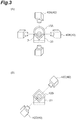
- Region (A) of FIG. 3 illustrates an example of an arrangement of the imaging unit 40 with respect to the observation container 10A having a cylindrical shape.
- Region (A) of FIG. 3 illustrates the observation container 10A on the support stand 20, and the support stand 20 is arranged at a position out of the field of view of the imaging unit 40. This point is the same also for region (B) of FIG. 3 .
- an arrangement of the imaging unit 40 is not particularly limited, and the imaging unit 40 may be arranged at a position to suitably capture an image of the object 2. Therefore, as illustrated in region (A) of FIG. 3 , an arrangement of the imaging unit 40 with respect to the observation container 10A and the object 2 can be appropriately changed.
- the imaging unit 40 may be configured to be arranged at a position where an optical axis of light which passes through a wall surface of the observation container 10A to be incident into the imaging unit 40 is orthogonal to the wall surface of the container. With such a configuration, the imaging unit 40 can be prevented from receiving reflected light, refracted light, or the like from the wall surface of the container.
- a configuration where a plurality of the imaging units 40 are provided may be adopted.
- the plurality of imaging units 40 may be arranged in positions where optical axes are orthogonal to each other around the object 2.
- an image of the shape of the fine particle that is the object 2 can be suitably captured by the imaging units 40A and 40B.
- the imaging units 40A and 40B may be configured to capture an image of the same imaging target at the same time.
- one imaging target (object 2) in the observation container 10A can be identified from different directions.
- the object 2 can be considered to rotate as the liquid sample moves. Therefore, the imaging units 40A and 40B are configured to capture an image of the observation container 10A in a specific position, and thus more detailed information on the object 2 can be acquired.
- the expression "that an image of the same imaging target is captured at the same time” refers to that as seen along a longitudinal direction of the observation container 10, the positions of the fields of view of the imaging units 40A and 40B are the same and an image of the object 2 staying at a certain point in the observation container 10 is captured at the same time.
- Region (B) of FIG. 3 illustrates an example of an arrangement of the imaging unit 40 when the observation container 10B has a square tube shape.
- the imaging unit 40 may be configured to be arranged at a position where an optical axis of light which passes through a wall surface of the observation container 10B to be incident into the imaging unit 40 is orthogonal to the wall surface of the container. With such a configuration, the imaging unit 40 can be prevented from receiving reflected light, refracted light, or the like from the wall surface of the container.
- the imaging unit 40 may be arranged to face the wall surface that is flat and included in the observation container 10B having a square tube shape.
- imaging units 40C and 40D may be arranged to face each other while interposing the observation container 10B having a square tube shape therebetween.
- the imaging units 40C and 40D are in such an arrangement and are configured to capture an image of the same imaging target at the same time, the imaging units 40C and 40D can capture the entire image of the object in the observation container 10B.
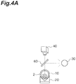
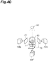
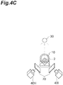
- FIGS. 4A , 4B , and 4C illustrates examples of an arrangement of the light source unit 30 and the imaging unit 40.
- FIG. 1 describes a case where the light source unit 30 and the imaging unit 40 face each other while interposing the observation container 10 therebetween, and a positional relationship between the light source unit 30 and the imaging unit 40 can be appropriately changed.
- an example illustrated in FIG. 4A has an configuration where a half-silvered mirror 60 is provided, light from the light source unit 30 is reflected by the half-silvered mirror 60 to irradiate the object 2, and the light from the object 2 transmits through the half-silvered mirror 60 to be incident into the imaging unit 40.
- a configuration using an optical element or the like that changes the path of light may be adopted.
- three imaging units 40 (40E to 40G) are provided for one light source unit 30.
- an imaging unit 40F is arranged to face the light source unit 30 with the observation container 10 (object 2) interposed therebetween.
- Imaging units 40E and 40G are arranged at positions where optical axes of light incident into the imaging units are at 90° with respect to an optical axis of light from the light source unit 30 toward the object 2.
- a filter 70 that restricts light of a specific wavelength toward the imaging unit 40 a filter that blocks light of the specific wavelength including the excitation light may be provided in a front stage of each of the imaging units 40.
- a filter that blocks light of a specific wavelength may be provided as the filter 70.
- two imaging units 40 (40H and 401) are provided for one light source unit 30.
- Two imaging units 40H and 401 are arranged at positions where optical axes of light incident into the imaging units are at 60° with respect to an optical axis of light from the light source unit 30 toward the object 2. For this reason, the imaging units 40H and 401 can capture an image of reflected light from the object 2 or an image of fluorescent light when the object 2 emits the fluorescent light.
- the filter 70 that restricts the wavelength of light incident into each of the imaging units 40 is arranged in the front stage of each of the imaging units 40.
- the numbers of the light source units 30 and the imaging units 40 may differ from each other.
- the transmitted wavelengths of the filters 70 provided in the front stages of the plurality of imaging units 40 may differ from each other.
- the observation container 10 is accommodated in the groove F of the support stand 20 and supported by the support stand 20, and a pressing jig can be used as means that restricts a movement of the observation container 10 on the support stand 20.
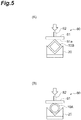
- FIG. 5 illustrates an example of a pressing jig 80.
- the pressing jig 80 includes a pressing portion 81 having a pressing surface 81a to be pressed against the observation container 10 and a holding portion 82 that a user of the pressing jig 80 holds when handling the pressing portion 81.
- Region (A) of FIG. 5 illustrates a state where the observation container 10B having a square tube shape is accommodated in the groove F of the support stand 20 and the observation container 10B is supported from above by the pressing jig 80.
- region (B) of FIG. 5 illustrates a state where the observation container 10A having a cylindrical shape is accommodated in the groove F of the support stand 20 and the observation container 10B is supported from above by the pressing jig 80.
- the pressing portion 81 is connected to the holding portion 82 via a spring 83.
- the pressing portion 81 of the pressing jig 80A is connected to the holding portion 82 via the spring 83.
- region (B) of FIG. 6 in a state where the observation container 10 is pressed (supported), the pressing portion 81 of the pressing jig 80A is pressed and supported from above via the holding portion 82 and the spring 83.
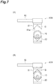
- a groove G is formed in the pressing surface 81a of the pressing portion 81.
- a transition is made from a state in which the observation container 10 is not pressed and which is illustrated in region (A) of FIG. 7 to a state in which the observation container 10 is pressed (supported) and which is illustrated in region (B) of FIG. 7 , since the observation container 10 is accommodated in the groove G of the pressing surface 10a, a movement of the observation container 10 can be suitably restricted.
- the pressing jig 80B is used in such a manner that the longitudinal direction of the observation container 10 (extending direction of the groove F of the support stand 20) coincides with an extending direction of the groove G in the pressing surface 81a of the pressing jig 80B.
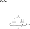
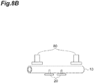
- FIGS. 8A , 8B , and 8C are views illustrating examples of the positional relationship between the support stand 20 and the pressing jig 80.
- FIG. 8A illustrates a state where the support stand 20 and the pressing jig 80 are arranged to face each other with the observation container 10 interposed therebetween.
- FIG. 8B illustrates a state where two support stands 20 support a central side in the longitudinal direction of the observation container 10, whereas two pressing jigs 80 support end portion sides in the longitudinal direction of the observation container 10.
- FIG. 8C illustrates a state where two support stands 20 support end portion sides in the longitudinal direction of the observation container 10, whereas one pressing jig 80 supports the vicinity of the center in the longitudinal direction of the observation container 10.
- the numbers of the support stands 20 and the pressing jigs 80 and the positional relationship therebetween can be appropriately changed.
- both of the support stand 20 and the pressing jig 80 may be configured to be provided at positions out of the field of view of the imaging unit 40. Therefore, as illustrated in FIG. 8C , when the pressing jig 80 is arranged in the vicinity of the center of the observation container 10, the imaging unit 40 may be arranged between the support stand 20 and the pressing jig 80 along the longitudinal direction of the observation container 10.
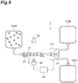
- FIG. 9 An application example of the fine particle measurement device described above will be described with reference to FIG. 9 .
- the culture bag is connected to the observation container 10 placed in the fine particle measurement device 1.
- the point of coincidence is that the culture bag 100A is connected to one (upstream side) end portion, and the point of difference is that two culture bags 100B and 100C are connected to the other (downstream side) end portion and a branch portion 110 connected to a flow path to the culture bag 100B and a flow path to the culture bag 100C is connected to a rear stage of the observation container 10.
- the imaging unit 40 captures images of the objects 2 and the analyzer 50 performs an analysis on the objects 2. Then, a valve 111 provided in the branch portion 110 is controlled according to the result to cause the objects 2 to move to either of the culture bag 100B and the culture bag 100C.
- a configuration where the objects 2 are sorted by using analysis results obtained by the fine particle measurement device 1 may be adopted.
- the objects 2 having diameters exceeding a predetermined diameter may be moved to the culture bag 100B, and the other objects 2 may be moved to the culture bag 100C.
- the way the objects 2 are sorted by using the analysis results can be appropriately changed.
- a configuration where only the objects 2 satisfying a specific condition are recovered and the other objects 2 are discarded may be adopted.
- the configuration of the branch portion 110 that sorts the fine particles can be appropriately changed.
- FIGS. 1 and 2 and the like describe a case where the observation container 10 has a cylindrical shape and the culture bags 100A and 100B and the like are connected to both ends thereof; however, the observation container may be a recessed container and may have a structure where the liquid sample is contained therein. In addition, the observation container may have a structure where a plurality of recessed portions are provided to individually accommodate the objects 2.
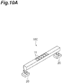
- FIG. 10A is a perspective view illustrating an observation container 10C according to the modification example together with the support stand.
- the observation container 10C has a structure where a plurality of recessed portions 11 are independent of each other as described above.
- observation container 10C is an elongated columnar member and the plurality of recessed portions 11 are formed in the vicinity of the center thereof.
- a region of the observation container 10C (for example, an end portion of the observation container 10C), in which the recessed portion 11 is not formed, can be supported by the support stand 20.
- FIG. 10B is a conceptual view illustrating one example of the cross section of the observation container 10C and an arrangement of the imaging unit, and illustrates an example where the recessed portion 11 is formed of bottom walls 12A and 12B made of two plate-shaped members.
- the angle formed by the two bottom walls 12A and 12B is not particularly limited, but may be approximately 90° or in a range of 90° ⁇ 30°.
- two imaging units 40 can use the two bottom walls 12A and 12B to suitably obtain an image used to three-dimensionally identify the shape of the fine particle that is the object 2.
- the imaging units can suitably capture an image of the shape of the fine particle that is the object 2.
- the recessed portions 11 different from each other may be configured to accommodate the object 2 one by one.
- a plurality of the objects 2 can be prevented from being falsely observed and a movement of each of the objects 2 is also restricted, and thus an analysis on the object 2 can be suitably performed.
- the observation container 10C may be configured such that one recessed portion 11 extending in the longitudinal direction is provided.
- the shape of the bottom wall of the observation container 10 can be appropriately changed.
- the observation container 10C on the support stand 20 or the imaging unit 40 may be configured to be moved along an extending direction (longitudinal direction) of the observation container 10C, so that the object (recessed portion in which the object 2 is accommodated) in the field of view of the imaging unit 40 is changed.
- the fine particle measurement device 1 may be configured such that a movement mechanism which moves the observation container 10C or a movement mechanism which moves the imaging unit 40 is provided.
- the movement mechanism that moves the observation container 10C the observation container 10C itself may be moved or the support stand 20 may be moved to be able to move the support stand 20 and the observation container 10C at the same time.
- the fine particle measurement device 1 may be configured such that a movement mechanism which moves the observation container 10D or a movement mechanism which moves the imaging unit 40 is provided.
- the fine particle measurement device 1 may be configured to include a movement mechanism.
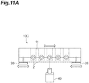
- one observation container 10 is supported by two support stands 20
- the number or shape of the support stands 20 that support the observation container 10 can be appropriately changed.
- a configuration where one observation container 10 is supported by three support stands 20 may be adopted.
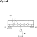
- a configuration where one observation container 10 (here, representing the observation container 10D) is supported by one support stand 20 may be adopted.
- the thickness (length along the extending direction of the observation container 10D) of the container support portion 22 of the support stand 20A is larger than that of the support stand 20 illustrated in FIGS. 1 and 2 and the like.
- the observation container 10D can be stably supported by the groove F of the container support portion 22. Therefore, even if the number of the support stands 20 is reduced, the observation container 10 (10D) can be suitably supported.
- the imaging unit 40 can be arranged at a position where the support stand 20 is out of the field of view (for example, on an end portion side of the observation container). With such a configuration, the object 2 can be suitably observed.
- FIGS. 13A , 13B , and 14 illustrate modification examples of the fine particle measurement device.
- FIG. 13A is a perspective view illustrating a state where a lid portion 92 of a fine particle measurement device 1A is closed
- FIG. 13B is a perspective view illustrating a state where the lid portion 92 of the fine particle measurement device 1A is opened.
- the support stand 20, the light source unit 30, and the imaging unit 40 are installed in an outer packaging 90 for transport.
- the outer packaging 90 includes a main body portion 91 and the lid portion 92, and as transporting means for transporting the outer packaging 90, a handle 93 is attached to the main body portion 91.
- the observation container 10, the support stand 20, the light source unit 30, and the imaging unit 40 are installed in the outer packaging 90.
- the lid portion 92 is closed and the handle 93 can be used to carry the fine particle measurement device 1.
- the lid portion 92 is opened, the observation container 10 is set on the support stand 20 in the outer packaging 90, and a measurement is performed.
- the fine particle measurement device 1A can be transported to any place to be used, so that the versatility of the fine particle measurement device 1A is improved.
- a caster 94 may be configured to be provided in the main body portion 91, so that the fine particle measurement device 1A can be transported.
- the position where the caster 94 is provided can be appropriately changed.
- the observation container 10 is accommodated in the groove F of the support stand 20, and thus the observation container 10 can be supported such that the extending direction of the groove F coincides with the longitudinal direction.
- the imaging unit 40 is configured to capture an image of the fine particle at the position where the support stand 20 is out of the field of view, the image of the fine particle can be captured in a state where the observation container 10 is properly supported, and thus the image of the shape of the fine particle can be more accurately captured.
- the groove F of the support stand 20 has a V shape, regardless of the shape of a bottom portion of the observation container 10, the observation container 10 can be accommodated in and suitably supported by the groove F.
- the pressing jig 80 that is configured to press the observation container 10 is further provided, a movement of the observation container 10 on the support stand 20 can be restricted, so that an image of the fine particle can be more suitably captured.
- the movement mechanism that is configured to move the support stand 20, the observation container 10, or the imaging unit 40 since the movement mechanism that is configured to move the support stand 20, the observation container 10, or the imaging unit 40 is provided, the field of view of the imaging unit 40 can be easily changed, so that an image of the fine particle in the observation container 10 can be more simply captured.
- the light source unit 30 is provided, for example, an image of fluorescent light that the fine particle emits in response to light from the light source unit 30 can be captured, and thus when the imaging unit 40 captures the image, a wider range of information on the fine particle can be obtained.
- the light source unit 30 is not provided, for example, the fine particle can be observed; however, since the light source unit 30 is provided, an observation using light of a specific wavelength can be suitably performed.
- the fine particle measurement device since the outer packaging 90 in which the support stand 20, the light source unit 30, and the imaging unit 40 are installed is provided, the fine particle measurement device can be easily moved, so that the versatility is improved.
- the fine particle measurement device can be more simply transported.
- the fine particle measurement device 1 is not limited to the above embodiments.
- the configuration where the fine particle measurement device 1 includes the observation container 10, the support stand 20, the light source unit 30, the imaging unit 40, and the analyzer 50 as in the above embodiments, for example, a configuration where the light source unit is not provided may be adopted.
- the number of the light source units or the imaging units may be 3 or more.
- the observation container 10 may not be included in the fine particle measurement device.
- the shape of the observation container 10 can be appropriately changed.
- the object 2 may be able to stay at least in the observation container 10. Therefore, as with the observation containers 10A and 10B, a configuration where the liquid sample containing the object 2 is accommodated through an opening connected to the outside may be adopted, or as with the observation containers 10C and 10D, a configuration where one or a plurality of the recessed portions 11 are provided may be adopted.
- 1, 1A fine particle measurement device
- 10 observation container
- 11 recessed portion
- 20 support stand
- 30 light source unit
- 40 imaging unit
- 50 analyzer
- 80 pressing jig
- 90 outer packaging.
Landscapes
- Chemical & Material Sciences (AREA)
- Health & Medical Sciences (AREA)
- Life Sciences & Earth Sciences (AREA)
- General Health & Medical Sciences (AREA)
- Biochemistry (AREA)
- Analytical Chemistry (AREA)
- Zoology (AREA)
- Engineering & Computer Science (AREA)
- Bioinformatics & Cheminformatics (AREA)
- Organic Chemistry (AREA)
- Wood Science & Technology (AREA)
- Physics & Mathematics (AREA)
- General Physics & Mathematics (AREA)
- Immunology (AREA)
- Pathology (AREA)
- Dispersion Chemistry (AREA)
- Sustainable Development (AREA)
- General Engineering & Computer Science (AREA)
- Microbiology (AREA)
- Genetics & Genomics (AREA)
- Biotechnology (AREA)
- Biomedical Technology (AREA)
- Investigating Or Analysing Materials By Optical Means (AREA)
- Microscoopes, Condenser (AREA)
Applications Claiming Priority (2)
| Application Number | Priority Date | Filing Date | Title |
|---|---|---|---|
| JP2018052953 | 2018-03-20 | ||
| PCT/JP2019/010936 WO2019181803A1 (ja) | 2018-03-20 | 2019-03-15 | 微小粒子計測装置 |
Publications (3)
| Publication Number | Publication Date |
|---|---|
| EP3770580A1 true EP3770580A1 (de) | 2021-01-27 |
| EP3770580A4 EP3770580A4 (de) | 2021-05-19 |
| EP3770580B1 EP3770580B1 (de) | 2025-08-20 |
Family
ID=67987316
Family Applications (1)
| Application Number | Title | Priority Date | Filing Date |
|---|---|---|---|
| EP19772371.1A Active EP3770580B1 (de) | 2018-03-20 | 2019-03-15 | Feinpartikelmessvorrichtung |
Country Status (5)
| Country | Link |
|---|---|
| US (1) | US11768146B2 (de) |
| EP (1) | EP3770580B1 (de) |
| JP (1) | JP7272348B2 (de) |
| CN (1) | CN111868504A (de) |
| WO (1) | WO2019181803A1 (de) |
Families Citing this family (3)
| Publication number | Priority date | Publication date | Assignee | Title |
|---|---|---|---|---|
| DE102023101477A1 (de) * | 2023-01-20 | 2024-07-25 | Testo bioAnalytics GmbH | Verfahren und Aufnahmeraum zur optischen Aufzeichnung von Mikropartikeln und Verwendung einer Bewegungskomponente zur Entfernung eines Abdeckelements vor einer Aufzeichnung |
| CN116183465B (zh) * | 2023-04-23 | 2023-10-27 | 太原理工大学 | 矿井透水相似模拟实验装置及方法 |
| KR102629589B1 (ko) * | 2023-10-23 | 2024-01-29 | (주)엘로이랩 | 유동형 대상물에 대한 기계학습이 적용된 자동화된 품질 검사 및 이물 추출 시스템 및 기계학습을 이용한 자동화된 품질 검사 및 이물 추출 방법 |
Family Cites Families (32)
| Publication number | Priority date | Publication date | Assignee | Title |
|---|---|---|---|---|
| US5074662A (en) | 1990-02-27 | 1991-12-24 | Hoechst Celanese Corporation | Sample holder for spectroscopic studies of optical film |
| JP3136574B2 (ja) * | 1992-02-29 | 2001-02-19 | 株式会社島津製作所 | 微量液体試料の分光特性測定装置 |
| JPH0735679A (ja) * | 1993-07-23 | 1995-02-07 | Rion Co Ltd | 微粒子計 |
| JPH1073528A (ja) * | 1996-08-30 | 1998-03-17 | Toa Medical Electronics Co Ltd | 撮像機能付きフローサイトメータ |
| US5998224A (en) | 1997-05-16 | 1999-12-07 | Abbott Laboratories | Magnetically assisted binding assays utilizing a magnetically responsive reagent |
| US6369893B1 (en) * | 1998-05-19 | 2002-04-09 | Cepheid | Multi-channel optical detection system |
| JPH11295208A (ja) * | 1998-04-13 | 1999-10-29 | Sysmex Corp | 粒子撮像装置 |
| US6184990B1 (en) * | 1999-12-22 | 2001-02-06 | Beckman Coulter, Inc. | Miniature multiple wavelength excitation and emission optical system and method for laser-induced fluorescence detectors in capillary electrophoresis |
| JP2001221736A (ja) | 2000-02-10 | 2001-08-17 | Hamamatsu Photonics Kk | 発光、吸光又は蛍光測定装置 |
| US6522775B2 (en) | 2001-03-28 | 2003-02-18 | Alan C. Nelson | Apparatus and method for imaging small objects in a flow stream using optical tomography |
| US6603535B1 (en) * | 2002-08-30 | 2003-08-05 | The United States Of America As Represented By The Administrator Of The National Aeronautics And Space Administration | Stereo imaging velocimetry system and method |
| JP4234579B2 (ja) * | 2003-12-19 | 2009-03-04 | 富士通株式会社 | 微小粒子の観察方法及び装置 |
| US8211386B2 (en) * | 2004-06-08 | 2012-07-03 | Biokit, S.A. | Tapered cuvette and method of collecting magnetic particles |
| US7307721B2 (en) | 2005-04-13 | 2007-12-11 | Brightwell Technologies | Particle imaging system with a varying flow rate |
| US9810707B2 (en) | 2006-05-17 | 2017-11-07 | Luminex Corporation | Chip-based flow cytometer type systems for analyzing fluorescently tagged particles |
| DE102007048409A1 (de) | 2007-10-09 | 2009-04-16 | Carl Zeiss Microimaging Gmbh | Verfahren zum Positionieren von biologischen Proben in einer mikroskopischen Anordnung |
| JP5246571B2 (ja) | 2008-02-06 | 2013-07-24 | 日本パルスモーター株式会社 | シリンダユニット |
| JP4805416B1 (ja) * | 2010-03-31 | 2011-11-02 | 古河電気工業株式会社 | 光情報解析装置及び光情報解析方法 |
| EP2450690A1 (de) * | 2010-11-04 | 2012-05-09 | Qiagen GmbH | Gefäss für exakte optische Messungen |
| CN107402178B (zh) | 2011-04-15 | 2020-05-05 | 罗氏血液诊断股份有限公司 | 测量细胞体积和成份 |
| JP2018052953A (ja) | 2011-11-28 | 2018-04-05 | ヤンセン ファッシンズ アンド プリベンション ベーフェーJanssen Vaccines & Prevention B.V. | インフルエンザウイルスワクチンおよびその使用 |
| JP5928888B2 (ja) | 2012-06-11 | 2016-06-01 | 横河電機株式会社 | 細胞観察装置 |
| DE102012108158B4 (de) | 2012-09-03 | 2016-03-17 | Johann Wolfgang Goethe-Universität | Kapillarzelle, Anordnung und Verfahren zur Aufnahme, zur Positionierung und zur Untersuchung einer mikroskopischen Probe |
| CN203487155U (zh) * | 2013-06-21 | 2014-03-19 | 汉斯·葛根森 | 细胞分离和收集器 |
| DE202013012338U1 (de) * | 2013-07-10 | 2016-04-29 | Carl Zeiss Microscopy Gmbh | Anordnung zur Lichtblattmikroskopie |
| DE102013110093B3 (de) | 2013-09-13 | 2015-01-22 | Johann Wolfgang Goethe-Universität | Küvette für eine inverse Fluoreszenz-Untersuchung |
| CN110243752B (zh) * | 2014-03-07 | 2022-12-02 | 古河电气工业株式会社 | 筛选装置和筛选方法 |
| JP6104475B2 (ja) * | 2014-08-28 | 2017-04-05 | シスメックス株式会社 | 粒子撮像装置および粒子撮像方法 |
| JP6577793B2 (ja) | 2015-08-28 | 2019-09-18 | 株式会社Screenホールディングス | 光規制器具および撮像方法 |
| JP2017215216A (ja) * | 2016-05-31 | 2017-12-07 | シスメックス株式会社 | 分析方法および分析装置 |
| JP2017219479A (ja) * | 2016-06-09 | 2017-12-14 | 住友電気工業株式会社 | 微小粒子計測装置及び分析方法 |
| EP3633350A4 (de) | 2017-05-29 | 2020-06-03 | Sumitomo Electric Industries, Ltd. | Beobachtungsbehälter und mikroteilchenmessvorrichtung |
-
2019
- 2019-03-15 CN CN201980020011.7A patent/CN111868504A/zh active Pending
- 2019-03-15 JP JP2020507763A patent/JP7272348B2/ja active Active
- 2019-03-15 EP EP19772371.1A patent/EP3770580B1/de active Active
- 2019-03-15 WO PCT/JP2019/010936 patent/WO2019181803A1/ja not_active Ceased
-
2020
- 2020-09-17 US US17/023,566 patent/US11768146B2/en active Active
Also Published As
| Publication number | Publication date |
|---|---|
| US11768146B2 (en) | 2023-09-26 |
| WO2019181803A1 (ja) | 2019-09-26 |
| JPWO2019181803A1 (ja) | 2021-04-08 |
| JP7272348B2 (ja) | 2023-05-12 |
| EP3770580A4 (de) | 2021-05-19 |
| EP3770580B1 (de) | 2025-08-20 |
| US20210003494A1 (en) | 2021-01-07 |
| CN111868504A (zh) | 2020-10-30 |
Similar Documents
| Publication | Publication Date | Title |
|---|---|---|
| US11768146B2 (en) | Fine particle measurement device | |
| CN107003230B (zh) | 用于光学检查小体积的液体样品的设备和其比色杯 | |
| US6249341B1 (en) | Imaging and analyzing parameters of small moving objects such as cells | |
| EP3353529B1 (de) | Küvettenträger | |
| CA2533140A1 (en) | Wide field method for detecting pathogenic microorganisms | |
| EP2905605B1 (de) | Vorrichtung zur Messung von Lichtstreuung | |
| JP2018522209A (ja) | 光応答の色スペクトル分解を用いた自動インビトロ検体検出のための装置及び方法 | |
| US20160252453A1 (en) | Array based sample characterization | |
| CN110837182A (zh) | 用于样品完整性验证的系统、装置和方法 | |
| CN111337392A (zh) | 一种悬浮颗粒偏振荧光同步测量装置 | |
| JP2017219479A (ja) | 微小粒子計測装置及び分析方法 | |
| WO2017195772A1 (ja) | 腫瘍細胞検出方法及び腫瘍細胞検出装置 | |
| JP2021143988A (ja) | 粒子解析システムおよび粒子解析方法 | |
| US9417176B2 (en) | Method and apparatus for detecting and registering properties of samples | |
| US11333596B2 (en) | Observation container and microparticle measurement device | |
| EP1353166A3 (de) | Diffraktionssystem zur Überwachung biologischer Kristalle | |
| Huffman et al. | A wavelength-dispersive instrument for characterizing fluorescence and scattering spectra of individual aerosol particles on a substrate | |
| WO2012045846A1 (en) | Apparatus and method for supporting a liquid sample for measuring scattering of electromagnetic radiation | |
| US20120057019A1 (en) | Dynamic In-Situ Feature Imager Apparatus and Method | |
| EP3290984A1 (de) | Mikroskopvorrichtung | |
| WO2006083316A2 (en) | Multipoint method for identifying hazardous agents | |
| ES2986358T3 (es) | Sistema de obtención de imágenes para contar y dimensionar partículas en recipientes llenos de fluido | |
| JP2004101323A (ja) | X・y精子の選別方法及び装置 | |
| WO2005095923A1 (en) | Improved detection device | |
| US20210331155A1 (en) | Biological agent specimen collection and growth system |
Legal Events
| Date | Code | Title | Description |
|---|---|---|---|
| STAA | Information on the status of an ep patent application or granted ep patent |
Free format text: STATUS: THE INTERNATIONAL PUBLICATION HAS BEEN MADE |
|
| PUAI | Public reference made under article 153(3) epc to a published international application that has entered the european phase |
Free format text: ORIGINAL CODE: 0009012 |
|
| STAA | Information on the status of an ep patent application or granted ep patent |
Free format text: STATUS: REQUEST FOR EXAMINATION WAS MADE |
|
| 17P | Request for examination filed |
Effective date: 20200921 |
|
| AK | Designated contracting states |
Kind code of ref document: A1 Designated state(s): AL AT BE BG CH CY CZ DE DK EE ES FI FR GB GR HR HU IE IS IT LI LT LU LV MC MK MT NL NO PL PT RO RS SE SI SK SM TR |
|
| AX | Request for extension of the european patent |
Extension state: BA ME |
|
| A4 | Supplementary search report drawn up and despatched |
Effective date: 20210416 |
|
| RIC1 | Information provided on ipc code assigned before grant |
Ipc: G01N 15/14 20060101AFI20210412BHEP Ipc: G01N 21/01 20060101ALI20210412BHEP |
|
| DAV | Request for validation of the european patent (deleted) | ||
| DAX | Request for extension of the european patent (deleted) | ||
| STAA | Information on the status of an ep patent application or granted ep patent |
Free format text: STATUS: EXAMINATION IS IN PROGRESS |
|
| 17Q | First examination report despatched |
Effective date: 20231013 |
|
| REG | Reference to a national code |
Ref legal event code: R079 Ipc: G01N0015143400 Ref country code: DE Ref document number: 602019074425 Country of ref document: DE Free format text: PREVIOUS MAIN CLASS: G01N0015140000 |
|
| GRAP | Despatch of communication of intention to grant a patent |
Free format text: ORIGINAL CODE: EPIDOSNIGR1 |
|
| STAA | Information on the status of an ep patent application or granted ep patent |
Free format text: STATUS: GRANT OF PATENT IS INTENDED |
|
| RIC1 | Information provided on ipc code assigned before grant |
Ipc: G01N 15/10 20060101ALI20250324BHEP Ipc: G01N 21/03 20060101ALI20250324BHEP Ipc: C12M 1/00 20060101ALI20250324BHEP Ipc: C12M 1/34 20060101ALI20250324BHEP Ipc: G01N 15/14 20060101ALI20250324BHEP Ipc: G01N 15/1434 20240101AFI20250324BHEP |
|
| INTG | Intention to grant announced |
Effective date: 20250403 |
|
| GRAS | Grant fee paid |
Free format text: ORIGINAL CODE: EPIDOSNIGR3 |
|
| GRAA | (expected) grant |
Free format text: ORIGINAL CODE: 0009210 |
|
| STAA | Information on the status of an ep patent application or granted ep patent |
Free format text: STATUS: THE PATENT HAS BEEN GRANTED |
|
| P01 | Opt-out of the competence of the unified patent court (upc) registered |
Free format text: CASE NUMBER: APP_31496/2025 Effective date: 20250701 |
|
| AK | Designated contracting states |
Kind code of ref document: B1 Designated state(s): AL AT BE BG CH CY CZ DE DK EE ES FI FR GB GR HR HU IE IS IT LI LT LU LV MC MK MT NL NO PL PT RO RS SE SI SK SM TR |
|
| REG | Reference to a national code |
Ref country code: GB Ref legal event code: FG4D |
|
| REG | Reference to a national code |
Ref country code: CH Ref legal event code: EP |
|
| REG | Reference to a national code |
Ref country code: IE Ref legal event code: FG4D |
|
| REG | Reference to a national code |
Ref country code: DE Ref legal event code: R096 Ref document number: 602019074425 Country of ref document: DE |