EP3770562B1 - Vorrichtung zur detektion des füllstands eines brunnens/tanks und elektrische tauchpumpe mit der vorrichtung - Google Patents
Vorrichtung zur detektion des füllstands eines brunnens/tanks und elektrische tauchpumpe mit der vorrichtung Download PDFInfo
- Publication number
- EP3770562B1 EP3770562B1 EP20184310.9A EP20184310A EP3770562B1 EP 3770562 B1 EP3770562 B1 EP 3770562B1 EP 20184310 A EP20184310 A EP 20184310A EP 3770562 B1 EP3770562 B1 EP 3770562B1
- Authority
- EP
- European Patent Office
- Prior art keywords
- well
- level
- detecting
- tank
- electric immersion
- Prior art date
- Legal status (The legal status is an assumption and is not a legal conclusion. Google has not performed a legal analysis and makes no representation as to the accuracy of the status listed.)
- Active
Links
Images


Classifications
-
- G—PHYSICS
- G01—MEASURING; TESTING
- G01F—MEASURING VOLUME, VOLUME FLOW, MASS FLOW OR LIQUID LEVEL; METERING BY VOLUME
- G01F23/00—Indicating or measuring liquid level or level of fluent solid material, e.g. indicating in terms of volume or indicating by means of an alarm
- G01F23/14—Indicating or measuring liquid level or level of fluent solid material, e.g. indicating in terms of volume or indicating by means of an alarm by measurement of pressure
-
- F—MECHANICAL ENGINEERING; LIGHTING; HEATING; WEAPONS; BLASTING
- F04—POSITIVE - DISPLACEMENT MACHINES FOR LIQUIDS; PUMPS FOR LIQUIDS OR ELASTIC FLUIDS
- F04D—NON-POSITIVE-DISPLACEMENT PUMPS
- F04D13/00—Pumping installations or systems
- F04D13/02—Units comprising pumps and their driving means
- F04D13/06—Units comprising pumps and their driving means the pump being electrically driven
- F04D13/08—Units comprising pumps and their driving means the pump being electrically driven for submerged use
-
- F—MECHANICAL ENGINEERING; LIGHTING; HEATING; WEAPONS; BLASTING
- F04—POSITIVE - DISPLACEMENT MACHINES FOR LIQUIDS; PUMPS FOR LIQUIDS OR ELASTIC FLUIDS
- F04D—NON-POSITIVE-DISPLACEMENT PUMPS
- F04D13/00—Pumping installations or systems
- F04D13/02—Units comprising pumps and their driving means
- F04D13/06—Units comprising pumps and their driving means the pump being electrically driven
- F04D13/08—Units comprising pumps and their driving means the pump being electrically driven for submerged use
- F04D13/086—Units comprising pumps and their driving means the pump being electrically driven for submerged use the pump and drive motor are both submerged
-
- F—MECHANICAL ENGINEERING; LIGHTING; HEATING; WEAPONS; BLASTING
- F04—POSITIVE - DISPLACEMENT MACHINES FOR LIQUIDS; PUMPS FOR LIQUIDS OR ELASTIC FLUIDS
- F04D—NON-POSITIVE-DISPLACEMENT PUMPS
- F04D15/00—Control, e.g. regulation, of pumps, pumping installations or systems
-
- F—MECHANICAL ENGINEERING; LIGHTING; HEATING; WEAPONS; BLASTING
- F04—POSITIVE - DISPLACEMENT MACHINES FOR LIQUIDS; PUMPS FOR LIQUIDS OR ELASTIC FLUIDS
- F04D—NON-POSITIVE-DISPLACEMENT PUMPS
- F04D15/00—Control, e.g. regulation, of pumps, pumping installations or systems
- F04D15/02—Stopping of pumps, or operating valves, on occurrence of unwanted conditions
- F04D15/0209—Stopping of pumps, or operating valves, on occurrence of unwanted conditions responsive to a condition of the working fluid
- F04D15/0218—Stopping of pumps, or operating valves, on occurrence of unwanted conditions responsive to a condition of the working fluid the condition being a liquid level or a lack of liquid supply
-
- F—MECHANICAL ENGINEERING; LIGHTING; HEATING; WEAPONS; BLASTING
- F04—POSITIVE - DISPLACEMENT MACHINES FOR LIQUIDS; PUMPS FOR LIQUIDS OR ELASTIC FLUIDS
- F04D—NON-POSITIVE-DISPLACEMENT PUMPS
- F04D29/00—Details, component parts, or accessories
- F04D29/18—Rotors
- F04D29/20—Mounting rotors on shafts
-
- G—PHYSICS
- G01—MEASURING; TESTING
- G01F—MEASURING VOLUME, VOLUME FLOW, MASS FLOW OR LIQUID LEVEL; METERING BY VOLUME
- G01F23/00—Indicating or measuring liquid level or level of fluent solid material, e.g. indicating in terms of volume or indicating by means of an alarm
- G01F23/14—Indicating or measuring liquid level or level of fluent solid material, e.g. indicating in terms of volume or indicating by means of an alarm by measurement of pressure
- G01F23/18—Indicating, recording or alarm devices actuated electrically
-
- G—PHYSICS
- G08—SIGNALLING
- G08C—TRANSMISSION SYSTEMS FOR MEASURED VALUES, CONTROL OR SIMILAR SIGNALS
- G08C17/00—Arrangements for transmitting signals characterised by the use of a wireless electrical link
- G08C17/02—Arrangements for transmitting signals characterised by the use of a wireless electrical link using a radio link
-
- H—ELECTRICITY
- H02—GENERATION; CONVERSION OR DISTRIBUTION OF ELECTRIC POWER
- H02K—DYNAMO-ELECTRIC MACHINES
- H02K5/00—Casings; Enclosures; Supports
- H02K5/04—Casings or enclosures characterised by the shape, form or construction thereof
- H02K5/12—Casings or enclosures characterised by the shape, form or construction thereof specially adapted for operating in liquid or gas
- H02K5/132—Submersible electric motors
Definitions
- the present invention relates to a device for detecting the level of a well/tank.
- the invention is applied in particular for the detection of the level of a well/tank in which an electric immersion pump is used.
- the present invention also relates to an electric pump provided with such a device.
- Electric immersion pumps are electric pumps that are used inside wells and/or tanks to draw the liquid (normally water) contained therein.
- free surface is understood to refer to the separation surface between the liquid phase (liquid contained in the well/tank) and the gaseous phase (air).
- level probes including immersion probes, are widely used.
- These immersion probes are immersed in the well/tank, usually to the bottom, and measure the filling level or height of the well/tank according to the principle by which a liquid generates, with its relative density and the force of gravity, a weight force that increases proportionally with the filling level.
- These probes comprise a measurement end, which contains for example a silicon strain gauge and the electronic devices for evaluating the variations of the former, from which one or more metallic cables with capillaries extend in order to compensate for atmospheric pressure.
- the measurement of the level is provided by determining the difference between the ambient pressure, measured by a sensor outside the tank, and the pressure measured by the probe.
- level probes of the float type are used, for example.
- float probes comprise, inside the float, a magnet which moves as a function of the movement of the level of the well/tank and interacts with one or more electrical contacts of the reed type, modifying their electrical condition.
- these probes have at least one cable that must be connected to a dedicated user interface that is external to the well/tank.
- US2013133881A1 relates to a a progressive-cavity pump comprising a motor speed control, a pump pressure sensor located at the pump depth; a casing pressure sensor located at the casing head of the well and a programmable computer connected to the first and second pressure sensors and the motor speed control.
- the aim of the present invention is to provide a device for detecting the level of a well/tank and an electric immersion pump with such a device which are capable of improving the background art in one or more of the aspects indicated above.
- an object of the invention is to provide a device for detecting the level of a well/tank that can be installed easily by the user and at any time.
- Another object of the invention is to provide a device for detecting the level of a well/tank that is at least partially integrated in an electric pump used in said well/tank.
- Another object of the invention is to provide a device for detecting the level of a well/tank without the need to provide a dedicated access to the well/tank for its power supply and its operation but utilizes the same access to the well/tank that the electric pump used.
- Another object of the invention is to provide an electric pump which comprises a device for detecting the level of a well/tank capable of achieving the aim and objects listed above.
- Another object of the present invention is to overcome the drawbacks of the background art in a manner that is alternative to any existing solutions.
- Another object of the invention is to provide a device for detecting the level of a well/tank and an electric immersion pump with such a device that are highly reliable, relatively easy to provide and at competitive costs.
- a device for detecting the level of a well/tank is designated generally by the reference numeral 10.
- the device 10 is applied to an electric pump 11 and is at least partially integrated therein.
- the device 10 comprises:
- the air pressure sensor is for example a sensor of the type known by the trade name "Infineon DPS310".
- the pressure transducer is for example the transducer of the type known by the trade name "Honeywell MPRLS0025PA00001A”.
- the first portion 12 is external to the well/tank.
- the air pressure sensor has a data link to the electric pump 11 by means of the electrical mains 14.
- the air pressure sensor has a data link to the management and control element 40 via an electrical connection, utilizing so-called “power line” technology, also known as PLC ("Power Line Communication").
- PLC Power Line Communication
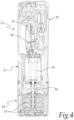
- the electric pump 11 is of the immersion type, is extended vertically in the configuration for use and comprises a containment shell 19, inside which there are:
- the control and actuation assembly 21 is connected to the user interface and comprises communication means 22 of the NFC type.
- the NFC communication means 22 are constituted by an antenna.
- These communication means 22 are electrically connected to the user interface and/or to the management and control element 40 of the device 10.
- the second portion 13 of the device 10 comprises complementary communication means 23 of the NFC type.
- the electric pump 11 comprises mechanical means for the engagement of the second portion 13 of the device 10, which comprises corresponding complementary mechanical means.
- the antenna 22 is arranged proximate to a receptacle 24, which is internal to the electronic section 18 and can be accessed from the outside of the shell 19 but is external to the compartment 20.
- the receptacle 24 is adapted for the insertion of the second portion 13 of the device 10, at least at the complementary NFC communication means 23.
- the complementary NFC communication means 23 are arranged in one end of the second portion 13.
- the NFC communication between the antenna 22 of the control and actuation unit 21 and the complementary communication means 23 of the device 10 it is possible to install the device 10 without the need to physically/electrically connect its second portion 13 to the management and control element 40 and/or to the user interface.
- the user can purchase the electric pump 11 and decide later if and when to purchase and install the device 10.
- the user can install autonomously and easily the device 10 on the electric pump 11.
- the receptacle 24 of the electric pump 11 has such a shape and dimensions that it is substantially shaped complementarily to at least the complementary communication means 23, so as to ensure their easy insertion and coupling of the means inside it.
- the second portion 13 of the device 10 has a substantially quadrangular profile and is substantially flat.
- the pressure transducer 15 is laterally adjacent and electrically connected to the complementary communication means 23 and converts the pressure into an electrical signal which is then sent to the management and control element 40 and/or to the user interface.
- the transducer 15 is an integrated circuit which comprises:
- the device 10 comprises a tube 25, made of plastic material, such as silicone, which extends starting from the transducer 15 toward the bottom of the tank.
- the tube 25 runs along one side of the electric pump 11, inside an adapted duct 26, which has a vertical extension.
- the duct 26 is provided by means of:
- the tube 25 leads into a substantially bell-shaped element 28, with which it communicates and which is arranged substantially at the wet section 16 of the electric pump 11, outside the shell 19.
- the tube 25 contains air, and its particular shape and arrangement, inside the duct 26 and the substantially bell-shaped element 28, and the presence of the substantially bell-shaped element 28 cause the liquid to be unable to rise up to the transducer 15 even when the electric pump 11 is immersed.
- the tube 25 is prevented from being full of water, altering the reading of the transducer 15.
- the electric pump 11 is in fact immersed vertically and during this step air is present inside the substantially bell-shaped element 28 and, due to the shape of said element, is unable to evacuate, remaining trapped inside the assembly constituted by:
- a level variation inside the well/tank causes a pressure variation of the air in the tube 25, which in turn causes a certain stress on the transducer 15.
- the second portion 13 of the device 10 is contained in the electronic section 18 of the electric pump 11, outside the compartment 20, in a subsection 29.
- the transducer 15 is enclosed in the second portion 13, which is comolded around the transducer 15, portion which isolates and renders it impermeable.
- the operation of the device 10 according to the invention is as follows.
- the user records the values of the dimensions of the well/tank in the user interface of the electric pump 11.
- the air pressure sensor in the first portion 12 of the device 10, data-linked by means of a PLC to the management and control element 40 of the device 10 and/or the user interface of the electric pump 11, measures the atmospheric pressure.
- the pressure transducer 15 simultaneously measures the pressure inside the well/tank.
- the management and control element 40 of the device 10 and/or the user interface of the electric pump 11 calculates the difference between these two pressures (ambient and well/tank), returning the value of the level of the well/tank, calculated on the basis of its dimensions entered initially.
- the invention achieves the intended aim and objects, providing a device for detecting the level of a well/tank that can be installed easily by the user and at any time.
- the invention provides a device for detecting the level of a well/tank that is at least partially integrated in the electric pump used in said well/tank and has a small space occupation.
- the invention provides a device for detecting the level of a well/tank that allows to avoid the need to provide a dedicated access to the well/tank for its power supply and its operation, but utilizes the same access to the well/tank that is used by the electric pump with which it is at least partially integrated.
- the invention provides an electric pump which comprises a device for detecting the level of a well/tank that is capable of achieving the aims and objects listed above.
- the materials used may be any according to the requirements and the state of the art.
Landscapes
- Engineering & Computer Science (AREA)
- Mechanical Engineering (AREA)
- General Engineering & Computer Science (AREA)
- Physics & Mathematics (AREA)
- General Physics & Mathematics (AREA)
- Fluid Mechanics (AREA)
- Computer Networks & Wireless Communication (AREA)
- Power Engineering (AREA)
- Structures Of Non-Positive Displacement Pumps (AREA)
- Measurement Of Levels Of Liquids Or Fluent Solid Materials (AREA)
- Control Of Non-Positive-Displacement Pumps (AREA)
- Electrical Discharge Machining, Electrochemical Machining, And Combined Machining (AREA)
Claims (7)
- System zur Erfassung des Pegels eines Brunnens oder Tanks, bestehend aus: eine elektrische Tauchpumpe (11), die eine vertikale Ausdehnung in der Gebrauchskonfiguration aufweist und einen Spalttopf (19) umfasst, in dem sich Folgendes befindet:- einen Nassbereich (16), der einen Einlassabschnitt und einen Auslassabschnitt sowie ein oder mehrere auf einer Welle (34) verkeilte Laufräder (33) umfasst, die jeweils einen eigenen Diffusor aufweisen und zwischen dem Einlassabschnitt und dem Auslassabschnitt angeordnet sind,- einen elektromechanischen Teil (17), der Folgendes umfasst Motormittel (35) für die Bewegung der Welle,- einen elektronischen Teil (18), der ein Fach (20) umfasst, in dem sich eine Einheit (21) zur Steuerung und Betätigung der elektrischen Tauchvorrichtung befindet Pumpe (11) enthalten ist, wobei die Steuer-und Betätigungseinheit (21) die mit einer elektrischen Platine (36) versehen ist, eine Vorrichtung (10), die zumindest teilweise in die elektrische Tauchpumpe (11) integriert ist, um den Pegel eines Brunnens oder Tanks zu erfassen, umfassend:- ein elektronisches Verwaltungs- und Kontrollelement (40),- einen ersten Teil (12), der einen Luftdrucksensor umfasst, der physisch/elektrisch mit dem Steuerungs-und Kontrollelement verbunden ist (40),- einen zweiten Teil (13), der einen Druckwandler (15) umfasst und über eine drahtlose Verbindung mit dem Steuerungs- und Kontrollelement (40) verbunden ist, wobei die Steuer- und Betätigungsbaugruppe (21) ist mit einer Benutzerschnittstelle des elektrischen Tauchgeräts verbunden Pumpe (11) und umfasst Kommunikationsmittel (22) des NFC-Typs, wobei die Kommunikationsmittel (22) elektrisch mit der Benutzerschnittstelle und/oder mit der Verwaltungs-und Steuereinheit verbunden sind Element (40) der Vorrichtung (10), wobei der zweite Teil (13) der Vorrichtung (10) komplementäre Kommunikationsmittel (23) des NFC-Typs umfasst, und die Kommunikationsmittel (22) in der Nähe einer Aufnahme (24) angeordnet sind, wobei sich die Aufnahme (24) innerhalb des elektronischen Abschnitts (18) befindet und von der Außenseite des Gehäuses (19) zugänglich ist, wobei sich die Aufnahme (24) außerhalb des Fachs (20) befindet, wobei der zweite Teil (13) der Vorrichtung (10) in die Aufnahme (24) zumindest an den komplementären Kommunikationsmitteln (23) eingeführt ist
- System zur Erfassung des Pegels eines Brunnens oder Tanks nach Anspruch 1, dadurch gekennzeichnet, dass der Luftdrucksensor über eine Datenverbindung mit dem Verwaltungs- und Steuerelement (40) mittels einer Power Line Communication (PLC) verfügt.
- System zur Erfassung des Pegels eines Brunnens oder Tanks nach Anspruch 1 oder 2, dadurch gekennzeichnet, dass die elektrische Tauchpumpe (11) mechanische Mittel für den Eingriff mit dem zweiten Teil (13) der Vorrichtung (10) umfasst, wobei der zweite Teil (13) der Vorrichtung (10) entsprechende komplementäre mechanische Mittel umfasst.
- System zur Erfassung des Pegels eines Brunnens oder Tanks nach einem oder mehreren der vorhergehenden Ansprüche, dadurch gekennzeichnet, dass der Wandler (15) seitlich neben dem komplementären Kommunikationsmittel (23) angeordnet und mit diesem elektrisch verbunden ist.
- System zur Erfassung des Pegels eines Brunnens oder Tanks nach einem oder mehreren der vorhergehenden Ansprüche, dadurch gekennzeichnet, dass die Vorrichtung (10) ein Rohr (25) umfasst, wobei sich das Rohr (25) ausgehend von dem Messwandler (15) erstreckt, wobei das Rohr (25) entlang einer Seite der elektrischen Tauchpumpe (11) innerhalb eines angepassten Kanals (26) verläuft, wobei der Kanal (26) eine vertikale Erstreckung aufweist und das Rohr (25) in ein im Wesentlichen glockenförmiges Element (28) führt, mit dem es in Verbindung steht, wobei das im Wesentlichen glockenförmige Element (28) im Wesentlichen an dem Nassbereich (16) der elektrischen Tauchpumpe (11) außerhalb des Gehäuses (19) angeordnet ist.
- System zur Erfassung des Pegels eines Brunnens oder Tanks nach einem oder mehreren der vorhergehenden Ansprüche, dadurch gekennzeichnet, dass der zweite Teil (13) der Vorrichtung (10) in dem elektronischen Abschnitt (18) der elektrischen Tauchpumpe (11) außerhalb des Fachs (20) und in einem Unterabschnitt (29) enthalten ist.
- System zur Erfassung des Pegels eines Brunnens oder Tanks nach einem oder mehreren der vorhergehenden Ansprüche, dadurch gekennzeichnet, dass das Steuer-und Kontrollelement (40) der Vorrichtung (10) mit der Benutzerschnittstelle der elektrischen Tauchpumpe (11) verbunden ist und/oder mit dieser zusammenfällt.
Applications Claiming Priority (1)
| Application Number | Priority Date | Filing Date | Title |
|---|---|---|---|
| IT102019000012879A IT201900012879A1 (it) | 2019-07-25 | 2019-07-25 | Dispositivo per la rilevazione del livello di un pozzo/serbatoio ed elettropompa ad immersione con tale dispositivo |
Publications (3)
| Publication Number | Publication Date |
|---|---|
| EP3770562A1 EP3770562A1 (de) | 2021-01-27 |
| EP3770562B1 true EP3770562B1 (de) | 2025-06-04 |
| EP3770562C0 EP3770562C0 (de) | 2025-06-04 |
Family
ID=68733490
Family Applications (1)
| Application Number | Title | Priority Date | Filing Date |
|---|---|---|---|
| EP20184310.9A Active EP3770562B1 (de) | 2019-07-25 | 2020-07-06 | Vorrichtung zur detektion des füllstands eines brunnens/tanks und elektrische tauchpumpe mit der vorrichtung |
Country Status (7)
| Country | Link |
|---|---|
| US (1) | US11708834B2 (de) |
| EP (1) | EP3770562B1 (de) |
| CN (1) | CN112284488B (de) |
| AU (1) | AU2020205224B2 (de) |
| ES (1) | ES3032367T3 (de) |
| IT (1) | IT201900012879A1 (de) |
| RU (1) | RU2020124605A (de) |
Citations (1)
| Publication number | Priority date | Publication date | Assignee | Title |
|---|---|---|---|---|
| US9103344B2 (en) * | 2009-10-05 | 2015-08-11 | Grundfos Management A/S | Submersible pump assembly |
Family Cites Families (17)
| Publication number | Priority date | Publication date | Assignee | Title |
|---|---|---|---|---|
| US7458782B1 (en) * | 2004-01-23 | 2008-12-02 | Spadola Jr Joseph | Computer monitoring system for pumps |
| WO2006091640A2 (en) * | 2005-02-23 | 2006-08-31 | Greg Allen Conrad | Apparatus for monitoring pressure using capillary tubing |
| US20070258827A1 (en) * | 2006-05-02 | 2007-11-08 | Daniel Gierke | Sump pump system |
| CN200950091Y (zh) * | 2006-10-10 | 2007-09-19 | 中国国际海运集装箱(集团)股份有限公司 | 用于罐式集装箱和罐槽车的压力和液位传感器 |
| CN101424273A (zh) * | 2007-10-31 | 2009-05-06 | 卡特彼勒公司 | 冷却风扇驱动系统 |
| CN101248967B (zh) * | 2008-04-17 | 2010-06-02 | 杨协范 | 无害化厕具 |
| US8151694B2 (en) * | 2008-08-01 | 2012-04-10 | Keurig, Incorporated | Beverage forming apparatus with centrifugal pump |
| CN101344419B (zh) * | 2008-08-22 | 2010-07-07 | 佛山市海天调味食品有限公司 | 一种储液罐的液位检测系统 |
| US20110202194A1 (en) * | 2010-02-15 | 2011-08-18 | General Electric Company | Sub-metering hardware for measuring energy data of an energy consuming device |
| WO2012033880A1 (en) * | 2010-09-08 | 2012-03-15 | Direct Drivehead, Inc. | System and method for controlling fluid pumps to achieve desired levels |
| EP3910121A1 (de) * | 2012-03-14 | 2021-11-17 | South East Water Corporation | Überwachungs- und steuerungsvorrichtung eines pneumatischen abwassersystems |
| US20130272898A1 (en) * | 2012-04-17 | 2013-10-17 | Schlumberger Technology Corporation | Instrumenting High Reliability Electric Submersible Pumps |
| KR101255352B1 (ko) * | 2012-04-26 | 2013-04-16 | 한국지질자원연구원 | 해안 지하수 모니터링 시스템 |
| ITPD20120373A1 (it) * | 2012-12-11 | 2014-06-12 | Dab Pumps Spa | Trasduttore di pressione |
| CN204729318U (zh) * | 2015-06-16 | 2015-10-28 | 合肥工业大学 | 智能感知型潜水电泵 |
| EP3315784B1 (de) * | 2016-10-25 | 2022-10-12 | Grundfos Holding A/S | Tauchpumpenaggregat und verfahren zum betreiben eines tauchpumpenaggregates |
| EP3489517B1 (de) * | 2017-11-24 | 2022-06-01 | Xylem Europe GmbH | Pumpe und verfahren zur steuerung einer pumpe |
-
2019
- 2019-07-25 IT IT102019000012879A patent/IT201900012879A1/it unknown
-
2020
- 2020-07-06 ES ES20184310T patent/ES3032367T3/es active Active
- 2020-07-06 EP EP20184310.9A patent/EP3770562B1/de active Active
- 2020-07-14 AU AU2020205224A patent/AU2020205224B2/en active Active
- 2020-07-20 US US16/933,033 patent/US11708834B2/en active Active
- 2020-07-21 CN CN202010705780.5A patent/CN112284488B/zh active Active
- 2020-07-24 RU RU2020124605A patent/RU2020124605A/ru unknown
Patent Citations (1)
| Publication number | Priority date | Publication date | Assignee | Title |
|---|---|---|---|---|
| US9103344B2 (en) * | 2009-10-05 | 2015-08-11 | Grundfos Management A/S | Submersible pump assembly |
Also Published As
| Publication number | Publication date |
|---|---|
| AU2020205224A1 (en) | 2021-02-11 |
| AU2020205224B2 (en) | 2025-03-13 |
| CN112284488B (zh) | 2025-04-25 |
| ES3032367T3 (en) | 2025-07-17 |
| US11708834B2 (en) | 2023-07-25 |
| US20210025398A1 (en) | 2021-01-28 |
| EP3770562A1 (de) | 2021-01-27 |
| EP3770562C0 (de) | 2025-06-04 |
| CN112284488A (zh) | 2021-01-29 |
| IT201900012879A1 (it) | 2021-01-25 |
| RU2020124605A (ru) | 2022-01-24 |
Similar Documents
| Publication | Publication Date | Title |
|---|---|---|
| US6981399B1 (en) | Method for detecting a differential pressure | |
| US6282953B1 (en) | Solid state fuel level sensing | |
| CN105806445B (zh) | 多变量导波雷达探针 | |
| US6923057B2 (en) | Liquid level sending unit with flexible sensor board | |
| EP3201574B1 (de) | Magnetischer flussmesser mit dampfdurchlässigkeitssensor | |
| CN107975481B (zh) | 潜水泵机组和用于运行潜水泵机组的方法 | |
| KR102442957B1 (ko) | Pcb에 온도센서가 실장된 전자식 수도 미터기 | |
| EP1567762B2 (de) | Kraftstofffilter für dieselmotoren mit common-rail-hochdruckdirekteinspritzung und dergleichen | |
| EP3770562B1 (de) | Vorrichtung zur detektion des füllstands eines brunnens/tanks und elektrische tauchpumpe mit der vorrichtung | |
| US8567242B1 (en) | Pressure sensor venting system | |
| US11976958B2 (en) | Capacitive liquid level sensor and liquid sensor assembly | |
| EP4073345B1 (de) | Unterwasseranschluss | |
| KR101734192B1 (ko) | 수위감지장치 | |
| CN104997409A (zh) | 一种咖啡机 | |
| KR20120000414U (ko) | 정전용량 변화 감지방식의 수위센서 | |
| US20150276455A1 (en) | Measurement arrangement and dishwasher containing a measurement arrangement | |
| WO2019196789A1 (zh) | 新型水位传感器及洗衣机 | |
| IT202100017633A1 (it) | Dispositivo di rilevazione a galleggiante per monitorare la quantità di un liquido in un contenitore. | |
| WO2013089316A1 (ko) | 정전용량 방식의 레벨 센서 및 레벨 감지 방법 | |
| IT201900012849A1 (it) | Elettropompa con accessori personalizzabili | |
| AU2014100363A4 (en) | Automotive fuel gauge senor | |
| WO2019190445A2 (en) | Flushing unit control system with independent level sensor | |
| AU2019284047A1 (en) | Electronic devices |
Legal Events
| Date | Code | Title | Description |
|---|---|---|---|
| PUAI | Public reference made under article 153(3) epc to a published international application that has entered the european phase |
Free format text: ORIGINAL CODE: 0009012 |
|
| STAA | Information on the status of an ep patent application or granted ep patent |
Free format text: STATUS: THE APPLICATION HAS BEEN PUBLISHED |
|
| AK | Designated contracting states |
Kind code of ref document: A1 Designated state(s): AL AT BE BG CH CY CZ DE DK EE ES FI FR GB GR HR HU IE IS IT LI LT LU LV MC MK MT NL NO PL PT RO RS SE SI SK SM TR |
|
| AX | Request for extension of the european patent |
Extension state: BA ME |
|
| STAA | Information on the status of an ep patent application or granted ep patent |
Free format text: STATUS: REQUEST FOR EXAMINATION WAS MADE |
|
| 17P | Request for examination filed |
Effective date: 20210607 |
|
| RBV | Designated contracting states (corrected) |
Designated state(s): AL AT BE BG CH CY CZ DE DK EE ES FI FR GB GR HR HU IE IS IT LI LT LU LV MC MK MT NL NO PL PT RO RS SE SI SK SM TR |
|
| RIN1 | Information on inventor provided before grant (corrected) |
Inventor name: SINICO, FRANCESCO Inventor name: SPORTOLETTI, SERGIO Inventor name: CIUCHI, FRANCESCO Inventor name: TAZIOLI, STEFANO |
|
| STAA | Information on the status of an ep patent application or granted ep patent |
Free format text: STATUS: EXAMINATION IS IN PROGRESS |
|
| 17Q | First examination report despatched |
Effective date: 20230105 |
|
| P01 | Opt-out of the competence of the unified patent court (upc) registered |
Effective date: 20230515 |
|
| GRAP | Despatch of communication of intention to grant a patent |
Free format text: ORIGINAL CODE: EPIDOSNIGR1 |
|
| STAA | Information on the status of an ep patent application or granted ep patent |
Free format text: STATUS: GRANT OF PATENT IS INTENDED |
|
| RIC1 | Information provided on ipc code assigned before grant |
Ipc: H02K 5/132 20060101ALI20250318BHEP Ipc: F04D 15/02 20060101ALI20250318BHEP Ipc: F04D 13/08 20060101ALI20250318BHEP Ipc: G01F 23/18 20060101AFI20250318BHEP |
|
| INTG | Intention to grant announced |
Effective date: 20250326 |
|
| GRAS | Grant fee paid |
Free format text: ORIGINAL CODE: EPIDOSNIGR3 |
|
| GRAA | (expected) grant |
Free format text: ORIGINAL CODE: 0009210 |
|
| STAA | Information on the status of an ep patent application or granted ep patent |
Free format text: STATUS: THE PATENT HAS BEEN GRANTED |
|
| AK | Designated contracting states |
Kind code of ref document: B1 Designated state(s): AL AT BE BG CH CY CZ DE DK EE ES FI FR GB GR HR HU IE IS IT LI LT LU LV MC MK MT NL NO PL PT RO RS SE SI SK SM TR |
|
| REG | Reference to a national code |
Ref country code: GB Ref legal event code: FG4D |
|
| REG | Reference to a national code |
Ref country code: CH Ref legal event code: EP |
|
| REG | Reference to a national code |
Ref country code: DE Ref legal event code: R096 Ref document number: 602020052194 Country of ref document: DE |
|
| REG | Reference to a national code |
Ref country code: IE Ref legal event code: FG4D |
|
| PGFP | Annual fee paid to national office [announced via postgrant information from national office to epo] |
Ref country code: GB Payment date: 20250612 Year of fee payment: 6 |
|
| REG | Reference to a national code |
Ref country code: ES Ref legal event code: FG2A Ref document number: 3032367 Country of ref document: ES Kind code of ref document: T3 Effective date: 20250717 |
|
| P04 | Withdrawal of opt-out of the competence of the unified patent court (upc) registered |
Free format text: CASE NUMBER: APP_31797/2025 Effective date: 20250702 |
|
| U01 | Request for unitary effect filed |
Effective date: 20250630 |
|
| U07 | Unitary effect registered |
Designated state(s): AT BE BG DE DK EE FI FR IT LT LU LV MT NL PT RO SE SI Effective date: 20250704 |
|
| U20 | Renewal fee for the european patent with unitary effect paid |
Year of fee payment: 6 Effective date: 20250707 |
|
| PGFP | Annual fee paid to national office [announced via postgrant information from national office to epo] |
Ref country code: ES Payment date: 20250807 Year of fee payment: 6 |
|
| PG25 | Lapsed in a contracting state [announced via postgrant information from national office to epo] |
Ref country code: GR Free format text: LAPSE BECAUSE OF FAILURE TO SUBMIT A TRANSLATION OF THE DESCRIPTION OR TO PAY THE FEE WITHIN THE PRESCRIBED TIME-LIMIT Effective date: 20250905 Ref country code: NO Free format text: LAPSE BECAUSE OF FAILURE TO SUBMIT A TRANSLATION OF THE DESCRIPTION OR TO PAY THE FEE WITHIN THE PRESCRIBED TIME-LIMIT Effective date: 20250904 |
|
| PG25 | Lapsed in a contracting state [announced via postgrant information from national office to epo] |
Ref country code: PL Free format text: LAPSE BECAUSE OF FAILURE TO SUBMIT A TRANSLATION OF THE DESCRIPTION OR TO PAY THE FEE WITHIN THE PRESCRIBED TIME-LIMIT Effective date: 20250604 |
|
| PG25 | Lapsed in a contracting state [announced via postgrant information from national office to epo] |
Ref country code: HR Free format text: LAPSE BECAUSE OF FAILURE TO SUBMIT A TRANSLATION OF THE DESCRIPTION OR TO PAY THE FEE WITHIN THE PRESCRIBED TIME-LIMIT Effective date: 20250604 |
|
| PG25 | Lapsed in a contracting state [announced via postgrant information from national office to epo] |
Ref country code: RS Free format text: LAPSE BECAUSE OF FAILURE TO SUBMIT A TRANSLATION OF THE DESCRIPTION OR TO PAY THE FEE WITHIN THE PRESCRIBED TIME-LIMIT Effective date: 20250904 |
|
| PG25 | Lapsed in a contracting state [announced via postgrant information from national office to epo] |
Ref country code: IS Free format text: LAPSE BECAUSE OF FAILURE TO SUBMIT A TRANSLATION OF THE DESCRIPTION OR TO PAY THE FEE WITHIN THE PRESCRIBED TIME-LIMIT Effective date: 20251004 |
|
| PG25 | Lapsed in a contracting state [announced via postgrant information from national office to epo] |
Ref country code: SM Free format text: LAPSE BECAUSE OF FAILURE TO SUBMIT A TRANSLATION OF THE DESCRIPTION OR TO PAY THE FEE WITHIN THE PRESCRIBED TIME-LIMIT Effective date: 20250604 |
|
| PG25 | Lapsed in a contracting state [announced via postgrant information from national office to epo] |
Ref country code: CZ Free format text: LAPSE BECAUSE OF FAILURE TO SUBMIT A TRANSLATION OF THE DESCRIPTION OR TO PAY THE FEE WITHIN THE PRESCRIBED TIME-LIMIT Effective date: 20250604 |
|
| PG25 | Lapsed in a contracting state [announced via postgrant information from national office to epo] |
Ref country code: SK Free format text: LAPSE BECAUSE OF FAILURE TO SUBMIT A TRANSLATION OF THE DESCRIPTION OR TO PAY THE FEE WITHIN THE PRESCRIBED TIME-LIMIT Effective date: 20250604 |
|
| REG | Reference to a national code |
Ref country code: CH Ref legal event code: H13 Free format text: ST27 STATUS EVENT CODE: U-0-0-H10-H13 (AS PROVIDED BY THE NATIONAL OFFICE) Effective date: 20260224 |
|
| PG25 | Lapsed in a contracting state [announced via postgrant information from national office to epo] |
Ref country code: MC Free format text: LAPSE BECAUSE OF FAILURE TO SUBMIT A TRANSLATION OF THE DESCRIPTION OR TO PAY THE FEE WITHIN THE PRESCRIBED TIME-LIMIT Effective date: 20250604 |
|
| PLBE | No opposition filed within time limit |
Free format text: ORIGINAL CODE: 0009261 |
|
| STAA | Information on the status of an ep patent application or granted ep patent |
Free format text: STATUS: NO OPPOSITION FILED WITHIN TIME LIMIT |
|
| REG | Reference to a national code |
Ref country code: CH Ref legal event code: L10 Free format text: ST27 STATUS EVENT CODE: U-0-0-L10-L00 (AS PROVIDED BY THE NATIONAL OFFICE) Effective date: 20260416 |
|
| PG25 | Lapsed in a contracting state [announced via postgrant information from national office to epo] |
Ref country code: CH Free format text: LAPSE BECAUSE OF NON-PAYMENT OF DUE FEES Effective date: 20250731 |