EP3770124A1 - Device and method for the production of glass ribbons - Google Patents
Device and method for the production of glass ribbons Download PDFInfo
- Publication number
- EP3770124A1 EP3770124A1 EP20186538.3A EP20186538A EP3770124A1 EP 3770124 A1 EP3770124 A1 EP 3770124A1 EP 20186538 A EP20186538 A EP 20186538A EP 3770124 A1 EP3770124 A1 EP 3770124A1
- Authority
- EP
- European Patent Office
- Prior art keywords
- guide body
- nozzle opening
- glass
- tank
- nozzle
- Prior art date
- Legal status (The legal status is an assumption and is not a legal conclusion. Google has not performed a legal analysis and makes no representation as to the accuracy of the status listed.)
- Pending
Links
Images


Classifications
-
- C—CHEMISTRY; METALLURGY
- C03—GLASS; MINERAL OR SLAG WOOL
- C03B—MANUFACTURE, SHAPING, OR SUPPLEMENTARY PROCESSES
- C03B17/00—Forming molten glass by flowing-out, pushing-out, extruding or drawing downwardly or laterally from forming slits or by overflowing over lips
- C03B17/06—Forming glass sheets
- C03B17/061—Forming glass sheets by lateral drawing or extrusion
- C03B17/062—Forming glass sheets by lateral drawing or extrusion combined with flowing onto a solid or gaseous support from which the sheet is drawn
-
- C—CHEMISTRY; METALLURGY
- C03—GLASS; MINERAL OR SLAG WOOL
- C03B—MANUFACTURE, SHAPING, OR SUPPLEMENTARY PROCESSES
- C03B17/00—Forming molten glass by flowing-out, pushing-out, extruding or drawing downwardly or laterally from forming slits or by overflowing over lips
- C03B17/06—Forming glass sheets
- C03B17/067—Forming glass sheets combined with thermal conditioning of the sheets
-
- C—CHEMISTRY; METALLURGY
- C03—GLASS; MINERAL OR SLAG WOOL
- C03B—MANUFACTURE, SHAPING, OR SUPPLEMENTARY PROCESSES
- C03B17/00—Forming molten glass by flowing-out, pushing-out, extruding or drawing downwardly or laterally from forming slits or by overflowing over lips
- C03B17/06—Forming glass sheets
- C03B17/068—Means for providing the drawing force, e.g. traction or draw rollers
-
- Y—GENERAL TAGGING OF NEW TECHNOLOGICAL DEVELOPMENTS; GENERAL TAGGING OF CROSS-SECTIONAL TECHNOLOGIES SPANNING OVER SEVERAL SECTIONS OF THE IPC; TECHNICAL SUBJECTS COVERED BY FORMER USPC CROSS-REFERENCE ART COLLECTIONS [XRACs] AND DIGESTS
- Y02—TECHNOLOGIES OR APPLICATIONS FOR MITIGATION OR ADAPTATION AGAINST CLIMATE CHANGE
- Y02P—CLIMATE CHANGE MITIGATION TECHNOLOGIES IN THE PRODUCTION OR PROCESSING OF GOODS
- Y02P40/00—Technologies relating to the processing of minerals
- Y02P40/50—Glass production, e.g. reusing waste heat during processing or shaping
- Y02P40/57—Improving the yield, e-g- reduction of reject rates
Definitions
- the invention relates generally to glass manufacture.
- the invention relates to the production of glass ribbons in the down-draw process.
- the down-draw process can be used to produce strips of glass with completely identical surfaces.
- the down-draw process is also particularly suitable for the production of very thin glasses and wide glass ribbons.
- a draw tank ensures that the glass distribution is evened up to a nozzle slot through which the glass exits at the hot forming temperature.
- the manufactured products have a poorer surface quality, in particular with the fine waviness due to the short dwell time of the glass in the area of the drawing bulb. Unevenness that occurs on the tear-off edge of the glass at the nozzle outlet cannot be effectively healed in this way.
- the method requires a slot shape of the nozzle, which has to be adapted to the particular thickness to be produced. In the event of a change in the thickness formats to be produced, this leads to downtimes due to set-up times and increased material requirements.
- the guide body can influence the flow of the glass melt in the drawing tank, so that thickness fluctuations and glass defects, such as streaks in particular, can occur.
- the invention is therefore based on the object of an arrangement which is improved with regard to the dimensional accuracy of the glass ribbon and the avoidance of glass defects for drawing glass ribbons and a corresponding procedure.
- This object is achieved by the subject matter of the independent claims.
- Advantageous further developments are given in the respective dependent claims.
- the invention provides a device for drawing glass ribbons from a glass melt, the device having a drawing tank for receiving a glass melt, which has a lower, preferably slit or slot-shaped nozzle opening through which the glass melt can exit downwards.
- the device also has a guide body which protrudes downward from the nozzle opening of the draw tank.
- the guide body is held at a distance from the edges of the nozzle opening, so that two nozzle gaps are formed between the guide body and the edges of the nozzle opening.
- the guide body is suspended or supported in a cantilevered manner along the nozzle opening at two opposite ends.
- the guide body has a fine-grain stabilized metal as the carrier material.
- the guide body extends in a self-supporting manner along the nozzle slot, that is to say mountings or struts for the guide body are avoided in the interior of the drawing tank filled with the glass melt, the flow of the glass melt is not influenced by such structures. This results in a very even glass flow and a correspondingly homogeneous thickness of the removed glass ribbon.
- bending moments act on the guide body due to the suspension at the end, which can lead to creep deformation of the guide body. This creep deformation is counteracted with the fine-grain stabilized metal in the supporting structure of the guide body.
- a method for producing a glass ribbon in which a glass melt is fed to a draw tank, the draw tank having a lower nozzle opening for the exit of the molten glass, a guide body being arranged in the nozzle opening which protrudes downward from the nozzle opening of the draw tank, the guide body being held at a distance from the edges of the nozzle opening, see above that between the guide body and the edges of the nozzle opening two nozzle gaps are formed, the guide body being suspended cantilevered at two opposite lateral ends and along the nozzle opening or along its longitudinal direction, and the molten glass exiting the drawing tank in two partial flows from the nozzle gaps and runs along the part of the guide body protruding from the nozzle opening, the partial flows merging at the lower end of the guide body in an onion from which the glass ribbon is pulled off, and the pulling off of the glass ribbon exerts a tensile force on the guide body, which is caused by the suspension movement of the guide body is caught at its lateral ends.
- the down-draw process with guide body enables an increased glass throughput compared to drawing glass strips without a guide body due to the larger drawing tank opening and better surface quality on the product. This is caused by the extended dwell time on the guide body after the nozzle exit.
- Another advantage is that in this case it is possible to work with an increased temperature in the nozzle area, because the shaping viscosities 10 3.5 dPa ⁇ s to 10 4.5 dPa ⁇ s do not need to be reached in the nozzle slot but only at the lower edge of the guide body. In the case of glasses and glass ceramics that are sensitive to crystallization, this is very advantageous and leads to increased yields.
- the advantages of the down-draw process, whether with or without a guide body, compared to the overflow fusion process with an overflow trough on ceramic, are that there is no or only a reduced central streak (which is created by the ceramic of the trough).
- the homogeneity of the glass composition along the thickness is therefore very high. Due to the self-supporting suspension provided here, no inhomogeneities in the glass are caused by the guide body either.
- the process offers a high degree of flexibility, because after the process has been stopped, the tools can be changed and then reused.
- the border thickness is reduced in comparison, which, among other things, deflects the tape into the horizontal Further processing after the cooling furnace exit is simplified and, in particular, the economy and yield are increased.
- these alloys are no longer completely stable against creep processes, which leads to an increasing deformation of the tools over time.
- the molding temperature is a temperature at which the glass has a viscosity of 10 4 dPa ⁇ s.
- the drawing tank, slot nozzle and guide body form a system that influences the thickness distribution (longitudinal and transverse distribution) of the viscous glass.
- a good long-term stability of this system is very advantageous here.
- the arrangement described here enables the downdraw process with guide bodies to be used, even with high drawing forces.
- Particularly suitable metals of the fine-grain stabilized support material are platinum and platinum alloys, in particular Pt, PtRh, PtAu, PtRhAu, PtIr, preferably in the above-mentioned percentages.
- the carrier material can be produced by melt metallurgy or powder metallurgy.
- To Fine grain stabilization nanoparticles are preferably used.
- a well-suited material for the fine-grain particles is ZrO 2 .
- the fine-grain particles can be added and distributed in the melt, in particular when the metal is melted down or the alloy is melted together.
- fine-grain stabilized elements can also be manufactured using powder metallurgy. For this purpose, metal particles and the fine-grain particles are mixed and the mixture is sintered together.
- a guide body made entirely of fine-grain stabilized metal is particularly stable.
- the guide body can be in several parts, with at least one of the parts or elements being made from fine-grain stabilized metal.
- the guide body is a sandwich construction made of fine-grain stabilized metal and another material.
- the further material can be a metal or a non-metallic high-temperature-resistant material.
- the guide body therefore comprises at least one ceramic element which is coated with the fine-grain stabilized metal.
- the variant of a guide body made entirely of fine-grain stabilized metal has the advantage of increased stability. Disadvantages are increased material costs and reduced weldability due to the floating effects of the stabilizing materials and the increased brittleness.
- the further variant with a sandwich structure of the guide body or a combination with non-fine-grain stabilized metal is preferable in terms of material costs and weldability, but the expected service life is somewhat lower.
- Suppliers of these stabilized materials are e.g. Umicore, Furuya, Heraeus, Tanaka, each with their own versions of these materials (Umicore e.g. PtRh10 FKS Rigilit, PtRh10 FKS Saeculit - Heraeus e.g. PtRh10 DPH or DPH-A, etc.).
- Highly creep-resistant noble metals such as pure iridium are less suitable because they are not resistant to oxidation.
- Fig. 1 shows parts of a device 1 for drawing glass ribbons 3 from a glass melt 5.
- the device 1 has a drawing tank 7 for receiving a glass melt 5, which has a nozzle opening 9 at its lower end through which the glass melt 5 can exit downwards.
- a guide body 11 is arranged in the draw tank 7 and protrudes downward from the nozzle opening 9 of the draw tank 7. With the guide body 11 guided through the nozzle opening, the nozzle opening 9 is subdivided into two nozzle gaps 94, 96.
- the glass melt 5 exits in two partial flows 50, 52 through the nozzle gaps 94, 96. These run down along the guide body 11 and unite at the lower end of the part 100 of the guide body 11 protruding from the nozzle opening 9.
- This area in which the two partial flows combine and from which the glass ribbon is formed by pulling it off is called a drawing bulb 15 designated.
- a drawing bulb 15 designated.
- the thickness of the glass ribbon 3 is reduced by pulling out the glass.
- the glass becomes colder and correspondingly more viscous as the distance from the nozzle opening 9 increases, until it solidifies.
- the guide body 11 protrudes at least 30 mm, preferably at least 80 mm, from the nozzle opening 9. In this way a good distribution of the glass melt on the guide body 11 is made possible, so that thickness fluctuations in the glass ribbon are suppressed.
- the guide body 11 has a resistance body 101, which is arranged inside the draw tank 7 and represents a widened section at the upper end of the guide body 11, which has the flow cross-section for the glass melt 5 opposite below the adjoining part of the guide body 11 narrows.
- This lower part of the guide body 11 can be referred to as a sword or blade 103.
- the guide body 11 comprises a resistance body 101 and a blade 103 arranged below the resistance body 101, the resistance body 101 having a greater width than the blade 103 in order to narrow the flow cross-section in the drawing tank 7.
- the distance from the nozzle opening 9 to the lower edge of the flow resistance or of the resistance body 101 is generally preferably at least 3 mm, preferably at least 8 mm.
- a pulling device 17 can be provided. This can include, for example, one or more pairs of driven rollers.
- a tensile force is exerted on the glass ribbon 3, which typically acts at least for the most part on the guide body 11.
- This tensile force acts in the same direction and in addition to the weight force.
- the guide body 11 can be held in the draw tank with struts around which the glass melt 5 flows.
- Such a holder is mechanically very stable. However, it has been shown that this can have negative effects on the quality of the glass ribbon 3.
- the guide body 11 is suspended in a self-supporting manner along at least a central section of the nozzle opening 9.
- a glass ribbon 3 is formed during drawing, which has a central area of uniform thickness and two edge-side borders with a greater thickness compared to the central area, the guide body 11 being suspended so that it is at least along the section the nozzle opening at which the central region of uniform thickness is formed is cantilevered.
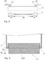
- Fig. 2 shows a guide body 11 with suspension according to an embodiment and a glass ribbon 3 in cross section.
- the glass ribbon 3 has a central region 30 along which the thickness of the glass ribbon 3 does not change or changes only slightly, as well as edging 31, 33 on the edge.
- the central region 30 forms the so-called quality range from which the glass products to be manufactured are manufactured.
- the braids 31, 33 are cut off and the glass of the braids can be melted down again and fed to the drawing tank 7.
- the guide body 11 is suspended with a holder 19.
- the support areas 21 on which the guide body 11 transmits the forces acting on it to the holder 19 are arranged so far on the edge that these areas lie outside the quality range or the central area 30.
- the guide body 11 is self-supporting between these areas 21, so there are no further suspension points.
- Fig. 3 shows a specific configuration of this embodiment.
- Fig. 3 is a schematic sectional view through the draw tank with the cutting direction centered along the nozzle opening 9 with a vertical sectional plane.
- support elements 23 are inserted, on which the guide body 11 again rests.
- the support elements 23 can be inserted in the area of the nozzle opening 9, as shown, and span the nozzle opening 9.
- the points of support of the guide body 11 on the support elements 23 form the holding areas, in particular support areas 21 for the guide body 11.
- one embodiment of the invention provides for the guide body 11 in the drawing nozzle to rest on holding elements 23 and to be held in a cantilevered manner between the support areas 21 on the holding elements 23.
- the guide body 11 is generally preferably designed in such a way that it does not bend significantly when the glass ribbon is pulled from the draw tank 7 with a tensile force of greater than 100 N per 1000 mm of glass ribbon width.
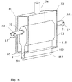
- Fig. 4 shows schematically an example of a further, particularly preferred embodiment.
- the draw tank 7 is shown here in a perspective view. This illustration also shows an inlet 74 through which the glass melt is introduced into the drawing tank 7.
- the draw tank 7 is laterally by two in this example End plates 71 closed.
- the end plates 71 have openings 72 through which cantilevers or cantilever arms 110, 111 of the guide body 11 protrude. These cantilever arms 110, 111 rest on holders 19 arranged outside of the draw tank 7.
- the support areas 21, between which the guide body 11 is suspended in a self-supporting manner, are therefore outside the drawing tank 7 and thus also outside the glass melt running downward in the drawing tank 7.
- one embodiment of the device for drawing glass strips provides that the guide body 11 is held outside the drawing tank 7.
- the guide body runs in a self-supporting manner along the entire interior of the draw tank 7. In this way it is avoided that the glass flow is influenced by the holder. This ensures a constant glass quality and avoids the formation of streaks.
- This arrangement also has another advantage.
- the holder of the guide body 11 is decoupled from the draw tank 7 in such a way that parts of the draw tank can be changed without removing the guide body 11.
- the floor panels 97, 98 or, more generally, parts of the wall which comprise the floor panels can be exchanged without removing the guide body 11.
- the base plates can be exchanged in such a way that the width of the nozzle opening 9 changes without the guide body 11 having to be moved during the exchange.
- the draw tank is designed so that the parts of the draw tank 7 that form the nozzle opening 9 can be exchanged while the guide body 11 remains in its holder in place.
- the guide body 11 comprises a fine-grain stabilized metal.
- Fig. 5 shows a diagram with measured values of the creep rate v of various alloys suitable for glass production as a function of an applied mechanical stress ⁇ . All measured values were recorded at a temperature of the material of 1400 ° C.
- the curve (a) shows the measured values for a conventional, not fine-grain stabilized platinum-rhodium alloy.
- Curves (b) and (c) are measured values of two different fine-grain stabilized alloys. At a mechanical stress of 5 MPa, the creep rate of the alloy for curve (b) is already two orders of magnitude below that of the non-fine-grain stabilized material.
- fine-grain stabilized alloys can be influenced and adjusted by the amount, type and size of the particles added for stabilization.
- the use of a fine-grain stabilized alloy for the guide body makes it possible to process glasses with a shaping temperature of more than 1100 ° C., even of 1400 ° C. and more, as shown in FIG Fig. 5 can be seen.
- fine-grain stabilized metals are the materials sold under the names PtRh10 FKS Rigilit, PtRh10 FKS Saeculit from Umicore and PtRh10 DPH or DPH-A from Heraeus.
- Pt, PtAu, PtRhAu and PtIr can also be used for the fine-grain stabilized material.
- the stabilizing particles can be or comprise oxidic particles.
- ZrO 2 particles are suitable.
- Highly creep-resistant noble metals such as pure iridium are not preferred as an alternative, since these are generally less resistant to oxidation.
- the guide body 11 is made entirely of fine-grain stabilized material. This achieves a particularly high creep resistance at high temperatures. However, they increase Material costs. The welding of parts made of fine-grain stabilized alloys is not easy either, since the stabilizing particles can float, which can significantly reduce the stability in the welding area. These stabilized metals are also more brittle than non-stabilized materials due to the particles in their structure.
- a multi-part guide body 11 which has at least one element made of fine-grain stabilized metal.
- a multi-part construction is advantageous due to the lower material costs, but the service life is somewhat shorter.
- the guide body can in particular be a sandwich construction made of fine-grain stabilized metal and at least one further material. Creeping deformation is particularly relevant in areas subject to high tensile loads. Therefore, according to a development, it is provided that the guide body 11 is in several parts, a lower element of the guide body 11 being an element made of fine-grain stabilized material.
- the term “lower part” relates to the position of the part when the guide body 11 is mounted.
- the guide body 11 comprises an upper element 112, here thickened, and a lower element 114, which also comprises the part 100 of the guide body 11 protruding from the nozzle opening 9.
- This lower element 114 is tensile loaded by the dead weight of the guide body 11 and the force exerted by the pulling device 17 on the glass ribbon.
- the element 112 forms a resistance body 101 due to its thickening.
- the lower part 100 protruding from the nozzle opening is shaped as a sheet 103.
- the shape of the tools can be optimized to improve their stability.
- the pressure curve can also be adapted and the mixing of the glass melt improved.
- the guide body 11 is designed, for example, as a simple, too thin sheet metal within the nozzle slot, then under high load, for example at greater than 100 N per 1000 mm glass ribbon width and a high temperature of 1200 ° C and more, instability can arise along and across the drawing direction. This leads to fluctuations in the nozzle slot width and thus to instabilities in the drawing process. With the help of an adaptation of the shape of the guide body 11, the stability can be increased sufficiently.
- Fig. 6 shows an embodiment of a device 1 for drawing glass strips 3 with a guide body 11, which is also like the one in FIG Fig. 4 example shown has a thickened upper part. This upper part is in the example Fig. 6 mushroom-shaped. Also the example of Fig. 6 also shows a multi-part guide body 11. In this case, however, the individual elements are not placed on top of one another, a lower element 114 being made of fine-grain-stabilized metal. This in Fig. 6
- the example shown of the guide body 11 is rather constructed as a sandwich construction.
- a guide body 11 is generally provided which has an inner part 115 which is surrounded by a cladding 117.
- the lining is preferably made of fine-grain stabilized metal.
- the guide body 11 can thus comprise at least one ceramic element which is coated with the fine-grain stabilized metal.
- the inner part 115 is made of a ceramic material and the cladding 117 is made of fine-grain-stabilized metal.
- the guide body comprises an inner part 115 made of iridium, which is surrounded by a cladding 117.
- the cladding 117 can then in turn comprise a fine-grain stabilized metal, at least in tensile stressed areas.
- the pressure conditions can be set via the geometry of the system consisting of the nozzle slot and flow resistance within the drawing tank.
- the flow resistance together with the static pressure, ensures a desired overpressure at the end of the drawing tank or at the nozzle opening. This ensures a homogeneous glass distribution on the sword body.
- the pressure drop can be set so that the glass melt is at the The nozzle outlet hardly widens, thereby avoiding wetting of the lower edge of the nozzle slot.
- Fig. 7 shows an example of a further embodiment.
- This example is based in principle on the fact that above the guide body 11 protruding from the nozzle opening 9 and with an intermediate space to this guide body 11 protruding from the nozzle opening 9, a further guide body 12, preferably likewise cantilevered within the draw tank 7, is arranged.
- This further guide body 12 is used for additional thorough mixing of the glass melt 5.
- the flow resistance for the glass melt 5 can also be influenced with such an additional guide body 12.
- the setting of the nozzle slot width also influences the size of the tear-off angle at the lower edge of the nozzle. If this angle is too small, wetting with glass below the nozzle edge can occur, which can lead to crystallization and glass defects.
- one embodiment of the invention therefore provides that the pressure drop of the glass melt 5 in the draw tank is set in such a way that wetting of areas of the underside of the draw tank 7 adjoining the nozzle opening 9 is avoided. In addition to the position and shape of the guide body (s), the pressure drop can also be adjusted by the temperature of the glass melt.
- Another advantage of an internal flow resistance in the form of the guide body 11, possibly also a further guide body 12 in the draw tank 7, is the reduced sensitivity of the glass quality (e.g. with regard to thickness fluctuations) in the case of existing or arising tool deformations due to tool life during long-term use (e.g. compensation from draw tank dents, lowering of the sword body, inclined position of the sword body, ...) because a kind of compensation volume is created below the internal flow resistance in which the transverse distribution of the glass mass can homogenize before it flows through the nozzle slot (only if the thickness ratio sword blade / flow resistance in the drawing tank ⁇ 1 ).
- the service life of the tools can be increased by at least one order of magnitude, which is reflected in the stabilization of the product quality and also in cost savings. Furthermore, an increase in the bandwidths is also possible, since geometrical adjustments and the use of stabilized alloys have the effect that the drawing bodies bend or creep less strongly when the tensile loads are increased.
- the mechanically stabilizing thickening of the guide body 11 in the draw tank 7, as shown in the exemplary embodiments shown so far, also generally contributes to the longer service life. Without being restricted to the specific exemplary embodiments, a further development provides that the guide body 11 has a greater thickness within the draw tank 7 than at the nozzle opening 9. In the case of the in FIG Fig. 7
- the thickening 118 which also forms a resistance body 101, is cylindrical.
- a tapering tear-off edge 13 at the lower end of the guide body 11 is advantageous.
- the tear-off edge 13 forms a cutting edge.
- the surfaces 130, 131 opening into the tear-off edge 13 can, however, be flat, convex or concave. In the example of Fig. 7 the surfaces 130, 131 are flat.
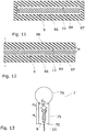
- FIG. 11 shows an example of a guide body which has a plate-shaped thickening 118 so that the upper end of the guide body 11 is T-shaped.
- the example also shows surfaces 130, 131 which open into the tear-off edge 13 and are concave here.
- Fig. 9 shows an embodiment in which the guide body 11 in the interior of the draw tank 7 is not thickened compared to its thickness in the region of the nozzle gap. Rather, the guide body 11 here has the shape of a sword or a plate with an essentially constant thickness and a cutting edge opening into a tear-off edge 13 with the surfaces 130, 131 at its lower end. Among other things, this embodiment has the advantage that the guide body 11 can easily be removed from the nozzle opening 9 with suitable suspension.
- Extending part of the guide body 11 preferably has a thickness in the range from 0.5 mm to 20 mm.
- the guide body 11 it is also not essential in all embodiments of the device for the guide body 11 to extend into the interior of the draw tank 7. Rather, its upper end can also lie in the nozzle opening 9.
- Such an embodiment shows Fig. 10 .
- the guide body 11 can be exchanged in a simple manner, possibly even during operation.
- the flow resistance is here essentially only limited by the remaining gap widths of the nozzle opening 9.
- the guide body 11 can alternatively or in addition to a sandwich structure also be at least partially hollow. This possibility is in the example of Fig. 10 shown, the guide body 11 accordingly has a cavity 25. If the guide body 11 is formed from metal sheets which enclose a cavity 25, this has the advantage of a comparatively low dead weight.
- the nozzle opening 9 can, as in the plan view of Fig. 11 have the shape of a slot-shaped, in particular laterally closed opening in a floor panel.
- the guide body 11 is then, as shown, held in the center, preferably without contact with the edges of the opening, so that nozzle gaps 94, 96 are formed. Their width is determined by the width of the nozzle opening 9 and the thickness of the guide body 11.
- the embodiment shown is a two-part nozzle bar with adjustable width w of the nozzle gaps 94, 96 is provided.
- the base plates 97, 98 are designed to be movable, so that they can be moved perpendicular to the longitudinal direction of the slot-shaped nozzle opening 9. The direction of movement is illustrated by the double arrows marked on the floor panels.
- the drawing tank can thus have movable bottom plates 97, 98 for adjusting the distance between the plates and the guide body 11 and thus for adjusting the width of the nozzle gaps 94, 96.
- the method for producing a glass ribbon 3 can also include the step of adapting the width of the nozzle gaps 94, 96.
- the nozzle slot width that is to say the width of this nozzle gap, is in a further development in a range from 4 mm to 15 mm, particularly preferably in a range from 6 mm to 10 mm.
- Another possibility for setting or regulating the glass ribbon thickness is to set the temperature of the glass melt.
- the current then accordingly flows through the guide body 11 transversely to the direction of pull of the glass ribbon, or also and the direction of flow of the glass melt 5.
- the current would be coupled from a holder 19 through the cantilever arm 110 held in the holder into the guide body 11 and passed out of the guide body 11 again via the opposite cantilever arm 111 and the associated holder 19.
- the pressure drop in the drawing tank is adjusted in a special way to improve the dimensional accuracy of the glass ribbon.
- This setting prevents negative pressure from developing in the draw tank.
- Such a negative pressure can mechanically deform the drawing tank, which can also affect the glass thickness.
- a local negative pressure can lead to unstable flows of the glass melt in the drawing tank, which can also result in inhomogeneous glass thicknesses or glass defects.
- the temperature in the draw tank is set so that the following condition is met: 48 v ⁇ B. ⁇ H L. ⁇ D. S. - D. L. 3 d z + 12th v ⁇ B. ⁇ H S. ⁇ D. S. 3 d z > ⁇ ⁇ G ⁇ H - p u
- v denotes the volume flow of the glass melt
- B the width of the draw tank 7 in the direction along the nozzle opening or along the glass ribbon perpendicular to the draw direction
- ⁇ the viscosity of the glass melt
- D S the local width of the shaft 75
- D L the local Thickness of the guide body 11
- ⁇ the density of the glass melt
- g the acceleration due to gravity and h the height of the shaft 75.
- the integration takes place over the sections H L and H S in the vertical direction z.
- the integration can also take place over two or more sub-sections, the sub-integrals then having to be added. This is the case when there are several guide bodies, as in the example of Fig. 7 are separated from each other by a distance in the vertical direction.
- the symbol p u denotes a pressure of 2000 Pa.
- This variable takes into account a still tolerable negative pressure.
- On the right-hand side of the relationship is therefore the hydrostatic pressure of the glass melt reduced by the still tolerable negative pressure p u .
- This term is a constant.
- the pre-factor ⁇ / B determines the thickness of the glass ribbon. This is specified so that the prefactor is also a constant.
- the temperature ⁇ which is strongly dependent on temperature, can be regulated.
- the temperature control can also take place differently locally.
- the temperature in the drawing tank can also vary along the vertical direction.
- the drawing tank 7 comprises a shaft 75 in which the guide body 11 is arranged and which has the nozzle opening 9 at its lower end, the temperature of the glass melt 5 in the drawing tank 7 being set so that with its temperature-dependent viscosity, the relationship given above is fulfilled.
Abstract
Der Erfindung liegt die Aufgabe zugrunde, eine in Bezug auf die Formtreue des Glasbands und die Vermeidung von Glasfehlern verbesserte Anordnung zum Ziehen von Glasbändern anzugeben. Dazu ist eine Vorrichtung (1) zum Ziehen von Glasbändern (3) aus einer Glasschmelze (5) vorgesehen, wobei die Vorrichtung (1) einen Ziehtank (7) zur Aufnahme einer Glasschmelze (5) aufweist, welcher eine untere Düsenöffnung (9) aufweist, durch welche die Glasschmelze (5) nach unten austreten kann, wobei die Vorrichtung einen Leitkörper (11) aufweist, der aus der Düsenöffnung (9) des Ziehtanks (7) nach unten herausragt, wobei der Leitkörper (11) zu den Rändern (90, 92) der Düsenöffnung (9) beabstandet gehaltert ist, so dass zwischen dem Leitkörper (11) und den Rändern (90, 92) der Düsenöffnung (9) zwei Düsenspalte (94, 96) gebildet werden, wobei der Leitkörper (11) entlang zumindest eines mittleren Abschnitts der Düsenöffnung (9) freitragend aufgehängt ist.The invention is based on the object of specifying an arrangement for drawing glass ribbons which is improved with regard to the dimensional accuracy of the glass ribbon and the avoidance of glass defects. For this purpose, a device (1) for drawing glass ribbons (3) from a glass melt (5) is provided, the device (1) having a drawing tank (7) for receiving a glass melt (5) which has a lower nozzle opening (9) through which the molten glass (5) can exit downward, the device having a guide body (11) which protrudes downward from the nozzle opening (9) of the draw tank (7), the guide body (11) to the edges (90 , 92) of the nozzle opening (9) is held at a distance, so that two nozzle gaps (94, 96) are formed between the guide body (11) and the edges (90, 92) of the nozzle opening (9), the guide body (11) along at least a central section of the nozzle opening (9) is suspended in a self-supporting manner.
Description
Die Erfindung betrifft allgemein die Glasherstellung. Insbesondere betrifft die Erfindung die Herstellung von Glasbändern im Down-Draw-Verfahren.The invention relates generally to glass manufacture. In particular, the invention relates to the production of glass ribbons in the down-draw process.
Zur Herstellung von Glasbändern sind verschiedene Ziehverfahren bekannt. Neben dem Float-Verfahren werden auch vertikale Ziehverfahren, wie das Overflow-Fusion-Verfahren und das Down-Draw-Verfahren eingesetzt. Für große Breiten der zu fertigenden Glasscheiben wird besonders das Float-Verfahren eingesetzt. Ein Nachteil bei diesem Verfahren ist, dass die beiden Seiten des Glases sich prinzipiell in ihren Eigenschaften unterscheiden, da die eine Seite des Glasbands offen liegt, die andere Seite aber im Kontakt mit dem Zinnbad steht. Dies führt unter anderem zu einer Zinn-Kontamination der auf dem Zinnbad liegenden Seite des Glases.Various drawing processes are known for producing glass ribbons. In addition to the float process, vertical drawing processes such as the overflow fusion process and the down-draw process are also used. The float process is used in particular for the glass panes to be manufactured with large widths. A disadvantage of this method is that the two sides of the glass differ fundamentally in their properties, since one side of the glass ribbon is exposed, but the other side is in contact with the tin bath. Among other things, this leads to tin contamination of the side of the glass lying on the tin bath.
Mit dem Down-Draw-Verfahren lassen sich demgegenüber Glasbänder mit völlig gleichartigen Oberflächen erzeugen. Auch ist das Down-Draw-Verfahren besonders gut für die Herstellung sehr dünner Gläser und breiter Glasbänder geeignet.In contrast, the down-draw process can be used to produce strips of glass with completely identical surfaces. The down-draw process is also particularly suitable for the production of very thin glasses and wide glass ribbons.
Beim Down-Draw sorgt ein Ziehtank für eine Vergleichmäßigung der Glasverteilung bis zu einem Düsenschlitz, durch den das Glas mit Heißformgebungstemperatur austritt. Beim Down-Draw ohne Leitkörper (auch als Schwertkörper der Innendüse bezeichnet) haben die hergestellten Produkte eine schlechtere Oberflächenqualität, insbesondere bei der Feinwelligkeit ("waviness") aufgrund der kurzen Verweildauer des Glases im Bereich der Ziehzwiebel. Unebenheiten, welche an der Abrisskante des Glases am Düsenausgang entstehen, können so nicht effektiv ausgeheilt werden. Weiterhin erfordert das Verfahren in dem Fall eine Schlitzform der Düse, die an die jeweils angestrebte zu produzierende Dicke angepasst werden muss. Im Falle eines Wechsels der zu produzierenden Dickenformate führt dies zu Ausfall durch Rüstzeiten und erhöhten Materialbedarf.In the case of down-draw, a draw tank ensures that the glass distribution is evened up to a nozzle slot through which the glass exits at the hot forming temperature. In the case of down-draw without a guide body (also referred to as the sword body of the inner nozzle), the manufactured products have a poorer surface quality, in particular with the fine waviness due to the short dwell time of the glass in the area of the drawing bulb. Unevenness that occurs on the tear-off edge of the glass at the nozzle outlet cannot be effectively healed in this way. Furthermore, in this case the method requires a slot shape of the nozzle, which has to be adapted to the particular thickness to be produced. In the event of a change in the thickness formats to be produced, this leads to downtimes due to set-up times and increased material requirements.
Eine Verbesserung bringt die Verwendung eines Leitkörpers. Generell kann aber der Leitkörper die Strömung der Glasschmelze im Ziehtank beeinflussen, so dass es zu Dickenschwankungen und Glasfehlern, wie insbesondere Schlieren kommen kann.The use of a guide body brings an improvement. In general, however, the guide body can influence the flow of the glass melt in the drawing tank, so that thickness fluctuations and glass defects, such as streaks in particular, can occur.
Der Erfindung liegt daher die Aufgabe zugrunde, eine in Bezug auf die Formtreue des Glasbands und die Vermeidung von Glasfehlern verbesserte Anordnung zum Ziehen von Glasbändern und ein entsprechendes Verfahren anzugeben. Diese Aufgabe wird durch den Gegenstand der unabhängigen Ansprüche gelöst. Vorteilhafte Weiterbildungen sind in den jeweiligen abhängigen Ansprüchen angegeben. Demgemäß sieht die Erfindung eine Vorrichtung zum Ziehen von Glasbändern aus einer Glasschmelze vor, wobei die Vorrichtung einen Ziehtank zur Aufnahme einer Glasschmelze aufweist, welcher eine untere, vorzugsweise spalt-, beziehungsweise schlitzförmige Düsenöffnung aufweist, durch welche die Glasschmelze nach unten austreten kann. Die Vorrichtung weist weiterhin einen Leitkörper auf, der aus der Düsenöffnung des Ziehtanks nach unten herausragt. Der Leitkörper ist zu den Rändern der Düsenöffnung beabstandet gehaltert, so dass zwischen dem Leitkörper und den Rändern der Düsenöffnung zwei Düsenspalte gebildet werden. Dabei ist der Leitkörper an zwei gegenüberliegenden Enden entlang der Düsenöffnung freitragend aufgehängt, beziehungsweise gelagert.The invention is therefore based on the object of an arrangement which is improved with regard to the dimensional accuracy of the glass ribbon and the avoidance of glass defects for drawing glass ribbons and a corresponding procedure. This object is achieved by the subject matter of the independent claims. Advantageous further developments are given in the respective dependent claims. Accordingly, the invention provides a device for drawing glass ribbons from a glass melt, the device having a drawing tank for receiving a glass melt, which has a lower, preferably slit or slot-shaped nozzle opening through which the glass melt can exit downwards. The device also has a guide body which protrudes downward from the nozzle opening of the draw tank. The guide body is held at a distance from the edges of the nozzle opening, so that two nozzle gaps are formed between the guide body and the edges of the nozzle opening. The guide body is suspended or supported in a cantilevered manner along the nozzle opening at two opposite ends.
Bei einer freitragenden Aufhängung können sich Teile der Vorrichtung besonders bei großen Glasband-Breiten durch die mechanische Belastung im Verlauf des Ziehprozesses bei den hohen Temperaturen im Laufe der Zeit durch Kriechen verformen, was sich auf die Geometrie der Düse und des Leitkörpers auswirkt. Dieses Problem tritt besonders dann auf, wenn Gläser mit hohen Erweichungstemperaturen verarbeitet werden sollen. Dazu ist in einer bevorzugten Weiterbildung vorgesehen, dass der Leitkörper als Trägermaterial ein feinkornstabilisiertes Metall aufweist.With a cantilever suspension, parts of the device can be deformed by creeping over time due to the mechanical stress in the course of the drawing process at the high temperatures, especially with large glass ribbon widths, which affects the geometry of the nozzle and the guide body. This problem occurs particularly when glasses with high softening temperatures are to be processed. For this purpose, it is provided in a preferred development that the guide body has a fine-grain stabilized metal as the carrier material.
Dadurch, dass sich der Leitkörper freitragend entlang des Düsenschlitzes erstreckt, also Halterungen oder Streben für den Leitkörper im von der Glasschmelze ausgefüllten Inneren des Ziehtanks vermieden werden, wird der Fluss der Glasschmelze nicht durch derartige Strukturen beeinflusst. Damit wird ein sehr gleichmäßiger Glasfluss und eine entsprechend homogene Dicke des abgezogenen Glasbands erzielt. Durch das Eigengewicht des Leitkörpers einerseits und durch das Abziehen des Glasbands andererseits wirken durch die endseitige Aufhängung allerdings Biegemomente auf den Leitkörper ein, die zu einer Kriechverformung des Leitkörpers führen können. Dieser Kriechverformung wird mit dem feinkornstabilisierten Metall in der tragenden Struktur des Leitkörpers entgegengewirkt.Because the guide body extends in a self-supporting manner along the nozzle slot, that is to say mountings or struts for the guide body are avoided in the interior of the drawing tank filled with the glass melt, the flow of the glass melt is not influenced by such structures. This results in a very even glass flow and a correspondingly homogeneous thickness of the removed glass ribbon. However, due to the weight of the guide body on the one hand and the pulling off of the glass ribbon on the other hand, bending moments act on the guide body due to the suspension at the end, which can lead to creep deformation of the guide body. This creep deformation is counteracted with the fine-grain stabilized metal in the supporting structure of the guide body.
Mit der vorstehende beschriebenen Anordnung kann ein Verfahren zur Herstellung eines Glasbands durchgeführt werden, bei welchem eine Glasschmelze einem Ziehtank zugeführt wird, wobei der Ziehtank eine untere Düsenöffnung für den Austritt der Glasschmelze aufweist, wobei in der Düsenöffnung ein Leitkörper angeordnet ist, der aus der Düsenöffnung des Ziehtanks nach unten herausragt, wobei der Leitkörper zu den Rändern der Düsenöffnung beabstandet gehaltert ist, so dass zwischen dem Leitkörper und den Rändern der Düsenöffnung zwei Düsenspalte gebildet werden, wobei der Leitkörper an zwei gegenüberliegenden seitlichen Enden und entlang der Düsenöffnung, beziehungsweise entlang deren Längsrichtung freitragend aufgehängt ist, und wobei die Glasschmelze in zwei Teilströmen aus den Düsenspalten aus dem Ziehtank austritt und am aus der Düsenöffnung herausragenden Teil des Leitkörpers entlangläuft, wobei sich die Teilströme am unteren Ende des Leitkörpers in einer Ziehzwiebel vereinigen, von welcher das Glasband abgezogen wird, und wobei durch das Abziehen des Glasbands eine Zugkraft auf den Leitkörper ausgeübt wird, welche von der Aufhängung des Leitkörpers an dessen seitlichen Enden aufgefangen wird.With the arrangement described above, a method for producing a glass ribbon can be carried out in which a glass melt is fed to a draw tank, the draw tank having a lower nozzle opening for the exit of the molten glass, a guide body being arranged in the nozzle opening which protrudes downward from the nozzle opening of the draw tank, the guide body being held at a distance from the edges of the nozzle opening, see above that between the guide body and the edges of the nozzle opening two nozzle gaps are formed, the guide body being suspended cantilevered at two opposite lateral ends and along the nozzle opening or along its longitudinal direction, and the molten glass exiting the drawing tank in two partial flows from the nozzle gaps and runs along the part of the guide body protruding from the nozzle opening, the partial flows merging at the lower end of the guide body in an onion from which the glass ribbon is pulled off, and the pulling off of the glass ribbon exerts a tensile force on the guide body, which is caused by the suspension movement of the guide body is caught at its lateral ends.
Das Down-Draw-Verfahren mit Leitkörper ermöglicht einen im Vergleich zum Ziehen von Glasbändern ohne Leitkörper erhöhten Glasdurchsatz durch die im Vergleich größere Ziehtanköffnung und eine bessere Oberflächenqualität am Produkt. Diese wird durch die verlängerte Verweildauer auf dem Leitkörper nach Düsenaustritt hervorgerufen. Weiterer Vorteil ist, dass in dem Fall mit erhöhter Temperatur im Düsenbereich gearbeitet werden kann, weil die Formgebungsviskositäten 103.5 dPa·s bis 104.5 dPa·s nun nicht im Düsenschlitz sondern erst an der Unterkante des Leitkörpers erreicht werden brauchen. Im Falle von kristallisationsempfindlichen Gläsern und Glaskeramiken ist dies sehr vorteilhaft und führt zu erhöhten Ausbeuten. Die Vorteile des Down-Draw-Verfahren, ob ohne oder mit Leitkörper gegenüber dem Overflow-Fusion-Prozess mit Überlauftrog auf Keramik sind, dass keine oder nur eine verminderte Mittelschliere (die durch Keramik des Troges erzeugt wird) vorhanden ist. Die Glaszusammensetzungs-Homogenität entlang der Dicke ist damit sehr hoch. Durch die hier vorgesehene freitragende Aufhängung werden auch durch den Leitkörper keine Inhomogenitäten im Glas verursacht. Weiterhin bietet das Verfahren eine hohe Flexibilität, weil nach Abstoppen des Prozesses ein Wechsel und anschließender Wiedereinsatz der Werkzeuge möglich ist. Zusätzlich ist im Vergleich die Bortendicke vermindert, was unter anderem ein Umlenken des Bandes in die Horizontale zur Weiterverarbeitung nach Kühlofenausgang vereinfacht und insbesondere auch die Wirtschaftlichkeit und Ausbeute erhöht.The down-draw process with guide body enables an increased glass throughput compared to drawing glass strips without a guide body due to the larger drawing tank opening and better surface quality on the product. This is caused by the extended dwell time on the guide body after the nozzle exit. Another advantage is that in this case it is possible to work with an increased temperature in the nozzle area, because the shaping
Gemäß einer Ausführungsform werden für den Leitkörper, sowie gegebenenfalls auch für den Ziehtank, insbesondere im Bereich der Düsenöffnung zumindest eine der folgenden Edelmetalllegierungen in feinkornstabilisierter Form verwendet: PtxRhyAuz mit 0%<=x<=100%, 0%<=y<=20%, 0%<=z<=20%), PtuIrv-Legierungen mit 0%<=u<=100%, 0%<=v<=20%. Diese Legierungen sind bei hohen Temperaturen >1100°C, besonders kritisch >1250°C ohne Feinkornstabilisierung nicht mehr vollständig stabil gegen Kriechprozesse, welches zu einer mit der Zeit zunehmenden Verformung der Werkzeuge führt. Mit der hier beschriebenen Anordnung ist hingegen generell, ohne Beschränkung auf die vorgenannten speziellen Legierungen ein Ziehen von Glasbändern aus Gläsern mit Formgebungstemperaturen oberhalb von 1100 °C möglich. Als Formgebungstemperatur wird dabei nach dieser Offenbarung eine Temperatur bezeichnet, bei der das Glas eine Viskosität von 104 dPa·s aufweist.According to one embodiment, at least one of the following noble metal alloys in fine-grain stabilized form are used for the guide body and, if necessary, also for the draw tank, in particular in the area of the nozzle opening: Pt x Rh y Au z with 0% <= x <= 100%, 0% < = y <= 20%, 0% <= z <= 20%), Pt u Ir v alloys with 0% <= u <= 100%, 0% <= v <= 20%. At high temperatures> 1100 ° C, particularly critical> 1250 ° C, without fine grain stabilization, these alloys are no longer completely stable against creep processes, which leads to an increasing deformation of the tools over time. With the arrangement described here, on the other hand, it is generally possible to draw glass ribbons from glasses with forming temperatures above 1100 ° C. without being restricted to the aforementioned special alloys. According to this disclosure, the molding temperature is a temperature at which the glass has a viscosity of 10 4 dPa · s.
Beim Downdraw-Verfahren mit Schwertkörper, beziehungsweise Leitkörper bilden Ziehtank, Schlitzdüse und Leitkörper ein System, welches die Dickenverteilung (Längs- und Querverteilung) des viskosen Glases beeinflusst. Hier ist eine gute Langzeitstabilität dieses Systems sehr vorteilhaft. Die hier beschriebene Anordnung ermöglicht den Einsatz des Downdraw-Verfahrens mit Leitkörper auch bei hohen Ziehkräften. Gemäß einer Ausführungsform ist dazu vorgesehen, dass das Glasband mit einer Zugkraft von größer 100 N pro 1000 mm Glasbandbreite von der Düse, beziehungsweise dem Ziehtank abgezogen wird. Dies ist sogar bei Gläsern mit einer Heißformgebungs-Temperatur größer als 1200°C möglich.In the downdraw process with sword body or guide body, the drawing tank, slot nozzle and guide body form a system that influences the thickness distribution (longitudinal and transverse distribution) of the viscous glass. A good long-term stability of this system is very advantageous here. The arrangement described here enables the downdraw process with guide bodies to be used, even with high drawing forces. According to one embodiment, it is provided for this purpose that the glass ribbon is pulled off the nozzle or the drawing tank with a tensile force of greater than 100 N per 1000 mm of glass ribbon width. This is even possible with glasses with a hot forming temperature greater than 1200 ° C.
Beim Einsatz von Schwertern, beziehungsweise Leitkörpern mit Sandwichkonstruktion und feinkornstabilisierten Edelmetallanteilen in zugbelasteten Bauteilbereichen bei Heißformgebungs-Temperaturen von 1450°C wurden dabei auch nach mehr als zweiwöchigem Produktionsbetrieb keine qualitätskritischen Verformungen beobachtet.When swords or guide bodies with sandwich construction and fine-grain stabilized precious metal components were used in tensile stressed component areas at hot forming temperatures of 1450 ° C, no quality-critical deformations were observed even after more than two weeks of production.
Als Metalle des feinkornstabilisierten Trägermaterials eignen sich besonders Platin und Platinlegierungen, insbesondere Pt, PtRh, PtAu, PtRhAu, PtIr, vorzugsweise in den oben genannten prozentualen Anteilen. Das Trägermaterial kann schmelzmetallurgisch oder pulvermetallurgisch hergestellt werden. Zur Feinkornstabilisierung werden vorzugsweise Nanopartikel verwendet. Ein gut geeignetes Material der Feinkornpartikel ist ZrO2. Die Feinkorn-Partikel können insbesondere beim Einschmelzen des Metalls oder dem Zusammenschmelzen der Legierung hinzugegeben und in der Schmelze verteilt werden. Generell können feinkornstabilisierte Elemente auch pulvermetallurgisch hergestellt werden. Dazu werden Metallpartikel und die Feinkorn-Partikel gemischt und die Mischung zusammengesintert.Particularly suitable metals of the fine-grain stabilized support material are platinum and platinum alloys, in particular Pt, PtRh, PtAu, PtRhAu, PtIr, preferably in the above-mentioned percentages. The carrier material can be produced by melt metallurgy or powder metallurgy. To Fine grain stabilization nanoparticles are preferably used. A well-suited material for the fine-grain particles is ZrO 2 . The fine-grain particles can be added and distributed in the melt, in particular when the metal is melted down or the alloy is melted together. In general, fine-grain stabilized elements can also be manufactured using powder metallurgy. For this purpose, metal particles and the fine-grain particles are mixed and the mixture is sintered together.
Besonders stabil ist ein Leitkörper, der vollständig aus feinkornstabilisiertem Metall gefertigt ist.A guide body made entirely of fine-grain stabilized metal is particularly stable.
Gemäß einer weiteren Ausführungsform kann der Leitkörper mehrteilig sein, wobei mindestens eines der Teile oder Elemente aus feinkornstabilisiertem Metall gefertigt ist. Insbesondere ist der Leitkörper dabei eine Sandwich-Konstruktion aus feinkornstabilisiertem Metall und einem weiteren Material. Das weitere Material kann ein Metall oder auch ein nichtmetallisches hochtemperaturfestes Material sein. Generell ist auch möglich, Keramiken mit stabilisierten/teilstabilisierten Legierungen abzudecken um die Zeitstandfestigkeit zu erhöhen und die Korrosion der Keramiken zu verhindern. Gemäß einer Ausführungsform umfasst der Leitkörper daher zumindest ein keramisches Element, welches mit dem feinkornstabilisierten Metall überzogen ist.According to a further embodiment, the guide body can be in several parts, with at least one of the parts or elements being made from fine-grain stabilized metal. In particular, the guide body is a sandwich construction made of fine-grain stabilized metal and another material. The further material can be a metal or a non-metallic high-temperature-resistant material. In general, it is also possible to cover ceramics with stabilized / partially stabilized alloys in order to increase the creep strength and to prevent corrosion of the ceramics. According to one embodiment, the guide body therefore comprises at least one ceramic element which is coated with the fine-grain stabilized metal.
Die Variante eines vollständig aus feinkornstabilisiertem Metall hergestellten Leitkörpers besitzt den Vorteil erhöhter Stabilität. Nachteil sind erhöhte Materialkosten und verringerte Schweißbarkeit wegen der Aufschwimmeffekte der stabilisierenden Materialien und der erhöhten Sprödheit.The variant of a guide body made entirely of fine-grain stabilized metal has the advantage of increased stability. Disadvantages are increased material costs and reduced weldability due to the floating effects of the stabilizing materials and the increased brittleness.
Die weitere Variante mit einer Sandwichstruktur des Leitkörpers oder einer Kombination mit nicht feinkornstabilisiertem Metall ist bezüglich der Materialkosten und Schweißbarkeit zu bevorzugen, allerdings sind die Standzeiterwartungen etwas geringer. Lieferanten von diesen stabilisierten Materialien sind z.B. Umicore, Furuya, Heraeus, Tanaka mit jeweils eigenen Versionen dieser Materialien (Umicore z.B. PtRh10 FKS Rigilit, PtRh10 FKS Saeculit - Heraeus z.B. PtRh10 DPH oder DPH-A, usw.). Hochkriechbeständige Edelmetalle wie reines Iridium sind weniger geeignet, da diese nicht oxidationsbeständig sind.The further variant with a sandwich structure of the guide body or a combination with non-fine-grain stabilized metal is preferable in terms of material costs and weldability, but the expected service life is somewhat lower. Suppliers of these stabilized materials are e.g. Umicore, Furuya, Heraeus, Tanaka, each with their own versions of these materials (Umicore e.g. PtRh10 FKS Rigilit, PtRh10 FKS Saeculit - Heraeus e.g. PtRh10 DPH or DPH-A, etc.). Highly creep-resistant noble metals such as pure iridium are less suitable because they are not resistant to oxidation.
Die Erfindung wird nachfolgend genauer und anhand der beigeschlossenen Figuren erläutert.
-
Fig. 1 ist eine Querschnittansicht durch einen Ziehtank mit einem Leitkörper. -
Fig. 2 zeigt einen Leitkörper mit Aufhängung und ein Glasband im Querschnitt. -
Fig. 3 ist ein Längsschnitt durch den Ziehtank mit Schnittrichtung entlang der Düsenöffnung. -
Fig. 4 ist eine perspektivische Ansicht eines Ziehtanks mit Leitkörper, -
Fig. 5 zeigt ein Diagramm mit Messwerten der Fließgeschwindigkeit verschiedener Legierungen in Abhängigkeit der mechanischen Spannung. - Die
Fig. 6 bis Fig. 10 zeigen Vorrichtungen mit verschiedenen Ausführungsformen von Leitkörpern. -
Fig. 11 und Fig. 12 zeigen Ausführungsformen von Düsenöffnungen, -
Fig. 13 zeigt eine Querschnittansicht eines Ziehtanks zur Verdeutlichung von Größen zur Berechnung des Druckabfalls im Ziehtank.
-
Fig. 1 Figure 3 is a cross-sectional view through a draw tank with a baffle. -
Fig. 2 shows a guide body with suspension and a glass ribbon in cross section. -
Fig. 3 is a longitudinal section through the drawing tank with the cutting direction along the nozzle opening. -
Fig. 4 is a perspective view of a draw tank with guide body, -
Fig. 5 shows a diagram with measured values of the flow rate of various alloys as a function of the mechanical stress. - The
FIGS. 6 to 10 show devices with different embodiments of guide bodies. -
Figures 11 and 12 show embodiments of nozzle openings, -
Fig. 13 FIG. 11 shows a cross-sectional view of a draw tank to illustrate variables for calculating the pressure drop in the draw tank.
Allgemein ist es bevorzugt, wenn der Leitkörper 11 mindestens 30 mm, vorzugsweise mindestens 80 mm aus der Düsenöffnung 9 herausragt. Auf diese Weise wird eine gute Verteilung der Glasschmelze auf dem Leitkörper 11 ermöglicht, so dass Dickenschwankungen im Glasband unterdrückt werden.It is generally preferred if the
Ohne Beschränkung auf das gezeigte Beispiel kann es günstig sein, wenn der Leitkörper 11 einen Widerstandskörper 101 aufweist, der im Inneren des Ziehtanks 7 angeordnet ist und einen verbreiterten Abschnitt am oberen Ende des Leitkörpers 11 darstellt, welcher den Strömungsquerschnitt für die Glasschmelze 5 gegenüber dem sich unten anschließenden Teil des Leitkörpers 11 verengt. Dieser untere Teil des Leitkörpers 11 kann als Schwert oder Blatt 103 bezeichnet werden. Allgemein ist also in einer Ausführungsform der Erfindung vorgesehen, dass der Leitkörper 11 einen Widerstandskörper 101 und ein unter dem Widerstandskörper 101 angeordnetes Blatt 103 umfasst, wobei der Widerstandskörper 101 eine größere Breite als das Blatt 103 aufweist, um den Strömungsquerschnitt im Ziehtank 7 zu verengen.Without being limited to the example shown, it can be advantageous if the
Der Abstand von der Düsenöffnung 9 zur Unterkante des Strömungswiderstands, beziehungsweise des Widerstandskörpers 101 beträgt allgemein vorzugsweise mindestens 3 mm, bevorzugt mindestens 8 mm.The distance from the
Um das Glasband 3 abzuziehen, kann eine Zugvorrichtung 17 vorgesehen sein. Diese kann beispielsweise ein oder mehrere Paare angetriebener Rollen umfassen. Durch das Abziehen wird eine Zugkraft auf das Glasband 3 ausgeübt, welche typischerweise zumindest größtenteils auf den Leitkörper 11 wirkt. Diese Zugkraft wirkt in gleicher Richtung und zusätzlich zur Gewichtskraft. Um den Leitkörper 11 zu verankern und die einwirkenden Kräfte abzufangen, kann der Leitkörper 11 im Ziehtank mit Verstrebungen gehaltert sein, die von der Glasschmelze 5 umflossen werden. Eine solche Halterung ist mechanisch sehr stabil. Allerdings hat sich gezeigt, dass diese negative Auswirkungen auf die Qualität des Glasbands 3 haben kann. Demgegenüber ist gemäß dieser Offenbarung allgemein vorgesehen, dass der Leitkörper 11 entlang zumindest eines mittleren Abschnitts der Düsenöffnung 9 freitragend aufgehängt ist. Insbesondere kann in einer Weiterbildung vorgesehen sein, dass beim Ziehen ein Glasband 3 ausgebildet wird, welches einen zentralen Bereich gleichmäßiger Dicke und zwei randseitige Borten mit gegenüber dem zentralen Bereich größerer Dicke aufweist, wobei der Leitkörper 11 so aufgehängt wird, dass dieser zumindest entlang des Abschnitts der Düsenöffnung, an welchem der zentrale Bereich gleichmäßiger Dicke ausgebildet wird, freitragend ist.To pull off the
Allgemein, ohne Beschränkung auf das dargestellte Beispiel ist dazu in einer Ausführungsform der Erfindung vorgesehen, dass der Leitkörper 11 in der Ziehdüse auf Halteelementen 23 aufliegt und zwischen den Auflagebereichen 21 auf den Halteelementen 23 freitragend gehalten wird.In general, without being limited to the example shown, one embodiment of the invention provides for the
Der Leitkörper 11 wird dabei allgemein bevorzugt so ausgelegt, dass dieser sich nicht erheblich durchbiegt, wenn das Glasband mit einer Zugkraft von größer 100 N pro 1000 mm Glasbandbreite vom Ziehtank 7 abgezogen wird.The
Diese Anordnung hat auch noch einen weiteren Vorteil. Die Halterung des Leitkörpers 11 ist auf diese Weise vom Ziehtank 7 so entkoppelt, dass Teile des Ziehtanks gewechselt werden können, ohne den Leitkörper 11 zu entfernen. Dies betrifft insbesondere den Düsenspalt, beziehungsweise die Teile des Ziehtanks 7, welche den Düsenspalt 9 formen. Im dargestellte Beispiel können die Bodenbleche 97, 98 oder allgemeiner Teile der Wandung, welche die Bodenbleche umfassen, ausgetauscht werden, ohne den Leitkörper 11 zu entfernen. Auf diese Weise können die Bodenbleche so ausgetauscht werden, dass sich die Breite der Düsenöffnung 9 ändert, ohne dass beim Austausch der Leitkörper 11 bewegt werden muss. Ohne Beschränkung auf das spezielle Beispiel der
Bei einer freitragenden Halterung des Leitkörpers 11 kann es allerdings besonders bei heißen Glasschmelzen im Laufe der Zeit unter der Einwirkung der Gewichtskraft und der von der Zugvorrichtung 17 ausgeübten Kräfte zu einer Kriechverformung kommen. Zur Verringerung des Kriecheffektes bei Bauteil-Belastung durch hohe Temperaturen, Eigengewicht und Ziehkraft und Erhöhung der Prozessstabilität beim Schwertkörper und Düsenmaterial und um so die Standzeit der Vorrichtung 1 zu erhöhen, ist in einer bevorzugten Ausführungsform vorgesehen, dass der Leitkörper 11 ein feinkornstabilisiertes Metall umfasst.In the case of a self-supporting mounting of the
Beispiele von feinkornstabilisierten Metallen sind die unter den Bezeichnungen PtRh10 FKS Rigilit, PtRh10 FKS Saeculit von Umicore und PtRh10 DPH oder DPH-A von Heraeus vertriebenen Materialien. Neben der den Meßwerten aus
Hochkriechbeständige Edelmetalle wie reines Iridium sind als Alternative nicht bevorzugt, da diese im Allgemeinen weniger oxidationsbeständig sind. Generell ist auch möglich, Keramiken mit stabilisierten/teilstabilisierten Legierungen zu überziehen um die Zeitstandfestigkeit zu erhöhen und die Korrosion der Keramiken zu verhindern.Highly creep-resistant noble metals such as pure iridium are not preferred as an alternative, since these are generally less resistant to oxidation. In general, it is also possible to coat ceramics with stabilized / partially stabilized alloys in order to increase the creep strength and to prevent corrosion of the ceramics.
Gemäß einer Ausführungsform wird der Leitkörper 11 vollständig aus feinkornstabilisiertem Material hergestellt. Damit wird eine besonders hohe Kriechresistenz bei hohen Temperaturen erzielt. Allerdings erhöhen sich die Materialkosten. Auch ist das Schweißen von Teilen aus feinkornstabilisierten Legierungen nicht einfach, da es zu Aufschwimmeffekten der stabilisierenden Partikel kommen kann, die im Schweißbereich die Stabilität deutlich vermindern können. Auch sind diese stabilisierten Metalle durch die im Gefüge vorhandenen Partikel spröder als nicht stabilisierte Werkstoffe.According to one embodiment, the
Gemäß einer anderen Ausführungsform ist daher vorgesehen, einen mehrteiligen Leitkörper 11 vorzusehen, der mindestens ein Element aus feinkornstabilisiertem Metall aufweist. Ein mehrteiliger Aufbau ist von Vorteil aufgrund der geringeren Materialkosten, allerdings sind die Standzeiten etwas geringer. Der Leitkörper kann dabei insbesondere eine Sandwich-Konstruktion aus feinkornstabilisiertem Metall und mindestens einem weiteren Material sein. Die kriechende Verformung ist insbesondere relevant in stark zugbelasteten Bereichen. Daher ist gemäß einer Weiterbildung vorgesehen, dass der Leitkörper 11 mehrteilig ist, wobei ein unteres Element des Leitkörpers 11 ein Element aus feinkornstabilisiertem Material ist. Der Begriff eines "unteren Teils" bezieht sich dabei auf die Lage des Teils bei montiertem Leitkörper 11.According to another embodiment, it is therefore provided to provide a
Bei dem Beispiel der
Im Folgenden werden verschiedene Ausführungsformen der Form und des Aufbaus von Leitkörper 11 und Düsenöffnung 9 näher erläutert. Generell kann die Form der Werkzeuge optimiert werden, um deren Stabilität zu verbessern. Auch können der Druckverlauf angepasst und die Durchmischung der Glasschmelze verbessert werden.Various embodiments of the shape and structure of the
Ist der Leitkörper 11 beispielsweise als einfaches, zu dünnes Blech innerhalb des Düsenschlitzes ausgebildet, dann kann unter hoher Last, etwa bei größer 100 N pro 1000 mm Glasbandbreite und hoher Temperatur von 1200°C und mehr eine Instabilität längs und quer zur Ziehrichtung entstehen. Dies führt zu Schwankungen der Düsenschlitzbreite und damit zu Instabilitäten im Ziehverfahren. Mit Hilfe einer Anpassung der Form des Leitkörpers 11 kann die Stabilität hinreichend erhöht werden.If the
Eine weitere Möglichkeit besteht darin, für den Kern, beziehungsweise das Innenteil 115 ein hoch kriechfestes Metall zu verwenden, das aber weniger für den Kontakt mit der Glasschmelze 5 geeignet ist. Hier kommen die bereits genannten hochkriechbeständigen Edelmetalle, wie insbesondere reines Iridium in Betracht. Gemäß einer Ausführungsform ist daher vorgesehen, dass der Leitkörper ein Innenteil 115 aus Iridium umfasst, der von einer Verkleidung 117 umgeben ist. Die Verkleidung 117 kann dann wiederum zumindest in zugbelasteten Bereichen ein feinkornstabilisiertes Metall umfassen.Another possibility is to use a highly creep-resistant metal for the core or the
Die Einstellung der Druckbedingungen kann über die Geometrie des Systems aus Düsenschlitz und Strömungswiderstand innerhalb des Ziehtanks erfolgen. Der Strömungswiderstand sorgt zusammen mit dem statischen Druck für einen gewünschten Überdruck am Ziehtank-Ende, beziehungsweise an der Düsenöffnung. Dies sorgt für eine homogene Glasverteilung auf dem Schwertkörper. Mithilfe der geometrischen Auslegung des Strömungswiderstandes am Leitkörper im Ziehtank und der Düsenschlitzweite (jeweils der Abstand Schlitzdüse zu Leitkörper am Ziehtankausgang) kann der Druckabfall so eingestellt werden, dass sich die Glasschmelze am Düsenaustritt kaum aufweitet und dadurch die Benetzung der Düsenschlitzunterkante vermieden wird.The pressure conditions can be set via the geometry of the system consisting of the nozzle slot and flow resistance within the drawing tank. The flow resistance, together with the static pressure, ensures a desired overpressure at the end of the drawing tank or at the nozzle opening. This ensures a homogeneous glass distribution on the sword body. With the help of the geometric design of the flow resistance on the guide body in the drawing tank and the nozzle slot width (the distance between the slot nozzle and the guide body at the drawing tank outlet), the pressure drop can be set so that the glass melt is at the The nozzle outlet hardly widens, thereby avoiding wetting of the lower edge of the nozzle slot.
Die Einstellung der Düsenschlitzweite beeinflusst auch die Größe des Abrisswinkels an der Düsenunterkante. Wird dieser Winkel zu klein, kann es zur Benetzung mit Glas unterhalb der Düsenkante kommen, was zur Kristallisation und Glasfehlern führen kann. Ohne Beschränkung auf die Ausführungsbeispiele ist daher in einer Ausführungsform der Erfindung vorgesehen, dass der Druckabfall der Glasschmelze 5 im Ziehtank so eingestellt wird, dass eine Benetzung von an die Düsenöffnung 9 angrenzenden Bereichen der Unterseite des Ziehtanks 7 vermieden wird. Der Druckabfall kann neben der Position und Form des oder der Leitkörper auch durch die Temperatur der Glasschmelze eingestellt werden.The setting of the nozzle slot width also influences the size of the tear-off angle at the lower edge of the nozzle. If this angle is too small, wetting with glass below the nozzle edge can occur, which can lead to crystallization and glass defects. Without being limited to the exemplary embodiments, one embodiment of the invention therefore provides that the pressure drop of the
Ein weiterer Vorteil eines innenliegenden Strömungswiderstandes in Form des Leitkörpers 11, gegebenenfalls auch eines weiteren Leitkörpers 12 im Ziehtank 7 liegt auch in der verringerten Empfindlichkeit der Glasqualität (z.B. in Bezug auf Dickenschwankungen) im Falle von vorhandenen oder entstehenden, standzeitbedingten Werkzeugverformungen bei Langzeiteinsatz (z.B. Ausgleich von Ziehtankbeulen, Absenken des Schwertkörpers, Schrägstellung Schwertkörper,...) weil unterhalb des innenliegenden Strömungswiderstandes eine Art Ausgleichsvolumen entsteht in der sich die Querverteilung der Glasmasse homogenisieren kann, bevor dies durch den Düsenschlitz fließt (nur bei Dickenverhältnis Schwertblatt/Strömungswiderstand im Ziehtank <1).Another advantage of an internal flow resistance in the form of the
Mittels der hier beschriebenen Anpassungen kann eine Erhöhung der Standzeit der Werkzeuge um mindestens eine Größenordnung erreicht werden, was sich in der Stabilisierung der Produktqualität und auch einer Kostenersparnis niederschlägt. Weiterhin ist ebenso eine Erhöhung der Bandbreiten möglich, da Geometrieanpassungen und der Einsatz stabilisierter Legierungen bewirken, dass sich die Ziehkörper bei dann erhöhten Zugbelastungen weniger stark verbiegen bzw. kriechen. Zur längeren Standzeit trägt allgemein auch die mechanisch stabilisierende Verdickung des Leitkörpers 11 im Ziehtank 7 bei, wie sie die bisher dargestellten Ausführungsbeispiele aufweisen. Ohne Beschränkung auf die speziellen Ausführungsbeispiele ist daher in einer Weiterbildung vorgesehen, dass der Leitkörper 11 innerhalb des Ziehtanks 7 eine größere Dicke aufweist, als an der Düsenöffnung 9. Bei dem in
Um instabile Strömungen am Ende des Leitkörpers 11 zu vermeiden, ist wie auch bei den bisher gezeigten Beispielen der
Die Verdickung ist aus mechanischen Gründen vorteilhaft, aber nicht zwingend.
Weiterhin ist es auch nicht in allen Ausführungsformen der Vorrichtung zwingend, dass der Leitkörper 11 sich bis in das Innere des Ziehtanks 7 hinein erstreckt. Vielmehr kann dessen oberes Ende auch in der Düsenöffnung 9 liegen. Eine solche Ausführungsform zeigt
Die Düsenöffnung 9 kann, wie in der Aufsicht der
Bei der in
Eine weitere Möglichkeit zur Einstellung oder Regelung der Glasbanddicke besteht in der Einstellung der Temperatur der Glasschmelze. Hier ergibt sich ein besonderer weiterer Vorteil einer entlang des Ziehtanks freitragenden Aufhängung des Leitkörpers 11. Es besteht hier die Möglichkeit, über die Halterungen 19 des Leitkörpers oder separate Anschlüsse Strom zuzuführen und diesen direkt konduktiv zu beheizen. Der Strom durchfließt dann dementsprechend den Leitkörper 11 quer zur Zugrichtung des Glasbands, beziehungsweise auch und der Flussrichtung der Glasschmelze 5. Bei dem in
Nach einer weiteren Ausführungsform der Erfindung wird zur Verbesserung der Formtreue des Glasbands der Druckabfall im Ziehtank in spezieller Weise eingestellt. Mit dieser Einstellung wird vermieden, dass sich ein Unterdruck im Ziehtank ausbildet. Ein solcher Unterdruck kann den Ziehtank mechanisch verformen, was sich auch auf die Glasdicke auswirken kann. Zudem kann ein lokaler Unterdruck zu instabilen Strömungen der Glasschmelze im Ziehtank führen, die ebenfalls inhomogene Glasdicken oder Glasfehler mit sich bringen können. Anhand der schematischen Schnittansicht des Ziehtanks 7 in
Ähnlich wie bei dem Beispiel der 
In der obigen Beziehung bezeichnet v den Volumenstrom der Glasschmelze, B die Breite des Ziehtanks 7 in Richtung entlang der Düsenöffnung, beziehungsweise entlang des Glasbands senkrecht zur Zugrichtung, η die Viskosität der Glasschmelze, DS die lokale Weite des Schachts 75, DL die lokale Dicke des Leitkörpers 11, ρ die Dichte der Glasschmelze, g die Erdbeschleunigung und h die Höhe des Schachts 75. Die Integration erfolgt über die Abschnitte HL und HS in vertikaler Richtung z. Dabei kann die Integration auch über zwei oder mehrere Teilabschnitte erfolgen, wobei die Teilintegrale dann zu addieren sind. Dies ist der Fall, wenn mehrere Leitkörper vorhanden sind, die wie im Beispiel der
Das Symbol pu bezeichnet einen Druck in Höhe von 2000 Pa. Diese Größe berücksichtigt einen noch tolerierbaren Unterdruck. Auf der rechten Seite der Beziehung steht mithin der um den noch tolerierbaren Unterdruck pu verminderte hydrostatische Druck der Glasschmelze. Dieser Term ist eine Konstante. Der Vorfaktor ν̇/B bestimmt die Dicke des Glasbandes. Diese wird vorgegeben, so dass der Vorfaktor ebenfalls eine Konstante darstellt. Regelbar ist dagegen bei vorgegebener Dicke des Glasbands über die Temperatur die stark temperaturabhängige Viskosität η. Die Temperaturregelung kann auch lokal unterschiedlich erfolgen. Ebenso kann die Temperatur im Ziehtank auch entlang der vertikalen Richtung variieren. Die Viskosität kann also auch ortsabhängig sein, η=η(z). Diese Abhängigkeit kann entsprechend bei der Integration ebenfalls berücksichtigt werden.The symbol p u denotes a pressure of 2000 Pa. This variable takes into account a still tolerable negative pressure. On the right-hand side of the relationship is therefore the hydrostatic pressure of the glass melt reduced by the still tolerable negative pressure p u . This term is a constant. The pre-factor ν̇ / B determines the thickness of the glass ribbon. This is specified so that the prefactor is also a constant. On the other hand, with a given thickness of the glass ribbon, the temperature η, which is strongly dependent on temperature, can be regulated. The temperature control can also take place differently locally. The temperature in the drawing tank can also vary along the vertical direction. The viscosity can also be location-dependent, η = η (z). This dependency can also be taken into account during the integration.
Gemäß einer Ausführungsform ist also vorgesehen, dass der Ziehtank 7 einen Schacht 75 umfasst, in welchem der Leitkörper 11 angeordnet ist und der an seinem unteren Ende die Düsenöffnung 9 aufweist, wobei die Temperatur der Glasschmelze 5 im Ziehtank 7 so eingestellt wird, dass mit deren temperaturabhängiger Viskosität die oben angegebene Beziehung erfüllt ist.According to one embodiment, it is provided that the
Es ist dem Fachmann ersichtlich, dass die Erfindung nicht auf die in den Figuren beschriebenen speziellen Ausführungsbeispiele beschränkt ist, sondern in vielfältiger Weise variiert werden kann. Insbesondere können verschiedene Ausführungsformen auch miteinander kombiniert werden.
Claims (16)

Applications Claiming Priority (1)
| Application Number | Priority Date | Filing Date | Title |
|---|---|---|---|
| DE102019120065.2A DE102019120065A1 (en) | 2019-07-24 | 2019-07-24 | Device and method for producing glass ribbons |
Publications (1)
| Publication Number | Publication Date |
|---|---|
| EP3770124A1 true EP3770124A1 (en) | 2021-01-27 |
Family
ID=71670158
Family Applications (1)
| Application Number | Title | Priority Date | Filing Date |
|---|---|---|---|
| EP20186538.3A Pending EP3770124A1 (en) | 2019-07-24 | 2020-07-17 | Device and method for the production of glass ribbons |
Country Status (7)
| Country | Link |
|---|---|
| US (1) | US20210024400A1 (en) |
| EP (1) | EP3770124A1 (en) |
| JP (1) | JP2021020846A (en) |
| KR (1) | KR20210013533A (en) |
| CN (1) | CN112279497B (en) |
| DE (1) | DE102019120065A1 (en) |
| TW (1) | TW202106637A (en) |
Families Citing this family (1)
| Publication number | Priority date | Publication date | Assignee | Title |
|---|---|---|---|---|
| DE102020123655A1 (en) | 2020-09-10 | 2022-03-10 | Schott Ag | Device and method for processing glass melts with metallic melt contact components |
Citations (4)
| Publication number | Priority date | Publication date | Assignee | Title |
|---|---|---|---|---|
| DE506472C (en) * | 1925-06-26 | 1930-09-04 | Edward Danner | Method and device for the production of an endless glass ribbon |
| DE1596484B1 (en) * | 1967-07-18 | 1971-10-28 | Jenaer Glaswerk Schott & Gen | DEVICE FOR MAKING PANELS OF GLASS BY PULLING DOWN |
| WO2005035453A1 (en) * | 2003-10-11 | 2005-04-21 | Schott Ag | Device and method for producing tubes or rods |
| WO2020104497A1 (en) * | 2018-11-21 | 2020-05-28 | Schott Ag | Method and device for producing thin glass, and thin glass strip |
Family Cites Families (4)
| Publication number | Priority date | Publication date | Assignee | Title |
|---|---|---|---|---|
| DE10064977C1 (en) * | 2000-12-23 | 2002-10-02 | Schott Glas | Device for the production of thin glass panes |
| WO2008140682A1 (en) * | 2007-05-11 | 2008-11-20 | Corning Incorporated | Isopipe sag control using improved end support conditions |
| US8677783B2 (en) * | 2011-11-28 | 2014-03-25 | Corning Incorporated | Method for low energy separation of a glass ribbon |
| TWI591026B (en) * | 2011-11-30 | 2017-07-11 | 康寧公司 | Apparatus and method for removing edge portions from a continuously moving glass ribbon |
-
2019
- 2019-07-24 DE DE102019120065.2A patent/DE102019120065A1/en active Pending
-
2020
- 2020-07-16 TW TW109123993A patent/TW202106637A/en unknown
- 2020-07-17 EP EP20186538.3A patent/EP3770124A1/en active Pending
- 2020-07-21 KR KR1020200090285A patent/KR20210013533A/en unknown
- 2020-07-21 CN CN202010704369.6A patent/CN112279497B/en active Active
- 2020-07-22 JP JP2020125402A patent/JP2021020846A/en active Pending
- 2020-07-24 US US16/938,074 patent/US20210024400A1/en active Pending
Patent Citations (4)
| Publication number | Priority date | Publication date | Assignee | Title |
|---|---|---|---|---|
| DE506472C (en) * | 1925-06-26 | 1930-09-04 | Edward Danner | Method and device for the production of an endless glass ribbon |
| DE1596484B1 (en) * | 1967-07-18 | 1971-10-28 | Jenaer Glaswerk Schott & Gen | DEVICE FOR MAKING PANELS OF GLASS BY PULLING DOWN |
| WO2005035453A1 (en) * | 2003-10-11 | 2005-04-21 | Schott Ag | Device and method for producing tubes or rods |
| WO2020104497A1 (en) * | 2018-11-21 | 2020-05-28 | Schott Ag | Method and device for producing thin glass, and thin glass strip |
Also Published As
| Publication number | Publication date |
|---|---|
| DE102019120065A1 (en) | 2021-01-28 |
| CN112279497B (en) | 2024-03-08 |
| TW202106637A (en) | 2021-02-16 |
| JP2021020846A (en) | 2021-02-18 |
| US20210024400A1 (en) | 2021-01-28 |
| CN112279497A (en) | 2021-01-29 |
| KR20210013533A (en) | 2021-02-04 |
Similar Documents
| Publication | Publication Date | Title |
|---|---|---|
| EP1347944B1 (en) | Method and device for producing thin glass panes | |
| DE102004015577B4 (en) | Process for producing glass while avoiding bubbles on precious metal components | |
| WO2005110934A2 (en) | Method and device for controlling the temperature during glass production | |
| WO2020104497A1 (en) | Method and device for producing thin glass, and thin glass strip | |
| DE102018111543A1 (en) | Method and device for thickness control of a material band | |
| DE10348098B4 (en) | Apparatus and method for making pipes or rods and use | |
| EP3770124A1 (en) | Device and method for the production of glass ribbons | |
| DE102013203624B4 (en) | Device and method for peeling off a surface glass layer and glass trough or channel with such a device | |
| DE102004007560B4 (en) | Device and drawing tank for the production of thin glass panes | |
| DE10229344B4 (en) | Apparatus for the production of thin flat glass | |
| EP3770125B1 (en) | Device and method for the production of glass strips | |
| DE1471829B2 (en) | ||
| DE3715411C2 (en) | ||
| DE1007478B (en) | Device for the production of glass threads | |
| DE682416C (en) | Process for the production of glass plates by drawing | |
| DE2309445C3 (en) | Process for the production of thin float glass | |
| DE2508471C3 (en) | Device and method for the production of flat glass | |
| DE1063347B (en) | Process for rolling out profile strips made of glass | |
| DE2055154B2 (en) | Process for the continuous production of glass ribbons and device for carrying out the process | |
| DE634124C (en) | Process for the continuous production of sheet and mirror glass | |
| EP4345071A1 (en) | Glass pane with low optical defects, in particular low refractive forces close to the surface, method for the production thereof and use thereof | |
| DE102020123655A1 (en) | Device and method for processing glass melts with metallic melt contact components | |
| DE2122702B2 (en) | Glass melting furnace | |
| DE212021000460U1 (en) | Nozzle plate for a bushing and corresponding bushing | |
| DE1471829C (en) | Method and apparatus for the production of sheet glass on a molten metal bath |
Legal Events
| Date | Code | Title | Description |
|---|---|---|---|
| PUAI | Public reference made under article 153(3) epc to a published international application that has entered the european phase |
Free format text: ORIGINAL CODE: 0009012 |
|
| STAA | Information on the status of an ep patent application or granted ep patent |
Free format text: STATUS: THE APPLICATION HAS BEEN PUBLISHED |
|
| AK | Designated contracting states |
Kind code of ref document: A1 Designated state(s): AL AT BE BG CH CY CZ DE DK EE ES FI FR GB GR HR HU IE IS IT LI LT LU LV MC MK MT NL NO PL PT RO RS SE SI SK SM TR |
|
| AX | Request for extension of the european patent |
Extension state: BA ME |
|
| STAA | Information on the status of an ep patent application or granted ep patent |
Free format text: STATUS: REQUEST FOR EXAMINATION WAS MADE |
|
| 17P | Request for examination filed |
Effective date: 20210212 |
|
| RBV | Designated contracting states (corrected) |
Designated state(s): AL AT BE BG CH CY CZ DE DK EE ES FI FR GB GR HR HU IE IS IT LI LT LU LV MC MK MT NL NO PL PT RO RS SE SI SK SM TR |
|
| STAA | Information on the status of an ep patent application or granted ep patent |
Free format text: STATUS: EXAMINATION IS IN PROGRESS |
|
| 17Q | First examination report despatched |
Effective date: 20230517 |
|
| P01 | Opt-out of the competence of the unified patent court (upc) registered |
Effective date: 20230516 |