EP3770106B1 - Automatisiertes gabelsystem und verfahren sowie automatisiertes geführtes fahrzeug mit einem solchen gabelsystem - Google Patents
Automatisiertes gabelsystem und verfahren sowie automatisiertes geführtes fahrzeug mit einem solchen gabelsystem Download PDFInfo
- Publication number
- EP3770106B1 EP3770106B1 EP19425058.5A EP19425058A EP3770106B1 EP 3770106 B1 EP3770106 B1 EP 3770106B1 EP 19425058 A EP19425058 A EP 19425058A EP 3770106 B1 EP3770106 B1 EP 3770106B1
- Authority
- EP
- European Patent Office
- Prior art keywords
- fork
- arms
- prongs
- automated
- pallet
- Prior art date
- Legal status (The legal status is an assumption and is not a legal conclusion. Google has not performed a legal analysis and makes no representation as to the accuracy of the status listed.)
- Active
Links
Images


Classifications
-
- B—PERFORMING OPERATIONS; TRANSPORTING
- B66—HOISTING; LIFTING; HAULING
- B66F—HOISTING, LIFTING, HAULING OR PUSHING, NOT OTHERWISE PROVIDED FOR, e.g. DEVICES WHICH APPLY A LIFTING OR PUSHING FORCE DIRECTLY TO THE SURFACE OF A LOAD
- B66F9/00—Devices for lifting or lowering bulky or heavy goods for loading or unloading purposes
- B66F9/06—Devices for lifting or lowering bulky or heavy goods for loading or unloading purposes movable, with their loads, on wheels or the like, e.g. fork-lift trucks
- B66F9/075—Constructional features or details
- B66F9/12—Platforms; Forks; Other load supporting or gripping members
- B66F9/18—Load gripping or retaining means
-
- B—PERFORMING OPERATIONS; TRANSPORTING
- B66—HOISTING; LIFTING; HAULING
- B66F—HOISTING, LIFTING, HAULING OR PUSHING, NOT OTHERWISE PROVIDED FOR, e.g. DEVICES WHICH APPLY A LIFTING OR PUSHING FORCE DIRECTLY TO THE SURFACE OF A LOAD
- B66F9/00—Devices for lifting or lowering bulky or heavy goods for loading or unloading purposes
- B66F9/06—Devices for lifting or lowering bulky or heavy goods for loading or unloading purposes movable, with their loads, on wheels or the like, e.g. fork-lift trucks
- B66F9/063—Automatically guided
-
- B—PERFORMING OPERATIONS; TRANSPORTING
- B66—HOISTING; LIFTING; HAULING
- B66F—HOISTING, LIFTING, HAULING OR PUSHING, NOT OTHERWISE PROVIDED FOR, e.g. DEVICES WHICH APPLY A LIFTING OR PUSHING FORCE DIRECTLY TO THE SURFACE OF A LOAD
- B66F9/00—Devices for lifting or lowering bulky or heavy goods for loading or unloading purposes
- B66F9/06—Devices for lifting or lowering bulky or heavy goods for loading or unloading purposes movable, with their loads, on wheels or the like, e.g. fork-lift trucks
- B66F9/075—Constructional features or details
- B66F9/0755—Position control; Position detectors
Definitions
- the present invention relates to an automated fork system.
- the present invention further relates to an automated guided vehicle having such a fork system.
- the present invention relates to a method of lifting an object, such as a pallet.
- a forks unit is known in the art, for transporting pallets by means of a fork-lift.
- Document CN 206 985 635 U discloses an automated fork system according to the preambule of claim 1.
- Object of the present invention is solving the above prior art problems by providing a system of automated forks, and its related method, which allow automatically working pallets having different sizes, from the smallest ones (e.g. sizes of 480 x 550 mm, height 500 mm, mass 375 kg) to the biggest ones (e.g. sizes of 2600 x 1200 mm, height 2400 mm, mass 1000 kg).
- the smallest ones e.g. sizes of 480 x 550 mm, height 500 mm, mass 375 kg
- the biggest ones e.g. sizes of 2600 x 1200 mm, height 2400 mm, mass 1000 kg.
- an automated guided vehicle comprising an automated fork system of the above type.
- This automated guided vehicle can automatically lift an arbitrary pallet from a floor, and automatically move it to a desired position.
- This method provides for efficient and easy lifting of a pallet, without the need of manual adjustment of the fork to different types of pallets.
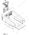
- a preferred, but absolutely not limiting, embodiment of the automated fork system 1 of the present invention is shown and described.
- Such system is equipped with a fork-carrier plate 9 and has two parallel and extensible shaped arms 7.
- the two parallel arms 7 can be moved in a lateral direction by means of, for example, hydraulic actuators arranged in the fork-carrier plate 9, to alter the horizontal distance between the two arms 7 in order to embrace pallet 8 having different widths, by engaging the recess available below the pallet 8 with a different size.
- respective fork arms 3 are arranged under the respective arms 7.
- the fork arms 3 can be moved along the arms 7, meaning the fork arms 3 can be moved away or towards the fork-carrier plate 9, to accommodate for long and short pallets 8.
- the pallet 8 is typically loaded with a stack of packages or other items to be transported, although this is not illustrated in Fig. 1 for clarity of illustration.
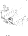
- FIG. 1A in which the pallet itself is not shown for clarity of illustration, shows the arms 7 and fork arms 3 having some of the prongs 5 extend out from the fork arms 3 and into such spaces of the pallet, while other prongs remain retracted, because their positions are in register with feet of the pallet.
- each of the two fork arms 3 has quite a number of integral or independent retractable prongs 5:
- Each fork arm 3 typically has five or more prongs 5, more preferably ten or more prongs 5, and most preferably from twelve to twenty prongs 5.
- fifteen prongs 5 for each fork arm 3, drawn in their maximum extension position, are shown in this specific case.
- Number, structural strength and extension stroke of the prongs 5, mutually equal or different, are variable and will be adapted to a specific coupling need with the types of pallets 8 to be lifted.
- Each fork arm 3 contains electric, magnetic, pneumatic or hydraulic devices in order to perform the autonomous, simultaneous or coordinate movement of the prongs 5 by which the prongs 5 that are located in register with a space 11 extends into such a space 11, while prongs 5 that are in register with a foot 10 is stopped in its movement.
- a number of prongs 5 will find a respective space 11 and extend into such space 11, and those prongs 5 will be the ones that enable the arms 7 to lift the pallet 8 from the ground.
- the extension of the prongs 5 can be obtained, for example, by pneumatic actuators which could drive a single prong 5 or a group of prongs 5.
- Suitable rollers 6 and sliding plates 12 ensure the desired stroke for the prong 5; for such purpose, every prong 5 is placed on a sliding plate 12 adapted to alternatively slide through rollers 6 with which it is equipped.
- every prong 5 on the tip 5' can comprise a cutter, preferably a heated cutter, if the prong 5 itself has to open its way by penetrating a coating film which overhangs on the pallet 8 preventing the respective space 11 from being engaged.
- the extension force of every single prong 5 is regulated to win frictions and penetrate possible plastic film coatings, without however damaging the pallet 8 should the prong stroke be prevented by the abutment on structural elements, such as a foot 10, of the pallet 8 itself.
- the pneumatic actuator 4 may be provided with a pressure regulator 13, such that the prong 5 cannot push with a too high force if a foot 10 is in its way of movement.
- Other types of sensors are also possible, such sensors using mechanical, hydraulic, pneumatic or optical sensing principles to detect if the prong 5 is extended against a foot 10, or another structural element of the pallet 8, and that therefore the further extension of the prong 5 should be stopped.
- Electric, pneumatic, hydraulic, magnetic or optical sensors monitor the actual stroke of every single prong 5, so that an operator or the controlling computer can decide whether an enough and correctly distributed number of prongs 5 has embraced the pallet 8, by extending into spaces 11, on both fork arms 3 and therefore it is safe to proceed with a lifting of the pallet 8.
- Lifting of the pallet 8 occurs after the due fork arms 3 have been closed to the width of the pallet 8 to be transported and after that the number and distribution of the engaged prongs 5, meaning prongs extending into spaces 11, has been judged enough for lifting the pallet 8 and any load placed thereon.
- Each of the extensible shaped arms 7 can be equipped with standard assembling connections 2 on commercial fork-carrier plates, namely fork-carrier plates already present on the market to use standard lifting accessories, or can be directly assembled on a new and different fork-carrier plate suitably obtained for this exclusive use.
- FIG. 6 illustrates an automated guided vehicle 14.
- the automated guided vehicle or automatic guided vehicle is a portable robot that may be guided by, e.g., lines or wires on the floor, or by radio waves, vision cameras, magnets, laser etc. for navigation.
- the automated guided vehicle 14 is provided with the automated fork system 1 described hereinabove.
- the automated fork system 1 may be attached by means of the standard assembling connections 2.
- the automated guided vehicle 14 can automatically pick up a pallet 8, wherein the prongs 5 of the fork arms 3 of the automated fork system 1 automatically can find and extend into spaces 11, and avoid damaging feet 10, such that the automated guided vehicle 14 can automatically and safely lift and then transport the pallet 8 from one location to another.
- the invention further deals with a method for automatically lifting a pallet, this method comprising the steps of:
Landscapes
- Engineering & Computer Science (AREA)
- Transportation (AREA)
- Structural Engineering (AREA)
- Civil Engineering (AREA)
- Life Sciences & Earth Sciences (AREA)
- Geology (AREA)
- Mechanical Engineering (AREA)
- Forklifts And Lifting Vehicles (AREA)
- Warehouses Or Storage Devices (AREA)
Claims (12)
- Automatisiertes Gabelsystem (1) umfassend:- mindestens zwei Arme (7);- mindestens eine Gabelstützplatte (9), die mit den Armen (7) verbunden ist;- mindestens zwei Gabelarme (3), die jeweils mit einem Arm (7) verbunden sind;- mehrere einziehbare Zinken (5), die mit mindestens einem Gabelarm (3) verbunden sind, wobei die beiden Gabelarme (3) unter ihren jeweiligen Armen (7) angeordnet sind,dadurch gekennzeichnet, dass:- die beiden Arme (7) über Mittel zur Bewegung der Arme in seitlicher Richtung in seitlicher Richtung beweglich sind, um den horizontalen Abstand zwischen den beiden Armen (7) zu verändern, um Paletten (8) unterschiedlicher Breite zu erfassen , und- die beiden Gabelarme (3) sind so gestaltet, dass sie sich entlang der Arme (7) vom Gabelträger (9) weg oder hin dazu bewegen können, um lange und kurze Paletten (8) aufzunehmen.
- Automatisiertes Gabelsystem (1) nach dem vorherigen Anspruch, dadurch gekennzeichnet, dass jeder der mindestens zwei Gabelarme (3) mehrere Zinken (5) umfasst, wobei vorzugsweise jeder Gabelarm (3) elektrische, magnetische Vorrichtungen enthält, pneumatisch oder hydraulisch, um eine autonome, gleichzeitige oder koordinierte Bewegung der Zinken (5) zu realisieren.
- Automatisiertes Gabelsystem (1) nach Anspruch 1 oder 2, dadurch gekennzeichnet, dass ein Ausfahren der Zinken (5) über pneumatische Aktoren (4) erfolgt, die einen einzelnen Zinken (5) oder eine Gruppe dieser Zinken (5) steuern.
- Automatisiertes Gabelsystem (1) nach Anspruch 1, 2 oder 3, dadurch gekennzeichnet, dass jeder Zinken (5) auf einer Gleitplatte (12) platziert ist und durch Rollen (6) gleiten kann, von denen die Gleitplatte (12) ausgestattet ist.
- Automatisiertes Gabelsystem (1) nach einem der vorhergehenden Ansprüche, dadurch gekennzeichnet, dass zumindest einige der Zinken (5) an ihrer jeweiligen Spitze (5') eine Schneidkante, vorzugsweise eine beheizte Schneidkante, aufweisen der Fall, in dem jeder Zinken (5) seinen Weg durch eine an der Palette (8) hängende Abdeckfolie durchdringen muss, die den Eingriff eines Lichts (11) durch den Zinken (5) verhindert.
- Automatisiertes Gabelsystem (1) nach einem der vorhergehenden Ansprüche, dadurch gekennzeichnet, dass die Zinken (5) so ausgelegt sind, dass sie sich beim Auftreffen auf ein Hindernis (10) nicht weiter ausfahren und innerhalb der Gabelarme (3) verbleiben.
- Automatisiertes Gabelsystem (1) nach Anspruch 6, wobei mindestens einige der Zinken (5) mit einzelnen Sensoren ausgestattet sind, die so angeordnet sind, dass sie erkennen, wann sich die Zinke (5) auf ein Hindernis (10) zubewegt, vorzugsweise mit dem Sensor des wobei die Zinken (5) so angeordnet sind, dass sie zwischen undurchdringlichen Hindernissen, beispielsweise den Füßen (10) einer Palette (8), und durchdringbaren Hindernissen, beispielsweise der Abdeckfolie einer Palette (8), unterscheiden.
- Automatisiertes Gabelsystem (1) nach einem der vorhergehenden Ansprüche, dadurch gekennzeichnet, dass es zusätzlich mit elektrischen, pneumatischen, hydraulischen, magnetischen oder optischen Sensoren ausgestattet ist, die den tatsächlichen Hub jedes einzelnen Zinkens (5) überwachen.
- Automatisiertes Gabelsystem (1) nach einem der vorhergehenden Ansprüche, dadurch gekennzeichnet, dass die einziehbaren Zinken (5), integriert oder unabhängig, mindestens gleich fünf für jeden Gabelarm (3), noch bevorzugter mindestens zehn pro sind pro Gabelarm (3) und am besten zwölf bis zwanzig für jeden Gabelarm (3).
- Automatisiertes Gabelsystem (1) nach einem der vorhergehenden Ansprüche, dadurch gekennzeichnet, dass das System ein Palettenhubgabelstaplersystem (1) ist, das zum Heben von Paletten (8) mit Füßen (10) und Lichtern (11) ausgelegt ist) zwischen den Füßen (10).
- Fahrerloses Transportfahrzeug, dadurch gekennzeichnet, dass es ein automatisiertes Gabelsystem (1) nach einem der Ansprüche 1 bis 10 umfasst.
- Verfahren zum automatischen Anheben einer Palette unter Verwendung eines automatisierten Gabelsystems (1) nach einem der Ansprüche 1 bis 10, wobei das Verfahren die folgenden Schritte umfasst:- zwei Arme (7) bewegen, um die Palette (8) zwischen sich zu umfassen,- aktivieren mindestens eines an mindestens einem der Arme (7) angeordneten Gabelarms (3), um mehrere Zinken (5) in Richtung der Palette (8) auszufahren,- diejenigen unter den Zinken (5) zu erkennen, die sich in Richtung eines Hindernisses (10) der Palette (8) erstrecken, und das Ausfahren der Zinken (5) zu stoppen,- weitere Zinken (5) in die Öffnungen (11) zwischen den Hindernissen (10) der Palette (8) einführen und- heben Sie die Arme (7) an, um die Palette (8) vom Boden anzuheben.
Priority Applications (5)
| Application Number | Priority Date | Filing Date | Title |
|---|---|---|---|
| EP19425058.5A EP3770106B1 (de) | 2019-07-25 | 2019-07-25 | Automatisiertes gabelsystem und verfahren sowie automatisiertes geführtes fahrzeug mit einem solchen gabelsystem |
| ES20731114T ES2949810T3 (es) | 2019-07-25 | 2020-06-11 | Sistema y procedimiento de horquilla automatizado y vehículo automáticamente guiado provisto de dicho sistema de horquilla |
| PCT/EP2020/066176 WO2021013430A1 (en) | 2019-07-25 | 2020-06-11 | Automated fork system and method and automated guided vehicle having such fork system |
| PL20731114.3T PL4003898T3 (pl) | 2019-07-25 | 2020-06-11 | Zautomatyzowany układ widłowy i wózek samojezdny mający taki układ widłowy |
| EP20731114.3A EP4003898B1 (de) | 2019-07-25 | 2020-06-11 | Automatisiertes gabelsystem und verfahren sowie automatisiertes geführtes fahrzeug mit einem solchen gabelsystem |
Applications Claiming Priority (1)
| Application Number | Priority Date | Filing Date | Title |
|---|---|---|---|
| EP19425058.5A EP3770106B1 (de) | 2019-07-25 | 2019-07-25 | Automatisiertes gabelsystem und verfahren sowie automatisiertes geführtes fahrzeug mit einem solchen gabelsystem |
Publications (2)
| Publication Number | Publication Date |
|---|---|
| EP3770106A1 EP3770106A1 (de) | 2021-01-27 |
| EP3770106B1 true EP3770106B1 (de) | 2024-07-31 |
Family
ID=67874409
Family Applications (2)
| Application Number | Title | Priority Date | Filing Date |
|---|---|---|---|
| EP19425058.5A Active EP3770106B1 (de) | 2019-07-25 | 2019-07-25 | Automatisiertes gabelsystem und verfahren sowie automatisiertes geführtes fahrzeug mit einem solchen gabelsystem |
| EP20731114.3A Active EP4003898B1 (de) | 2019-07-25 | 2020-06-11 | Automatisiertes gabelsystem und verfahren sowie automatisiertes geführtes fahrzeug mit einem solchen gabelsystem |
Family Applications After (1)
| Application Number | Title | Priority Date | Filing Date |
|---|---|---|---|
| EP20731114.3A Active EP4003898B1 (de) | 2019-07-25 | 2020-06-11 | Automatisiertes gabelsystem und verfahren sowie automatisiertes geführtes fahrzeug mit einem solchen gabelsystem |
Country Status (4)
| Country | Link |
|---|---|
| EP (2) | EP3770106B1 (de) |
| ES (1) | ES2949810T3 (de) |
| PL (1) | PL4003898T3 (de) |
| WO (1) | WO2021013430A1 (de) |
Families Citing this family (1)
| Publication number | Priority date | Publication date | Assignee | Title |
|---|---|---|---|---|
| KR20240165200A (ko) * | 2023-05-15 | 2024-11-22 | 엘지전자 주식회사 | 운송 로봇 |
Family Cites Families (10)
| Publication number | Priority date | Publication date | Assignee | Title |
|---|---|---|---|---|
| US3930587A (en) * | 1973-04-12 | 1976-01-06 | Bliss George N | Retractable chain lifting device |
| US4747610A (en) * | 1987-08-20 | 1988-05-31 | Barrett Industrial Trucks, Inc. | Pallet sensor for lift truck |
| DE4234375C2 (de) * | 1992-10-12 | 1995-10-12 | Noell Gmbh | Vorrichtung zur Personen- und Kollisionssicherung von fahrerlosen Gabelhubfahrzeugen |
| FR2721594A1 (fr) * | 1994-06-27 | 1995-12-29 | Christian Blonde | Dispositif de stockage pour palettes. |
| DE29620342U1 (de) * | 1996-11-22 | 1998-03-19 | Westfalia-WST-Systemtechnik GmbH & Co. KG, 33829 Borgholzhausen | Satellitenfahrzeug |
| FR2773551B1 (fr) * | 1998-01-09 | 2000-03-24 | Fleury Michon Logistique | Magasin a palettes, chariot de manutention pour palettes equipe d'un tel magasin et procede d'alimentation en palettes du chariot |
| DE102011120739A1 (de) * | 2010-12-09 | 2012-06-14 | SSI Schäfer Noell GmbH Lager- und Systemtechnik | Universelles Lastaufnahmemittel für palettenlose Handhabung von Paletten-Ladegütern |
| GB201300652D0 (en) * | 2013-01-15 | 2013-02-27 | Eccleston Simon | A pallet stacking apparatus |
| JP6239653B2 (ja) * | 2016-01-19 | 2017-11-29 | 昭和アルミニウム缶株式会社 | 切目刻設方法 |
| CN206985635U (zh) * | 2017-05-22 | 2018-02-09 | 珠海见卓思特科技有限公司 | 叉车 |
-
2019
- 2019-07-25 EP EP19425058.5A patent/EP3770106B1/de active Active
-
2020
- 2020-06-11 EP EP20731114.3A patent/EP4003898B1/de active Active
- 2020-06-11 WO PCT/EP2020/066176 patent/WO2021013430A1/en not_active Ceased
- 2020-06-11 ES ES20731114T patent/ES2949810T3/es active Active
- 2020-06-11 PL PL20731114.3T patent/PL4003898T3/pl unknown
Also Published As
| Publication number | Publication date |
|---|---|
| WO2021013430A1 (en) | 2021-01-28 |
| EP3770106A1 (de) | 2021-01-27 |
| EP4003898A1 (de) | 2022-06-01 |
| PL4003898T3 (pl) | 2023-07-24 |
| EP4003898B1 (de) | 2023-04-19 |
| ES2949810T3 (es) | 2023-10-03 |
Similar Documents
| Publication | Publication Date | Title |
|---|---|---|
| US11345577B2 (en) | Mobile automated guided vehicle pallet stacker and destacker system and method therefor | |
| EP3718951B1 (de) | Lasthandhabungsmodul für ein materialhandhabungsfahrzeug | |
| EP3681828B1 (de) | Vorrichtung und verfahren zum greifen und handhaben von paletten und zwischenlagen von palettierten ladungen sowie zugehörige verfahren | |
| EP2542496B1 (de) | Verfahren und vorrichtung zur erfassung der einrastung und der ausrastung einer objektlast durch automatisierte fahrzeuge | |
| US11795014B2 (en) | Depalletizing robots for an autonomous warehouse | |
| JP2022553259A (ja) | 視覚支援型のロボット化デパレタイザ | |
| CN110194341A (zh) | 一种搬运机器人及仓储系统 | |
| US20170183157A9 (en) | Robotic manipulator for warehouses | |
| JP2022506757A (ja) | 物体を移送するためのパレット・ピック・プット・システムの作動方法 | |
| KR102159040B1 (ko) | 승강수단이 구비된 운반 로봇 | |
| JP2022179331A (ja) | 無人フォークリフト | |
| EP4003898B1 (de) | Automatisiertes gabelsystem und verfahren sowie automatisiertes geführtes fahrzeug mit einem solchen gabelsystem | |
| US11117790B2 (en) | Industrial truck comprising a thrust device | |
| CN113247510B (zh) | 搬运装置及仓储系统 | |
| US20180229987A1 (en) | Device for Transporting a Transport Item, and Method | |
| TWI835329B (zh) | 堆棧容納結構 | |
| US20240157565A1 (en) | Robotic system transfer unit cell and method of operation thereof | |
| CN214826315U (zh) | 搬运装置及仓储系统 | |
| EP1847491A1 (de) | System und Verfahren zur Erfassung und Kontrolle von grossen Obstkisten | |
| EP4163246A1 (de) | Vorrichtung zum aufnehmen von paletten | |
| EP4613696A2 (de) | Systeme und verfahren zum andocken von automatisch geführten fahrzeugen an ein materialhandhabungsfahrzeug | |
| CN219708017U (zh) | 货物搬运系统 | |
| CN219363134U (zh) | 升降平台及其控制系统 | |
| HK40037444A (en) | Load handling module for a material handling vehicle | |
| WO2026019491A1 (en) | Lift attachment for transporting server racks |
Legal Events
| Date | Code | Title | Description |
|---|---|---|---|
| PUAI | Public reference made under article 153(3) epc to a published international application that has entered the european phase |
Free format text: ORIGINAL CODE: 0009012 |
|
| STAA | Information on the status of an ep patent application or granted ep patent |
Free format text: STATUS: THE APPLICATION HAS BEEN PUBLISHED |
|
| AK | Designated contracting states |
Kind code of ref document: A1 Designated state(s): AL AT BE BG CH CY CZ DE DK EE ES FI FR GB GR HR HU IE IS IT LI LT LU LV MC MK MT NL NO PL PT RO RS SE SI SK SM TR |
|
| AX | Request for extension of the european patent |
Extension state: BA ME |
|
| STAA | Information on the status of an ep patent application or granted ep patent |
Free format text: STATUS: REQUEST FOR EXAMINATION WAS MADE |
|
| 17P | Request for examination filed |
Effective date: 20210630 |
|
| RBV | Designated contracting states (corrected) |
Designated state(s): AL AT BE BG CH CY CZ DE DK EE ES FI FR GB GR HR HU IE IS IT LI LT LU LV MC MK MT NL NO PL PT RO RS SE SI SK SM TR |
|
| STAA | Information on the status of an ep patent application or granted ep patent |
Free format text: STATUS: EXAMINATION IS IN PROGRESS |
|
| 17Q | First examination report despatched |
Effective date: 20221007 |
|
| GRAP | Despatch of communication of intention to grant a patent |
Free format text: ORIGINAL CODE: EPIDOSNIGR1 |
|
| STAA | Information on the status of an ep patent application or granted ep patent |
Free format text: STATUS: GRANT OF PATENT IS INTENDED |
|
| INTG | Intention to grant announced |
Effective date: 20240305 |
|
| GRAS | Grant fee paid |
Free format text: ORIGINAL CODE: EPIDOSNIGR3 |
|
| GRAA | (expected) grant |
Free format text: ORIGINAL CODE: 0009210 |
|
| STAA | Information on the status of an ep patent application or granted ep patent |
Free format text: STATUS: THE PATENT HAS BEEN GRANTED |
|
| AK | Designated contracting states |
Kind code of ref document: B1 Designated state(s): AL AT BE BG CH CY CZ DE DK EE ES FI FR GB GR HR HU IE IS IT LI LT LU LV MC MK MT NL NO PL PT RO RS SE SI SK SM TR |
|
| REG | Reference to a national code |
Ref country code: CH Ref legal event code: EP Ref country code: GB Ref legal event code: FG4D |
|
| REG | Reference to a national code |
Ref country code: DE Ref legal event code: R096 Ref document number: 602019056054 Country of ref document: DE |
|
| REG | Reference to a national code |
Ref country code: IE Ref legal event code: FG4D |
|
| REG | Reference to a national code |
Ref country code: LT Ref legal event code: MG9D |
|
| REG | Reference to a national code |
Ref country code: NL Ref legal event code: MP Effective date: 20240731 |
|
| PG25 | Lapsed in a contracting state [announced via postgrant information from national office to epo] |
Ref country code: PT Free format text: LAPSE BECAUSE OF FAILURE TO SUBMIT A TRANSLATION OF THE DESCRIPTION OR TO PAY THE FEE WITHIN THE PRESCRIBED TIME-LIMIT Effective date: 20241202 |
|
| REG | Reference to a national code |
Ref country code: AT Ref legal event code: MK05 Ref document number: 1708322 Country of ref document: AT Kind code of ref document: T Effective date: 20240731 |
|
| PG25 | Lapsed in a contracting state [announced via postgrant information from national office to epo] |
Ref country code: PT Free format text: LAPSE BECAUSE OF FAILURE TO SUBMIT A TRANSLATION OF THE DESCRIPTION OR TO PAY THE FEE WITHIN THE PRESCRIBED TIME-LIMIT Effective date: 20241202 |
|
| PG25 | Lapsed in a contracting state [announced via postgrant information from national office to epo] |
Ref country code: NO Free format text: LAPSE BECAUSE OF FAILURE TO SUBMIT A TRANSLATION OF THE DESCRIPTION OR TO PAY THE FEE WITHIN THE PRESCRIBED TIME-LIMIT Effective date: 20241031 |
|
| PG25 | Lapsed in a contracting state [announced via postgrant information from national office to epo] |
Ref country code: NL Free format text: LAPSE BECAUSE OF FAILURE TO SUBMIT A TRANSLATION OF THE DESCRIPTION OR TO PAY THE FEE WITHIN THE PRESCRIBED TIME-LIMIT Effective date: 20240731 Ref country code: FI Free format text: LAPSE BECAUSE OF FAILURE TO SUBMIT A TRANSLATION OF THE DESCRIPTION OR TO PAY THE FEE WITHIN THE PRESCRIBED TIME-LIMIT Effective date: 20240731 Ref country code: PL Free format text: LAPSE BECAUSE OF FAILURE TO SUBMIT A TRANSLATION OF THE DESCRIPTION OR TO PAY THE FEE WITHIN THE PRESCRIBED TIME-LIMIT Effective date: 20240731 Ref country code: GR Free format text: LAPSE BECAUSE OF FAILURE TO SUBMIT A TRANSLATION OF THE DESCRIPTION OR TO PAY THE FEE WITHIN THE PRESCRIBED TIME-LIMIT Effective date: 20241101 |
|
| PG25 | Lapsed in a contracting state [announced via postgrant information from national office to epo] |
Ref country code: BG Free format text: LAPSE BECAUSE OF FAILURE TO SUBMIT A TRANSLATION OF THE DESCRIPTION OR TO PAY THE FEE WITHIN THE PRESCRIBED TIME-LIMIT Effective date: 20240731 |
|
| PG25 | Lapsed in a contracting state [announced via postgrant information from national office to epo] |
Ref country code: LV Free format text: LAPSE BECAUSE OF FAILURE TO SUBMIT A TRANSLATION OF THE DESCRIPTION OR TO PAY THE FEE WITHIN THE PRESCRIBED TIME-LIMIT Effective date: 20240731 |
|
| PG25 | Lapsed in a contracting state [announced via postgrant information from national office to epo] |
Ref country code: IS Free format text: LAPSE BECAUSE OF FAILURE TO SUBMIT A TRANSLATION OF THE DESCRIPTION OR TO PAY THE FEE WITHIN THE PRESCRIBED TIME-LIMIT Effective date: 20241130 Ref country code: AT Free format text: LAPSE BECAUSE OF FAILURE TO SUBMIT A TRANSLATION OF THE DESCRIPTION OR TO PAY THE FEE WITHIN THE PRESCRIBED TIME-LIMIT Effective date: 20240731 |
|
| PG25 | Lapsed in a contracting state [announced via postgrant information from national office to epo] |
Ref country code: HR Free format text: LAPSE BECAUSE OF FAILURE TO SUBMIT A TRANSLATION OF THE DESCRIPTION OR TO PAY THE FEE WITHIN THE PRESCRIBED TIME-LIMIT Effective date: 20240731 |
|
| PG25 | Lapsed in a contracting state [announced via postgrant information from national office to epo] |
Ref country code: ES Free format text: LAPSE BECAUSE OF FAILURE TO SUBMIT A TRANSLATION OF THE DESCRIPTION OR TO PAY THE FEE WITHIN THE PRESCRIBED TIME-LIMIT Effective date: 20240731 Ref country code: RS Free format text: LAPSE BECAUSE OF FAILURE TO SUBMIT A TRANSLATION OF THE DESCRIPTION OR TO PAY THE FEE WITHIN THE PRESCRIBED TIME-LIMIT Effective date: 20241031 |
|
| PG25 | Lapsed in a contracting state [announced via postgrant information from national office to epo] |
Ref country code: RS Free format text: LAPSE BECAUSE OF FAILURE TO SUBMIT A TRANSLATION OF THE DESCRIPTION OR TO PAY THE FEE WITHIN THE PRESCRIBED TIME-LIMIT Effective date: 20241031 Ref country code: PL Free format text: LAPSE BECAUSE OF FAILURE TO SUBMIT A TRANSLATION OF THE DESCRIPTION OR TO PAY THE FEE WITHIN THE PRESCRIBED TIME-LIMIT Effective date: 20240731 Ref country code: NO Free format text: LAPSE BECAUSE OF FAILURE TO SUBMIT A TRANSLATION OF THE DESCRIPTION OR TO PAY THE FEE WITHIN THE PRESCRIBED TIME-LIMIT Effective date: 20241031 Ref country code: NL Free format text: LAPSE BECAUSE OF FAILURE TO SUBMIT A TRANSLATION OF THE DESCRIPTION OR TO PAY THE FEE WITHIN THE PRESCRIBED TIME-LIMIT Effective date: 20240731 Ref country code: LV Free format text: LAPSE BECAUSE OF FAILURE TO SUBMIT A TRANSLATION OF THE DESCRIPTION OR TO PAY THE FEE WITHIN THE PRESCRIBED TIME-LIMIT Effective date: 20240731 Ref country code: IS Free format text: LAPSE BECAUSE OF FAILURE TO SUBMIT A TRANSLATION OF THE DESCRIPTION OR TO PAY THE FEE WITHIN THE PRESCRIBED TIME-LIMIT Effective date: 20241130 Ref country code: HR Free format text: LAPSE BECAUSE OF FAILURE TO SUBMIT A TRANSLATION OF THE DESCRIPTION OR TO PAY THE FEE WITHIN THE PRESCRIBED TIME-LIMIT Effective date: 20240731 Ref country code: GR Free format text: LAPSE BECAUSE OF FAILURE TO SUBMIT A TRANSLATION OF THE DESCRIPTION OR TO PAY THE FEE WITHIN THE PRESCRIBED TIME-LIMIT Effective date: 20241101 Ref country code: FI Free format text: LAPSE BECAUSE OF FAILURE TO SUBMIT A TRANSLATION OF THE DESCRIPTION OR TO PAY THE FEE WITHIN THE PRESCRIBED TIME-LIMIT Effective date: 20240731 Ref country code: ES Free format text: LAPSE BECAUSE OF FAILURE TO SUBMIT A TRANSLATION OF THE DESCRIPTION OR TO PAY THE FEE WITHIN THE PRESCRIBED TIME-LIMIT Effective date: 20240731 Ref country code: BG Free format text: LAPSE BECAUSE OF FAILURE TO SUBMIT A TRANSLATION OF THE DESCRIPTION OR TO PAY THE FEE WITHIN THE PRESCRIBED TIME-LIMIT Effective date: 20240731 Ref country code: AT Free format text: LAPSE BECAUSE OF FAILURE TO SUBMIT A TRANSLATION OF THE DESCRIPTION OR TO PAY THE FEE WITHIN THE PRESCRIBED TIME-LIMIT Effective date: 20240731 |
|
| PG25 | Lapsed in a contracting state [announced via postgrant information from national office to epo] |
Ref country code: SM Free format text: LAPSE BECAUSE OF FAILURE TO SUBMIT A TRANSLATION OF THE DESCRIPTION OR TO PAY THE FEE WITHIN THE PRESCRIBED TIME-LIMIT Effective date: 20240731 Ref country code: RO Free format text: LAPSE BECAUSE OF FAILURE TO SUBMIT A TRANSLATION OF THE DESCRIPTION OR TO PAY THE FEE WITHIN THE PRESCRIBED TIME-LIMIT Effective date: 20240731 Ref country code: DK Free format text: LAPSE BECAUSE OF FAILURE TO SUBMIT A TRANSLATION OF THE DESCRIPTION OR TO PAY THE FEE WITHIN THE PRESCRIBED TIME-LIMIT Effective date: 20240731 |
|
| PG25 | Lapsed in a contracting state [announced via postgrant information from national office to epo] |
Ref country code: EE Free format text: LAPSE BECAUSE OF FAILURE TO SUBMIT A TRANSLATION OF THE DESCRIPTION OR TO PAY THE FEE WITHIN THE PRESCRIBED TIME-LIMIT Effective date: 20240731 |
|
| PG25 | Lapsed in a contracting state [announced via postgrant information from national office to epo] |
Ref country code: CZ Free format text: LAPSE BECAUSE OF FAILURE TO SUBMIT A TRANSLATION OF THE DESCRIPTION OR TO PAY THE FEE WITHIN THE PRESCRIBED TIME-LIMIT Effective date: 20240731 |
|
| PG25 | Lapsed in a contracting state [announced via postgrant information from national office to epo] |
Ref country code: IT Free format text: LAPSE BECAUSE OF FAILURE TO SUBMIT A TRANSLATION OF THE DESCRIPTION OR TO PAY THE FEE WITHIN THE PRESCRIBED TIME-LIMIT Effective date: 20240731 Ref country code: SK Free format text: LAPSE BECAUSE OF FAILURE TO SUBMIT A TRANSLATION OF THE DESCRIPTION OR TO PAY THE FEE WITHIN THE PRESCRIBED TIME-LIMIT Effective date: 20240731 |
|
| REG | Reference to a national code |
Ref country code: DE Ref legal event code: R097 Ref document number: 602019056054 Country of ref document: DE |
|
| PLBE | No opposition filed within time limit |
Free format text: ORIGINAL CODE: 0009261 |
|
| STAA | Information on the status of an ep patent application or granted ep patent |
Free format text: STATUS: NO OPPOSITION FILED WITHIN TIME LIMIT |
|
| 26N | No opposition filed |
Effective date: 20250501 |
|
| PG25 | Lapsed in a contracting state [announced via postgrant information from national office to epo] |
Ref country code: SE Free format text: LAPSE BECAUSE OF FAILURE TO SUBMIT A TRANSLATION OF THE DESCRIPTION OR TO PAY THE FEE WITHIN THE PRESCRIBED TIME-LIMIT Effective date: 20240731 |