EP3770004A1 - Mit einem reflektorelement ausgestattete beleuchtungsvorrichtung - Google Patents
Mit einem reflektorelement ausgestattete beleuchtungsvorrichtung Download PDFInfo
- Publication number
- EP3770004A1 EP3770004A1 EP20186759.5A EP20186759A EP3770004A1 EP 3770004 A1 EP3770004 A1 EP 3770004A1 EP 20186759 A EP20186759 A EP 20186759A EP 3770004 A1 EP3770004 A1 EP 3770004A1
- Authority
- EP
- European Patent Office
- Prior art keywords
- channel
- support body
- lighting
- reflector element
- lighting device
- Prior art date
- Legal status (The legal status is an assumption and is not a legal conclusion. Google has not performed a legal analysis and makes no representation as to the accuracy of the status listed.)
- Granted
Links
Images


Classifications
-
- F—MECHANICAL ENGINEERING; LIGHTING; HEATING; WEAPONS; BLASTING
- F21—LIGHTING
- F21V—FUNCTIONAL FEATURES OR DETAILS OF LIGHTING DEVICES OR SYSTEMS THEREOF; STRUCTURAL COMBINATIONS OF LIGHTING DEVICES WITH OTHER ARTICLES, NOT OTHERWISE PROVIDED FOR
- F21V19/00—Fastening of light sources or lamp holders
- F21V19/001—Fastening of light sources or lamp holders the light sources being semiconductors devices, e.g. LEDs
- F21V19/003—Fastening of light source holders, e.g. of circuit boards or substrates holding light sources
- F21V19/0045—Fastening of light source holders, e.g. of circuit boards or substrates holding light sources by tongue and groove connections, e.g. dovetail interlocking means fixed by sliding
-
- B—PERFORMING OPERATIONS; TRANSPORTING
- B60—VEHICLES IN GENERAL
- B60K—ARRANGEMENT OR MOUNTING OF PROPULSION UNITS OR OF TRANSMISSIONS IN VEHICLES; ARRANGEMENT OR MOUNTING OF PLURAL DIVERSE PRIME-MOVERS IN VEHICLES; AUXILIARY DRIVES FOR VEHICLES; INSTRUMENTATION OR DASHBOARDS FOR VEHICLES; ARRANGEMENTS IN CONNECTION WITH COOLING, AIR INTAKE, GAS EXHAUST OR FUEL SUPPLY OF PROPULSION UNITS IN VEHICLES
- B60K35/00—Instruments specially adapted for vehicles; Arrangement of instruments in or on vehicles
- B60K35/20—Output arrangements, i.e. from vehicle to user, associated with vehicle functions or specially adapted therefor
-
- B—PERFORMING OPERATIONS; TRANSPORTING
- B60—VEHICLES IN GENERAL
- B60L—PROPULSION OF ELECTRICALLY-PROPELLED VEHICLES; SUPPLYING ELECTRIC POWER FOR AUXILIARY EQUIPMENT OF ELECTRICALLY-PROPELLED VEHICLES; ELECTRODYNAMIC BRAKE SYSTEMS FOR VEHICLES IN GENERAL; MAGNETIC SUSPENSION OR LEVITATION FOR VEHICLES; MONITORING OPERATING VARIABLES OF ELECTRICALLY-PROPELLED VEHICLES; ELECTRIC SAFETY DEVICES FOR ELECTRICALLY-PROPELLED VEHICLES
- B60L50/00—Electric propulsion with power supplied within the vehicle
- B60L50/50—Electric propulsion with power supplied within the vehicle using propulsion power supplied by batteries or fuel cells
- B60L50/60—Electric propulsion with power supplied within the vehicle using propulsion power supplied by batteries or fuel cells using power supplied by batteries
- B60L50/64—Constructional details of batteries specially adapted for electric vehicles
-
- B—PERFORMING OPERATIONS; TRANSPORTING
- B60—VEHICLES IN GENERAL
- B60L—PROPULSION OF ELECTRICALLY-PROPELLED VEHICLES; SUPPLYING ELECTRIC POWER FOR AUXILIARY EQUIPMENT OF ELECTRICALLY-PROPELLED VEHICLES; ELECTRODYNAMIC BRAKE SYSTEMS FOR VEHICLES IN GENERAL; MAGNETIC SUSPENSION OR LEVITATION FOR VEHICLES; MONITORING OPERATING VARIABLES OF ELECTRICALLY-PROPELLED VEHICLES; ELECTRIC SAFETY DEVICES FOR ELECTRICALLY-PROPELLED VEHICLES
- B60L58/00—Methods or circuit arrangements for monitoring or controlling batteries or fuel cells, specially adapted for electric vehicles
- B60L58/10—Methods or circuit arrangements for monitoring or controlling batteries or fuel cells, specially adapted for electric vehicles for monitoring or controlling batteries
- B60L58/12—Methods or circuit arrangements for monitoring or controlling batteries or fuel cells, specially adapted for electric vehicles for monitoring or controlling batteries responding to state of charge [SoC]
-
- F—MECHANICAL ENGINEERING; LIGHTING; HEATING; WEAPONS; BLASTING
- F21—LIGHTING
- F21V—FUNCTIONAL FEATURES OR DETAILS OF LIGHTING DEVICES OR SYSTEMS THEREOF; STRUCTURAL COMBINATIONS OF LIGHTING DEVICES WITH OTHER ARTICLES, NOT OTHERWISE PROVIDED FOR
- F21V17/00—Fastening of component parts of lighting devices, e.g. shades, globes, refractors, reflectors, filters, screens, grids or protective cages
- F21V17/10—Fastening of component parts of lighting devices, e.g. shades, globes, refractors, reflectors, filters, screens, grids or protective cages characterised by specific fastening means or way of fastening
- F21V17/104—Fastening of component parts of lighting devices, e.g. shades, globes, refractors, reflectors, filters, screens, grids or protective cages characterised by specific fastening means or way of fastening using feather joints, e.g. tongues and grooves, with or without friction
-
- F—MECHANICAL ENGINEERING; LIGHTING; HEATING; WEAPONS; BLASTING
- F21—LIGHTING
- F21V—FUNCTIONAL FEATURES OR DETAILS OF LIGHTING DEVICES OR SYSTEMS THEREOF; STRUCTURAL COMBINATIONS OF LIGHTING DEVICES WITH OTHER ARTICLES, NOT OTHERWISE PROVIDED FOR
- F21V23/00—Arrangement of electric circuit elements in or on lighting devices
- F21V23/06—Arrangement of electric circuit elements in or on lighting devices the elements being coupling devices, e.g. connectors
-
- F—MECHANICAL ENGINEERING; LIGHTING; HEATING; WEAPONS; BLASTING
- F21—LIGHTING
- F21V—FUNCTIONAL FEATURES OR DETAILS OF LIGHTING DEVICES OR SYSTEMS THEREOF; STRUCTURAL COMBINATIONS OF LIGHTING DEVICES WITH OTHER ARTICLES, NOT OTHERWISE PROVIDED FOR
- F21V7/00—Reflectors for light sources
- F21V7/04—Optical design
-
- H—ELECTRICITY
- H02—GENERATION; CONVERSION OR DISTRIBUTION OF ELECTRIC POWER
- H02J—ELECTRIC POWER NETWORKS; CIRCUIT ARRANGEMENTS OR SYSTEMS FOR SUPPLYING OR DISTRIBUTING ELECTRIC POWER; SYSTEMS FOR STORING ELECTRIC ENERGY
- H02J7/00—Circuit arrangements for charging or discharging batteries or for supplying loads from batteries
- H02J7/80—Circuit arrangements for charging or discharging batteries or for supplying loads from batteries including monitoring or indicating arrangements
-
- B—PERFORMING OPERATIONS; TRANSPORTING
- B60—VEHICLES IN GENERAL
- B60K—ARRANGEMENT OR MOUNTING OF PROPULSION UNITS OR OF TRANSMISSIONS IN VEHICLES; ARRANGEMENT OR MOUNTING OF PLURAL DIVERSE PRIME-MOVERS IN VEHICLES; AUXILIARY DRIVES FOR VEHICLES; INSTRUMENTATION OR DASHBOARDS FOR VEHICLES; ARRANGEMENTS IN CONNECTION WITH COOLING, AIR INTAKE, GAS EXHAUST OR FUEL SUPPLY OF PROPULSION UNITS IN VEHICLES
- B60K2360/00—Indexing scheme associated with groups B60K35/00 or B60K37/00 relating to details of instruments or dashboards
- B60K2360/16—Type of output information
- B60K2360/169—Remaining operating distance or charge
-
- B—PERFORMING OPERATIONS; TRANSPORTING
- B60—VEHICLES IN GENERAL
- B60K—ARRANGEMENT OR MOUNTING OF PROPULSION UNITS OR OF TRANSMISSIONS IN VEHICLES; ARRANGEMENT OR MOUNTING OF PLURAL DIVERSE PRIME-MOVERS IN VEHICLES; AUXILIARY DRIVES FOR VEHICLES; INSTRUMENTATION OR DASHBOARDS FOR VEHICLES; ARRANGEMENTS IN CONNECTION WITH COOLING, AIR INTAKE, GAS EXHAUST OR FUEL SUPPLY OF PROPULSION UNITS IN VEHICLES
- B60K2360/00—Indexing scheme associated with groups B60K35/00 or B60K37/00 relating to details of instruments or dashboards
- B60K2360/20—Optical features of instruments
- B60K2360/33—Illumination features
-
- B—PERFORMING OPERATIONS; TRANSPORTING
- B60—VEHICLES IN GENERAL
- B60K—ARRANGEMENT OR MOUNTING OF PROPULSION UNITS OR OF TRANSMISSIONS IN VEHICLES; ARRANGEMENT OR MOUNTING OF PLURAL DIVERSE PRIME-MOVERS IN VEHICLES; AUXILIARY DRIVES FOR VEHICLES; INSTRUMENTATION OR DASHBOARDS FOR VEHICLES; ARRANGEMENTS IN CONNECTION WITH COOLING, AIR INTAKE, GAS EXHAUST OR FUEL SUPPLY OF PROPULSION UNITS IN VEHICLES
- B60K35/00—Instruments specially adapted for vehicles; Arrangement of instruments in or on vehicles
- B60K35/10—Input arrangements, i.e. from user to vehicle, associated with vehicle functions or specially adapted therefor
-
- B—PERFORMING OPERATIONS; TRANSPORTING
- B60—VEHICLES IN GENERAL
- B60K—ARRANGEMENT OR MOUNTING OF PROPULSION UNITS OR OF TRANSMISSIONS IN VEHICLES; ARRANGEMENT OR MOUNTING OF PLURAL DIVERSE PRIME-MOVERS IN VEHICLES; AUXILIARY DRIVES FOR VEHICLES; INSTRUMENTATION OR DASHBOARDS FOR VEHICLES; ARRANGEMENTS IN CONNECTION WITH COOLING, AIR INTAKE, GAS EXHAUST OR FUEL SUPPLY OF PROPULSION UNITS IN VEHICLES
- B60K35/00—Instruments specially adapted for vehicles; Arrangement of instruments in or on vehicles
- B60K35/20—Output arrangements, i.e. from vehicle to user, associated with vehicle functions or specially adapted therefor
- B60K35/28—Output arrangements, i.e. from vehicle to user, associated with vehicle functions or specially adapted therefor characterised by the type of the output information, e.g. video entertainment or vehicle dynamics information; characterised by the purpose of the output information, e.g. for attracting the attention of the driver
-
- F—MECHANICAL ENGINEERING; LIGHTING; HEATING; WEAPONS; BLASTING
- F21—LIGHTING
- F21V—FUNCTIONAL FEATURES OR DETAILS OF LIGHTING DEVICES OR SYSTEMS THEREOF; STRUCTURAL COMBINATIONS OF LIGHTING DEVICES WITH OTHER ARTICLES, NOT OTHERWISE PROVIDED FOR
- F21V23/00—Arrangement of electric circuit elements in or on lighting devices
- F21V23/04—Arrangement of electric circuit elements in or on lighting devices the elements being switches
-
- F—MECHANICAL ENGINEERING; LIGHTING; HEATING; WEAPONS; BLASTING
- F21—LIGHTING
- F21Y—INDEXING SCHEME ASSOCIATED WITH SUBCLASSES F21K, F21L, F21S and F21V, RELATING TO THE FORM OR THE KIND OF THE LIGHT SOURCES OR OF THE COLOUR OF THE LIGHT EMITTED
- F21Y2115/00—Light-generating elements of semiconductor light sources
- F21Y2115/10—Light-emitting diodes [LED]
-
- Y—GENERAL TAGGING OF NEW TECHNOLOGICAL DEVELOPMENTS; GENERAL TAGGING OF CROSS-SECTIONAL TECHNOLOGIES SPANNING OVER SEVERAL SECTIONS OF THE IPC; TECHNICAL SUBJECTS COVERED BY FORMER USPC CROSS-REFERENCE ART COLLECTIONS [XRACs] AND DIGESTS
- Y02—TECHNOLOGIES OR APPLICATIONS FOR MITIGATION OR ADAPTATION AGAINST CLIMATE CHANGE
- Y02T—CLIMATE CHANGE MITIGATION TECHNOLOGIES RELATED TO TRANSPORTATION
- Y02T10/00—Road transport of goods or passengers
- Y02T10/60—Other road transportation technologies with climate change mitigation effect
- Y02T10/70—Energy storage systems for electromobility, e.g. batteries
Definitions
- the present invention relates to a lighting device using electrically powered lighting sources, in particular solid-state lighting sources such as LED sources.
- One or more embodiments may be applied to implement a device for indicating a charge state of a battery pack mounted on board a motor vehicle powered by an electric motor.
- PCB printed circuit board
- the present invention is based on the desire to overcome some drawbacks resulting from the use of a lighting device having a configuration as stated above of the lighting sources.
- a first object of the present invention is to implement a lighting device, using electrically powered lighting sources, which makes it possible to direct effectively and to improve the homogeneity of the light radiation emitted from the lighting sources.
- a further object of the present invention is to implement a lighting device which has as a whole a structure which is simple in construction, compact and low in bulk, and which has low production costs.
- a final but no less important object of the present invention is to implement a lighting device which provides light indicators which are easily observable by a user.
- the present invention relates to a lighting device using electrically powered lighting sources, in particular solid-state lighting sources such as LED sources, comprising:
- the lighting device according to the present invention has a structure which is simple in construction and extremely compact, without thereby becoming less effective in directing and distributing the light rays emitted from the light sources onto the corresponding lenses.
- the reflector element is formed in a single piece of plastics material and is white in colour in order to maximise the effectiveness of its reflective properties.
- the lighting sources are solid-state lighting sources, such as LED sources which emit coloured light.
- the reflector element has a principal plane of reflection carrying said plurality of reflective surfaces which, in the mounted state, is directed perpendicular to the principal plane of the printed circuit board and to the principal direction of the channel-shaped portions, so as to cover the first ends of the channel-shaped portions.
- each channel-shaped portion has an internal surface covered with transparent polycarbonate.
- the reflective surfaces of the reflector element are separated along the principal plane by a plurality of partition walls, in such a way that, in the assembled state of the reflector element on the second support body, the partition walls come into abutment against corresponding dividing walls of each channel-shaped portion, in such a way that the light emitted from a single lighting source arranged within one of the channel-shaped portions does not interfere with the light emitted by another lighting source arranged within an adjacent channel-shaped portion.
- the reflective surfaces are separated along the principal plane of reflection by corresponding vertical recesses, and the channel-shaped portions are divided by corresponding vertical partition walls, in such a way that, in the assembled state of the reflector element on the second support body, said recesses are paired with said partition walls, and the light radiation emitted from a single lighting source arranged within one of the channel-shaped portions does not interfere with the light radiation emitted from another lighting source arranged within an adjacent channel-shaped portion.
- One or more embodiments may relate to a device for indicating a charge state of a battery pack mounted on board a motor vehicle powered by an electric motor.
- One or more embodiments may further relate to an assembly method for a lighting device using electrically powered lighting sources.
- the lighting device D may for example be implemented in the form of an LED lighting module, using solid-state light radiation sources such as LED sources.
- an end application for the device according to the invention is implementing a device for indicating a charge state of a battery pack mounted on board a motor vehicle powered by an electric motor.
- the type of end application specified above should not be considered in any way limiting, since the end applications for a lighting device in accordance with the present invention may be highly varied.
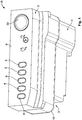
- the lighting device D comprises a casing 3, having a substantially quadrangular shape and formed for example of polymer material (polycarbonate). Inside the casing 3, a printed circuit board 2 is arranged, which defines a main side 20 on which there are positioned side by side a plurality of lighting sources 1, for example solid-state light radiation sources, such as LED sources which emit coloured light.
- the casing 3 further comprises one or more input ports for corresponding electrical connectors and a power button 22.
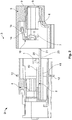
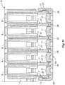
- Fig. 3 is a sectional perspective view of a preferred embodiment of the device D in a partially exploded configuration
- the lighting sources 1 are oriented so as to project their light radiation away from the main side 20 of the printed circuit board 2, in a direction perpendicular to the principal plane of the printed circuit board 2.
- the casing 3 of the device D is defined by a first support body 4, configured to support the printed circuit board 2 in a horizontal direction, and a second support body 5 which, in the mounted configuration, is rigidly connected to the first support body 4 so as to form the casing 3 specified above.
- the first and the second support body 4, 5 are rigidly interconnected by a laser-welding process.
- the first support body 4 has a thickened part 12 protruding from the external walls of the first support body 4, in a direction perpendicular to these walls, and set up to be joined to a corresponding front surface of the second support body 5 so as to form a single hollow casing 3, in the interior of which all the components of the device D are arranged.
- the casing 3 may be formed using other construction techniques and materials which differ from what is specified above, without departing from the scope of the present invention as a result.
- the printed circuit board 2 on which the lighting sources 1 are arranged is supported in a horizontal direction by the first support body 4. More particularly, the board 2 is fixed on the guides 40, 41 within the support body 4, in such a way that the main side 20 of the board 2 is in contact with the guide 40 while the secondary side 23 of the board 2 is in contact with the guide 41 ( Fig. 2 ).
- the second support body 5 comprises in the interior thereof a seat 6 set up to receive an end 21 of the printed circuit board 2, in such a way that, in the mounted configuration of the device D, the lighting sources 1 mounted on the board 2 come to be arranged within the second support body 5.
- the second support body 5 has a plurality of channel-shaped portions 7 arranged side by side and configured to receive in the interior thereof a corresponding lighting source 1 mounted on the printed circuit board 2.
- the channel-shaped portions 7 extend in a direction substantially parallel to the horizontal direction in which the printed circuit board 2 is supported.
- Each channel-shaped portion 7 comprises a first end 70, which is open and faces towards the first support body 4, and a second, opposite end defined by a lens 8 which is set up to emit the light radiation generated by the corresponding lighting source 1 arranged within one of the channel-shaped portions 7.
- the lenses 8 may be formed of transparent polycarbonate, so as to bring about optimum emission of the light radiation emitted from the corresponding lighting sources 1. Moreover, the internal walls of the channel-shaped portions 7 may also be covered in the same material, so as to be able to convey the light of the lighting sources 1 to the corresponding lens 8.
- the lighting sources 1 are oriented so as to project the light radiation thereof away from the main side 20 of the printed circuit board 2, in a direction perpendicular to the principal plane of the printed circuit board 2. This orientation is necessitated by the spaces provided for installing the sources 1 and by the type of sources with which the device is to be implemented (for example LEDs which emit coloured light).
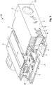
- the lighting device D further comprises a reflector element 10 configured to direct and to improve the homogeneity of the light rays emitted from the lighting sources 1 onto the corresponding lenses 8.
- the accompanying drawings show various example embodiments of the reflector element 10 which defines a principal plane of reflection 13 ( Fig. 5 , 12 , 13 ).
- the reflector element 10 is rigidly connected by means of connecting members to the second support body 5, so that, in the mounted state, it comes to be arranged transversely along the first ends 70 of the channel-shaped portions 7 and directed perpendicular to the principal plane of the printed circuit board 2 and to the principal direction of the channel-shaped portions 7.
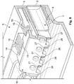
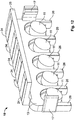
- the principal plane of reflection 13 has a plurality of reflective surfaces 11 arranged side by side, which in the mounted state specified above each face towards a corresponding channel-shaped portion 7, and thus towards a single source of light radiation 1 and the corresponding lens 8 ( Fig. 4 ).
- the reflector element 10 is formed, separate from the printed circuit board 2, as a single component which acts on the light radiation emitted from all the lighting sources 1.
- the reflective surfaces 11 are shaped so as to be configured to direct and to improve the homogeneity of the light rays emitted from a light source 1 onto the corresponding lens 8.
- the reflector element 10 may be formed in a single piece of plastics material (for example polycarbonate) which is white in colour, in order to maximise the effectiveness of its reflective properties.
- the series of reflective surfaces 11 arranged on the principal plane of reflection 13 of the reflector element 10 are separated along the principal plane 13 by a plurality of partition walls 26 ( Fig. 5 , 12 ).
- the partition walls 26 are configured to be arranged, in the mounted state of the device D, in abutment against corresponding dividing walls 27 of the channel-shaped portions 7 ( Fig. 10 , 11 ).
- the light radiation emitted from a single lighting source 1 arranged within one of the channel-shaped portions 7 does not interfere with the light radiation emitted from another lighting source 1 arranged within a channel-shaped portion 7 adjacent to the preceding one.
- the light radiations emitted from the single sources 1 are propagated highly effectively along the respective channel-shaped portions 7 and towards the corresponding lenses 8, without thereby making the structure of the device particularly complex.
- the reflector element 10 is rigidly connected by means of connecting members to the second support body 5.
- connecting members to the second support body 5.
- the reflector element 10 has an upper portion 14 which protrudes in a direction substantially perpendicular to the principal plane of reflection 13.
- a pair of holes 15 are formed, which are intended to be engaged with a corresponding hook portion 16 set up on the second support body 5.
- the hook portion 16 is arranged in an upper position with respect to the channel-shaped portions 7, in such a way that the reflector element 10, in the mounted state, comes to hang from the second support body 5 and covers the first ends 70 of the channel-shaped portions 7 with its principal plane of reflection 13, which carries the reflective surfaces 11 ( Fig. 6-9 ).
- the upper portion 14 of the reflector element 10 has a rounded end edge 19, in such a way that when the upper portion 14 is hooked to the hook portions 16 the reflector element 10 can rotate from a raised position into a position in abutment against the ends 70 of the channel-shaped portions 7 ( Fig. 5-7 ).
- the aforementioned connecting members further include two lateral hooks 17 arranged on the sides of the principal plane 13 of the reflector element 10, which are set up for coupling within corresponding lateral seats 18 arranged on the external sides of the series of channel-shaped portions 7 of the second support element 5 ( Fig. 5 , 9 , 10 ).
- the reflector element 10 includes, as in the embodiment described previously, an upper portion 14 which protrudes from the principal plane of reflection 13 in a direction substantially perpendicular thereto.
- the upper portion 14 has, at the upper surface thereof, a series of ribs 24 set up for mounting the upper portion 14 of the reflective element 10 in an interference fit within a corresponding hook portion 16 formed on the second support body 5.
- the hook portion 16 of the second support body 5 is arranged in an upper position with respect to the channel-shaped portions 7, in such a way that the reflector element 10 is mounted substantially in a transverse direction along the holes 70 in the channel-shaped portions 7.
- the upper portion 14 of the reflector element 10 has a substantially flat end edge 25.
- the connecting members include the two lateral hooks 17 arranged on the sides of the principal plane 13 of the reflector element 10, which are set up for coupling within corresponding lateral seats 18 arranged on the external sides of the series of channel-shaped portions 7 of the second support element 5.
- the reflective surfaces 11, arranged on the principal plane of reflection 13 of the reflector element 10, are separated along the principal plane 13 by a plurality of partition walls 26 which, in the mounted state of the device D, are arranged in abutment against corresponding dividing walls 27 of the channel-shaped portions 7 ( Fig. 10 , 11 ).
- the reflective surfaces 11 may be separated along the principal plane 13 by a plurality of vertical recesses 28.
- the channel-shaped portions 7 are divided from one another by corresponding vertical partition walls 29 which, in the mounted state of the device D, are coupled to the recesses 28 ( Fig. 15 ).
- the reflective surfaces 11 are arranged facing towards a corresponding channel-shaped portion 7, and are configured to direct and to improve the homogeneity of the light rays emitted from a light source 1 onto the corresponding lens 8. Indeed, without the setup of the reflector element 10 and the reflective surfaces 11, given the orientation of the lighting sources 1, the emission of the light radiation onto the lenses 8 would not be very effective, since it would create an inhomogeneous patch of light.
- the reflective surfaces 11 in a first embodiment ( Fig. 4-12 ), have a convex shape, protruding from the plane of reflection 13, and an inclination, with respect to the principal plane of reflection 13, in the direction of the principal plane of the printed circuit board 2 and of the sources 1.
- each reflective surface 11 may include a central cavity 30 ( Fig. 13 , 16-18 ).
- each reflective surface 11 may be associated with a cap 31, likewise of a material having reflective properties, which protrudes from the principal plane of reflection 13 in a direction substantially perpendicular thereto ( Fig. 16 ).
- the reflective surfaces 11 may have a flat surface and an inclination with respect to the principal plane of reflection 13 in the direction of the plane of the printed circuit board 2 and of the sources 1 ( Fig. 17, 18 ).
- each reflective surface may also have, in addition to the central cavity 30 described above, a wavy profile in a portion which is peripheral with respect to said central cavity 30 ( Fig. 19, 20 ).
- one or more embodiments may relate to a device for indicating a charge state of a battery pack mounted on board a motor vehicle powered by an electric motor.
- the present invention further relates to an assembly method for implementing a lighting device, comprising the following steps:
Landscapes
- Engineering & Computer Science (AREA)
- Mechanical Engineering (AREA)
- Transportation (AREA)
- Power Engineering (AREA)
- General Engineering & Computer Science (AREA)
- Life Sciences & Earth Sciences (AREA)
- Sustainable Development (AREA)
- Sustainable Energy (AREA)
- Combustion & Propulsion (AREA)
- Chemical & Material Sciences (AREA)
- Non-Portable Lighting Devices Or Systems Thereof (AREA)
- Fastening Of Light Sources Or Lamp Holders (AREA)
- Aerials With Secondary Devices (AREA)
- Planar Illumination Modules (AREA)
Applications Claiming Priority (1)
| Application Number | Priority Date | Filing Date | Title |
|---|---|---|---|
| IT102019000012951A IT201900012951A1 (it) | 2019-07-25 | 2019-07-25 | Dispositivo di illuminazione provvisto di un elemento riflettore |
Publications (2)
| Publication Number | Publication Date |
|---|---|
| EP3770004A1 true EP3770004A1 (de) | 2021-01-27 |
| EP3770004B1 EP3770004B1 (de) | 2022-03-09 |
Family
ID=69024472
Family Applications (1)
| Application Number | Title | Priority Date | Filing Date |
|---|---|---|---|
| EP20186759.5A Active EP3770004B1 (de) | 2019-07-25 | 2020-07-20 | Mit einem reflektorelement ausgestattete beleuchtungsvorrichtung |
Country Status (3)
| Country | Link |
|---|---|
| US (1) | US11067257B2 (de) |
| EP (1) | EP3770004B1 (de) |
| IT (1) | IT201900012951A1 (de) |
Citations (2)
| Publication number | Priority date | Publication date | Assignee | Title |
|---|---|---|---|---|
| CN105365576A (zh) * | 2015-11-30 | 2016-03-02 | 重庆熠美实业发展有限公司 | 具有能够显示多种充电状态的充电指示灯的电动车 |
| US20160233706A1 (en) * | 2015-02-05 | 2016-08-11 | Hyundai Motor Company | Battery charging status indicator for electric vehicle |
Family Cites Families (12)
| Publication number | Priority date | Publication date | Assignee | Title |
|---|---|---|---|---|
| US5130761A (en) | 1990-07-17 | 1992-07-14 | Kabushiki Kaisha Toshiba | Led array with reflector and printed circuit board |
| JPH10199314A (ja) * | 1997-01-09 | 1998-07-31 | Sony Corp | 導光装置 |
| US6644841B2 (en) | 2002-03-01 | 2003-11-11 | Gelcore Llc | Light emitting diode reflector |
| EP1590996B1 (de) * | 2003-02-07 | 2010-07-14 | Panasonic Corporation | Beleuchtungseinrichtung, einen sockel verwendend, um ein flaches led-modul auf einen kühlkörper zu montieren |
| US7306355B2 (en) * | 2004-07-13 | 2007-12-11 | Gentex Corporation | Optics for controlling the direction of light rays and assemblies incorporating the optics |
| US7521726B2 (en) | 2006-03-15 | 2009-04-21 | Illinois Tool Works Inc. | Collimated LED array with reflector |
| BRPI0921473A2 (pt) * | 2008-10-31 | 2016-01-12 | Code 3 Inc | luminária com refletores calhas internos e externos |
| US8678624B2 (en) * | 2010-10-01 | 2014-03-25 | The Nielsen Company (Us), Llc | Apparatus and methods for illuminating display panels of electronic devices |
| ITTO20121019A1 (it) * | 2012-11-23 | 2014-05-24 | Magneti Marelli Spa | Indicatore a led per formare una barra di luce in una scala grafica |
| KR20150006996A (ko) * | 2013-07-10 | 2015-01-20 | 엘에스산전 주식회사 | 전기 자동차용 충전기 |
| US9568171B1 (en) * | 2016-07-15 | 2017-02-14 | TTP Holdings, LLC | Modular lighting system |
| FR3055258B1 (fr) * | 2016-08-29 | 2018-08-17 | Delphi Technologies, Inc. | Panneau de commande pour vehicule automobile |
-
2019
- 2019-07-25 IT IT102019000012951A patent/IT201900012951A1/it unknown
-
2020
- 2020-07-20 EP EP20186759.5A patent/EP3770004B1/de active Active
- 2020-07-23 US US16/937,105 patent/US11067257B2/en active Active
Patent Citations (2)
| Publication number | Priority date | Publication date | Assignee | Title |
|---|---|---|---|---|
| US20160233706A1 (en) * | 2015-02-05 | 2016-08-11 | Hyundai Motor Company | Battery charging status indicator for electric vehicle |
| CN105365576A (zh) * | 2015-11-30 | 2016-03-02 | 重庆熠美实业发展有限公司 | 具有能够显示多种充电状态的充电指示灯的电动车 |
Also Published As
| Publication number | Publication date |
|---|---|
| IT201900012951A1 (it) | 2021-01-25 |
| US11067257B2 (en) | 2021-07-20 |
| US20210025569A1 (en) | 2021-01-28 |
| EP3770004B1 (de) | 2022-03-09 |
Similar Documents
| Publication | Publication Date | Title |
|---|---|---|
| EP2673165B1 (de) | Scheinwerferanordnung mit planarer kühlkörperstruktur | |
| EP3725584B1 (de) | Ladesäule | |
| US20160149355A1 (en) | Terminal connection device having light source module | |
| EP2292972B1 (de) | Lichtvorrichtung und Fahrzeug mit Beleuchtungsvorrichtung | |
| JP2013521594A (ja) | Led照明素子 | |
| CN105423209B (zh) | 使用多源光学透镜的车辆照明装置 | |
| WO2019213412A1 (en) | Luminaire | |
| CN103562626A (zh) | 照明单元的组装结构 | |
| KR20160082834A (ko) | 차량용 램프 | |
| EP3770004B1 (de) | Mit einem reflektorelement ausgestattete beleuchtungsvorrichtung | |
| CN107166185A (zh) | 一种无缝拼接结构的led灯 | |
| CN209762880U (zh) | 一种路灯发光组件及路灯 | |
| CN217030864U (zh) | 一种多发光点的led灯珠结构 | |
| US20140055256A1 (en) | Charging state displaying device | |
| US20250129924A1 (en) | Optical Plate with Integrated Connection | |
| CN205226917U (zh) | 一种光源模组、照明模组及具有该照明模组的照明灯具 | |
| KR200480185Y1 (ko) | 조립식 조명장치 | |
| CN210372969U (zh) | 一种侧向发光的线条灯 | |
| EP3798502B1 (de) | Plattenleuchte und kit mit der plattenleuchte | |
| CN222780338U (zh) | 一种充电口氛围灯及车辆 | |
| CN214468081U (zh) | 小夜灯 | |
| CA3134054A1 (en) | Light fixture | |
| CN224096735U (zh) | 一种电池箱及具有其的储能系统 | |
| JP6324017B2 (ja) | 車輌用灯具 | |
| JP5988150B2 (ja) | 車両用照明装置 |
Legal Events
| Date | Code | Title | Description |
|---|---|---|---|
| PUAI | Public reference made under article 153(3) epc to a published international application that has entered the european phase |
Free format text: ORIGINAL CODE: 0009012 |
|
| STAA | Information on the status of an ep patent application or granted ep patent |
Free format text: STATUS: THE APPLICATION HAS BEEN PUBLISHED |
|
| AK | Designated contracting states |
Kind code of ref document: A1 Designated state(s): AL AT BE BG CH CY CZ DE DK EE ES FI FR GB GR HR HU IE IS IT LI LT LU LV MC MK MT NL NO PL PT RO RS SE SI SK SM TR |
|
| AX | Request for extension of the european patent |
Extension state: BA ME |
|
| STAA | Information on the status of an ep patent application or granted ep patent |
Free format text: STATUS: REQUEST FOR EXAMINATION WAS MADE |
|
| 17P | Request for examination filed |
Effective date: 20210705 |
|
| RBV | Designated contracting states (corrected) |
Designated state(s): AL AT BE BG CH CY CZ DE DK EE ES FI FR GB GR HR HU IE IS IT LI LT LU LV MC MK MT NL NO PL PT RO RS SE SI SK SM TR |
|
| RIC1 | Information provided on ipc code assigned before grant |
Ipc: B60L 50/64 20190101AFI20210722BHEP Ipc: B60L 58/12 20190101ALI20210722BHEP Ipc: H02J 7/00 20060101ALI20210722BHEP Ipc: F21W 106/00 20180101ALN20210722BHEP |
|
| RIN1 | Information on inventor provided before grant (corrected) |
Inventor name: GENTA, ALESSANDRO Inventor name: FARINOLA, MARCELLO Inventor name: SPOLVERATO, ARIANNA Inventor name: CEZZA, CLAUDIA Inventor name: ALFERI, CINZIA |
|
| RIC1 | Information provided on ipc code assigned before grant |
Ipc: F21W 106/00 20180101ALN20210908BHEP Ipc: H02J 7/00 20060101ALI20210908BHEP Ipc: B60L 58/12 20190101ALI20210908BHEP Ipc: B60L 50/64 20190101AFI20210908BHEP |
|
| GRAP | Despatch of communication of intention to grant a patent |
Free format text: ORIGINAL CODE: EPIDOSNIGR1 |
|
| STAA | Information on the status of an ep patent application or granted ep patent |
Free format text: STATUS: GRANT OF PATENT IS INTENDED |
|
| RIC1 | Information provided on ipc code assigned before grant |
Ipc: F21W 106/00 20180101ALN20211004BHEP Ipc: H02J 7/00 20060101ALI20211004BHEP Ipc: B60L 58/12 20190101ALI20211004BHEP Ipc: B60L 50/64 20190101AFI20211004BHEP |
|
| INTG | Intention to grant announced |
Effective date: 20211026 |
|
| RIN1 | Information on inventor provided before grant (corrected) |
Inventor name: ALFERI, CINZIA Inventor name: CEZZA, CLAUDIA Inventor name: SPOLVERATO, ARIANNA Inventor name: FARINOLA, MARCELLO Inventor name: GENTA, ALESSANDRO |
|
| GRAS | Grant fee paid |
Free format text: ORIGINAL CODE: EPIDOSNIGR3 |
|
| GRAA | (expected) grant |
Free format text: ORIGINAL CODE: 0009210 |
|
| STAA | Information on the status of an ep patent application or granted ep patent |
Free format text: STATUS: THE PATENT HAS BEEN GRANTED |
|
| AK | Designated contracting states |
Kind code of ref document: B1 Designated state(s): AL AT BE BG CH CY CZ DE DK EE ES FI FR GB GR HR HU IE IS IT LI LT LU LV MC MK MT NL NO PL PT RO RS SE SI SK SM TR |
|
| REG | Reference to a national code |
Ref country code: CH Ref legal event code: EP Ref country code: AT Ref legal event code: REF Ref document number: 1473851 Country of ref document: AT Kind code of ref document: T Effective date: 20220315 |
|
| REG | Reference to a national code |
Ref country code: IE Ref legal event code: FG4D |
|
| REG | Reference to a national code |
Ref country code: DE Ref legal event code: R096 Ref document number: 602020002139 Country of ref document: DE |
|
| REG | Reference to a national code |
Ref country code: LT Ref legal event code: MG9D |
|
| REG | Reference to a national code |
Ref country code: NL Ref legal event code: MP Effective date: 20220309 |
|
| PG25 | Lapsed in a contracting state [announced via postgrant information from national office to epo] |
Ref country code: SE Free format text: LAPSE BECAUSE OF FAILURE TO SUBMIT A TRANSLATION OF THE DESCRIPTION OR TO PAY THE FEE WITHIN THE PRESCRIBED TIME-LIMIT Effective date: 20220309 Ref country code: RS Free format text: LAPSE BECAUSE OF FAILURE TO SUBMIT A TRANSLATION OF THE DESCRIPTION OR TO PAY THE FEE WITHIN THE PRESCRIBED TIME-LIMIT Effective date: 20220309 Ref country code: NO Free format text: LAPSE BECAUSE OF FAILURE TO SUBMIT A TRANSLATION OF THE DESCRIPTION OR TO PAY THE FEE WITHIN THE PRESCRIBED TIME-LIMIT Effective date: 20220609 Ref country code: LT Free format text: LAPSE BECAUSE OF FAILURE TO SUBMIT A TRANSLATION OF THE DESCRIPTION OR TO PAY THE FEE WITHIN THE PRESCRIBED TIME-LIMIT Effective date: 20220309 Ref country code: HR Free format text: LAPSE BECAUSE OF FAILURE TO SUBMIT A TRANSLATION OF THE DESCRIPTION OR TO PAY THE FEE WITHIN THE PRESCRIBED TIME-LIMIT Effective date: 20220309 Ref country code: BG Free format text: LAPSE BECAUSE OF FAILURE TO SUBMIT A TRANSLATION OF THE DESCRIPTION OR TO PAY THE FEE WITHIN THE PRESCRIBED TIME-LIMIT Effective date: 20220609 |
|
| REG | Reference to a national code |
Ref country code: AT Ref legal event code: MK05 Ref document number: 1473851 Country of ref document: AT Kind code of ref document: T Effective date: 20220309 |
|
| PG25 | Lapsed in a contracting state [announced via postgrant information from national office to epo] |
Ref country code: LV Free format text: LAPSE BECAUSE OF FAILURE TO SUBMIT A TRANSLATION OF THE DESCRIPTION OR TO PAY THE FEE WITHIN THE PRESCRIBED TIME-LIMIT Effective date: 20220309 Ref country code: GR Free format text: LAPSE BECAUSE OF FAILURE TO SUBMIT A TRANSLATION OF THE DESCRIPTION OR TO PAY THE FEE WITHIN THE PRESCRIBED TIME-LIMIT Effective date: 20220610 Ref country code: FI Free format text: LAPSE BECAUSE OF FAILURE TO SUBMIT A TRANSLATION OF THE DESCRIPTION OR TO PAY THE FEE WITHIN THE PRESCRIBED TIME-LIMIT Effective date: 20220309 |
|
| PG25 | Lapsed in a contracting state [announced via postgrant information from national office to epo] |
Ref country code: NL Free format text: LAPSE BECAUSE OF FAILURE TO SUBMIT A TRANSLATION OF THE DESCRIPTION OR TO PAY THE FEE WITHIN THE PRESCRIBED TIME-LIMIT Effective date: 20220309 |
|
| PG25 | Lapsed in a contracting state [announced via postgrant information from national office to epo] |
Ref country code: SM Free format text: LAPSE BECAUSE OF FAILURE TO SUBMIT A TRANSLATION OF THE DESCRIPTION OR TO PAY THE FEE WITHIN THE PRESCRIBED TIME-LIMIT Effective date: 20220309 Ref country code: SK Free format text: LAPSE BECAUSE OF FAILURE TO SUBMIT A TRANSLATION OF THE DESCRIPTION OR TO PAY THE FEE WITHIN THE PRESCRIBED TIME-LIMIT Effective date: 20220309 Ref country code: RO Free format text: LAPSE BECAUSE OF FAILURE TO SUBMIT A TRANSLATION OF THE DESCRIPTION OR TO PAY THE FEE WITHIN THE PRESCRIBED TIME-LIMIT Effective date: 20220309 Ref country code: PT Free format text: LAPSE BECAUSE OF FAILURE TO SUBMIT A TRANSLATION OF THE DESCRIPTION OR TO PAY THE FEE WITHIN THE PRESCRIBED TIME-LIMIT Effective date: 20220711 Ref country code: ES Free format text: LAPSE BECAUSE OF FAILURE TO SUBMIT A TRANSLATION OF THE DESCRIPTION OR TO PAY THE FEE WITHIN THE PRESCRIBED TIME-LIMIT Effective date: 20220309 Ref country code: EE Free format text: LAPSE BECAUSE OF FAILURE TO SUBMIT A TRANSLATION OF THE DESCRIPTION OR TO PAY THE FEE WITHIN THE PRESCRIBED TIME-LIMIT Effective date: 20220309 Ref country code: CZ Free format text: LAPSE BECAUSE OF FAILURE TO SUBMIT A TRANSLATION OF THE DESCRIPTION OR TO PAY THE FEE WITHIN THE PRESCRIBED TIME-LIMIT Effective date: 20220309 Ref country code: AT Free format text: LAPSE BECAUSE OF FAILURE TO SUBMIT A TRANSLATION OF THE DESCRIPTION OR TO PAY THE FEE WITHIN THE PRESCRIBED TIME-LIMIT Effective date: 20220309 |
|
| PG25 | Lapsed in a contracting state [announced via postgrant information from national office to epo] |
Ref country code: PL Free format text: LAPSE BECAUSE OF FAILURE TO SUBMIT A TRANSLATION OF THE DESCRIPTION OR TO PAY THE FEE WITHIN THE PRESCRIBED TIME-LIMIT Effective date: 20220309 Ref country code: IS Free format text: LAPSE BECAUSE OF FAILURE TO SUBMIT A TRANSLATION OF THE DESCRIPTION OR TO PAY THE FEE WITHIN THE PRESCRIBED TIME-LIMIT Effective date: 20220709 Ref country code: AL Free format text: LAPSE BECAUSE OF FAILURE TO SUBMIT A TRANSLATION OF THE DESCRIPTION OR TO PAY THE FEE WITHIN THE PRESCRIBED TIME-LIMIT Effective date: 20220309 |
|
| REG | Reference to a national code |
Ref country code: DE Ref legal event code: R097 Ref document number: 602020002139 Country of ref document: DE |
|
| PLBE | No opposition filed within time limit |
Free format text: ORIGINAL CODE: 0009261 |
|
| STAA | Information on the status of an ep patent application or granted ep patent |
Free format text: STATUS: NO OPPOSITION FILED WITHIN TIME LIMIT |
|
| PG25 | Lapsed in a contracting state [announced via postgrant information from national office to epo] |
Ref country code: DK Free format text: LAPSE BECAUSE OF FAILURE TO SUBMIT A TRANSLATION OF THE DESCRIPTION OR TO PAY THE FEE WITHIN THE PRESCRIBED TIME-LIMIT Effective date: 20220309 |
|
| 26N | No opposition filed |
Effective date: 20221212 |
|
| PG25 | Lapsed in a contracting state [announced via postgrant information from national office to epo] |
Ref country code: SI Free format text: LAPSE BECAUSE OF FAILURE TO SUBMIT A TRANSLATION OF THE DESCRIPTION OR TO PAY THE FEE WITHIN THE PRESCRIBED TIME-LIMIT Effective date: 20220309 Ref country code: MC Free format text: LAPSE BECAUSE OF FAILURE TO SUBMIT A TRANSLATION OF THE DESCRIPTION OR TO PAY THE FEE WITHIN THE PRESCRIBED TIME-LIMIT Effective date: 20220309 |
|
| REG | Reference to a national code |
Ref country code: BE Ref legal event code: MM Effective date: 20220731 |
|
| PG25 | Lapsed in a contracting state [announced via postgrant information from national office to epo] |
Ref country code: LU Free format text: LAPSE BECAUSE OF NON-PAYMENT OF DUE FEES Effective date: 20220720 |
|
| PG25 | Lapsed in a contracting state [announced via postgrant information from national office to epo] |
Ref country code: BE Free format text: LAPSE BECAUSE OF NON-PAYMENT OF DUE FEES Effective date: 20220731 |
|
| PG25 | Lapsed in a contracting state [announced via postgrant information from national office to epo] |
Ref country code: IE Free format text: LAPSE BECAUSE OF NON-PAYMENT OF DUE FEES Effective date: 20220720 |
|
| REG | Reference to a national code |
Ref country code: CH Ref legal event code: PL |
|
| PG25 | Lapsed in a contracting state [announced via postgrant information from national office to epo] |
Ref country code: MK Free format text: LAPSE BECAUSE OF FAILURE TO SUBMIT A TRANSLATION OF THE DESCRIPTION OR TO PAY THE FEE WITHIN THE PRESCRIBED TIME-LIMIT Effective date: 20220309 Ref country code: CY Free format text: LAPSE BECAUSE OF FAILURE TO SUBMIT A TRANSLATION OF THE DESCRIPTION OR TO PAY THE FEE WITHIN THE PRESCRIBED TIME-LIMIT Effective date: 20220309 Ref country code: CH Free format text: LAPSE BECAUSE OF NON-PAYMENT OF DUE FEES Effective date: 20230731 |
|
| PG25 | Lapsed in a contracting state [announced via postgrant information from national office to epo] |
Ref country code: HU Free format text: LAPSE BECAUSE OF FAILURE TO SUBMIT A TRANSLATION OF THE DESCRIPTION OR TO PAY THE FEE WITHIN THE PRESCRIBED TIME-LIMIT; INVALID AB INITIO Effective date: 20200720 |
|
| PG25 | Lapsed in a contracting state [announced via postgrant information from national office to epo] |
Ref country code: TR Free format text: LAPSE BECAUSE OF FAILURE TO SUBMIT A TRANSLATION OF THE DESCRIPTION OR TO PAY THE FEE WITHIN THE PRESCRIBED TIME-LIMIT Effective date: 20220309 |
|
| PG25 | Lapsed in a contracting state [announced via postgrant information from national office to epo] |
Ref country code: MT Free format text: LAPSE BECAUSE OF FAILURE TO SUBMIT A TRANSLATION OF THE DESCRIPTION OR TO PAY THE FEE WITHIN THE PRESCRIBED TIME-LIMIT Effective date: 20220309 |
|
| GBPC | Gb: european patent ceased through non-payment of renewal fee |
Effective date: 20240720 |
|
| PG25 | Lapsed in a contracting state [announced via postgrant information from national office to epo] |
Ref country code: GB Free format text: LAPSE BECAUSE OF NON-PAYMENT OF DUE FEES Effective date: 20240720 |
|
| PGFP | Annual fee paid to national office [announced via postgrant information from national office to epo] |
Ref country code: FR Payment date: 20250610 Year of fee payment: 6 |
|
| PGFP | Annual fee paid to national office [announced via postgrant information from national office to epo] |
Ref country code: DE Payment date: 20250604 Year of fee payment: 6 |
|
| PGFP | Annual fee paid to national office [announced via postgrant information from national office to epo] |
Ref country code: IT Payment date: 20250623 Year of fee payment: 6 |