EP3769818B1 - Fallschutzgegengewichtsvorrichtung - Google Patents
Fallschutzgegengewichtsvorrichtung Download PDFInfo
- Publication number
- EP3769818B1 EP3769818B1 EP19382635.1A EP19382635A EP3769818B1 EP 3769818 B1 EP3769818 B1 EP 3769818B1 EP 19382635 A EP19382635 A EP 19382635A EP 3769818 B1 EP3769818 B1 EP 3769818B1
- Authority
- EP
- European Patent Office
- Prior art keywords
- counterweight
- base plate
- elements
- tubular body
- projecting
- Prior art date
- Legal status (The legal status is an assumption and is not a legal conclusion. Google has not performed a legal analysis and makes no representation as to the accuracy of the status listed.)
- Active
Links
Images




Classifications
-
- A—HUMAN NECESSITIES
- A62—LIFE-SAVING; FIRE-FIGHTING
- A62B—DEVICES, APPARATUS OR METHODS FOR LIFE-SAVING
- A62B35/00—Safety belts or body harnesses; Similar equipment for limiting displacement of the human body, especially in case of sudden changes of motion
- A62B35/0043—Lifelines, lanyards, and anchors therefore
- A62B35/0068—Anchors
Definitions
- the present invention relates to a fall-protection counterweight apparatus for counterbalancing the weight of a user of a fall-protection element, in particular a fall-protection element of the type comprising a mast.
- the counterweight apparatus is of the type comprising a mast receiving module for housing the mast of the fall-protection element, and a base module provided with a plurality of support legs for ensuring the stable support of the counterweight apparatus on a surface, either on a terrain, the floor slab of a building under construction, etc.
- Document GB2330169-A discloses a deadweight anchor for use as a safety anchor to support a horizontal lifeline for workers on flat-roofed buildings in the event of a fall, comprising two deformable members in the form of strips or planks orthogonally disposed. The ends of each deformable member are connected by means locking members to weights and a pedestal with a point of attachment to the user's rope is provided at the upper deformable member, the pedestal being joined to the other member by means of a threaded shank.
- the force applied to the deadweight anchor as a result of a fall causes the deformable members to buckle and absorb some of the energy of the fall and the anchor moves a distance along the roof surface.
- an individual fall-protection device is the one described in patent document EP1400642-B1 , particularly indicated for work on horizontal surfaces in construction works, in which the anchoring means are made up of an anchoring element, suitable for being inserted into a mass of concrete or mortar in a fluid state, and remaining solidified to the same after the setting or hardening of said mass.
- the safety device is essentially characterised in that the attachment means are made up of a mast, removably coupled at its lower part to said anchoring element with the possibility of pivoting on its vertical axis, and attached, at its upper part, to the upper end of a rope which, at its lower end is linked to the mentioned fastening means, the rope being able to rotate with respect to the vertical axis of the mast, such that the operator is firmly fastened with the possibility of moving freely within an essentially circular field of action, around said vertical axis.
- the anchoring element is a sleeve which receives in its interior the lower end of the mast with the possibility of pivoting on its vertical axis.
- the attachment means further comprise an upper rotating member, attached to the mast, with the possibility of rotating with respect to the latter on its vertical axis.
- said upper rotating member comprises a rotating jib into the free end of which the upper end of the rope is fixed.
- the device may comprise an arm fitted with a fixed or movable compensating ballast at the opposite end of the rotating jib.
- the rope comprises energy absorbing means, adapted for preventing the operator from suffering an impact by the jerking of the rope in the event of an accidental fall.
- FIG. 1 Another device example is the one described in patent application EP3002044-A1 , which discloses a fall-protection system for securely coupling a user to a support structure.
- This fall-protection system comprises a mast arranged to be vertically mounted in a state of use, having a top end and a base end; a user connection assembly; and a tether connector; wherein the mast comprises a structure connection portion, in which the mast is arranged to be removably connected to the support structure, and an energy absorbing deformation portion positioned closer to the top end than the structure connection portion.
- One of the figures of document EP3002044-A1 illustrates how the fall-protection system is mounted in a type of support structure, which consists of a transportable anchor, which in short comprises a frame structure and counterweights, such as concrete weights, placed in the frame structure.
- the transportable anchor further has an anchoring member which receives the structure connection portion of the mast of the protection system.
- the transportable anchor is used in situations when a user is going to work on the roof of a lorry.
- Document ES2639164-T3 describes a fall-protection counterweight apparatus for counterbalancing the weight of a user.
- the apparatus has a top module having a plurality of horizontal members that support a plurality of top leg couplers and a mast coupler; a base module having a plurality of horizontal members, each of the horizontal members extending between a pair of base leg couplers; a stowage module coupled to the base module and arranged within an interior region coplanar with the horizontal members of the base module; and a plurality of legs.
- the top module In a fall-protection mode adapted for operation, the top module is spaced apart from the base module by the plurality of legs, each of the legs being releasably coupled at opposing ends to one of the top leg couplers and one of the base leg couplers. In contrast, in a low profile mode adapted for storage, the top module is directly coupled to the base module coupled by one of the corresponding top base leg couplers, each of the legs arranged within the stowage module.
- WO 2017/203349 A1 discloses a fall-protection counterweight apparatus with a mast receiving module and a mast.
- An objective of the present invention is to disclose an alternative to these known counterweight apparatus or structures, the assembly of which is easy and intuitive, with simple components that can be adapted to the counterweight needs accordingly. Furthermore, the use thereof must be comfortable and simple, without requiring considerable space for the on-site assembly and disassembly, and it must provide the necessary safety at all times in apparatus of this type against slipping and unwanted or accidental extractions of the elements or materials performing the counterweight function.
- a fall-protection counterweight apparatus for counterbalancing the weight of a user of a fall-protection element with a mast.
- the counterweight apparatus comprises a mast receiving module and a base module provided with a plurality of support legs.
- the counterweight apparatus object of the invention is characterised in that the base module is formed by a base plate provided on its lower face with a plurality of leveling support legs for the horizontal arrangement of the base plate, and provided on its upper face with a plurality of projecting elements extending from the base plate in the direction perpendicular to the upper face of the base plate, said projecting elements being provided for fixing counterweight elements that are arranged on the base plate.
- the counterweight apparatus object of the invention is also characterised in that the mast receiving module is arranged on the upper face of the base plate and comprises a tubular body, the hollow of which is sized for tightly housing the mast of a fall-protection element.
- the base plate is a plate arranged horizontally and can be a flat plate, a plate with folds or a pressed plate. It is preferably a metal plate, although manufacturing it in another material capable of withstanding the stress generated by the user of the fall-protection element, the mast of which is tightly housed in the tubular body of the mast receiving module, is not ruled out.
- the base plate extends horizontally covering a distance between leveling support legs spanning a large dimensional range, for example from 500 mm to 2000 mm.
- the base plate can have any type of geometric shape (circular, square, polygonal, arbitrary, etc.), provided that its shape allows supporting the same on a plurality of leveling support legs, as a minimum three legs and preferably four.
- the leveling support legs have a key profile for the manual level adjustment thereof and are attached to the base plate through threaded pins protruding from the lower face of the base plate.
- these threaded pins are welded to the lower face of the base plate.
- a glass or aluminium surface level device to verify the correct level of the upper face of the base plate, i.e., to confirm that the base plate is arranged horizontally and if it is not, to correct the level thereof by adjusting the different support legs with the key.
- leveling legs can be stiff, as indicated above, or alternatively, they may comprise ball joints to ensure better adaptation to any type of terrain.
- leveling support legs with a ball joint are also screwed on threaded pins projecting from the lower face of the base plate, preferably welded to said face.
- the base module represents a structure, the architecture of which facilitates the stock pile and storage thereof.
- the base module is stackable on another base module, and on the upper face of the base plate there are arranged positioning stops protruding from the surface of the upper face of the base plate, partially or completely demarcating a positioning area for the feet of the leveling support legs of a base module stacked thereon.
- These positioning stops can be formed by small plates of any material and be welded or screwed on the upper face of the base plate, in a position above where the leveling support legs of the base module are located.
- the positioning stops can have a curved shape or be banana-shaped to abut with a part of the perimeter of the disc of the foot of the leg of the base module to be stacked on the base plate.
- the mast receiving module comprises the tubular body, the hollow of which is sized for tightly housing the mast of a fall-protection element, said tubular body being provided with an open free end and a closed end.
- the mast receiving module further comprises a coupling support attached to the upper face of the base plate of the base module configured in the form of a plate for coupling the closed end of the tubular body to the base plate.
- the axial axis of the tubular body is arranged in a direction perpendicular to the upper face of the base plate.
- the coupling support can be stiffly attached to the base plate by means of welding or mechanically through a screwed or riveted attachment.
- the closed end of the tubular body is formed by a plate flange in which there are arranged stiffening elements attached to the end part of the tubular body, the tubular body being integrally attached to the plate flange with the axial axis of the tubular body arranged in the direction perpendicular to the plate flange.
- the plate flange and the coupling support are attached to one another by means of a hinged attachment whereby the tubular body, in a non-operative position of the counterweight apparatus, is rotatable with respect to the base plate, the axial axis of the tubular body with respect to the direction perpendicular to the upper face of the base plate forming angles comprised between 90° and 0°.
- the plate flange and the coupling support are attached to one another by means of a screwed attachment whereby the plate flange and the coupling support are arranged in parallel planes without being rotatable with respect to one another.
- the plate flange and the coupling support are attached to one another by means of a screwed attachment, whereby the plate flange and the coupling support are arranged in parallel planes without being rotatable with respect to one another.
- the screwed attachment allows disassembling the plate flange from the coupling support, and with it separating the tubular element from the base plate.
- the tubular body can be provided externally with at least rolling transport means for the tubular body, such as a wheel.
- the tubular body can also be provided with hooking means for the tubular body, for example eyebolt-type means, welded to the surface of the tubular body to facilitate the hooking and subsequent dragging or lifting thereof.
- the projecting elements for fixing counterweight elements are formed by projecting bars integrally or removably attached to the base plate arranged around the tubular body of the mast receiving module, and the counterweight elements are formed by stackable elements provided with a through hole whereby the counterweight element can be inserted on one of the projecting bars forming the plurality of the projecting elements.
- the counterweight elements can be counterweight modules (made of iron, steel, concrete%) in the form of ingots having a through housing, the axis of which is parallel to the projecting element and perpendicular to the two largest faces of the counterweight element.
- the projecting bars can be permanently attached to the base plate by means of welding or they can be mechanically attached elements that can be disassembled. In the event of mechanical attachment, one of the ends must have a projection that screws into a hole made in the base plate.
- each projecting bar is provided at its end farthest away from the base plate with a through hole
- the counterweight apparatus comprises a perimeter safety element to prevent extraction of the counterweight elements provided with two ends, the perimeter safety element being susceptible to being inserted in the through hole of the projecting bars, and the ends of the perimeter safety element being fitted with mutual attachment means, the perimeter safety element determining, with its attached ends, a closed perimeter, arranged through the ends of the projecting bars and around the tubular body, such that the movement capacity of the counterweight elements, stacked and inserted on a projecting bar, along said bar is limited in the lower portion by the upper face of the base plate and in the upper portion by the perimeter safety element.
- the perimeter safety element can be formed by a chain, rope, wire, cable or similar filiform element provided at the ends thereof with a lock to thus ensure that it is not possible to disassemble the counterweight elements that are arranged with the projecting bars of the base module going through them without the corresponding authorisation.
- the upper face of the base plate comprises visual positioning elements for placing the counterweight elements.
- These visual positioning elements can be formed by laminar portions of an anti-attrition material or a non-slip material.
- the visual positioning elements can be, for example, vinyls, gum adhered by adhesive attachment means, or pieces of neoprene glued to the upper face of the base plate.
- the projecting elements for fixing counterweight elements are not formed by projecting bars, but rather the elements are arranged around the tubular body of the mast receiving module and are formed by elements for fixing panels which, when fixed to the projecting elements, form a self-supporting structure having a closed perimeter on the base plate susceptible to depositing within said perimeter a material or materials, the weight of which constitutes the counterweight elements.
- any type of material can be deposited without the particles or elements forming it acquiring a structured arrangement (sand, pieces of steel together with concrete, stones, etc.).
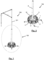
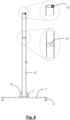
- FIGs 1 , 3 and 4 show a fall-protection element 200, intended for being used by an operator who works at heights, in which the mast 201 is coupled and partially introduced by its lower segment into a counterweight apparatus 100.
- the counterweight apparatus 100 which is shown separately in Figure 2 , basically comprises a mast receiving module and a base module on which are arranged several counterweight elements 17 distributed in stacks.
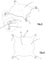
- the base module is formed by a base plate 1 provided on its lower face with a plurality of leveling support legs 2 for the horizontal arrangement of the base plate 1, as shown in Figures 5 and 6 .
- the base plate 1 is preferably a flat plate, although it can be a plate with folds or a pressed plate. Preferably it is a metal plate, although manufacturing it in another material capable of withstanding the stress generated by the user of the fall-protection element 200, the mast 201 of which is tightly housed in the counterweight apparatus 100, is not ruled out.
- the base plate 1 extends horizontally covering a distance between leveling support legs 2 spanning a large dimensional range, for example from 500 mm to 2000 mm.
- the base plate 1 can have any type of geometric shape provided that its shape allows supporting the same on a plurality of leveling support legs 2, as a minimum 3 legs and preferably four, like in the embodiments depicted in the drawings. In the case that is depicted, the base plate 1 has a circular central shape on which the counterweight elements are placed and from which there emerge four prolongations in the radial direction at the ends of which the leveling support legs 2 are located.
- the leveling support legs 2 have a key profile (not depicted) for the manual level adjustment thereof and are attached to the base plate 1 through threaded pins 3 protruding from the lower face of the base plate 1.
- these threaded pins 3 are welded to the lower face of the base plate 1.
- a glass or aluminium surface level device 82 (depicted in the base plate 1 of Figures 10 and 11 ) to verify the correct level of the upper face of the base plate 1, i.e., to confirm that the base plate 1 is arranged horizontally and if it is not, to correct the level thereof by adjusting the different support legs 2 with the key.
- the leveling support legs 2 may comprise ball joints for adapting the feet of the legs to the surface on which the counterweight apparatus 100 is supported.
- the base module is stackable on another base module.
- the base plate 1 there are arranged positioning stops 4 protruding from the surface of the upper face, partially or completely demarcating a positioning area for the feet of the leveling support legs 2 of a base module to be stacked thereon.
- the positioning stops 4 can be formed by small plates of any material and can be welded or screwed on the upper face of the base plate 1.
- the positioning stops 4 can have a curved shape or be banana-shaped to abut with a part of the perimeter of the disc of the foot of the leveling leg 2 of the base module to be stacked on the base plate 1.
- FIG. 5 and 6 there are made on the upper face of the base plate 1 a first series of holes 85 distributed along the circular perimeter of the base plate 1 and a second series of central holes 81.
- the holes 85 of the first series enable the placement of respective projecting elements 5, extending vertically, i.e., in a direction perpendicular to the upper face of the base plate 1, protruding from the same.
- the projecting elements 5, which can be seen in detail in Figures 10 to 12 are used to fix the counterweight elements 17 which are arranged on the upper face of the base plate 1.
- the depicted projecting elements 5 are formed by projecting bars removably attached to the base plate 1 in the positions marked by the holes 85 of the first series, thus being able to easily assemble and disassemble it when the counterweight apparatus 100 is to be put away. Nevertheless, other embodiments in which the projecting bars are integrally attached to the base plate 1 by welding are not ruled out.
- the counterweight elements 17 are formed by stackable elements provided with a through hole 83 (see one of the enlarged detail views of Figure 12 ) whereby the counterweight element 17 can be inserted on one of the projecting bars.
- the counterweight elements 17 can be counterweight modules (made of iron, steel, concrete%) in the form of ingots, stackable one on top of another, having a through hole, the axis of which is parallel to the projecting element 5 and perpendicular to the two largest faces of the counterweight element 17.
- each projecting element 5 can be permanently attached to the base plate 1 by means of welding or they can be mechanically attached elements that can be disassembled.
- each projecting element 5 has at its lower end a protuberance 51 provided with a threaded outer surface complementary to the threading of one of the holes 85 of the first series made in the base plate 1.
- each projecting bar is provided at its end farthest away from the base plate 1 with a through hole 50 adapted for the passage therethrough of a perimeter safety element 18 to prevent extraction of the counterweight elements 17.
- the perimeter safety element 18 can be formed by a chain, rope, wire, cable or similar filiform element provided with two ends 19 (see Figure 10 ). Once the perimeter safety element 18 has been placed going through all the through holes 50 of the projecting bars, said ends 19 are attached to one another, determining a closed perimeter. The ends 19 can be attached through a safety latching device, such as a lock, to thus ensure that it is not possible to disassemble the counterweight elements arranged such that the projecting bars of the base module go through them without the corresponding authorisation.
- a safety latching device such as a lock
- the movement capacity of the counterweight elements 17, arranged on top of another forming a stack and inserted on a projecting bar, along said bar is limited in the lower portion by the upper face of the base plate 1 and in the upper portion by the perimeter safety element 18.
- the upper face of the base plate 1 comprises visual positioning elements 20 for placing the counterweight elements 17 which are first supported on the base plate 1 and after which others will be stacked, forming the stacks necessary for counterbalancing the weight of the user of the fall-protection element 200.
- These visual positioning elements 20 can be formed by laminar portions of an anti-attrition material or a non-slip material to prevent the counterweight elements 17 from moving and being able to damage or scratch the surface of the base plate 1.
- the visual positioning elements 20 can be, for example, vinyls, gum adhered by adhesive attachment means, or pieces of neoprene (for example 2 mm thick) glued to the upper face of the base plate 1.
- the counterweight apparatus 100 comprises a mast receiving module arranged on the upper face of the base plate 1, comprising a tubular body 6, the hollow of which is sized for tightly housing the mast 201 of the fall-protection element 200, and a coupling support 7 attached to the upper face of the base plate 1 in which it is centrally arranged.
- the tubular body 6 is provided with an upper open free end and with a lower closed end, as indicated in Figures 7 and 8 .
- FIG 8 it can be seen how the tubular body 6 has, inserted in the area of the upper end forming an insertion opening for inserting the end of the mast 201, an upper guide component 13, and spaced a certain distance below, the tubular body 6 has an additional guide component 14 therein.
- These guide components act like elements for fastening the mast 201 to keep it within the tubular body 6 in a tight and vertical position.
- the lower end of the tubular body 6 is closed by its attachment to the coupling support 7 fixedly attached to the upper face of the base plate, either by welding or preferably by a screwed attachment in which the screws 8 (see Figure 7 ) are introduced in the holes 81 that are internally threaded for that purpose and provided in the central area of the base plate 1.
- stiffening elements 12 To reinforce the attachment between the tubular body 6 and the coupling support 7, there are arranged stiffening elements 12.
- FIG. 9 another preferred embodiment of the counterweight apparatus 100 has been depicted in which the lower end of the tubular body 6 is closed by its attachment to a plate flange 11 in which there are arranged stiffening elements 12 attached to the end part of the tubular body 6.
- the tubular body 6 is integrally attached to the plate flange 11 with the axial axis of the tubular body 6 arranged in the direction perpendicular to the plate flange 11.
- the plate flange 11 and the coupling support 7 are attached to one another by means of a hinged attachment 10 whereby the tubular body 6, in a non-operative position of the counterweight apparatus 100, is rotatable with respect to the base plate 1, the axial axis of the tubular body 6 with respect to the direction perpendicular to the upper face of the base plate 1 forming angles comprised between 90° and 0°.
- the plate flange 11 and the coupling support 7 are attached to one another by means of a screwed attachment (see screws 8) whereby the plate flange 11 and the coupling support 7 are arranged in parallel planes, with the axial axis of the tubular body 6 in the direction perpendicular to the base plate 1.
- the counterweight apparatus 100 is shown in detail in an operative position, prepared for receiving the mast 201 in the tubular body 6 and counterbalancing the weight of the user of the fall-protection element 200.
- the projecting elements 5 for fixing counterweight elements 17 are arranged around the tubular body 6 of the mast receiving module.
- the tubular body 6 is provided with rolling transport means 15 such as a wheel, and with hooking means 16 for the tubular body 6, for example eyebolt-type means, welded to the surface of the tubular body 6 to facilitate the hooking and subsequent dragging or lifting thereof.
- the assembly of the counterweight apparatus is very simple and intuitive for users.
- the base plate 1 is placed on the surface of the terrain or ground where the operator using the fall-protection element 200 will be working.
- the tubular body 6 is transported to said location with the help of the rolling transport means 5 or by means of lifting and moving it with a crane by means of the hooking means 16.
- the coupling support 7 is centrally placed on the base plate 1.
- the coupling support 7 has a series of through holes which have to be matched up with the holes 81 made in the base plate 1.
- the base plate 1 may already have the coupling support 7 placed in its central part, for example previously attached by welding to the base plate 1.
- the tubular body 6 has one of its ends closed by its attachment to a plate flange 11, additionally provided with stiffening elements 12 and threaded through holes provided for the passage therethrough of screws 8
- the plate flange 11 is coupled to the coupling support 7 through the hinged attachment 10 and the tubular body 6 will be rotated until the plate flange 11 is supported on the coupling support 7 and the tubular body 6 is an essentially vertical position, perpendicular to the base plate 1.
- the plate flange 11 will be screwed to the coupling support 7.
- the base plate 1 not to have any coupling support 7 previously attached or screwed to its central part, but rather for the tubular body 6 that has been moved to the base plate 1 to have its end closed by the plate flange 11 and for this plate flange 11 to already be hingedly attached to the coupling support 7.
- the tubular body 6 is arranged perpendicular to the base plate 1 and supported on the same by means of the coupling support 7 and the plate flange 11 arranged parallel to the base plate 1.
- the hinged assembly will be attached by screwing to the base plate 1 by means of inserting the screws 8 into the holes 81.
- tubular body 6 is not of the type provided with a plate flange 11, its end intended for being the lower end will be attached to the coupling support 7, in turn attached to the base plate 1, either by welding, by screwed attachment, riveted attachment, etc.
- visual positioning elements 20 for placing the counterweight elements 17 to be stacked one on top of another can be arranged in the base plate 1.
- These visual positioning elements 20 have holes in the positions of the holes 85 of the base plate 1, and the projecting elements 5 in the form of projecting bars are vertically placed in these positions.
- the projecting elements 5 preferably have a threaded protuberance 51 for the threaded attachment with the complementary threaded holes 85.
- the holes 85 can simply be blind holes for fitting the lower end of the projecting bars.
- each counterweight element 17 in the form of ingots or prisms having a base that is larger than their height and provided with holes 83 for being placed threaded on the projecting elements 5, are inserted on same, as shown in Figure 12 .
- the lower face of each counterweight element 17 is provided with a notch fitting with the shape of a protuberance provided on its upper face to facilitate mutual fitting when the counterweight elements 17 are stacked one on top of another and thus form straight stacks in which the counterweight elements 17 do not move with respect to one another.
- the perimeter safety element 18 is placed to prevent extraction of the counterweight elements 17, passing one of the ends 19 through the through holes 50 of all the projecting elements 5 in the form of bars.
- the ends 19 are attached to one another by a safety lock and the counterweight elements 17 therefore cannot be extracted without authorisation.
- the counterweight apparatus 100 is in the operative position, like that of Figure 2 , and is ready for the tubular body 6 to tightly receive in its hollow the mast 201 of the fall-protection element 200; at that point the operator or user can already use said protection element with guarantees that their movements will not entail any risk as their weight and that of the protection element are counterbalanced by the counterweight apparatus 100.
- the mast 201 is extracted and the counterweight apparatus 100 disassembled, inversely performing the operations carried out for assembly.
- the base modules may be stacked since the positioning stops 4 are arranged protruding on the surface of the upper face of the base plates 1, partially or completely demarcating a positioning area for the feet of the leveling support legs 2 of a base module to be stacked thereon.
- the projecting elements 5 for fixing counterweight elements 17 are not formed by projecting bars, but rather the projecting elements, likewise arranged around the tubular body 6, are formed by elements for fixing panels which, when fixed to the projecting elements 5, form a self-supporting structure having a closed perimeter on the base plate 1 susceptible to depositing within said perimeter a material or materials, the weight of which constitutes the counterweight elements 17.
- any type of material can be deposited without the particles or elements forming it acquiring a structured arrangement (sand, pieces of steel together with concrete, stones, etc.).
Landscapes
- Health & Medical Sciences (AREA)
- General Health & Medical Sciences (AREA)
- Business, Economics & Management (AREA)
- Emergency Management (AREA)
- Cage And Drive Apparatuses For Elevators (AREA)
- Emergency Lowering Means (AREA)
Claims (15)
- Fallschutzgegengewichtsvorrichtung (100) zum Gewichtsausgleich des Gewichts eines Benutzers eines Fallschutzelements (200) mit einem Mast (201), in welchem die Gegengewichtsvorrichtung (100) ein Mastaufnahmemodul und ein Basismodul, welches mit einer Vielzahl von Stützbeinen versehen ist, umfasst, wobei das Basismodul aus einer Basisplatte (1) gebildet ist, welche auf deren untere Fläche mit einer Vielzahl von Nivellierungsstützbeinen (2) für die horizontale Anordnung der Basisplatte (1) versehen ist und auf deren oberen Fläche mit einer Vielzahl von herausragenden Elementen (5) versehen ist, welche sich von der Basisplatte (1) aus in der Richtung senkrecht zur oberen Fläche der Basisplatte (1) erstrecken, um Gegengewichtselemente (17), welche auf der Basisplatte (1) angeordnet sind, zu fixieren, und wobei das Mastaufnahmemodul auf der oberen Fläche der Basisplatte angeordnet ist und einen rohrförmigen Körper (6) umfasst, dessen Aushöhlung dimensioniert ist, um den Mast (201) eines Fallschutzelements (200) eng aufzunehmen.
- Gegengewichtsvorrichtung (100) nach Anspruch 1, dadurch gekennzeichnet, dass die Nivellierungsstützbeine (2) ein Schlüsselprofil für die manuelle Niveaueinstellung derselben aufweisen und mit der Basisplatte (1) über Gewindestifte (3) verbunden sind, welche aus der unteren Fläche der Basisplatte (1) herausragen.
- Gegengewichtsvorrichtung (100) nach Anspruch 1 oder 2, dadurch gekennzeichnet, dass die Nivellierungsstützbeine (2) Kugelgelenke umfassen, um die Füße der Beine an die Oberfläche, auf welcher die Gegengewichtsvorrichtung (100) gestützt ist, anzupassen.
- Gegengewichtsvorrichtung (100) nach einem der vorhergehenden Ansprüche, dadurch gekennzeichnet, dass das Basismodul auf einem anderen Basismodul stapelbar ist, wobei auf der oberen Fläche der Basisplatte (1) Positionieranschläge (4) angeordnet sind, welche aus der Oberfläche der oberen Fläche herausragen, unter teilweiser oder vollständiger Abgrenzung eines Positionierbereichs für die Füße der Nivellierungsstützbeine (2) eines Basismodul, welches darauf gestapelt werden kann.
- Gegengewichtsvorrichtung (100) nach einem der vorhergehenden Ansprüche, dadurch gekennzeichnet, dass die Basisplatte (1) im Wesentlichen flach ist.
- Gegengewichtsvorrichtung (100) nach einem der vorhergehenden Ansprüche, dadurch gekennzeichnet, dass der rohrförmige Körper (6) des Mastaufnahmemoduls mit einem offenen freien Ende und mit einem geschlossenen Ende versehen ist, wobei das Mastaufnahmemodul zusätzlich eine Kopplungsstütze (7), welche mit der oberen Fläche der Basisplatte (1) des Basismoduls verbunden ist, welche in Form einer Platte zur Kopplung des rohrförmigen Körpers (6) mit der Basisplatte (1) ausgebildet ist, umfasst, wobei die axiale Achse des rohrförmigen Körpers (6) in einer Betriebsstellung der Gegengewichtsvorrichtung (100) ist, welche in einer Richtung senkrecht zur oberen Fläche der Basisplatte (1) angeordnet ist.
- Gegengewichtsvorrichtung (100) nach Anspruch 6, dadurch gekennzeichnet, dass das geschlossene Ende des rohrförmigen Körpers (6) aus einem Plattenflansch (11) gebildet ist, in welchem Versteifungselemente (12) angeordnet sind, welche mit dem Endteil des rohrförmigen Körpers (6) verbunden sind, wobei der rohrförmige Körper (6) integral mit dem Plattenflansch (11) verbunden ist, wobei die axiale Achse des rohrförmigen Körpers (6) in der Richtung senkrecht zum Plattenflansch (11) angeordnet ist.
- Gegengewichtsvorrichtung (100) nach Anspruch 7, dadurch gekennzeichnet, dass der Plattenflansch (11) und die Kopplungsstütze (7) mittels einer Scharnierverbindung (10) miteinander verbunden sind, wodurch der rohrförmige Körper (6), in einer Nichtbetriebsstellung der Gegengewichtsvorrichtung (100), in Bezug auf die Basisplatte (1) rotierbar ist, wobei die axiale Achse des rohrförmigen Körpers (6) in Bezug auf die Richtung senkrecht zur oberen Fläche der Basisplatte (1) Winkel bildet, welche zwischen 90° und 0° liegen.
- Gegengewichtsvorrichtung (100) nach Anspruch 6 oder 7, dadurch gekennzeichnet, dass der Plattenflansch (11) und die Kopplungsstütze (7) in einer Betriebsstellung mittels einer geschraubten Verbindung miteinander verbunden sind, wodurch der Plattenflansch (11) und die Kopplungsstütze (7) in parallelen Ebenen angeordnet sind.
- Gegengewichtsvorrichtung (100) nach einem der Ansprüche 6 bis 9, dadurch gekennzeichnet, dass der rohrförmige Körper (6) mit mindestens rollenden Transportmitteln (15), wie ein Rad, und mit Einhakmitteln (16) für den rohrförmigen Körper (6) versehen ist.
- Gegengewichtsvorrichtung (100) nach einem der vorhergehenden Ansprüche, dadurch gekennzeichnet, dass die herausragenden Elemente (5) zum Fixieren von Gegengewichtselementen (17) aus herausragenden Stangen gebildet sind, welche integral oder lösbar mit der Basisplatte (1) verbunden sind und um den rohrförmigen Körper (6) des Mastaufnahmemoduls herum angeordnet sind, und dass die Gegengewichtselemente (17) aus stapelbaren Elementen gebildet sind, welche mit einem Durchgangsloch versehen sind, durch welches das Gegengewichtselement (7) an einer der herausragenden Stangen, welche die Vielzahl von den herausragenden Elementen (5) bilden, eingesetzt werden kann.
- Gegengewichtsvorrichtung (100) nach Anspruch 11, dadurch gekennzeichnet, dass jede herausragende Stange an deren Ende, welches am weitesten von der Basisplatte (1) liegt, mit einem Durchgangsloch (50) versehen ist, und dass die Gegengewichtsvorrichtung (100) ein Umfangssicherheitselement (18) umfasst, um die Entnahme der mit zwei Enden versehenen Gegengewichtselemente (17) zu verhindern, wobei das Umfangssicherheitselement (18) in das Durchgangsloch (50) der herausragenden Stangen eingesetzt werden kann und wobei die Enden (19) des Umfangssicherheitselements (18) mit gegenseitigen Verbindungsmitteln ausgerüstet sind, wobei das Umfangssicherheitselement (18), mit deren verbundenen Enden, einen geschlossenen Umfang bestimmt, welcher durch die Enden der herausragenden Stangen und um den rohrförmigen Körper (6) herum angeordnet ist, sodass die Bewegungsfähigkeit der Gegengewichtselemente (17), gestapelt und an einer herausragenden Stange eingesetzt, entlang der genannten Stange im unteren Teil von der oberen Fläche der Basisplatte (1) und im oberen Teil vom Umfangssicherheitselement (18) beschränkt ist.
- Gegengewichtsvorrichtung (100) nach Anspruch 11 oder 12, dadurch gekennzeichnet, dass die obere Fläche der Basisplatte (1) visuelle Positionierelemente (20) zum Platzieren der Gegengewichtselemente (17) umfasst.
- Gegengewichtsvorrichtung (100) nach Anspruch 13, dadurch gekennzeichnet, dass die visuelle Positionierelemente (20) zum Platzieren der Gegengewichtselemente (17) aus flächenförmigen Teilen eines Anti-Abrieb-Materials oder eines rutschfesten Materials gebildet sind.
- Gegengewichtsvorrichtung (100) nach einem der Ansprüche 1 bis 10, dadurch gekennzeichnet, dass die herausragenden Elementen (5) zum Fixieren von Gegengewichtselementen (17) um den rohrförmigen Körper (6) des Mastaufnahmemoduls herum angeordnet sind und aus Elementen zum Fixieren von Paneelen gebildet sind, welche, wenn sie an den herausragenden Elementen (5) fixiert sind, eine selbsttragende Struktur aufweisend einen geschlossenen Umfang auf der Basisplatte (1) bilden, innerhalb deren Umfangs ein Material oder Materialien gelegt werden können, dessen/deren Gewicht die Gegengewichtselemente (17) bildet.
Priority Applications (3)
| Application Number | Priority Date | Filing Date | Title |
|---|---|---|---|
| PL19382635.1T PL3769818T3 (pl) | 2019-07-25 | 2019-07-25 | Urządzenie zabezpieczające przed upadkiem z masą bezwładnościową |
| ES19382635T ES2981486T3 (es) | 2019-07-25 | 2019-07-25 | Un aparato contrapesado de protección contra caídas |
| EP19382635.1A EP3769818B1 (de) | 2019-07-25 | 2019-07-25 | Fallschutzgegengewichtsvorrichtung |
Applications Claiming Priority (1)
| Application Number | Priority Date | Filing Date | Title |
|---|---|---|---|
| EP19382635.1A EP3769818B1 (de) | 2019-07-25 | 2019-07-25 | Fallschutzgegengewichtsvorrichtung |
Publications (3)
| Publication Number | Publication Date |
|---|---|
| EP3769818A1 EP3769818A1 (de) | 2021-01-27 |
| EP3769818B1 true EP3769818B1 (de) | 2024-05-01 |
| EP3769818C0 EP3769818C0 (de) | 2024-05-01 |
Family
ID=67658320
Family Applications (1)
| Application Number | Title | Priority Date | Filing Date |
|---|---|---|---|
| EP19382635.1A Active EP3769818B1 (de) | 2019-07-25 | 2019-07-25 | Fallschutzgegengewichtsvorrichtung |
Country Status (3)
| Country | Link |
|---|---|
| EP (1) | EP3769818B1 (de) |
| ES (1) | ES2981486T3 (de) |
| PL (1) | PL3769818T3 (de) |
Family Cites Families (5)
| Publication number | Priority date | Publication date | Assignee | Title |
|---|---|---|---|---|
| GB2330169B (en) * | 1997-09-18 | 2001-09-19 | Dunn & Cowe Ltd | Improved deadweight anchor |
| ES2178610B1 (es) | 2001-06-04 | 2004-09-01 | Encofrados J. Alsina, S.A. | Dispositivo de seguridad para trabajos sobre superficies horizontales en obras de construccion. |
| EP2999523B1 (de) | 2013-05-23 | 2017-04-26 | Honeywell International Inc. | Gegengewicht für sturzsicherungsapparate mti niedrigem profil |
| EP3002044B1 (de) | 2014-09-30 | 2022-11-02 | Honeywell International Inc. | Sturzsicherungssystem |
| ITUA20164298A1 (it) * | 2016-05-23 | 2017-11-23 | Cdr Italy | Dispositivo di sicurezza anticaduta |
-
2019
- 2019-07-25 ES ES19382635T patent/ES2981486T3/es active Active
- 2019-07-25 EP EP19382635.1A patent/EP3769818B1/de active Active
- 2019-07-25 PL PL19382635.1T patent/PL3769818T3/pl unknown
Also Published As
| Publication number | Publication date |
|---|---|
| ES2981486T3 (es) | 2024-10-09 |
| PL3769818T3 (pl) | 2024-07-08 |
| EP3769818A1 (de) | 2021-01-27 |
| EP3769818C0 (de) | 2024-05-01 |
Similar Documents
| Publication | Publication Date | Title |
|---|---|---|
| US10329781B2 (en) | Safety barrier netting system | |
| US6151851A (en) | Stackable support column system and method for multistory building construction | |
| US20100012427A1 (en) | Mobile anchoring and fall prevention device | |
| US20090120718A1 (en) | Multi-level safety net support system for high-rise construction | |
| CN101103161A (zh) | 建筑物建造中使用的设备 | |
| KR102097909B1 (ko) | 공간확장형 조립식 가설 작업대 | |
| WO2009009898A1 (en) | Concrete slab depth varying system | |
| US7896132B2 (en) | Multi-level fall protection system for high-rise construction | |
| RU2400609C2 (ru) | Комплексная система обеспечения техники безопасности в строительстве | |
| US7836656B2 (en) | Tower module, system and method | |
| US20120312940A1 (en) | Mobile anchoring and fall prevention device | |
| US7735606B1 (en) | Scaffold support platform | |
| EP3769818B1 (de) | Fallschutzgegengewichtsvorrichtung | |
| JP4101232B2 (ja) | 昇降可能な仮設足場を用いた建設物の施工方法 | |
| US20070096006A1 (en) | Overhead beam assembly | |
| KR101300982B1 (ko) | 인양 레일용 레일 스톱퍼 | |
| AU2008100567A4 (en) | A scaffolding stand for use in a formwork support system | |
| RU2383701C2 (ru) | Передвижные подмости | |
| JP7245472B2 (ja) | 飛散防止システムおよび既存建物の解体方法 | |
| AU2010101120A4 (en) | Scaffolding system | |
| KR200251745Y1 (ko) | 수평 방호망 장치 | |
| EP1941114A2 (de) | Überkopfträgeranordnung | |
| KR200465039Y1 (ko) | 높은 기둥 설치작업용 비계 | |
| NL2023549B1 (nl) | Werkwijze voor het bouwen van een voor personen toegankelijk gebouw | |
| CA2599534A1 (en) | Concrete slab depth varying system |
Legal Events
| Date | Code | Title | Description |
|---|---|---|---|
| PUAI | Public reference made under article 153(3) epc to a published international application that has entered the european phase |
Free format text: ORIGINAL CODE: 0009012 |
|
| STAA | Information on the status of an ep patent application or granted ep patent |
Free format text: STATUS: THE APPLICATION HAS BEEN PUBLISHED |
|
| AK | Designated contracting states |
Kind code of ref document: A1 Designated state(s): AL AT BE BG CH CY CZ DE DK EE ES FI FR GB GR HR HU IE IS IT LI LT LU LV MC MK MT NL NO PL PT RO RS SE SI SK SM TR |
|
| AX | Request for extension of the european patent |
Extension state: BA ME |
|
| STAA | Information on the status of an ep patent application or granted ep patent |
Free format text: STATUS: REQUEST FOR EXAMINATION WAS MADE |
|
| 17P | Request for examination filed |
Effective date: 20210628 |
|
| RBV | Designated contracting states (corrected) |
Designated state(s): AL AT BE BG CH CY CZ DE DK EE ES FI FR GB GR HR HU IE IS IT LI LT LU LV MC MK MT NL NO PL PT RO RS SE SI SK SM TR |
|
| GRAP | Despatch of communication of intention to grant a patent |
Free format text: ORIGINAL CODE: EPIDOSNIGR1 |
|
| STAA | Information on the status of an ep patent application or granted ep patent |
Free format text: STATUS: GRANT OF PATENT IS INTENDED |
|
| INTG | Intention to grant announced |
Effective date: 20231205 |
|
| GRAS | Grant fee paid |
Free format text: ORIGINAL CODE: EPIDOSNIGR3 |
|
| GRAA | (expected) grant |
Free format text: ORIGINAL CODE: 0009210 |
|
| STAA | Information on the status of an ep patent application or granted ep patent |
Free format text: STATUS: THE PATENT HAS BEEN GRANTED |
|
| AK | Designated contracting states |
Kind code of ref document: B1 Designated state(s): AL AT BE BG CH CY CZ DE DK EE ES FI FR GB GR HR HU IE IS IT LI LT LU LV MC MK MT NL NO PL PT RO RS SE SI SK SM TR |
|
| REG | Reference to a national code |
Ref country code: GB Ref legal event code: FG4D |
|
| REG | Reference to a national code |
Ref country code: CH Ref legal event code: EP |
|
| REG | Reference to a national code |
Ref country code: IE Ref legal event code: FG4D |
|
| REG | Reference to a national code |
Ref country code: DE Ref legal event code: R096 Ref document number: 602019051306 Country of ref document: DE |
|
| U01 | Request for unitary effect filed |
Effective date: 20240521 |
|
| U07 | Unitary effect registered |
Designated state(s): AT BE BG DE DK EE FI FR IT LT LU LV MT NL PT SE SI Effective date: 20240603 |
|
| U20 | Renewal fee for the european patent with unitary effect paid |
Year of fee payment: 6 Effective date: 20240730 |
|
| PG25 | Lapsed in a contracting state [announced via postgrant information from national office to epo] |
Ref country code: IS Free format text: LAPSE BECAUSE OF FAILURE TO SUBMIT A TRANSLATION OF THE DESCRIPTION OR TO PAY THE FEE WITHIN THE PRESCRIBED TIME-LIMIT Effective date: 20240901 |
|
| REG | Reference to a national code |
Ref country code: ES Ref legal event code: FG2A Ref document number: 2981486 Country of ref document: ES Kind code of ref document: T3 Effective date: 20241009 |
|
| PG25 | Lapsed in a contracting state [announced via postgrant information from national office to epo] |
Ref country code: HR Free format text: LAPSE BECAUSE OF FAILURE TO SUBMIT A TRANSLATION OF THE DESCRIPTION OR TO PAY THE FEE WITHIN THE PRESCRIBED TIME-LIMIT Effective date: 20240501 |
|
| PG25 | Lapsed in a contracting state [announced via postgrant information from national office to epo] |
Ref country code: GR Free format text: LAPSE BECAUSE OF FAILURE TO SUBMIT A TRANSLATION OF THE DESCRIPTION OR TO PAY THE FEE WITHIN THE PRESCRIBED TIME-LIMIT Effective date: 20240802 |
|
| PG25 | Lapsed in a contracting state [announced via postgrant information from national office to epo] |
Ref country code: NO Free format text: LAPSE BECAUSE OF FAILURE TO SUBMIT A TRANSLATION OF THE DESCRIPTION OR TO PAY THE FEE WITHIN THE PRESCRIBED TIME-LIMIT Effective date: 20240801 Ref country code: IS Free format text: LAPSE BECAUSE OF FAILURE TO SUBMIT A TRANSLATION OF THE DESCRIPTION OR TO PAY THE FEE WITHIN THE PRESCRIBED TIME-LIMIT Effective date: 20240901 Ref country code: HR Free format text: LAPSE BECAUSE OF FAILURE TO SUBMIT A TRANSLATION OF THE DESCRIPTION OR TO PAY THE FEE WITHIN THE PRESCRIBED TIME-LIMIT Effective date: 20240501 Ref country code: GR Free format text: LAPSE BECAUSE OF FAILURE TO SUBMIT A TRANSLATION OF THE DESCRIPTION OR TO PAY THE FEE WITHIN THE PRESCRIBED TIME-LIMIT Effective date: 20240802 Ref country code: RS Free format text: LAPSE BECAUSE OF FAILURE TO SUBMIT A TRANSLATION OF THE DESCRIPTION OR TO PAY THE FEE WITHIN THE PRESCRIBED TIME-LIMIT Effective date: 20240801 |
|
| PG25 | Lapsed in a contracting state [announced via postgrant information from national office to epo] |
Ref country code: CZ Free format text: LAPSE BECAUSE OF FAILURE TO SUBMIT A TRANSLATION OF THE DESCRIPTION OR TO PAY THE FEE WITHIN THE PRESCRIBED TIME-LIMIT Effective date: 20240501 |
|
| PG25 | Lapsed in a contracting state [announced via postgrant information from national office to epo] |
Ref country code: SK Free format text: LAPSE BECAUSE OF FAILURE TO SUBMIT A TRANSLATION OF THE DESCRIPTION OR TO PAY THE FEE WITHIN THE PRESCRIBED TIME-LIMIT Effective date: 20240501 Ref country code: RO Free format text: LAPSE BECAUSE OF FAILURE TO SUBMIT A TRANSLATION OF THE DESCRIPTION OR TO PAY THE FEE WITHIN THE PRESCRIBED TIME-LIMIT Effective date: 20240501 |
|
| PG25 | Lapsed in a contracting state [announced via postgrant information from national office to epo] |
Ref country code: SM Free format text: LAPSE BECAUSE OF FAILURE TO SUBMIT A TRANSLATION OF THE DESCRIPTION OR TO PAY THE FEE WITHIN THE PRESCRIBED TIME-LIMIT Effective date: 20240501 |
|
| PG25 | Lapsed in a contracting state [announced via postgrant information from national office to epo] |
Ref country code: SM Free format text: LAPSE BECAUSE OF FAILURE TO SUBMIT A TRANSLATION OF THE DESCRIPTION OR TO PAY THE FEE WITHIN THE PRESCRIBED TIME-LIMIT Effective date: 20240501 Ref country code: SK Free format text: LAPSE BECAUSE OF FAILURE TO SUBMIT A TRANSLATION OF THE DESCRIPTION OR TO PAY THE FEE WITHIN THE PRESCRIBED TIME-LIMIT Effective date: 20240501 Ref country code: RO Free format text: LAPSE BECAUSE OF FAILURE TO SUBMIT A TRANSLATION OF THE DESCRIPTION OR TO PAY THE FEE WITHIN THE PRESCRIBED TIME-LIMIT Effective date: 20240501 Ref country code: CZ Free format text: LAPSE BECAUSE OF FAILURE TO SUBMIT A TRANSLATION OF THE DESCRIPTION OR TO PAY THE FEE WITHIN THE PRESCRIBED TIME-LIMIT Effective date: 20240501 |
|
| REG | Reference to a national code |
Ref country code: DE Ref legal event code: R097 Ref document number: 602019051306 Country of ref document: DE |
|
| PG25 | Lapsed in a contracting state [announced via postgrant information from national office to epo] |
Ref country code: MC Free format text: LAPSE BECAUSE OF FAILURE TO SUBMIT A TRANSLATION OF THE DESCRIPTION OR TO PAY THE FEE WITHIN THE PRESCRIBED TIME-LIMIT Effective date: 20240501 |
|
| REG | Reference to a national code |
Ref country code: CH Ref legal event code: PL |
|
| PLBE | No opposition filed within time limit |
Free format text: ORIGINAL CODE: 0009261 |
|
| STAA | Information on the status of an ep patent application or granted ep patent |
Free format text: STATUS: NO OPPOSITION FILED WITHIN TIME LIMIT |
|
| 26N | No opposition filed |
Effective date: 20250204 |
|
| PG25 | Lapsed in a contracting state [announced via postgrant information from national office to epo] |
Ref country code: CH Free format text: LAPSE BECAUSE OF NON-PAYMENT OF DUE FEES Effective date: 20240731 |
|
| PG25 | Lapsed in a contracting state [announced via postgrant information from national office to epo] |
Ref country code: IE Free format text: LAPSE BECAUSE OF NON-PAYMENT OF DUE FEES Effective date: 20240725 |
|
| U20 | Renewal fee for the european patent with unitary effect paid |
Year of fee payment: 7 Effective date: 20250728 |
|
| PGFP | Annual fee paid to national office [announced via postgrant information from national office to epo] |
Ref country code: ES Payment date: 20250821 Year of fee payment: 7 |
|
| PGFP | Annual fee paid to national office [announced via postgrant information from national office to epo] |
Ref country code: PL Payment date: 20250714 Year of fee payment: 7 |
|
| PGFP | Annual fee paid to national office [announced via postgrant information from national office to epo] |
Ref country code: GB Payment date: 20250710 Year of fee payment: 7 |
|
| PG25 | Lapsed in a contracting state [announced via postgrant information from national office to epo] |
Ref country code: CY Free format text: LAPSE BECAUSE OF FAILURE TO SUBMIT A TRANSLATION OF THE DESCRIPTION OR TO PAY THE FEE WITHIN THE PRESCRIBED TIME-LIMIT; INVALID AB INITIO Effective date: 20190725 |
|
| PG25 | Lapsed in a contracting state [announced via postgrant information from national office to epo] |
Ref country code: HU Free format text: LAPSE BECAUSE OF FAILURE TO SUBMIT A TRANSLATION OF THE DESCRIPTION OR TO PAY THE FEE WITHIN THE PRESCRIBED TIME-LIMIT; INVALID AB INITIO Effective date: 20190725 |