EP3769805A2 - Motoranordnung für eine katheterpumpe - Google Patents
Motoranordnung für eine katheterpumpe Download PDFInfo
- Publication number
- EP3769805A2 EP3769805A2 EP20187258.7A EP20187258A EP3769805A2 EP 3769805 A2 EP3769805 A2 EP 3769805A2 EP 20187258 A EP20187258 A EP 20187258A EP 3769805 A2 EP3769805 A2 EP 3769805A2
- Authority
- EP
- European Patent Office
- Prior art keywords
- drive
- magnet
- assembly
- driven
- housing
- Prior art date
- Legal status (The legal status is an assumption and is not a legal conclusion. Google has not performed a legal analysis and makes no representation as to the accuracy of the status listed.)
- Pending
Links
Images


Classifications
-
- A—HUMAN NECESSITIES
- A61—MEDICAL OR VETERINARY SCIENCE; HYGIENE
- A61M—DEVICES FOR INTRODUCING MEDIA INTO, OR ONTO, THE BODY; DEVICES FOR TRANSDUCING BODY MEDIA OR FOR TAKING MEDIA FROM THE BODY; DEVICES FOR PRODUCING OR ENDING SLEEP OR STUPOR
- A61M60/00—Blood pumps; Devices for mechanical circulatory actuation; Balloon pumps for circulatory assistance
- A61M60/40—Details relating to driving
- A61M60/403—Details relating to driving for non-positive displacement blood pumps
- A61M60/419—Details relating to driving for non-positive displacement blood pumps the force acting on the blood contacting member being permanent magnetic, e.g. from a rotating magnetic coupling between driving and driven magnets
-
- A—HUMAN NECESSITIES
- A61—MEDICAL OR VETERINARY SCIENCE; HYGIENE
- A61M—DEVICES FOR INTRODUCING MEDIA INTO, OR ONTO, THE BODY; DEVICES FOR TRANSDUCING BODY MEDIA OR FOR TAKING MEDIA FROM THE BODY; DEVICES FOR PRODUCING OR ENDING SLEEP OR STUPOR
- A61M60/00—Blood pumps; Devices for mechanical circulatory actuation; Balloon pumps for circulatory assistance
- A61M60/10—Location thereof with respect to the patient's body
- A61M60/122—Implantable pumps or pumping devices, i.e. the blood being pumped inside the patient's body
- A61M60/126—Implantable pumps or pumping devices, i.e. the blood being pumped inside the patient's body implantable via, into, inside, in line, branching on, or around a blood vessel
- A61M60/13—Implantable pumps or pumping devices, i.e. the blood being pumped inside the patient's body implantable via, into, inside, in line, branching on, or around a blood vessel by means of a catheter allowing explantation, e.g. catheter pumps temporarily introduced via the vascular system
-
- A—HUMAN NECESSITIES
- A61—MEDICAL OR VETERINARY SCIENCE; HYGIENE
- A61M—DEVICES FOR INTRODUCING MEDIA INTO, OR ONTO, THE BODY; DEVICES FOR TRANSDUCING BODY MEDIA OR FOR TAKING MEDIA FROM THE BODY; DEVICES FOR PRODUCING OR ENDING SLEEP OR STUPOR
- A61M60/00—Blood pumps; Devices for mechanical circulatory actuation; Balloon pumps for circulatory assistance
- A61M60/20—Type thereof
- A61M60/205—Non-positive displacement blood pumps
- A61M60/216—Non-positive displacement blood pumps including a rotating member acting on the blood, e.g. impeller
-
- A—HUMAN NECESSITIES
- A61—MEDICAL OR VETERINARY SCIENCE; HYGIENE
- A61M—DEVICES FOR INTRODUCING MEDIA INTO, OR ONTO, THE BODY; DEVICES FOR TRANSDUCING BODY MEDIA OR FOR TAKING MEDIA FROM THE BODY; DEVICES FOR PRODUCING OR ENDING SLEEP OR STUPOR
- A61M60/00—Blood pumps; Devices for mechanical circulatory actuation; Balloon pumps for circulatory assistance
- A61M60/40—Details relating to driving
- A61M60/403—Details relating to driving for non-positive displacement blood pumps
- A61M60/422—Details relating to driving for non-positive displacement blood pumps the force acting on the blood contacting member being electromagnetic, e.g. using canned motor pumps
-
- A—HUMAN NECESSITIES
- A61—MEDICAL OR VETERINARY SCIENCE; HYGIENE
- A61M—DEVICES FOR INTRODUCING MEDIA INTO, OR ONTO, THE BODY; DEVICES FOR TRANSDUCING BODY MEDIA OR FOR TAKING MEDIA FROM THE BODY; DEVICES FOR PRODUCING OR ENDING SLEEP OR STUPOR
- A61M60/00—Blood pumps; Devices for mechanical circulatory actuation; Balloon pumps for circulatory assistance
- A61M60/50—Details relating to control
- A61M60/508—Electronic control means, e.g. for feedback regulation
- A61M60/515—Regulation using real-time patient data
-
- A—HUMAN NECESSITIES
- A61—MEDICAL OR VETERINARY SCIENCE; HYGIENE
- A61M—DEVICES FOR INTRODUCING MEDIA INTO, OR ONTO, THE BODY; DEVICES FOR TRANSDUCING BODY MEDIA OR FOR TAKING MEDIA FROM THE BODY; DEVICES FOR PRODUCING OR ENDING SLEEP OR STUPOR
- A61M60/00—Blood pumps; Devices for mechanical circulatory actuation; Balloon pumps for circulatory assistance
- A61M60/50—Details relating to control
- A61M60/508—Electronic control means, e.g. for feedback regulation
- A61M60/538—Regulation using real-time blood pump operational parameter data, e.g. motor current
-
- A—HUMAN NECESSITIES
- A61—MEDICAL OR VETERINARY SCIENCE; HYGIENE
- A61M—DEVICES FOR INTRODUCING MEDIA INTO, OR ONTO, THE BODY; DEVICES FOR TRANSDUCING BODY MEDIA OR FOR TAKING MEDIA FROM THE BODY; DEVICES FOR PRODUCING OR ENDING SLEEP OR STUPOR
- A61M60/00—Blood pumps; Devices for mechanical circulatory actuation; Balloon pumps for circulatory assistance
- A61M60/80—Constructional details other than related to driving
- A61M60/802—Constructional details other than related to driving of non-positive displacement blood pumps
- A61M60/804—Impellers
- A61M60/806—Vanes or blades
- A61M60/808—Vanes or blades specially adapted for deformable impellers, e.g. expandable impellers
-
- A—HUMAN NECESSITIES
- A61—MEDICAL OR VETERINARY SCIENCE; HYGIENE
- A61M—DEVICES FOR INTRODUCING MEDIA INTO, OR ONTO, THE BODY; DEVICES FOR TRANSDUCING BODY MEDIA OR FOR TAKING MEDIA FROM THE BODY; DEVICES FOR PRODUCING OR ENDING SLEEP OR STUPOR
- A61M60/00—Blood pumps; Devices for mechanical circulatory actuation; Balloon pumps for circulatory assistance
- A61M60/80—Constructional details other than related to driving
- A61M60/855—Constructional details other than related to driving of implantable pumps or pumping devices
- A61M60/865—Devices for guiding or inserting pumps or pumping devices into the patient's body
-
- A—HUMAN NECESSITIES
- A61—MEDICAL OR VETERINARY SCIENCE; HYGIENE
- A61M—DEVICES FOR INTRODUCING MEDIA INTO, OR ONTO, THE BODY; DEVICES FOR TRANSDUCING BODY MEDIA OR FOR TAKING MEDIA FROM THE BODY; DEVICES FOR PRODUCING OR ENDING SLEEP OR STUPOR
- A61M60/00—Blood pumps; Devices for mechanical circulatory actuation; Balloon pumps for circulatory assistance
- A61M60/80—Constructional details other than related to driving
- A61M60/855—Constructional details other than related to driving of implantable pumps or pumping devices
- A61M60/871—Energy supply devices; Converters therefor
- A61M60/88—Percutaneous cables
-
- A—HUMAN NECESSITIES
- A61—MEDICAL OR VETERINARY SCIENCE; HYGIENE
- A61M—DEVICES FOR INTRODUCING MEDIA INTO, OR ONTO, THE BODY; DEVICES FOR TRANSDUCING BODY MEDIA OR FOR TAKING MEDIA FROM THE BODY; DEVICES FOR PRODUCING OR ENDING SLEEP OR STUPOR
- A61M60/00—Blood pumps; Devices for mechanical circulatory actuation; Balloon pumps for circulatory assistance
- A61M60/10—Location thereof with respect to the patient's body
- A61M60/122—Implantable pumps or pumping devices, i.e. the blood being pumped inside the patient's body
- A61M60/126—Implantable pumps or pumping devices, i.e. the blood being pumped inside the patient's body implantable via, into, inside, in line, branching on, or around a blood vessel
- A61M60/148—Implantable pumps or pumping devices, i.e. the blood being pumped inside the patient's body implantable via, into, inside, in line, branching on, or around a blood vessel in line with a blood vessel using resection or like techniques, e.g. permanent endovascular heart assist devices
-
- A—HUMAN NECESSITIES
- A61—MEDICAL OR VETERINARY SCIENCE; HYGIENE
- A61M—DEVICES FOR INTRODUCING MEDIA INTO, OR ONTO, THE BODY; DEVICES FOR TRANSDUCING BODY MEDIA OR FOR TAKING MEDIA FROM THE BODY; DEVICES FOR PRODUCING OR ENDING SLEEP OR STUPOR
- A61M60/00—Blood pumps; Devices for mechanical circulatory actuation; Balloon pumps for circulatory assistance
- A61M60/40—Details relating to driving
- A61M60/403—Details relating to driving for non-positive displacement blood pumps
- A61M60/408—Details relating to driving for non-positive displacement blood pumps the force acting on the blood contacting member being mechanical, e.g. transmitted by a shaft or cable
- A61M60/411—Details relating to driving for non-positive displacement blood pumps the force acting on the blood contacting member being mechanical, e.g. transmitted by a shaft or cable generated by an electromotor
- A61M60/414—Details relating to driving for non-positive displacement blood pumps the force acting on the blood contacting member being mechanical, e.g. transmitted by a shaft or cable generated by an electromotor transmitted by a rotating cable, e.g. for blood pumps mounted on a catheter
-
- Y—GENERAL TAGGING OF NEW TECHNOLOGICAL DEVELOPMENTS; GENERAL TAGGING OF CROSS-SECTIONAL TECHNOLOGIES SPANNING OVER SEVERAL SECTIONS OF THE IPC; TECHNICAL SUBJECTS COVERED BY FORMER USPC CROSS-REFERENCE ART COLLECTIONS [XRACs] AND DIGESTS
- Y10—TECHNICAL SUBJECTS COVERED BY FORMER USPC
- Y10T—TECHNICAL SUBJECTS COVERED BY FORMER US CLASSIFICATION
- Y10T29/00—Metal working
- Y10T29/49—Method of mechanical manufacture
- Y10T29/49229—Prime mover or fluid pump making
- Y10T29/49236—Fluid pump or compressor making
Definitions
- This application is directed to catheter pumps for mechanical circulatory support of a heart.
- Heart disease is a major health problem that has high mortality rate. Physicians increasingly use mechanical circulatory support systems for treating heart failure. The treatment of acute heart failure requires a device that can provide support to the patient quickly. Physicians desire treatment options that can be deployed quickly and minimally-invasively.
- Intra-aortic balloon pumps are currently the most common type of circulatory support devices for treating acute heart failure.
- IABPs are commonly used to treat heart failure, such as to stabilize a patient after cardiogenic shock, during treatment of acute myocardial infarction (MI) or decompensated heart failure, or to support a patient during high risk percutaneous coronary intervention (PCI).
- Circulatory support systems may be used alone or with pharmacological treatment.
- an IABP is positioned in the aorta and actuated in a counterpulsation fashion to provide partial support to the circulatory system.
- More recently minimally-invasive rotary blood pump have been developed in an attempt to increase the level of potential support (i.e., higher flow).
- a rotary blood pump is typically inserted into the body and connected to the cardiovascular system, for example, to the left ventricle and the ascending aorta to assist the pumping function of the heart.
- Other know applications pumping venous blood from the right ventricle to the pulmonary artery for support of the right side of the heart.
- An aim of acute circulatory support devices is to reduce the load on the heart muscle for a period of time, to stabilize the patient prior to heart transplant or for continuing support.
- a pump with improved performance and clinical outcomes.
- a pump that can provide elevated flow rates with reduced risk of hemolysis and thrombosis.
- a pump that can be inserted minimally-invasively and provide sufficient flow rates for various indications while reducing the risk of major adverse events.
- a heart pump that can be placed minimally-invasively, for example, through a 15FR or 12FR incision.
- a heart pump that can provide an average flow rate of 4 Lpm or more during operation, for example, at 62 mmHg of head pressure.
- a motor configured to drive an operative device, e.g., a impeller, at a distal portion of the pump. It can be important for the motor to be configured to allow for percutaneous insertion of the pump's operative device.
- a catheter pump in one embodiment, can include a catheter assembly.
- the catheter assembly can include a drive shaft having a proximal end and a distal end.
- An impeller may be coupled with the distal end of the drive shaft.
- a driven magnet assembly may be coupled with the proximal end of the drive shaft.
- the driven magnet assembly can include a driven magnet housing having a driven magnet.
- the catheter pump can further include a drive system.
- the drive system can include a motor having an output shaft.
- the drive system can also include a drive magnet assembly coupled with the output shaft.
- the drive magnet assembly can include a drive magnet housing with a drive magnet disposed therein.
- a securement device can be configured to secure the driven magnet housing into engagement with the drive magnet housing during operation of the pump.
- a catheter pump in another embodiment, can include a catheter assembly.
- the catheter assembly can comprise a drive shaft having a proximal end and a distal end.
- An impeller can be coupled with the distal end of the drive shaft.
- a rotatable magnet can be coupled with the proximal end.
- the rotatable magnet can be disposed in a driven magnet housing.
- the catheter pump can include a drive system comprising a plurality of motor windings configured to induce rotation of the rotatable magnet when the driven magnet housing is engaged with the drive system.
- a locking device can be configured to be engaged by insertion of the driven magnet housing into an opening of the drive system.
- a method in yet another embodiment, can include inserting a proximal portion of a catheter assembly containing a magnet into a recess of a drive unit. The method can further include engaging a locking device to secure the proximal portion of the catheter assembly to the drive unit.
- a catheter assembly in another embodiment, can include a catheter body having a proximal portion and a distal portion.
- An operative device can be coupled to the distal portion of the catheter body.
- a tip member can be coupled to a distal portion of the operative device.
- the tip member can have a lumen comprising a first section and a second section connected to the first section. An inner diameter of the first section can be larger than an inner diameter of the second section.
- a catheter pump in one embodiment, includes a catheter assembly and a drive system, and a securement device.
- the catheter assembly includes a drive shaft, an impeller, and a driven assembly.
- the drive shaft has a proximal end and a distal end.
- the impeller is coupled with the distal end of the drive shaft.
- the driven assembly may be coupled with the proximal end of the drive shaft, the driven assembly is disposed in a driven housing.
- the drive system includes a motor having an output shaft and a drive assembly coupled with the output shaft.
- the drive assembly includes a drive housing with at least one magnet disposed therein.
- the securement device is configured to prevent disengagement of the driven housing from the drive housing during operation of the pump.
- a catheter pump in one embodiment, includes a catheter assembly and a drive system, and a damper.
- the catheter assembly includes a drive shaft, an impeller, and a driven member.
- the drive shaft has a proximal end and a distal end.
- the impeller is coupled with the distal end of the drive shaft.
- the driven member is coupled with the proximal end of the drive shaft.
- the drive system includes a motor having an output shaft and a drive member coupled with the output shaft.
- the catheter pump can have a damper disposed between the drive and driven member.
- the damper can be configured to isolate the drive member or the motor from vibration in the catheter assembly.
- the damper can be configured to suppress noise at or around the connection between the drive and drive members.
- the damper is disposed radially around the output shaft, e.g., completely surrounding the output shaft.
- the damper can be disposed between separable housings of the catheter assembly and drive system, e.g., abutting a distal face of a drive system housing and a proximal face of a driven member housing disposed on the proximal end of the catheter assembly.
- This embodiment can be augmented in some embodiments with a disconnectable coupling between the drive and driven members.
- a securement device can be configured to permit selective disengagement of these components from each other.
- the securement device can be configured to prevent disengagement of the driven housing from the drive housing during operation of the pump.
- connection of the drive and driven members can be by the mutual attraction of opposing poles of permanent magnets disposed therein.
- the driven member can be positioned to be acted upon magnetic fields generated in the winding e.g., using commutation in the windings.
- the drive and driven members are coupled using direct mechanical drive, such as with gears, splines or other abutting surfaces.
- a catheter pump in another embodiment, has a catheter assembly, a drive system, and a locking device.
- the catheter assembly has a drive shaft that has a proximal end and a distal end.
- An impeller is coupled with the distal end of the drive shaft.
- a rotatable magnet is coupled with the proximal end of the drive shaft.
- the rotatable magnet is disposed in a driven magnet housing.
- the drive system has a plurality of motor windings configured to induce rotation of the rotatable magnet after the driven magnet housing is engaged with the drive system.
- the locking device is configured to be engaged by insertion of the driven magnet housing into a portion or recess of the drive system.
- Rotation can be induced in the rotatable magnet by the mutual attraction of opposing poles of permanent magnets.
- the rotatable magnet can be an assembly having one or a first plurality of permanent magnets and one or a second plurality of permanent magnets can be mounted on a shaft of the motor having the motor windings. Pairing of opposite poles of two magnets or of the magnets of the first and second pluralities of permanent magnets can induce rotation that can be transferred to the drive shaft.
- the rotatable magnet can be positioned to be acted upon magnetic fields generated in the winding, e.g., using commutation in the windings.
- a method is provided. A proximal portion of a catheter assembly containing a magnet is inserted into a recess of a drive unit. A locking device is engaged to secure the proximal portion of the catheter assembly to a distal portion of the drive unit.
- an operative device such as an impeller
- an impeller can be coupled at a distal portion of the apparatus.
- the disclosed embodiments generally relate to various configurations for a motor adapted to drive an impeller at a distal end of a catheter pump, e.g., a percutaneous heart pump.
- the disclosed motor assembly may be disposed outside the patient in some embodiments. In other embodiments, the disclosed motor assembly can be miniaturized and sized to be inserted within the body.
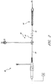
- Figures 1-3 show aspects of a catheter pump 10 that can provide high performance flow rates.
- the pump 10 includes a motor driven by a controller 22.
- the controller 22 directs the operation of the motor 14 and an infusion system 26 that supplies a flow of infusate in the pump 10.
- a catheter system 80 that can be coupled with the motor 14 houses an impeller within a distal portion thereof.
- the impeller is rotated remotely by the motor 14 when the pump 10 is operating.
- the motor 14 can be disposed outside the patient.
- the motor 14 is separate from the controller 22, e.g., to be placed closer to the patient.
- the motor 14 is part of the controller 22.
- the motor is miniaturized to be insertable into the patient.
- Such embodiments allow the drive shaft to be much shorter, e.g., shorter than the distance from the aortic valve to the aortic arch (about 5 cm or less).
- miniaturized motors catheter pumps and related components and methods are discussed in US 5,964,694 ; US6,007,478 ; US6,178,922 ; and US 6,176,848 , all of which are hereby incorporated by reference herein in their entirety for all purposes.
- Various embodiments of a motor are disclosed herein, including embodiments having separate drive and driven assemblies to enable the use of a guidewire guide passing through the catheter pump.
- a guidewire guide can facilitate passing a guidewire through the catheter pump for percutaneous delivery of the pump's operative device to a patient's heart.
- FIG. 3 illustrates one use of the catheter pump 10.
- a distal portion of the pump 10, which can include an impeller assembly 92, is placed in the left ventricle LV of the heart to pump blood from the LV into the aorta.
- the pump 10 can be used in this way to treat patients with a wide range of conditions, including cardiogenic shock, myocardial infarction, and other cardiac conditions, and also to support a patient during a procedure such as percutaneous coronary intervention.
- One convenient manner of placement of the distal portion of the pump 10 in the heart is by percutaneous access and delivery using the Seldinger technique or other methods familiar to cardiologists. These approaches enable the pump 10 to be used in emergency medicine, a catheter lab and in other non-surgical settings.
- Modifications can also enable the pump 10 to support the right side of the heart.
- Example modifications that could be used for right side support include providing delivery features and/or shaping a distal portion that is to be placed through at least one heart valve from the venous side, such as is discussed in US 6,544,216 ; US 7,070,555 ; and US 2012-0203056A1 , all of which are hereby incorporated by reference herein in their entirety for all purposes.
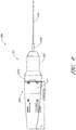
- Figure 2 shows features that facilitate small blood vessel percutaneous delivery and high performance, including up to and in some cases exceeding normal cardiac output in all phases of the cardiac cycle.
- the catheter system 80 includes a catheter body 84 and a sheath assembly 88.
- the impeller assembly 92 is coupled with the distal end of the catheter body 84.
- the impeller assembly 92 is expandable and collapsible. In the collapsed state, the distal end of the catheter system 80 can be advanced to the heart, for example, through an artery. In the expanded state the impeller assembly 92 is able to pump blood at high flow rates.
- Figures 2 and 3 illustrate the expanded state.
- the collapsed state can be provided by advancing a distal end 94 of an elongate body 96 distally over the impeller assembly 92 to cause the impeller assembly 92 to collapse.
- This provides an outer profile throughout the catheter assembly 80 that is of small diameter, for example, to a catheter size of about 12.5 FR in various arrangements.
- the impeller assembly 92 includes a self-expanding material that facilitates expansion.
- the catheter body 84 on the other hand preferably is a polymeric body that has high flexibility. When the impeller assembly 92 is collapsed, as discussed above, high forces are applied to the impeller assembly 92. These forces are concentrated at a connection zone, where the impeller assembly 92 and the catheter body 84 are coupled together. These high forces, if not carefully managed can result in damage to the catheter assembly 80 and in some cases render the impeller within the impeller assembly 92 inoperable. Robust mechanical interface, are provided to assure high performance.
- the mechanical components rotatably supporting the impeller within the impeller assembly 92 permit high rotational speeds while controlling heat and particle generation that can come with high speeds.
- the infusion system 26 delivers a cooling and lubricating solution to the distal portion of the catheter system 80 for these purposes.
- the space for delivery of this fluid is extremely limited. Some of the space is also used for return of the infusate. Providing secure connection and reliable routing of infusate into and out of the catheter assembly 80 is critical and challenging in view of the small profile of the catheter body 84.
- the catheter pump system When activated, the catheter pump system can effectively increase the flow of blood out of the heart and through the patient's vascular system.
- the pump can be configured to produce a maximum flow rate (e.g. low mm Hg) of greater than 4 Lpm, greater than 4.5 Lpm, greater than 5 Lpm, greater than 5.5 Lpm, greater than 6 Lpm, greater than 6.5 Lpm, greater than 7 Lpm, greater than 7.5 Lpm, greater than 8 Lpm, greater than 9 Lpm, or greater than 10 Lpm.
- a maximum flow rate e.g. low mm Hg
- the pump can be configured to produce an average flow rate at 62 mmHg of greater than 2 Lpm, greater than 2.5 Lpm, greater than 3 Lpm, greater than 3.5 Lpm, greater than 4 Lpm, greater than 4.25 Lpm, greater than 4.5 Lpm, greater than 5 Lpm, greater than 5.5 Lpm, or greater than 6 Lpm.
- FIG. 4 Another example of a catheter assembly 100A is illustrated in Figure 4 .
- Embodiments of the catheter pump of this application can be configured with a motor that is capable of coupling to (and in some arrangements optionally decoupling from) the catheter assembly 100A.
- This arrangement provides a number of advantages over a non-disconnectable housing. For example, access can be provided to a proximal end of the catheter assembly 100A prior to or during use.
- a catheter pump is delivered over a guidewire.
- the guidewire may be conveniently extended through the entire length of the catheter assembly 100A and out of a proximal portion thereof that is completely enclosed in a coupled configuration.
- connection of the proximal portion of the catheter assembly 100A to a motor housing can be completed after a guidewire has been used to guide the operative device of the catheter pump to a desired location within the patient, e.g., to a chamber of the patient's heart.
- the connection between the motor housing and the catheter assembly is configured to be permanent, such that the catheter assembly, the motor housing and the motor are disposable components.
- the coupling between the motor housing and the catheter assembly is disengageable, such that the motor and motor housing can be decoupled from the catheter assembly after use.
- the catheter assembly distal of the motor can be disposable, and the motor and motor housing can be re-usable.
- a priming apparatus 1400 can be disposed over an impeller assembly 116A.
- the impeller assembly 116A can include an expandable cannula or housing and an impeller with one or more blades. As the impeller rotates, blood can be pumped proximally (or distally in some implementations) to function as a cardiac assist device.
- Figure 4 also shows one example of a priming apparatus 1400 disposed over the impeller assembly 116A near the distal end 170A of the elongate body 174A.
- Figure 4A is an enlarged view of the priming apparatus 1400 shown in Figure 4 .
- the priming apparatus 1400 can be used in connection with a procedure to expel air from the impeller assembly 116A, e.g., any air that is trapped within the housing or that remains within the elongate body 174A near the distal end 170A.
- the priming procedure may be performed before the pump is inserted into the patient's vascular system, so that air bubbles are not allowed to enter and/or injure the patient.
- the priming apparatus 1400 can include a primer housing 1401 configured to be disposed around both the elongate body 174A and the impeller assembly 116A.
- a sealing cap 1406 can be applied to the proximal end 1402 of the primer housing 1401 to substantially seal the priming apparatus 1400 for priming, i.e., so that air does not proximally enter the elongate body 174A and also so that priming fluid does not flow out of the proximal end of the housing 1401.
- the sealing cap 1406 can couple to the primer housing 1401 in any way known to a skilled artisan.
- the sealing cap 1406 is threaded onto the primer housing by way of a threaded connector 1405 located at the proximal end 1402 of the primer housing 1401.
- the sealing cap 1406 can include a sealing recess disposed at the distal end of the sealing cap 1406.
- the sealing recess can be configured to allow the elongate body 174A to pass through the sealing cap 1406.
- the priming operation can proceed by introducing fluid into the sealed priming apparatus 1400 to expel air from the impeller assembly 116A and the elongate body 174A.
- Fluid can be introduced into the priming apparatus 1400 in a variety of ways.
- fluid can be introduced distally through the elongate body 174A into the priming apparatus 1400.
- an inlet such as a luer, can optionally be formed on a side of the primer housing 1401 to allow for introduction of fluid into the priming apparatus 1400.
- a gas permeable membrane can be disposed on a distal end 1404 of the primer housing 1401.
- the gas permeable membrane can permit air to escape from the primer housing 1401 during priming.
- the priming apparatus 1400 also can advantageously be configured to collapse an expandable portion of the catheter assembly 100A.
- the primer housing 1401 can include a funnel 1415 where the inner diameter of the housing decreases from distal to proximal.
- the funnel may be gently curved such that relative proximal movement of the impeller housing causes the impeller housing to be collapsed by the funnel 1415.
- the distal end 170A of the elongate body 174A can be moved distally relative to the collapsed housing.
- the catheter assembly 100A can be removed from the priming housing 1400 before a percutaneous heart procedure is performed, e.g., before the pump is activated to pump blood.
- the embodiments disclosed herein may be implemented such that the total time for infusing the system is minimized or reduced.
- the time to fully infuse the system can be about six minutes or less.
- the time to infuse can be about three minutes or less.
- the total time to infuse the system can be about 45 seconds or less. It should be appreciated that lower times to infuse can be advantageous for use with cardiovascular patients.
- the elongate body 174A extends proximally from the impeller assembly 116A to an infusate device 195 configured to allow for infusate to enter the catheter assembly 100A and for waste fluid to leave the catheter assembly 100A.
- a catheter body 120A (which also passes through the elongate body 174A) can extend proximally and couple to a driven assembly 201.
- the driven assembly 201 can be configured to receive torque applied by a drive assembly 203, which is shown as being decoupled from the driven assembly 201 and the catheter assembly 100A in Figure 4 .
- a drive shaft can extend from the driven assembly 201 through the catheter body 120A to couple to an impeller shaft at or proximal to the impeller assembly 116A.
- the catheter body 120A can pass within the elongate catheter body 174Asuch that the external catheter body 174A can axially translate relative to the catheter body 120A.
- Figure 4 illustrates a guidewire 235 extending from a proximal guidewire opening 237 in the driven assembly 201.
- a clinician may insert the guidewire 235 through the patient's vascular system to the heart to prepare a path for the operative device (e.g., the impeller assembly 116A) to the heart.
- the catheter assembly can include a guidewire guide tube (see Figure 12 ) passing through a central internal lumen of the catheter assembly 100A from the proximal guidewire opening 237.
- the guidewire guide tube can be preinstalled in the catheter assembly 100A to provide the clinician with a preformed pathway along which to insert the guidewire 235.
- a guidewire is first placed in a conventional way, e.g., through a needle into a peripheral blood vessel, and along the path between that blood vessel and the heart and into a heart chamber, e.g., into the left ventricle. Thereafter, a distal end opening of the catheter assembly or guidewire guide can be advanced over the proximal end of the guidewire 235 to enable delivery to the catheter assembly 100A. After the proximal end of the guidewire 235 is urged proximally within the catheter assembly 100A and emerges from the guidewire opening 237 and/or guidewire guide, the catheter assembly 100A can be advanced into the patient. In one method, the guidewire guide is withdrawn proximally while holding the catheter assembly 100A. The guidewire guide is taken off of the catheter assembly 100A so that guidewire lumens from the proximal end to the distal end of the catheter assembly 100A are directly over the guidewire.
- the clinician can thus insert the guidewire 235 through the proximal guidewire opening 237 and urge the guidewire 235 along the guidewire guide tube until the guidewire 235 extends from a distal guidewire opening (not shown) in the distal end of the catheter assembly 100A.
- the clinician can continue urging the guidewire 235 through the patient's vascular system until the distal end of the guidewire 235 is positioned in the desired chamber of the patient's heart.
- a proximal end portion of the guidewire 235 can extend from the proximal guidewire opening 237.
- the clinician can maneuver the impeller assembly 116A over the guidewire 235 until the impeller assembly 116A reaches the distal end of the guidewire 235 in the heart.
- the clinician can remove the guidewire 235 and the guidewire guide tube.
- the guidewire guide tube can also be removed before or after the guidewire 235 is removed in some implementations.
- the clinician can activate a motor to rotate the impeller and begin operation of the pump.
- a central lumen or tube e.g., a guidewire guide
- a motor or drive assembly having a lumen through which the guidewire 235 can pass.
- the drive assembly 203 can be securely coupled to the driven assembly 201 such that vibratory, axial, or other external forces do not decouple the drive assembly 203 from the driven assembly 201 during operation.
- the coupling should preferably allow a motor to operate effectively so that the drive shaft is rotated at the desired speed and with the desired torque.
- FIG. 5 illustrates one embodiment of a motor assembly 206 as the driven assembly 201 is being coupled to the drive assembly 203.
- the driven assembly 201 can include a flow diverter 205 and a flow diverter housing 207 that houses the flow diverter 205.
- the flow diverter 205 can be configured with a plurality of internal cavities, passages, and channels that are configured to route fluid to and from the patient during a medical procedure.
- an infusate can be directed into the flow diverter from a source of infusate.
- the infusate is a fluid that flows into the catheter body 120A to provide useful benefits, such as cooling moving parts and keeping blood from entering certain parts of the catheter assembly 100A.
- the infusate is diverted distally by flow channels in the flow diverter 205.
- a driven magnet 204 can be disposed within the flow diverter 205 in various embodiments.
- the driven magnet 204 can be journaled for rotation in a proximal portion of the flow diverter housing 207.
- the proximal portion can project proximally of a proximal face of a distal portion of the flow diverter housing 207.
- the driven magnet 204 can be disposed outside the flow diverter 205.
- the driven magnet 204 can be configured to rotate freely relative to the flow diverter 205 and/or the flow diverter housing 207.
- the catheter body 120A can extend from a distal end of the flow diverter housing 207. Further, a drive shaft 208 can pass through the catheter body 120A from the proximal end of the flow diverter housing 207 to the distal end 170A of the elongate body 174A.
- the drive shaft 208 can be configured to drive the impeller located at the distal end of the catheter assembly 100A. In some embodiments, a distal end of the drive shaft 208 can couple to an impeller shaft, which rotates the impeller.
- the drive assembly 203 can include a drive housing or a motor housing 211 having an opening 202 in a cap 212 of the motor housing 211.
- the motor housing 211 can also have a sliding member 213, which can be configured to couple to the patient's body by way of, e.g., a connector 291 coupled to an adhesive or bandage on the patient's body. Because the motor and motor housing 211 can have a relatively high mass, it can be important to ensure that the motor housing 211 is stably supported. In one implementation, therefore, the motor housing 211 can be supported by the patient's body by way of the sliding member 213 and the connector 291 shown in Figure 4 .
- the sliding member 213 can slide along a track 214 located on a portion of the motor housing 211, such that relative motion between the motor assembly 206 and the patient does not decouple the sliding member 213 from the patient's body.
- the sliding member 213 and connector 291 can therefore be configured to provide a structural interface between the motor housing 206 and a platform for supporting the motor housing 211.
- the platform supporting the motor housing 211 can be the patient, since the motor housing 211 may be positioned quite close to the insertion point. In other arrangements, however, the platform supporting the motor housing 211 may be an external structure.
- a securement device is configured to lock or secure the drive assembly 203 to the driven assembly 201 once the driven assembly 201 is fully inserted into the drive assembly 203.
- the securement device can be configured to secure the drive assembly 203 to the driven assembly 201 by inserting the driven assembly 201 into the drive assembly 203 and then rotating the drive assembly 203 with respect to the driven assembly.
- coupling the drive assembly 203 to the driven assembly 201 may be irreversible, such that there may be no release mechanism to decouple the drive assembly 203 from the driven assembly 201.
- the catheter assembly 100A (including the driven assembly 201) and the motor housing 211 may be disposable components. In other implementations, however, a release mechanism may be provided to remove the drive assembly 203 from the driven assembly 201. The drive assembly 203 can thereby be used multiple times in some embodiments.
- Figure 6 illustrates the motor assembly 206 in the assembled state, e.g., after the drive assembly 203 has been secured to the driven assembly 201.
- the drive assembly 203 is activated (e.g., a motor is activated to rotate an output shaft)
- the driven assembly 201 which is operably coupled to the drive assembly, is also activated.
- the activated driven assembly can cause the drive shaft 208 to rotate, which in turn causes the impeller to rotate to thereby pump blood through the patient.
- Figures 7-8 illustrate the motor assembly 206 with one wall of the motor housing 211 removed so that various internal components in the housing 211 can be better illustrated.
- a motor 220 can be positioned within the housing 211 and mounted by way of a motor mount 226.
- the motor 220 can operably couple to a drive magnet 221.
- the motor 220 can include an output shaft 222 that rotates the drive magnet 221.
- the drive magnet 221 can rotate relative to the motor mount 226 and the motor housing 211.
- the drive magnet 221 can be free to translate axially between the motor mount and a barrier 224.
- One advantage of the translating capability is to enable the drive magnet 221 and the driven magnet 204 to self-align by way of axial translation.
- the barrier 224 can be mounted to the motor housing 211 and at least partially within the cap 212 to support at least the drive magnet 221.
- the drive assembly 203 can comprise a plurality of motor windings configured to induce rotation of the drive magnet 221.
- motor windings can operate directly on a driven magnet within the driven assembly 201. For example, the windings can be activated in phases to create an electric field and thereby commutate the driven magnet.
- the drive magnet 221 is illustrated in phantom, such that the driven magnet 204 can be seen disposed within the drive magnet 221.
- the poles of the drive magnet 221 can be formed on an interior surface of the drive magnet 221, and the poles of the driven magnet 204 can be formed on an exterior surface of the driven magnet 204.
- the poles of the drive magnet 221 can magnetically engage with corresponding, opposite poles of the driven magnet 204 to cause the driven magnet 204 to rotate with, or follow, the drive magnet 221.
- the driven magnet 204 can be mechanically coupled to the drive shaft 208, rotation of the drive magnet 221 can cause the driven magnet 204 and the drive shaft 208 to rotate at a speed determined in part by the speed of the motor 220. Furthermore, when the driven magnet 204 is inserted into the drive magnet 221, the poles of each magnet can cause the drive magnet 221 and the driven magnet 204 to self-align. The magnetic forces between the drive magnet 221 and the driven magnet 204 can assist in coupling the drive assembly 203 to the driven assembly 201.
- a first securement device 240 is illustrated in Figure 9 .
- the first securement device can comprise a first projection 240a and a second projection 240b.
- a locking recess 244 can be formed in the cap 212 around at least a portion of a perimeter of the opening 202.
- a lip 242 can also extend from the perimeter at least partially into the opening 202. As shown, the lip 242 can also extend proximally from the locking recess 244 such that a step is formed between the locking recess 244 and the lip 242.
- a flange 246 can be coupled to or formed integrally with the flow diverter housing 207.
- the flange 246 can include a plurality of apertures 247a, 247b, 247c, 247d that are configured to permit tubes and cables to pass therethrough to fluidly communicate with lumens within the flow diverter 205.
- three tubes and one electrical cable can pass through the apertures 247a-d.
- the electrical cable can be configured to electrically couple to a sensor within the catheter assembly 100A, e.g., a pressure sensor.
- the three tubes can be configured to carry fluid to and from the catheter assembly 100A.
- a first tube can be configured to carry infusate into the catheter assembly 100A
- a second tube can be configured to transport fluids to the pressure sensor region
- the third tube can be configured to transport waste fluid out of the catheter assembly 100A.
- the tubes and cable(s) can pass through the apertures 247a-d of the flange 246 and can rest against the motor housing 211.
- the apertures 247a-d can advantageously prevent the tubes and cable(s) from becoming entangled with one another or with other components of the catheter pump system.
- the first and second projections 240a, 240b can pass through the opening and engage the locking recess 244.
- the projections 240a, 240b and the locking recess 244 can be sized and shaped such that axial translation of the projections 240a, 240b through the opening 202 causes a flange or tab 248 at a distal end of each projection 240a, 240b to extend over the locking recess 244.
- the tabs 248 at the distal end of the projections 240a, 240b are biased to deform radially outward to engage the locking recess 244 to secure the driven assembly 201 to the drive assembly 203.
- the flow diverter housing 207 can be rotated relative to the motor cap 212.
- the clinician is able to position the impeller assembly 116A within the patient at a desired angle or configuration to achieve the best pumping performance.
- the lip 242 can act to restrict the relative rotation between the driven assembly 201 ( e.g., the flow diverter housing 207) and the drive assembly 203 ( e.g. the cap 212 and the motor housing 211).
- the flange 246 and apertures 247a-d can be circumferentially aligned with the projections 240a, 240b.
- the lip 242 can be circumferentially aligned with the sliding member 213, the track 214, and the connector 291 of the motor housing 211. If the flange 246 and projections 240a, 240b are rotated such that they circumferentially align with the lip 242, then the tubes and cable(s) that extend from the apertures 247a-d may become entangled with or otherwise obstructed by the sliding member 213 and the connector 291. Thus, it can be advantageous to ensure that the sliding member 213 and the connector 291 (or any other components on the outer surface of the housing 211) do not interfere or obstruct the tubes and cable(s) extending out of the apertures 247a-d of the flange 246.
- the lip 242 formed in the cap 212 can act to solve this problem by ensuring that the flange 246 is circumferentially offset from the sliding member 213 and the connector 291.
- the flow diverter housing 207 can be rotated until one of the projections 240a, 240b bears against a side of the lip 242.
- the lip 242 can ensure that the flange 246 and apertures 247a-d are circumferentially offset from the sliding member 213, the track 214, and the connector 291.
- connection between the driven assembly 201 and the drive assembly 203 may be configured such that the drive assembly 203 may not be removed from the driven assembly 201.
- the secure connection between the two assemblies can advantageously ensure that the motor housing 211 is not accidentally disengaged from the catheter assembly 100A during a medical procedure.
- both the catheter assembly 100A and the drive assembly 203 may preferably be disposable.
- the drive assembly 203 may be removably engaged with the catheter assembly 100A ( e.g., engaged with the driven assembly 201).
- the lip 242 may be sized and shaped such that when the drive assembly 203 is rotated relative to the driven assembly 201, the tabs 248 are deflected radially inward over the lip 242 such that the driven assembly 201 can be withdrawn from the opening 202.
- the lip 242 may include a ramped portion along the sides of the lip 242 to urge the projections 240a, 240b radially inward. It should be appreciated that other release mechanisms are possible.
- a locking O-ring 253 can be mounted to the barrier 224 that is disposed within the motor housing 211 and at least partially within the cap 212.
- the locking O-ring 253 can be mounted on an inner surface of the drive or motor housing 203 surrounding the recess or opening 202 into which the driven assembly 212 can be received.
- the locking O-ring can act as a detent mechanism and can be configured to be secured within an arcuate channel formed in an outer surface of the driven assembly 201, e.g., in an outer surface of the flow diverter 205 in some embodiments.
- various other mechanisms can act as a detent to secure the driven assembly 201 to the drive assembly 203.
- a spring plunger or other type of spring-loaded feature may be cut or molded into the barrier 224, in a manner similar to the locking O-ring 253 of Figures 10A-10C .
- the spring plunger or spring-loaded feature can be configured to engage the arcuate channel, as explained below with respect to Figure 10C .
- Skilled artisans will understand that other types of detent mechanisms can be employed.
- FIG 10B illustrates the same 3D perspective of the drive assembly 203 as shown in Figure 10A , except the cap 212 has been hidden to better illustrate the locking O-ring 253 and a second, stabilizing O-ring 255.
- the O-ring 255 is an example of a damper that can be provided between the motor 220 and the catheter assembly 100A.
- the damper can provide a vibration absorbing benefit in some embodiments. In other embodiment, the damper may reduce noise when the pump is operating.
- the damper can also both absorb vibration and reduce noise in some embodiments.
- the stabilizing O-ring 255 can be disposed within the cap 212 and can be sized and shaped to fit along the inner recess forming the inner perimeter of the cap 212.
- the stabilizing O-ring 255 can be configured to stabilize the cap 212 and the motor housing 211 against vibrations induced by operation of the motor 220. For example, as the motor housing 211 and/or cap 212 vibrate, the stabilizing O-ring 255 can absorb the vibrations transmitted through the cap 212. The stabilizing O-ring 255 can support the cap 212 to prevent the cap from deforming or deflecting in response to vibrations. In some implementations, the O-ring 255 can act to dampen the vibrations, which can be significant given the high rotational speeds involved in the exemplary device.
- a damping material can also be applied around the motor 220 to further dampen vibrations.
- the damping material can be any suitable damping material, e.g., a visco-elastic or elastic polymer.
- the damping material may be applied between the motor mount 226 and the motor 220 in some embodiments.
- the damping material may also be applied around the body of the motor 220 between the motor 220 and the motor housing 211.
- the damping material may be captured by a rib formed in the motor housing 211. The rib may be formed around the motor 220 in some embodiments.
- the flow diverter 205 (or the flow diverter housing in some embodiments) can include an arcuate channel 263 formed in an outer surface of the flow diverter 205.
- the arcuate channel 263 can be sized and shaped to receive the locking O-ring 253 when the flow diverter 205 is inserted into the opening 202 of the drive assembly 203.
- the locking O-ring 253 can be urged or slid over an edge of the channel 263 and can be retained in the arcuate channel 263.
- the locking O-ring 253 and the arcuate channel 263 can operate to act as a second securement device. Axial forces applied to the motor assembly 206 can thereby be mechanically resisted, as the walls of the arcuate channel 263 bear against the locking O-ring 253 to prevent the locking o-ring 253 from translating relative to the arcuate channel 263.
- other internal locking mechanisms e.g ., within the driven assembly 201 and/or the drive assembly 203 can be provided to secure the driven and drive assemblies 201, 203 together.
- the driven magnet 204 and the drive magnet 221 may be configured to assist in securing the two assemblies together, in addition to aligning the poles of the magnets. Other internal locking mechanisms may be suitable.
- Figure 10C also illustrates a resealable member 266 disposed within the proximal end portion of the driven assembly 201, e.g., the proximal end of the catheter assembly 100A as shown in Figure 4 .
- the proximal guidewire opening 237 can be formed in the resealable member 266.
- the guidewire 235 can be inserted through the proximal guidewire opening 237 and can be maneuvered through the patient's vasculature. After guiding the operative device of the pump to the heart, the guidewire 235 can be removed from the catheter assembly 100A by pulling the guidewire 235 out through the proximal guidewire opening 237.
- the resealable member 266 can therefore be formed of an elastic, self-sealing material that is capable of closing and sealing the proximal guidewire opening 237 when the guidewire 235 is removed.
- the resealable member can be formed of any suitable material, such as an elastomeric material.
- the resealable member 266 can be formed of any suitable polymer, e.g., a silicone or polyisoprene polymer. Skilled artisans will understand that other suitable materials may be used.
- Figure 11 illustrates yet another embodiment of a motor assembly 206A coupled to a catheter assembly.
- a flow diverter is disposed over and coupled to a catheter body 271 that can include a multi-lumen sheath configured to transport fluids into and away from the catheter assembly.
- the flow diverter 205A can provide support to the catheter body 271 and a drive shaft configured to drive the impeller assembly.
- the motor assembly 206A can include a motor 220A that has a hollow lumen therethrough.
- the guidewire 235 may extend through the proximal guidewire opening 237A formed proximal to the motor 220A, rather than between the motor 220A and the flow diverter 205A.
- a resealable member 266A may be formed in the proximal guidewire opening 237A such that the resealable member 266A can close the opening 237A when the guidewire 235 is removed from the catheter assembly.
- a rotary seal 273 may be disposed inside a lip of the flow diverter 205A. The rotary seal 273 may be disposed over and may contact a motor shaft extending from the motor 220A. The rotary seal 273 can act to seal fluid within the flow diverter 205A. In some embodiments, a hydrodynamic seal can be created to prevent fluid from breaching the rotary seal 273.
- the motor 220A can be permanently secured to the flow diverter 205A and catheter assembly. Because the proximal guidewire opening 237 is positioned proximal the motor, the motor 220A need not be coupled with the catheter assembly in a separate coupling step. The motor 220A and the catheter assembly can thus be disposable in this embodiment.
- the motor 220A can include an output shaft and rotor magnetically coupled with a rotatable magnet in the flow diverter 205A.
- the motor 220A can also include a plurality of windings that are energized to directly drive the rotatable magnet in the flow diverter 205A.
- Figures 12A-12B illustrate another embodiment of a motor coupling having a driven assembly 401 and a drive assembly 403.
- the embodiment of Figures 12A-12B can include a mechanical coupling disposed between an output shaft of a motor and a proximal end of a flexible drive shaft or cable.
- the embodiment of Figures 12A-12B can include a guidewire guide tube that terminates at a location distal to a motor shaft 476 that extends from a motor 420.
- an adapter shaft 472 can operably couple to the motor shaft 476 extending from the motor 420.
- a distal end portion 477 of the adapter shaft 472 can mechanically couple to a proximal portion of an extension shaft 471 having a central lumen 478 therethrough.
- one or more trajectories 473 can be formed in channels within a motor housing 475 at an angle to the central lumen 478 of the extension shaft 471.
- the motor housing 475 can enclose at least the adapter shaft 472 and can include one or more slots 474 formed through a wall of the housing 475.
- a guidewire (not shown in Figure 12B ) may pass through the guidewire guide tube from the distal end portion of the catheter assembly and may exit the assembly through the central lumen 478 near the distal end portion 477 of the adapter shaft 472 (or, alternatively, near the proximal end portion of the extension shaft 471).
- one of the extension shaft 471 and the adapter shaft 472 may include a resealable member disposed therein to reseal the lumen through which the guidewire passes, as explained above.
- the extension shaft 471 and the adapter shaft 472 can be combined into a single structure.
- the guidewire When the guidewire exits the central lumen 478, the guidewire can pass along the angled trajectories 473 which can be formed in channels and can further pass through the slots 474 to the outside environs.
- the trajectories 473 can follow from angled ports in the adapter shaft 472.
- a clinician can thereby pull the guidewire through the slots 474 such that the end of the guidewire can easily be pulled from the patient after guiding the catheter assembly to the heart chamber or other desired location.
- the motor shaft 476 and motor 420 need not include a central lumen for housing the guidewire. Rather, the motor shaft 476 may be solid and the guidewire can simply pass through the slots 474 formed in the side of the housing 475.
- the drive assembly 403 can mechanically couple to the driven assembly 401.
- a distal end portion 479 of the extension shaft 471 may be inserted into an opening in a flow diverter housing 455.
- the distal end portion 479 of the extension shaft 471 may be positioned within a recess 451 and may couple to a proximal end of a drive cable 450 that is mechanically coupled to the impeller assembly.
- a rotary seal 461 may be positioned around the opening and can be configured to seal the motor 420 and/or motor housing 475 from fluid within the flow diverter 405.
- the embodiments of Figures 12A-B allow the motor 420 to be positioned proximal of the rotary seal in order to minimize or prevent exposing the motor 420 to fluid that may inadvertently leak from the flow diverter.
- the extension shaft 471 may be lengthened in order to further isolate or separate the motor 420 from the fluid diverter 405 in order to minimize the risk of leaking fluids.
- Figure 13 illustrates a distal end portion 300 of a catheter assembly, such as the catheter assembly 100A described above.
- a cannula housing 302 can couple to a distal tip member 304.
- the distal tip member 304 can be configured to assist in guiding the operative device of the catheter assembly, e.g., an impeller assembly (which can be similar to or the same as impeller assembly 116A), along the guidewire 235.
- the exemplary distal tip member 304 is formed of a flexible material and has a rounded end to prevent injury to the surrounding tissue.
- a guidewire guide tube 312 can extend through a central lumen of the catheter assembly.
- the guidewire guide tube 312 can pass through the impeller shaft (not shown, as the impeller is located proximal to the distal end portion 300 shown in Figure 13 ) and a lumen formed within the distal tip member 304.
- the guidewire guide tube 312 may extend distally past the distal end of the distal tip member 304.
- the clinician can introduce a proximal end of the guidewire into the distal end of the guidewire guide tube 312, which in Figure 13 extends distally beyond the tip member 304.
- the guidewire guide tube 312 can be removed from the catheter assembly in some implementations.
- the distal tip member 304 can comprise a flexible, central body 306, a proximal coupling member 308, and a rounded tip 310 at the distal end of the tip member 304.
- the central body 306 can provide structural support for the distal tip member 304.
- the proximal coupling member 308 can be coupled to or integrally formed with the central body 306.
- the proximal coupling member 308 can be configured to couple the distal end of the cannula housing 302 to the distal tip member 304.
- the rounded tip 310 also referred to as a ball tip, can be integrally formed with the central body 306 at a distal end of the tip member 304.
- the rounded tip 310 is flexible and has a round shape, if the tip member 304 contacts or interacts with the patient's anatomy, the rounded tip 310 can have sufficient compliance so as to deflect away from the anatomy instead of puncturing or otherwise injuring the anatomy.
- the distal tip member 304 can advantageously include sufficient structure by way of the central body 306 such that the tip member 304 can accurately track the guidewire 235 to position the impeller assembly within the heart. Yet, because the tip member 304 is made of a flexible material and includes the rounded tip 310, any mechanical interactions with the anatomy can be clinically safe for the patient.
- One potential problem with the embodiment of Figure 13 is that it can be difficult for the clinician to insert the guidewire into the narrow lumen of the guidewire guide tube 312. Since the guidewire guide tube 312 has a small inner diameter relative to the size of the clinician's hands, the clinician may have trouble inserting the guidewire into the distal end of the guidewire guide tube 312, which extends past the distal end of the tip member 304 in Figure 13 . In addition, when the clinician inserts the guidewire into the guidewire guide tube 312, the distal edges of the guidewire guide tube 312 may scratch or partially remove a protective coating applied on the exterior surface of the guidewire. Damage to the coating on the guidewire may harm the patient as the partially uncoated guidewire is passed through the patient's vasculature. Accordingly, it can be desirable in various arrangements to make it easier for the clinician to insert the guidewire into the distal end of the catheter assembly, and/or to permit insertion of the guidewire into the catheter assembly while maintaining the protective coating on the guidewire.
- the cannula housing 302 (which may form part of an operative device) may be collapsed into a stored configuration in some embodiments such that the cannula housing is disposed within an outer sheath.
- a distal end or edge of the outer sheath may abut the tip member 304.
- the distal edge of the outer sheath may extend over the tip member 304A, or the sheath may have an outer diameter such that the distal edge of the outer sheath is exposed.
- the distal edge of the outer sheath may scratch, scrape, or otherwise harm the anatomy. There is a therefore a need to prevent harm to the patient's anatomy due to scraping of the distal edge of the sheath against the vasculature.
- Figure 14 is a side cross-sectional view of a distal tip member 304A disposed at a distal end 300A of the catheter assembly, according to another embodiment.
- the reference numerals in Figure 14 may refer to components similar to or the same as those in Figure 13 .
- the distal tip member 304A can couple to a cannula housing 302A.
- the distal tip member 304A can include a flexible, central body 306A, a proximal coupling member 308A, and a rounded tip 310A at the distal end of the tip member 304A.
- a guidewire guide tube 312A can pass through the cannula housing 302A and a lumen passing through the distal tip member 304A.
- the central body 306A can include a bump 314 disposed near a proximal portion of the tip member 304A.
- the bump 314 illustrated in Figure 14 may advantageously prevent the outer sheath from scraping or scratching the anatomy when the sheath is advanced through the patient's vascular system.
- the sheath will advance over the cannula housing 302A such that the distal edge or end of the sheath will abut or be adjacent the bump 314 of the tip member 304A.
- the bump 314 can act to shield the patient's anatomy from sharp edges of the outer sheath as the distal end 300A is advanced through the patient.
- the patient may not be harmed when the bump 314 interact with the anatomy, because the bump 314 includes a rounded, smooth profile. Accordingly, the bump 314 in Figure 14 may advantageously improve patient outcomes by further protecting the patient's anatomy.
- the guidewire guide tube 312A of Figure 14 does not extend distally past the end of the tip member 306A. Rather, in Figure 14 , the central lumen passing through the tip member 304A may include a proximal lumen 315 and a distal lumen 313. As shown in Figure 14 , the proximal lumen 315 may have an inner diameter larger than an inner diameter of the distal lumen 313. A stepped portion or shoulder 311 may define the transition between the proximal lumen 315 and the distal lumen 313. As illustrated in Figure 14 , the inner diameter of the proximal lumen 315 is sized to accommodate the guidewire guide tube 312A as it passes through a portion of the tip member 304A.
- the inner diameter of the distal lumen 313 in Figure 14 is sized to be smaller than the outer diameter of the guidewire guide tube 312A such that the guidewire guide tube 312A is too large to pass through the distal lumen 313 of the tip member 304A.
- the thickness of the guidewire guide tube 312A may be made smaller than the height of the stepped portion or shoulder 311, e.g., smaller than the difference between the inner diameter of the proximal lumen 315 and the inner diameter of the distal lumen 313.
- the embodiment illustrated in Figure 14 may assist the clinician in inserting the guidewire (e.g., the guidewire 235 described above) into the distal end 300A of the catheter assembly.
- the guidewire guide tube 312A may be inserted through the central lumen of the catheter assembly.
- the guidewire guide tube 312A may pass distally through a portion of the motor, the catheter body, the impeller assembly and cannula housing 302A, and through the proximal lumen 315 of the tip member 304A.
- the guidewire guide tube 312A may be urged further distally until the distal end of the guidewire guide tube 312A reaches the shoulder 311.
- the shoulder 311 may prevent further insertion of the guidewire guide tube 312 in the distal direction. Because the inner diameter of the distal lumen 313 is smaller than the outer diameter of the guidewire guide tube 312A, the distal end of the guidewire guide tube 312A may be disposed just proximal of the shoulder 311, as shown in Figure 14 .
- the clinician may insert the proximal end of the guidewire (such as the guidewire 235 described above) proximally through the distal lumen 313 passing through the rounded tip 310A at the distal end of the tip member 304A. Because the tip member 304A is flexible, the clinician can easily bend or otherwise manipulate the distal end of the tip member 304A to accommodate the small guidewire. Unlike the guidewire guide tube 312A, which may be generally stiffer than the tip member 304A, the clinician may easily deform the tip member 304A to urge the guidewire into the distal lumen 313.
- the clinician can urge the guidewire proximally past the stepped portion 311 and into the larger guidewire guide tube 312A, which may be positioned within the proximal lumen 315.
- the exemplary guide tube and shoulder advantageously avoid damaging or removing the coating.
- the shoulder 311 may substantially prevent the guidewire guide tube 312A from scraping the exterior coating off of the guidewire. Instead, the guidewire easily passes from the distal lumen 313 to the proximal lumen 315. The guidewire may then be urged proximally through the impeller and catheter assembly until the guidewire protrudes from the proximal end of the system, such as through the proximal guidewire opening 237 described above with reference to Figure 4 .
Landscapes
- Health & Medical Sciences (AREA)
- Engineering & Computer Science (AREA)
- Heart & Thoracic Surgery (AREA)
- Life Sciences & Earth Sciences (AREA)
- Mechanical Engineering (AREA)
- Anesthesiology (AREA)
- Biomedical Technology (AREA)
- Hematology (AREA)
- Cardiology (AREA)
- Animal Behavior & Ethology (AREA)
- General Health & Medical Sciences (AREA)
- Public Health (AREA)
- Veterinary Medicine (AREA)
- Medical Informatics (AREA)
- Vascular Medicine (AREA)
- External Artificial Organs (AREA)
Priority Applications (5)
| Application Number | Priority Date | Filing Date | Title |
|---|---|---|---|
| EP23152580.9A EP4186557A1 (de) | 2012-07-03 | 2013-06-27 | Motoranordnung für katheterpumpe |
| EP20210668.8A EP3811996A1 (de) | 2012-07-03 | 2013-06-27 | Motoranordnung für katheterpumpe |
| EP20210673.8A EP3815736A1 (de) | 2012-07-03 | 2013-06-27 | Motoranordnung für katheterpumpe |
| EP20210672.0A EP3815735A1 (de) | 2012-07-03 | 2013-06-27 | Motoranordnung für katheterpumpe |
| EP20210666.2A EP3808405A1 (de) | 2012-07-03 | 2013-06-27 | Motoranordnung für katheterpumpe |
Applications Claiming Priority (4)
| Application Number | Priority Date | Filing Date | Title |
|---|---|---|---|
| US201261667869P | 2012-07-03 | 2012-07-03 | |
| US13/802,468 US9421311B2 (en) | 2012-07-03 | 2013-03-13 | Motor assembly for catheter pump |
| EP13813687.4A EP2869885B1 (de) | 2012-07-03 | 2013-06-27 | Motoranordnung für eine katheterpumpe |
| PCT/US2013/048332 WO2014008102A1 (en) | 2012-07-03 | 2013-06-27 | Motor assembly for catheter pump |
Related Parent Applications (2)
| Application Number | Title | Priority Date | Filing Date |
|---|---|---|---|
| EP13813687.4A Division EP2869885B1 (de) | 2012-07-03 | 2013-06-27 | Motoranordnung für eine katheterpumpe |
| EP13813687.4A Division-Into EP2869885B1 (de) | 2012-07-03 | 2013-06-27 | Motoranordnung für eine katheterpumpe |
Related Child Applications (9)
| Application Number | Title | Priority Date | Filing Date |
|---|---|---|---|
| EP20210672.0A Division-Into EP3815735A1 (de) | 2012-07-03 | 2013-06-27 | Motoranordnung für katheterpumpe |
| EP20210672.0A Division EP3815735A1 (de) | 2012-07-03 | 2013-06-27 | Motoranordnung für katheterpumpe |
| EP20210668.8A Division-Into EP3811996A1 (de) | 2012-07-03 | 2013-06-27 | Motoranordnung für katheterpumpe |
| EP20210668.8A Division EP3811996A1 (de) | 2012-07-03 | 2013-06-27 | Motoranordnung für katheterpumpe |
| EP23152580.9A Division EP4186557A1 (de) | 2012-07-03 | 2013-06-27 | Motoranordnung für katheterpumpe |
| EP20210673.8A Division-Into EP3815736A1 (de) | 2012-07-03 | 2013-06-27 | Motoranordnung für katheterpumpe |
| EP20210673.8A Division EP3815736A1 (de) | 2012-07-03 | 2013-06-27 | Motoranordnung für katheterpumpe |
| EP20210666.2A Division EP3808405A1 (de) | 2012-07-03 | 2013-06-27 | Motoranordnung für katheterpumpe |
| EP20210666.2A Division-Into EP3808405A1 (de) | 2012-07-03 | 2013-06-27 | Motoranordnung für katheterpumpe |
Publications (2)
| Publication Number | Publication Date |
|---|---|
| EP3769805A2 true EP3769805A2 (de) | 2021-01-27 |
| EP3769805A3 EP3769805A3 (de) | 2021-05-19 |
Family
ID=49878673
Family Applications (6)
| Application Number | Title | Priority Date | Filing Date |
|---|---|---|---|
| EP20210668.8A Pending EP3811996A1 (de) | 2012-07-03 | 2013-06-27 | Motoranordnung für katheterpumpe |
| EP20187258.7A Pending EP3769805A3 (de) | 2012-07-03 | 2013-06-27 | Motoranordnung für eine katheterpumpe |
| EP13813687.4A Active EP2869885B1 (de) | 2012-07-03 | 2013-06-27 | Motoranordnung für eine katheterpumpe |
| EP20210666.2A Pending EP3808405A1 (de) | 2012-07-03 | 2013-06-27 | Motoranordnung für katheterpumpe |
| EP20210673.8A Pending EP3815736A1 (de) | 2012-07-03 | 2013-06-27 | Motoranordnung für katheterpumpe |
| EP20210672.0A Pending EP3815735A1 (de) | 2012-07-03 | 2013-06-27 | Motoranordnung für katheterpumpe |
Family Applications Before (1)
| Application Number | Title | Priority Date | Filing Date |
|---|---|---|---|
| EP20210668.8A Pending EP3811996A1 (de) | 2012-07-03 | 2013-06-27 | Motoranordnung für katheterpumpe |
Family Applications After (4)
| Application Number | Title | Priority Date | Filing Date |
|---|---|---|---|
| EP13813687.4A Active EP2869885B1 (de) | 2012-07-03 | 2013-06-27 | Motoranordnung für eine katheterpumpe |
| EP20210666.2A Pending EP3808405A1 (de) | 2012-07-03 | 2013-06-27 | Motoranordnung für katheterpumpe |
| EP20210673.8A Pending EP3815736A1 (de) | 2012-07-03 | 2013-06-27 | Motoranordnung für katheterpumpe |
| EP20210672.0A Pending EP3815735A1 (de) | 2012-07-03 | 2013-06-27 | Motoranordnung für katheterpumpe |
Country Status (3)
| Country | Link |
|---|---|
| US (8) | US9421311B2 (de) |
| EP (6) | EP3811996A1 (de) |
| WO (1) | WO2014008102A1 (de) |
Families Citing this family (63)
| Publication number | Priority date | Publication date | Assignee | Title |
|---|---|---|---|---|
| US7393181B2 (en) | 2004-09-17 | 2008-07-01 | The Penn State Research Foundation | Expandable impeller pump |
| US7841976B2 (en) | 2006-03-23 | 2010-11-30 | Thoratec Corporation | Heart assist device with expandable impeller pump |
| US9138518B2 (en) | 2011-01-06 | 2015-09-22 | Thoratec Corporation | Percutaneous heart pump |
| US8721517B2 (en) | 2012-05-14 | 2014-05-13 | Thoratec Corporation | Impeller for catheter pump |
| US9872947B2 (en) | 2012-05-14 | 2018-01-23 | Tc1 Llc | Sheath system for catheter pump |
| DE102013008168A1 (de) | 2012-05-14 | 2013-11-14 | Thoratec Corporation | Laufrad für Katheterpumpe |
| US9327067B2 (en) | 2012-05-14 | 2016-05-03 | Thoratec Corporation | Impeller for catheter pump |
| US9446179B2 (en) | 2012-05-14 | 2016-09-20 | Thoratec Corporation | Distal bearing support |
| US9358329B2 (en) | 2012-07-03 | 2016-06-07 | Thoratec Corporation | Catheter pump |
| US9421311B2 (en) | 2012-07-03 | 2016-08-23 | Thoratec Corporation | Motor assembly for catheter pump |
| EP4186557A1 (de) | 2012-07-03 | 2023-05-31 | Tc1 Llc | Motoranordnung für katheterpumpe |
| JP6530367B2 (ja) | 2013-03-13 | 2019-06-12 | ティーシーワン エルエルシー | 流体導出入システム |
| US11077294B2 (en) | 2013-03-13 | 2021-08-03 | Tc1 Llc | Sheath assembly for catheter pump |
| WO2017048733A1 (en) | 2015-09-14 | 2017-03-23 | Thoratec Corporation | Fluid handling system |
| US11033728B2 (en) | 2013-03-13 | 2021-06-15 | Tc1 Llc | Fluid handling system |
| EP3808390B1 (de) | 2013-03-15 | 2023-11-08 | Tc1 Llc | Katheterpumpenanordnung mit einem stator |
| US9308302B2 (en) | 2013-03-15 | 2016-04-12 | Thoratec Corporation | Catheter pump assembly including a stator |
| US10363349B2 (en) | 2014-04-15 | 2019-07-30 | Tc1 Llp | Heart pump providing adjustable outflow |
| EP3131599B1 (de) | 2014-04-15 | 2019-02-20 | Tc1 Llc | Katheterpumpe mit zugangsports |
| WO2015160943A1 (en) | 2014-04-15 | 2015-10-22 | Thoratec Corporation | Sensors for catheter pumps |
| WO2015160942A1 (en) * | 2014-04-15 | 2015-10-22 | Thoratec Corporation | Catheter pump with off-set motor position |
| EP3791920A1 (de) | 2014-04-15 | 2021-03-17 | Tc1 Llc | Katheterpumpeneinführersysteme und -verfahren |
| US9901722B2 (en) | 2014-06-01 | 2018-02-27 | White Swell Medical Ltd | System and method for treatment of pulmonary edema |
| EP3183024B1 (de) | 2014-08-18 | 2019-09-18 | Tc1 Llc | Führungsfunktionen für perkutane katheterpumpe |
| US9675738B2 (en) | 2015-01-22 | 2017-06-13 | Tc1 Llc | Attachment mechanisms for motor of catheter pump |
| WO2016118777A1 (en) * | 2015-01-22 | 2016-07-28 | Thoratec Corporation | Reduced rotational mass motor assembly for catheter pump |
| EP3598986B1 (de) | 2015-01-22 | 2021-02-17 | Tc1 Llc | Motoranordnung mit wärmetauscher für katheterpumpe |
| US9907890B2 (en) | 2015-04-16 | 2018-03-06 | Tc1 Llc | Catheter pump with positioning brace |
| US10149684B2 (en) | 2015-05-11 | 2018-12-11 | White Swell Medical Ltd | Systems and methods for reducing pressure at an outflow of a duct |
| US10295376B2 (en) * | 2015-09-18 | 2019-05-21 | Honeywell International Inc. | Multi-turn angle position sensor (extendible for more than 10 turns) |
| EP3153191A1 (de) * | 2015-10-09 | 2017-04-12 | ECP Entwicklungsgesellschaft mbH | Blutpumpe |
| WO2017064285A1 (de) * | 2015-10-14 | 2017-04-20 | Crit-Core-Tech Critical Core Technologies Gmbh | Membrankatheter |
| US10709827B2 (en) * | 2015-10-14 | 2020-07-14 | Technische Universität Wien | Membrane catheter |
| EP3487549B1 (de) | 2016-07-21 | 2021-02-24 | Tc1 Llc | Fluiddichtungen für katheterpumpenmotoranordnung |
| US11491322B2 (en) | 2016-07-21 | 2022-11-08 | Tc1 Llc | Gas-filled chamber for catheter pump motor assembly |
| EP3532120B1 (de) | 2016-10-25 | 2024-05-01 | Magenta Medical Ltd. | Ventrikelunterstützungsvorrichtung |
| WO2018083537A1 (en) | 2016-11-01 | 2018-05-11 | White Swell Medical Ltd | Systems and methods for treatment of fluid overload |
| US10912873B2 (en) | 2017-03-02 | 2021-02-09 | White Swell Medical Ltd | Systems and methods for reducing pressure at an outflow of a duct |
| WO2018172848A2 (en) | 2017-03-19 | 2018-09-27 | White Swell Medical Ltd | Methods and devices for reducing pressure |
| WO2018200738A1 (en) * | 2017-04-25 | 2018-11-01 | Project Moray, Inc. | Hybrid fluid/mechanical actuation and transseptal systems for catheters and other uses |
| CA3066361A1 (en) | 2017-06-07 | 2018-12-13 | Shifamed Holdings, Llc | Intravascular fluid movement devices, systems, and methods of use |
| EP3710076B1 (de) | 2017-11-13 | 2023-12-27 | Shifamed Holdings, LLC | Intravaskuläre fluidbewegungsvorrichtungen, systeme und verwendungsverfahren |
| US10905808B2 (en) | 2018-01-10 | 2021-02-02 | Magenta Medical Ltd. | Drive cable for use with a blood pump |
| EP3693038B1 (de) | 2018-01-10 | 2024-06-05 | Magenta Medical Ltd. | Ventrikelunterstützungsvorrichtung |
| DE102018201030A1 (de) | 2018-01-24 | 2019-07-25 | Kardion Gmbh | Magnetkuppelelement mit magnetischer Lagerungsfunktion |
| US10722631B2 (en) | 2018-02-01 | 2020-07-28 | Shifamed Holdings, Llc | Intravascular blood pumps and methods of use and manufacture |
| EP3762057A1 (de) | 2018-03-09 | 2021-01-13 | Boston Scientific Scimed Inc. | Magnetischer kuppler für hämostatische rotordichtung |
| US10668195B2 (en) | 2018-06-01 | 2020-06-02 | Fbr Medical, Inc. | Catheter pump with fixed-diameter impeller |
| DE102018211327A1 (de) | 2018-07-10 | 2020-01-16 | Kardion Gmbh | Laufrad für ein implantierbares, vaskuläres Unterstützungssystem |
| EP3782665B1 (de) | 2019-01-24 | 2021-08-25 | Magenta Medical Ltd. | Ventrikelunterstützungsvorrichtung |
| US11931560B2 (en) | 2019-02-26 | 2024-03-19 | White Swell Medical Ltd | Devices and methods for treating edema |
| US11660426B2 (en) | 2019-02-26 | 2023-05-30 | White Swell Medical Ltd | Devices and methods for treating edema |
| US11717652B2 (en) | 2019-02-26 | 2023-08-08 | White Swell Medical Ltd | Devices and methods for treating edema |
| US11724095B2 (en) | 2019-02-26 | 2023-08-15 | White Swell Medical Ltd | Devices and methods for treating edema |
| US11793996B2 (en) | 2019-02-26 | 2023-10-24 | White Swell Medical Ltd | Devices and methods for treating edema |
| WO2020223618A1 (en) | 2019-05-01 | 2020-11-05 | Tc1 Llc | Introducer sheath assembly for catheter systems |
| SG11202112285SA (en) * | 2019-05-29 | 2021-12-30 | Abiomed Inc | Coil winding pattern for enhanced motor efficiency |
| JP2022540616A (ja) | 2019-07-12 | 2022-09-16 | シファメド・ホールディングス・エルエルシー | 血管内血液ポンプならびに製造および使用の方法 |
| US11654275B2 (en) | 2019-07-22 | 2023-05-23 | Shifamed Holdings, Llc | Intravascular blood pumps with struts and methods of use and manufacture |
| US11724089B2 (en) | 2019-09-25 | 2023-08-15 | Shifamed Holdings, Llc | Intravascular blood pump systems and methods of use and control thereof |
| CN110743051B (zh) * | 2019-12-24 | 2020-05-15 | 丰凯医疗器械(上海)有限公司 | 用于医用介入器械的快接型磁传动装置 |
| DE102020102474A1 (de) | 2020-01-31 | 2021-08-05 | Kardion Gmbh | Pumpe zum Fördern eines Fluids und Verfahren zum Herstellen einer Pumpe |
| US20220008052A1 (en) | 2020-07-09 | 2022-01-13 | Tc1 Llc | Catheter system for introducing expandable medical device and methods of using same |
Citations (15)
| Publication number | Priority date | Publication date | Assignee | Title |
|---|---|---|---|---|
| US5964694A (en) | 1997-04-02 | 1999-10-12 | Guidant Corporation | Method and apparatus for cardiac blood flow assistance |
| US6007478A (en) | 1997-11-13 | 1999-12-28 | Impella Cardiotechnik Aktiengesellschaft | Cannula having constant wall thickness with increasing distal flexibility and method of making |
| US6176848B1 (en) | 1996-04-04 | 2001-01-23 | Impella Cardiotechnik Gmbh | Intravascular blood pump |
| US6178922B1 (en) | 1997-04-15 | 2001-01-30 | Seefar Technologies, Inc. | Mastication article possessing microbe-inhibiting properties |
| US6544216B1 (en) | 1998-05-13 | 2003-04-08 | Impella Cardiotechnik Aktiengesellschaft | Intracardiac blood pump |
| US7022100B1 (en) | 1999-09-03 | 2006-04-04 | A-Med Systems, Inc. | Guidable intravascular blood pump and related methods |
| US7070555B2 (en) | 2000-08-18 | 2006-07-04 | Impella Cardiosystems Ag | Intracardiac blood pump |
| US7393181B2 (en) | 2004-09-17 | 2008-07-01 | The Penn State Research Foundation | Expandable impeller pump |
| US7841976B2 (en) | 2006-03-23 | 2010-11-30 | Thoratec Corporation | Heart assist device with expandable impeller pump |
| US20110004046A1 (en) | 2009-07-01 | 2011-01-06 | The Penn State Research Foundation | Blood pump with expandable cannula |
| US7998054B2 (en) | 1997-10-09 | 2011-08-16 | Thoratec Corporation | Implantable heart assist system and method of applying same |
| US20120172655A1 (en) | 2011-01-05 | 2012-07-05 | Campbell Robert L | Impeller housing for percutaneous heart pump |
| US20120178986A1 (en) | 2011-01-06 | 2012-07-12 | Campbell Robert L | Percutaneous heart pump |
| US20120178985A1 (en) | 2011-01-06 | 2012-07-12 | Walters Daniel A | Percutaneous heart pump |
| US20120203056A1 (en) | 2010-05-26 | 2012-08-09 | Corbett Scott C | Anatomic fit of a percutaneous vad for right heart support |
Family Cites Families (464)
| Publication number | Priority date | Publication date | Assignee | Title |
|---|---|---|---|---|
| US1902418A (en) | 1931-11-02 | 1933-03-21 | Jensen Salsbery Lab Inc | Surgical instrument |
| US2356659A (en) | 1941-11-24 | 1944-08-22 | Aguiar Clovis De Paiva | Nozzle for duodenal pump tubes |
| US2649052A (en) | 1947-04-17 | 1953-08-18 | Marine Products Company | Rotary pump or motor |
| US2684035A (en) | 1947-10-02 | 1954-07-20 | Philip G Kemp | Fluid pump |
| US2664050A (en) | 1949-03-02 | 1953-12-29 | Gen Motors Corp | Domestic appliance |
| US2789511A (en) | 1953-05-25 | 1957-04-23 | Jabsco Pump Co | Flexible vane pump impeller |
| US2776161A (en) | 1954-04-09 | 1957-01-01 | Ford Motor Co | Motor vehicle handle assembly |
| US2935068A (en) | 1955-08-04 | 1960-05-03 | Donaldson John Shearman | Surgical procedure and apparatus for use in carrying out the same |
| US2896926A (en) | 1956-01-10 | 1959-07-28 | Chapman Harold Eric | Device for mixing or treating fluids or free-flowing powders |
| GB886219A (en) | 1960-07-05 | 1962-01-03 | Tait Mfg Co The | Improvements in or relating to discharge pipe connections for pumps |
| US3080824A (en) | 1961-02-27 | 1963-03-12 | James A Boyd | Fluid moving device |
| US3135943A (en) | 1962-04-10 | 1964-06-02 | Welex Electronics | Underwater thermometric apparatus |
| JPS4823295B1 (de) | 1966-01-29 | 1973-07-12 | ||
| US3455540A (en) | 1968-01-04 | 1969-07-15 | Emil G Marcmann | Stirring device |
| JPS4823295Y1 (de) | 1968-03-09 | 1973-07-06 | ||
| US3510229A (en) | 1968-07-23 | 1970-05-05 | Maytag Co | One-way pump |
| US3860968A (en) | 1969-11-20 | 1975-01-21 | Max Shapiro | Compact, implantable apparatus for pumping blood to sustain blood circulation in a living body |
| US3860713A (en) | 1970-01-02 | 1975-01-14 | Betz Laboratories | Slime controlling compositions and their use |
| US3995617A (en) | 1972-05-31 | 1976-12-07 | Watkins David H | Heart assist method and catheter |
| CH591178A5 (de) | 1972-11-03 | 1977-09-15 | Anvar | |
| US3812812A (en) | 1973-06-25 | 1974-05-28 | M Hurwitz | Trolling propeller with self adjusting hydrodynamic spoilers |
| FR2267800A1 (en) | 1974-04-17 | 1975-11-14 | Anvar | Catheter insertion system - uses auxiliary fluid injected in catheter and forming propulsion jets |
| US4458366C1 (en) | 1975-05-09 | 2001-02-20 | David C Macgregor | Artificial implantable blood pump |
| LU77252A1 (de) | 1976-05-06 | 1977-08-22 | ||
| DE2624058C2 (de) | 1976-05-28 | 1984-11-15 | Franz Klaus-Union, 4630 Bochum | Permanentmagnetpumpe |
| US4135253A (en) | 1976-11-30 | 1979-01-23 | Medtronic, Inc. | Centrifugal blood pump for cardiac assist |
| US4129129A (en) | 1977-03-18 | 1978-12-12 | Sarns, Inc. | Venous return catheter and a method of using the same |
| US4155040A (en) | 1977-07-27 | 1979-05-15 | Rockwell International Corporation | Frequency programmable RF communications |
| US4143425A (en) | 1977-10-27 | 1979-03-13 | Runge Thomas M | Left atrial to descending thoracic aorta left ventricular assist device |
| GB2058231B (en) | 1979-09-07 | 1982-01-20 | Woodcoxon Eng International Lt | Variable pitch marine propellers |
| JPH0247496Y2 (de) | 1980-05-21 | 1990-12-13 | ||
| US4382199A (en) | 1980-11-06 | 1983-05-03 | Nu-Tech Industries, Inc. | Hydrodynamic bearing system for a brushless DC motor |
| DE3214397C2 (de) | 1982-04-20 | 1984-07-26 | Karl Dr. 6301 Pohlheim Aigner | Perfusions-Doppellumenkatheter |
| JPS58190448U (ja) | 1982-06-11 | 1983-12-17 | ジヤツク・ケネス・イボツト | 静電式エアクリ−ナ |
| US4560375A (en) | 1983-06-30 | 1985-12-24 | Pudenz-Schulte Medical Research Corp. | Flow control valve |
| US4625712A (en) | 1983-09-28 | 1986-12-02 | Nimbus, Inc. | High-capacity intravascular blood pump utilizing percutaneous access |
| US4704121A (en) | 1983-09-28 | 1987-11-03 | Nimbus, Inc. | Anti-thrombogenic blood pump |
| US4589822A (en) | 1984-07-09 | 1986-05-20 | Mici Limited Partnership Iv | Centrifugal blood pump with impeller |
| US4686982A (en) | 1985-06-19 | 1987-08-18 | John Nash | Spiral wire bearing for rotating wire drive catheter |
| US4682015A (en) | 1985-03-07 | 1987-07-21 | Hewlett-Packard Company | Low powered high ambient light bar code reader circuit |
| US4769006A (en) | 1985-05-13 | 1988-09-06 | Kos Medical Technologies, Ltd. | Hydrodynamically propelled pacing catheter |
| US4655745A (en) | 1985-07-29 | 1987-04-07 | Corbett Joseph E | Ventricular catheter |
| US4696667A (en) | 1986-03-20 | 1987-09-29 | Helmut Masch | Intravascular catheter and method |
| US4728319A (en) | 1986-03-20 | 1988-03-01 | Helmut Masch | Intravascular catheter |
| US4753221A (en) | 1986-10-22 | 1988-06-28 | Intravascular Surgical Instruments, Inc. | Blood pumping catheter and method of use |
| US5195960A (en) | 1987-04-27 | 1993-03-23 | Site Microsurgical Systems, Inc. | Disposable vacuum/peristaltic pump cassette system |
| US4902272A (en) | 1987-06-17 | 1990-02-20 | Abiomed Cardiovascular, Inc. | Intra-arterial cardiac support system |
| US4846152A (en) | 1987-11-24 | 1989-07-11 | Nimbus Medical, Inc. | Single-stage axial flow blood pump |
| US4817586A (en) | 1987-11-24 | 1989-04-04 | Nimbus Medical, Inc. | Percutaneous bloom pump with mixed-flow output |
| WO1989005164A1 (en) | 1987-12-07 | 1989-06-15 | Nimbus Medical, Inc. | Inflow cannula for intravascular blood pumps |
| US4895557A (en) | 1987-12-07 | 1990-01-23 | Nimbus Medical, Inc. | Drive mechanism for powering intravascular blood pumps |
| US5061256A (en) | 1987-12-07 | 1991-10-29 | Johnson & Johnson | Inflow cannula for intravascular blood pumps |
| US4906229A (en) | 1988-05-03 | 1990-03-06 | Nimbus Medical, Inc. | High-frequency transvalvular axisymmetric blood pump |
| FR2632686B1 (de) | 1988-06-14 | 1993-07-16 | Thomson Brandt Armements | |
| US4908012A (en) | 1988-08-08 | 1990-03-13 | Nimbus Medical, Inc. | Chronic ventricular assist system |
| US4964864A (en) | 1988-09-27 | 1990-10-23 | American Biomed, Inc. | Heart assist pump |
| JPH0653161B2 (ja) | 1988-09-28 | 1994-07-20 | 東洋紡績株式会社 | 循環装置 |
| US4919647A (en) | 1988-10-13 | 1990-04-24 | Kensey Nash Corporation | Aortically located blood pumping catheter and method of use |
| US4957504A (en) | 1988-12-02 | 1990-09-18 | Chardack William M | Implantable blood pump |
| US5112292A (en) | 1989-01-09 | 1992-05-12 | American Biomed, Inc. | Helifoil pump |
| US4969865A (en) | 1989-01-09 | 1990-11-13 | American Biomed, Inc. | Helifoil pump |
| US4944722A (en) | 1989-02-23 | 1990-07-31 | Nimbus Medical, Inc. | Percutaneous axial flow blood pump |
| US4976270A (en) | 1989-03-28 | 1990-12-11 | Vanderbilt University | Apparatus for continuously sampling plasma |
| US4995857A (en) | 1989-04-07 | 1991-02-26 | Arnold John R | Left ventricular assist device and method for temporary and permanent procedures |
| US5049134A (en) | 1989-05-08 | 1991-09-17 | The Cleveland Clinic Foundation | Sealless heart pump |
| US5045072A (en) | 1989-06-13 | 1991-09-03 | Cordis Corporation | Catheter having highly radiopaque, flexible tip |
| US5089016A (en) | 1989-06-15 | 1992-02-18 | Abiomed Cardiovascular, Inc. | Blood pump |
| US4955856A (en) | 1989-06-30 | 1990-09-11 | Phillips Steven J | Method and apparatus for installing a ventricular assist device cannulae |
| US4985014A (en) | 1989-07-11 | 1991-01-15 | Orejola Wilmo C | Ventricular venting loop |
| US5021048A (en) | 1989-08-04 | 1991-06-04 | Medtronic, Inc. | Blood pump drive system |
| US5147186A (en) | 1989-08-04 | 1992-09-15 | Bio Medicus, Inc. | Blood pump drive system |
| US5346568A (en) | 1989-09-28 | 1994-09-13 | Isovolta Osterreichische Isolierstoffwerke Aktiengesellschaft | Expanding electrical insulating laminate, method for its manufacture and application |
| US5098256A (en) | 1989-11-21 | 1992-03-24 | The Cleveland Clinic Foundation | Viscous seal blood pump |
| GB2239675A (en) | 1989-12-05 | 1991-07-10 | Man Fai Shiu | Pump for pumping liquid |
| US5000177A (en) | 1990-01-29 | 1991-03-19 | Cardiac Pacemakers, Inc. | Bipolar lead adapter with resilient housing and rigid retainers for plug seals |
| US5092844A (en) | 1990-04-10 | 1992-03-03 | Mayo Foundation For Medical Education And Research | Intracatheter perfusion pump apparatus and method |
| US5163910A (en) | 1990-04-10 | 1992-11-17 | Mayo Foundation For Medical Education And Research | Intracatheter perfusion pump apparatus and method |
| US5106368A (en) | 1990-04-20 | 1992-04-21 | Cook Incorporated | Collapsible lumen catheter for extracorporeal treatment |
| US5145637A (en) | 1990-05-24 | 1992-09-08 | General Electric Company | Incore housing examination system |
| US5211546A (en) | 1990-05-29 | 1993-05-18 | Nu-Tech Industries, Inc. | Axial flow blood pump with hydrodynamically suspended rotor |
| US5112200A (en) | 1990-05-29 | 1992-05-12 | Nu-Tech Industries, Inc. | Hydrodynamically suspended rotor axial flow blood pump |
| DE4020120A1 (de) | 1990-06-25 | 1991-01-31 | Klaus Prof Dr Ing Affeld | Medizinische vorrichtung zur erzeugung eines alternierenden volumenstroms fuer den antrieb von implantierbaren blutpumpen |
| ES2020787A6 (es) | 1990-07-20 | 1991-09-16 | Figuera Aymerich Diego | Bomba intra-ventricular expansible de asistencia circulatoria. |
| CA2022019C (en) | 1990-07-26 | 1992-12-29 | Michael Black | Catheter |
| US5190528A (en) | 1990-10-19 | 1993-03-02 | Boston University | Percutaneous transseptal left atrial cannulation system |
| US5171212A (en) | 1991-02-08 | 1992-12-15 | Minnesota Mining And Manufacturing Company | Blood pumping system with backflow warning |
| US5234407A (en) | 1991-03-06 | 1993-08-10 | Baxter International Inc. | Method and device for exchanging cardiovascular guide catheter while a previously inserted angioplasty guide wire remains in place |
| US5142155A (en) | 1991-03-11 | 1992-08-25 | Hewlett-Packard Company | Catheter tip fluorescence-quenching fiber optic pressure sensor |
| US5234416A (en) | 1991-06-06 | 1993-08-10 | Advanced Cardiovascular Systems, Inc. | Intravascular catheter with a nontraumatic distal tip |
| US5221270A (en) | 1991-06-28 | 1993-06-22 | Cook Incorporated | Soft tip guiding catheter |
| US5217474A (en) | 1991-07-15 | 1993-06-08 | Zacca Nadim M | Expandable tip atherectomy method and apparatus |
| US5584803A (en) | 1991-07-16 | 1996-12-17 | Heartport, Inc. | System for cardiac procedures |
| US6027863A (en) | 1991-09-05 | 2000-02-22 | Intratherapeutics, Inc. | Method for manufacturing a tubular medical device |
| US5741429A (en) | 1991-09-05 | 1998-04-21 | Cardia Catheter Company | Flexible tubular device for use in medical applications |
| JP2713515B2 (ja) | 1991-09-17 | 1998-02-16 | 禎祐 山内 | カテーテル装置 |
| US5449342A (en) | 1991-09-30 | 1995-09-12 | Nippon Zeon Co., Ltd. | Apparatus for assisting blood circulation |
| US5201679A (en) | 1991-12-13 | 1993-04-13 | Attwood Corporation | Marine propeller with breakaway hub |
| JPH07505316A (ja) | 1992-03-31 | 1995-06-15 | ボストン サイエンティフィック コーポレーション | 医療用ワイヤ |
| DE4222380A1 (de) | 1992-07-08 | 1994-01-13 | Ernst Peter Prof Dr M Strecker | In den Körper eines Patienten perkutan implantierbare Endoprothese |
| US5300112A (en) | 1992-07-14 | 1994-04-05 | Aai Corporation | Articulated heart pump |
| US5458459A (en) | 1992-07-30 | 1995-10-17 | Haemonetics Corporation | Centrifugal blood pump with impeller blades forming a spin inducer |
| CA2141327A1 (en) | 1992-07-30 | 1994-02-17 | Spin Corporation | Centrifugal blood pump |
| US5290227A (en) | 1992-08-06 | 1994-03-01 | Pasque Michael K | Method of implanting blood pump in ascending aorta or main pulmonary artery |
| US5676651A (en) | 1992-08-06 | 1997-10-14 | Electric Boat Corporation | Surgically implantable pump arrangement and method for pumping body fluids |
| US5312341A (en) | 1992-08-14 | 1994-05-17 | Wayne State University | Retaining apparatus and procedure for transseptal catheterization |
| SE501215C2 (sv) | 1992-09-02 | 1994-12-12 | Oeyvind Reitan | Kateterpump |
| US5344443A (en) | 1992-09-17 | 1994-09-06 | Rem Technologies, Inc. | Heart pump |
| JP3265650B2 (ja) | 1992-09-30 | 2002-03-11 | 日本ゼオン株式会社 | 血液循環補助装置 |
| US5376114A (en) | 1992-10-30 | 1994-12-27 | Jarvik; Robert | Cannula pumps for temporary cardiac support and methods of their application and use |
| US5336178A (en) | 1992-11-02 | 1994-08-09 | Localmed, Inc. | Intravascular catheter with infusion array |
| US5393207A (en) | 1993-01-21 | 1995-02-28 | Nimbus, Inc. | Blood pump with disposable rotor assembly |
| US5643226A (en) | 1993-02-24 | 1997-07-01 | Minnesota Mining And Manufacturing | Low velocity aortic cannula |
| US5415637A (en) | 1993-04-14 | 1995-05-16 | Advanced Cardiovascular Systems, Inc. | Temporary stenting catheter with drug delivery capabilities |
| EP0621015B1 (de) | 1993-04-23 | 1998-03-18 | Schneider (Europe) Ag | Stent mit einer Beschichtung aus elastischem Material und Verfahren zum Anbringen der Beschichtung auf dem Stent |
| JP3085835B2 (ja) | 1993-04-28 | 2000-09-11 | 京セラ株式会社 | 血液ポンプ |
| US5752932A (en) | 1993-04-29 | 1998-05-19 | Scimed Life Systems, Inc. | Intravascular catheter with a recoverable guide wire lumen and method of use |
| US5405341A (en) | 1993-06-03 | 1995-04-11 | Med-Pro Design, Inc. | Catheter with multiple lumens |
| JP3734281B2 (ja) | 1993-09-10 | 2006-01-11 | 株式会社デンソー | インタンク式燃料ポンプ |
| WO1995010989A1 (en) | 1993-10-19 | 1995-04-27 | Scimed Life Systems, Inc. | Intravascular stent pump |
| US5393197A (en) | 1993-11-09 | 1995-02-28 | Lemont Aircraft Corporation | Propulsive thrust ring system |
| US5527159A (en) | 1993-11-10 | 1996-06-18 | The United States Of America As Represented By The Administrator Of The National Aeronautics And Space Administration | Rotary blood pump |
| ES2077519B1 (es) | 1993-11-22 | 1996-07-01 | Fernandez De Lomana Euge Anaya | Cateter intraaortico para perfusion y conservacion renal. |
| US5437541A (en) | 1993-12-30 | 1995-08-01 | Vainrub; John | Blade for axial fan |
| CA2499888C (en) | 1994-04-01 | 2010-05-25 | Gore Enterprise Holdings, Inc. | Self-expandable stent and stent-graft and method of using them |
| US5597377A (en) | 1994-05-06 | 1997-01-28 | Trustees Of Boston University | Coronary sinus reperfusion catheter |
| US5403292A (en) | 1994-05-18 | 1995-04-04 | Schneider (Usa) Inc. | Thin wall catheter having enhanced torqueability characteristics |
| US5490763A (en) | 1994-09-15 | 1996-02-13 | Abrams; Andrew L. | Pump for shear sensitive fluids |
| US5554114A (en) | 1994-10-20 | 1996-09-10 | Micro Therapeutics, Inc. | Infusion device with preformed shape |
| AU4242996A (en) | 1994-11-23 | 1996-06-17 | Navarre Biomedical, Ltd. | Flexible catheter |
| US5613935A (en) | 1994-12-16 | 1997-03-25 | Jarvik; Robert | High reliability cardiac assist system |
| US5588812A (en) | 1995-04-19 | 1996-12-31 | Nimbus, Inc. | Implantable electric axial-flow blood pump |
| US5707218A (en) | 1995-04-19 | 1998-01-13 | Nimbus, Inc. | Implantable electric axial-flow blood pump with blood cooled bearing |
| US5793974A (en) | 1995-06-30 | 1998-08-11 | Sun Microsystems, Inc. | Network navigation and viewing system for network management system |
| US6007479A (en) | 1996-07-08 | 1999-12-28 | H.D.S. Systems Ltd. | Heart assist system and method |
| US5702418A (en) | 1995-09-12 | 1997-12-30 | Boston Scientific Corporation | Stent delivery system |
| DE19535781C2 (de) | 1995-09-26 | 1999-11-11 | Fraunhofer Ges Forschung | Vorrichtung zur aktiven Strömungsunterstützung von Körperflüssigkeiten |
| US6287336B1 (en) | 1995-10-16 | 2001-09-11 | Medtronic, Inc. | Variable flexibility stent |
| US5776161A (en) | 1995-10-16 | 1998-07-07 | Instent, Inc. | Medical stents, apparatus and method for making same |
| JPH09114101A (ja) | 1995-10-18 | 1997-05-02 | Konica Corp | 画像形成材料の保存方法 |
| WO1997015228A1 (en) | 1995-10-26 | 1997-05-01 | Medisystems Technology Corporation | Pressure measurement in blood treatment |
| US5824070A (en) | 1995-10-30 | 1998-10-20 | Jarvik; Robert | Hybrid flow blood pump |
| DE19613565C1 (de) | 1996-04-04 | 1997-07-24 | Guenter Prof Dr Rau | Intravasale Blutpumpe |
| US5911685A (en) | 1996-04-03 | 1999-06-15 | Guidant Corporation | Method and apparatus for cardiac blood flow assistance |
| US5868703A (en) | 1996-04-10 | 1999-02-09 | Endoscopic Technologies, Inc. | Multichannel catheter |
| US5738649A (en) | 1996-04-16 | 1998-04-14 | Cardeon Corporation | Peripheral entry biventricular catheter system for providing access to the heart for cardiopulmonary surgery or for prolonged circulatory support of the heart |
| US5814011A (en) | 1996-04-25 | 1998-09-29 | Medtronic, Inc. | Active intravascular lung |
| US5746709A (en) | 1996-04-25 | 1998-05-05 | Medtronic, Inc. | Intravascular pump and bypass assembly and method for using the same |
| US6254359B1 (en) | 1996-05-10 | 2001-07-03 | The United States Of America As Represented By The Administrator Of The National Aeronautics And Space Administration | Method for providing a jewel bearing for supporting a pump rotor shaft |
| DE19622335C2 (de) | 1996-06-04 | 1999-03-18 | Voelker Wolfram Priv Doz Dr Me | Ballonkatheter |
| CA2206729A1 (en) | 1996-06-13 | 1997-12-13 | Nitinol Devices & Components, Inc. | A stent |
| US6244835B1 (en) | 1996-06-26 | 2001-06-12 | James F. Antaki | Blood pump having a magnetically suspended rotor |
| US6015272A (en) | 1996-06-26 | 2000-01-18 | University Of Pittsburgh | Magnetically suspended miniature fluid pump and method of designing the same |
| US5741234A (en) | 1996-07-16 | 1998-04-21 | Aboul-Hosn; Walid Nagib | Anatomical cavity access sealing condit |
| DE19629614A1 (de) | 1996-07-23 | 1998-01-29 | Cardiotools Herzchirurgietechn | Linksherzassistpumpe |
| JP2807786B2 (ja) | 1996-07-26 | 1998-10-08 | 工業技術院長 | 人工心臓用ポンプ |
| US5779721A (en) | 1996-07-26 | 1998-07-14 | Kensey Nash Corporation | System and method of use for revascularizing stenotic bypass grafts and other blood vessels |
| US6245026B1 (en) | 1996-07-29 | 2001-06-12 | Farallon Medsystems, Inc. | Thermography catheter |
| JP4390856B2 (ja) | 1996-09-10 | 2009-12-24 | レビトロニクス エルエルシー | ロータリー・ポンプ及びその駆動方法 |
| US5851174A (en) | 1996-09-17 | 1998-12-22 | Robert Jarvik | Cardiac support device |
| US5730628A (en) | 1996-09-25 | 1998-03-24 | Pacesetter, Inc. | Multi-contact connector for an implantable medical device |
| US5957941A (en) | 1996-09-27 | 1999-09-28 | Boston Scientific Corporation | Catheter system and drive assembly thereof |
| US6783328B2 (en) | 1996-09-30 | 2004-08-31 | Terumo Cardiovascular Systems Corporation | Method and apparatus for controlling fluid pumps |
| DE69730617T8 (de) | 1996-10-04 | 2006-07-06 | United States Surgical Corp., Norwalk | Herzunterstützungssystem |
| US6071093A (en) | 1996-10-18 | 2000-06-06 | Abiomed, Inc. | Bearingless blood pump and electronic drive system |
| US5888242A (en) | 1996-11-01 | 1999-03-30 | Nimbus, Inc. | Speed control system for implanted blood pumps |
| US5776111A (en) | 1996-11-07 | 1998-07-07 | Medical Components, Inc. | Multiple catheter assembly |
| US5807311A (en) | 1996-11-29 | 1998-09-15 | Palestrant; Aubrey M. | Dialysis catheter having rigid and collapsible lumens and related method |
| US5859482A (en) | 1997-02-14 | 1999-01-12 | General Electric Company | Liquid cooled electric motor frame |
| AUPO902797A0 (en) | 1997-09-05 | 1997-10-02 | Cortronix Pty Ltd | A rotary blood pump with hydrodynamically suspended impeller |
| US6129704A (en) | 1997-06-12 | 2000-10-10 | Schneider (Usa) Inc. | Perfusion balloon catheter having a magnetically driven impeller |
| CA2291734A1 (en) | 1997-06-27 | 1999-01-07 | Merck Sharp & Dohme Limited | Substituted 3-(benzylamino)piperidine derivatives and their use as therapeutic agents |
| US6532964B2 (en) | 1997-07-11 | 2003-03-18 | A-Med Systems, Inc. | Pulmonary and circulatory blood flow support devices and methods for heart surgery procedures |
| US6709418B1 (en) | 1997-07-11 | 2004-03-23 | A-Med Systems, Inc. | Apparatus and methods for entering cavities of the body |
| US6395026B1 (en) | 1998-05-15 | 2002-05-28 | A-Med Systems, Inc. | Apparatus and methods for beating heart bypass surgery |
| US6123725A (en) | 1997-07-11 | 2000-09-26 | A-Med Systems, Inc. | Single port cardiac support apparatus |
| US6059760A (en) | 1997-08-14 | 2000-05-09 | Medtronic, Inc. | Cannula having reverse flow tip |
| US6250880B1 (en) | 1997-09-05 | 2001-06-26 | Ventrassist Pty. Ltd | Rotary pump with exclusively hydrodynamically suspended impeller |
| US6371935B1 (en) | 1999-01-22 | 2002-04-16 | Cardeon Corporation | Aortic catheter with flow divider and methods for preventing cerebral embolization |
| US6042606A (en) | 1997-09-29 | 2000-03-28 | Cook Incorporated | Radially expandable non-axially contracting surgical stent |
| EP1019115A4 (de) | 1997-09-30 | 2008-03-12 | Lvad Technology Inc | Regelsystem für eine herz-kreislaufunterstützung |
| UA56262C2 (uk) | 1997-10-09 | 2003-05-15 | Орквіс Медікел Корпорейшн | Імплантовувана система підтримки серця |
| US6610004B2 (en) | 1997-10-09 | 2003-08-26 | Orqis Medical Corporation | Implantable heart assist system and method of applying same |
| US6387037B1 (en) | 1997-10-09 | 2002-05-14 | Orqis Medical Corporation | Implantable heart assist system and method of applying same |
| US6234995B1 (en) | 1998-11-12 | 2001-05-22 | Advanced Interventional Technologies, Inc. | Apparatus and method for selectively isolating a proximal anastomosis site from blood in an aorta |
| US6422990B1 (en) | 1997-11-26 | 2002-07-23 | Vascor, Inc. | Blood pump flow rate control method and apparatus utilizing multiple sensors |
| US6056719A (en) | 1998-03-04 | 2000-05-02 | Scimed Life Systems, Inc. | Convertible catheter incorporating a collapsible lumen |
| DE29804046U1 (de) | 1998-03-07 | 1998-04-30 | Schmitz Rode Thomas Dipl Ing D | Perkutan implantierbare selbstentfaltbare Axialpumpe zur temporären Herzunterstützung |
| US6176822B1 (en) | 1998-03-31 | 2001-01-23 | Impella Cardiotechnik Gmbh | Intracardiac blood pump |
| US6086527A (en) | 1998-04-02 | 2000-07-11 | Scimed Life Systems, Inc. | System for treating congestive heart failure |
| US6190357B1 (en) | 1998-04-21 | 2001-02-20 | Cardiothoracic Systems, Inc. | Expandable cannula for performing cardiopulmonary bypass and method for using same |
| US6511492B1 (en) | 1998-05-01 | 2003-01-28 | Microvention, Inc. | Embolectomy catheters and methods for treating stroke and other small vessel thromboembolic disorders |
| US6508777B1 (en) | 1998-05-08 | 2003-01-21 | Cardeon Corporation | Circulatory support system and method of use for isolated segmental perfusion |
| US6162194A (en) | 1998-05-20 | 2000-12-19 | Apollo Camera, Llc | Surgical irrigation apparatus and methods for use |
| WO1999061560A1 (fr) | 1998-05-22 | 1999-12-02 | Regionalnaya Obschestvennaya Organizatsiya Invalidov - Patrioticheskoe Obiedinenie Invalidov Voiny V Afganistane I Voinov-Internatsionalistov 'pandzhsher' | Procede de production de distillats de carburants |
| EP1087805A1 (de) | 1998-06-19 | 2001-04-04 | A-Med Systems, Inc. | Vorrichtung und verfahren zum eindringen in körperöffnungen |
| US6056705A (en) | 1998-07-20 | 2000-05-02 | Stigar-Brown; Kathleen R | Clitoral clip |
| US6135943A (en) | 1998-08-07 | 2000-10-24 | Cardiac Assist Technologies, Inc. | Non-invasive flow indicator for a rotary blood pump |
| US6634364B2 (en) | 2000-12-15 | 2003-10-21 | Cardiac Pacemakers, Inc. | Method of deploying a ventricular lead containing a hemostasis mechanism |
| US6554798B1 (en) | 1998-08-18 | 2003-04-29 | Medtronic Minimed, Inc. | External infusion device with remote programming, bolus estimator and/or vibration alarm capabilities |
| EP1105173B1 (de) | 1998-08-27 | 2008-01-16 | A-Med Systems, Inc. | Vorrichtung zum intravaskularen anbringen einer kanüle sowie anwendungsverfahren |
| US6254564B1 (en) | 1998-09-10 | 2001-07-03 | Percardia, Inc. | Left ventricular conduit with blood vessel graft |
| US6086570A (en) | 1998-09-29 | 2000-07-11 | A-Med Systems, Inc. | Hemostasis valve with membranes having offset apertures |
| US6234960B1 (en) | 1998-09-30 | 2001-05-22 | A-Med Systems, Inc. | Heart stabilizer apparatus |
| US6113536A (en) | 1998-09-30 | 2000-09-05 | A-Med Systems, Inc. | Device and method of attaching a blood pump and tubes to a surgical retractor |
| US6210133B1 (en) | 1998-09-30 | 2001-04-03 | A-Med Systems, Inc. | Blood pump with sterile motor housing |
| US6152704A (en) | 1998-09-30 | 2000-11-28 | A-Med Systems, Inc. | Blood pump with turbine drive |
| WO2000019097A1 (en) | 1998-09-30 | 2000-04-06 | A-Med Systems, Inc. | Blood pump system with magnetic cable drive |
| US6641558B1 (en) | 1998-09-30 | 2003-11-04 | A-Med Systems, Inc. | Method and apparatus for preventing air embolisms |
| DE29821565U1 (de) | 1998-12-02 | 2000-06-15 | Impella Cardiotech Ag | Lagerlose Blutpumpe |
| WO2000037139A1 (en) | 1998-12-23 | 2000-06-29 | A-Med Systems, Inc. | Left and right side heart support |
| GB9828696D0 (en) | 1998-12-29 | 1999-02-17 | Houston J G | Blood-flow tubing |
| US6217541B1 (en) | 1999-01-19 | 2001-04-17 | Kriton Medical, Inc. | Blood pump using cross-flow principles |
| US7122019B1 (en) | 2000-11-28 | 2006-10-17 | Flowmedica Inc. | Intra-aortic renal drug delivery catheter |
| US7780628B1 (en) | 1999-01-11 | 2010-08-24 | Angiodynamics, Inc. | Apparatus and methods for treating congestive heart disease |
| US7329236B2 (en) | 1999-01-11 | 2008-02-12 | Flowmedica, Inc. | Intra-aortic renal drug delivery catheter |
| US6749598B1 (en) | 1999-01-11 | 2004-06-15 | Flowmedica, Inc. | Apparatus and methods for treating congestive heart disease |
| US6210397B1 (en) | 1999-01-13 | 2001-04-03 | A-Med Systems, Inc. | Sealing cannula device |
| US6186665B1 (en) | 1999-01-26 | 2001-02-13 | Nimbus, Inc. | Motor rotor bearing assembly for a blood pump |
| US6018208A (en) | 1999-01-26 | 2000-01-25 | Nimbus, Inc. | Articulated motor stator assembly for a pump |
| US6123659A (en) | 1999-01-26 | 2000-09-26 | Nimbus Inc. | Blood pump with profiled outflow region |
| US6245007B1 (en) | 1999-01-28 | 2001-06-12 | Terumo Cardiovascular Systems Corporation | Blood pump |
| DE19904975A1 (de) | 1999-02-06 | 2000-09-14 | Impella Cardiotech Ag | Vorrichtung zur intravasalen Herzklappenoperation |
| US6305962B1 (en) | 1999-02-16 | 2001-10-23 | Nimbus, Incorporated | Inline cable connector |
| US6210318B1 (en) | 1999-03-09 | 2001-04-03 | Abiomed, Inc. | Stented balloon pump system and method for using same |
| EP1034808A1 (de) | 1999-03-09 | 2000-09-13 | Paul Frederik Gründeman | Vorrichtung zur transventrikularen, mechanischen Herzunterstützung |
| US6106494A (en) | 1999-03-19 | 2000-08-22 | Stryker Corporation | Self-contained fluid management pump system for surgical procedures |
| US6295877B1 (en) | 1999-03-30 | 2001-10-02 | A-Med Systems, Inc. | Pressure sensing cannula |
| US6287319B1 (en) | 1999-03-30 | 2001-09-11 | Amed Systems, Inc. | Cannula with balloon tip |
| AUPP995999A0 (en) | 1999-04-23 | 1999-05-20 | University Of Technology, Sydney | Non-contact estimation and control system |
| AU5151700A (en) | 1999-05-18 | 2000-12-05 | A-Med Systems, Inc. | Supplemental port for catheter perfusion of surgical site |
| US20050165269A9 (en) | 1999-06-18 | 2005-07-28 | Aboul-Hosn Walid N. | Cannulation system and related methods |
| US6190304B1 (en) | 1999-07-13 | 2001-02-20 | University Of North Texas Health Science Center At Fort Worth | Enhanced intra-aortic balloon assist device |
| US6247892B1 (en) | 1999-07-26 | 2001-06-19 | Impsa International Inc. | Continuous flow rotary pump |
| US6136025A (en) | 1999-07-27 | 2000-10-24 | Barbut; Denise R. | Endoscopic arterial pumps for treatment of cardiac insufficiency and venous pumps for right-sided cardiac support |
| AU7354400A (en) | 1999-09-03 | 2001-04-10 | A-Med Systems, Inc. | Guidable intravascular blood pump and related methods |
| US6702830B1 (en) | 1999-09-17 | 2004-03-09 | Bacchus Vascular, Inc. | Mechanical pump for removal of fragmented matter and methods of manufacture and use |
| US7655016B2 (en) | 1999-09-17 | 2010-02-02 | Covidien | Mechanical pump for removal of fragmented matter and methods of manufacture and use |
| US6454775B1 (en) | 1999-12-06 | 2002-09-24 | Bacchus Vascular Inc. | Systems and methods for clot disruption and retrieval |
| DE19947907A1 (de) | 1999-10-06 | 2001-04-19 | Thomas Wolffgram | Katheter für die kombinierte Untersuchung des linken Ventrikels sowie der rechten und der linken Koronararterien |
| DE19951607A1 (de) | 1999-10-26 | 2001-05-10 | Biotronik Mess & Therapieg | Stent mit geschlossener Struktur |
| US7758521B2 (en) | 1999-10-29 | 2010-07-20 | Medtronic, Inc. | Methods and systems for accessing the pericardial space |
| US20030205233A1 (en) | 1999-12-02 | 2003-11-06 | A-Med Systems, Inc. | Surgical drape and panel assembly |
| DE29921352U1 (de) | 1999-12-04 | 2001-04-12 | Impella Cardiotech Ag | Intravasale Blutpumpe |
| AU2001247573A1 (en) | 2000-03-27 | 2001-10-08 | The Cleveland Clinic Foundation | Chronic performance control system for rotodynamic blood pumps |
| US20010031981A1 (en) | 2000-03-31 | 2001-10-18 | Evans Michael A. | Method and device for locating guidewire and treating chronic total occlusions |
| DE10016422B4 (de) | 2000-04-01 | 2013-10-31 | Impella Cardiosystems Ag | Parakardiale Blutpumpe |
| US6565588B1 (en) | 2000-04-05 | 2003-05-20 | Pathway Medical Technologies, Inc. | Intralumenal material removal using an expandable cutting device |
| AU5317301A (en) | 2000-04-05 | 2001-10-23 | Stx Medical Inc | Intralumenal material removal systems and methods |
| US6517528B1 (en) | 2000-04-13 | 2003-02-11 | Scimed Life Systems, Inc. | Magnetic catheter drive shaft clutch |
| US6413222B1 (en) | 2000-04-13 | 2002-07-02 | Boston Scientific Corporation | Catheter drive shaft clutch |
| JP4363746B2 (ja) | 2000-05-25 | 2009-11-11 | 株式会社東芝 | 永久磁石式リラクタンス型回転電機 |
| US6527699B1 (en) | 2000-06-02 | 2003-03-04 | Michael P. Goldowsky | Magnetic suspension blood pump |
| US6613008B2 (en) | 2000-06-13 | 2003-09-02 | A-Med Systems, Inc. | Integrated system for cardiopulmonary bypass and related methods |
| US20030018380A1 (en) | 2000-07-07 | 2003-01-23 | Craig Charles H. | Platinum enhanced alloy and intravascular or implantable medical devices manufactured therefrom |
| DE10043151A1 (de) | 2000-08-31 | 2002-03-28 | Peter Steinruecke | Knochenzement mit antimikrobieller Wirksamkeit |
| GB0024304D0 (en) | 2000-10-04 | 2000-11-15 | Mcgill Shane R | Food blending apparatus |
| CN1157545C (zh) | 2000-10-25 | 2004-07-14 | 李国坤 | 磁悬浮轴承 |
| DE10058528A1 (de) | 2000-11-24 | 2002-05-29 | Emhart Inc | Clipanordnung zum lösbaren Befestigen eines Gegenstandes an mindestens einer Leitung |
| DE10058669B4 (de) | 2000-11-25 | 2004-05-06 | Impella Cardiotechnik Ag | Mikromotor |
| DE10059714C1 (de) | 2000-12-01 | 2002-05-08 | Impella Cardiotech Ag | Intravasale Pumpe |
| DE10060275A1 (de) | 2000-12-05 | 2002-06-13 | Impella Cardiotech Ag | Verfahren zum Kalibrieren eines Drucksensors oder eines Flussensors an einer Rotationspumpe |
| US6468298B1 (en) | 2000-12-28 | 2002-10-22 | Advanced Cardiovascular Systems, Inc. | Gripping delivery system for self-expanding stents and method of using the same |
| WO2002053225A2 (en) | 2000-12-29 | 2002-07-11 | Medtronic, Inc. | Electrode system for stimulating the left heart chamber |
| US6814718B2 (en) | 2001-01-09 | 2004-11-09 | Rex Medical, L.P | Dialysis catheter |
| AU2002250250A1 (en) | 2001-03-01 | 2002-09-19 | Three Arch Partners | Intravascular device for treatment of hypertension |
| US6673105B1 (en) | 2001-04-02 | 2004-01-06 | Advanced Cardiovascular Systems, Inc. | Metal prosthesis coated with expandable ePTFE |
| US6547519B2 (en) | 2001-04-13 | 2003-04-15 | Hewlett Packard Development Company, L.P. | Blower impeller apparatus with pivotable blades |
| US6814713B2 (en) | 2001-04-25 | 2004-11-09 | A-Med Systems, Inc. | Systems for performing minimally invasive cardiac medical procedures |
| DE10123139B4 (de) | 2001-04-30 | 2005-08-11 | Berlin Heart Ag | Verfahren zur Regelung einer Unterstützungspumpe für Fluidfördersysteme mit pulsatilem Druck |
| US6517315B2 (en) | 2001-05-29 | 2003-02-11 | Hewlett-Packard Company | Enhanced performance fan with the use of winglets |
| US6887215B2 (en) | 2001-06-01 | 2005-05-03 | Boston Scientific Scimed, Inc. | Compressible ureteral stent for comfort |
| US20020188167A1 (en) | 2001-06-06 | 2002-12-12 | Anthony Viole | Multilumen catheter for minimizing limb ischemia |
| US6939373B2 (en) | 2003-08-20 | 2005-09-06 | Advanced Cardiovascular Systems, Inc. | Intravascular stent |
| AU2002331563A1 (en) | 2001-08-16 | 2003-03-03 | Apex Medical, Inc. | Physiological heart pump control |
| US6692318B2 (en) | 2001-10-26 | 2004-02-17 | The Penn State Research Foundation | Mixed flow pump |
| TW500877B (en) | 2001-11-09 | 2002-09-01 | Ind Tech Res Inst | Thermolysis reaction actuating pump system |
| US6981942B2 (en) | 2001-11-19 | 2006-01-03 | University Of Medicine And Dentristy Of New Jersey | Temporary blood circulation assist device |
| US6776794B1 (en) | 2001-11-28 | 2004-08-17 | Advanced Cardiovascular Systems, Inc. | Stent pattern with mirror image |
| DE10158146A1 (de) | 2001-11-28 | 2003-06-18 | Horn Gmbh & Co Kg | Selbstansaugende Hybridpumpe |
| US6866805B2 (en) | 2001-12-27 | 2005-03-15 | Advanced Cardiovascular Systems, Inc. | Hybrid intravascular stent |
| EP1469770B1 (de) | 2002-01-08 | 2010-10-27 | Micromed Technology, Inc. | System zum nachweis von ventrikelkollaps |
| WO2003063951A1 (en) | 2002-01-29 | 2003-08-07 | Advanced Bionics Corporation | Lead assembly for implantable microstimulator |
| US7288111B1 (en) | 2002-03-26 | 2007-10-30 | Thoratec Corporation | Flexible stent and method of making the same |
| AU2003236497A1 (en) | 2002-06-11 | 2003-12-22 | Walid Aboul-Hosn | Expandable blood pump and related methods |
| US20060155158A1 (en) | 2002-06-11 | 2006-07-13 | Aboul-Hosn Walid N | Percutaneously introduced blood pump and related methods |
| US20030231959A1 (en) | 2002-06-12 | 2003-12-18 | William Hackett | Impeller assembly for centrifugal pumps |
| US7998190B2 (en) | 2002-06-17 | 2011-08-16 | California Institute Of Technology | Intravascular miniature stent pump |
| US7241257B1 (en) | 2002-06-28 | 2007-07-10 | Abbott Cardiovascular Systems, Inc. | Devices and methods to perform minimally invasive surgeries |
| US7267667B2 (en) | 2002-07-11 | 2007-09-11 | Boston Scientific Scimed, Inc. | Fluid management system for coronary intervention |
| US6949066B2 (en) | 2002-08-21 | 2005-09-27 | World Heart Corporation | Rotary blood pump diagnostics and cardiac output controller |
| EP1393762A1 (de) | 2002-08-29 | 2004-03-03 | Precimedix S.A. | Peristaltische medizinische Pumpe |
| ITMI20021895A1 (it) | 2002-09-06 | 2004-03-07 | Gambro Lundia Ab | Organo di intercettazione di flusso. |
| US7284956B2 (en) | 2002-09-10 | 2007-10-23 | Miwatec Co., Ltd. | Methods and apparatus for controlling a continuous flow rotary blood pump |
| US6817836B2 (en) | 2002-09-10 | 2004-11-16 | Miwatec Incorporated | Methods and apparatus for controlling a continuous flow rotary blood pump |
| US6860713B2 (en) | 2002-11-27 | 2005-03-01 | Nidec Corporation | Fan with collapsible blades, redundant fan system, and related method |
| US6972956B2 (en) | 2003-01-16 | 2005-12-06 | Hewlett-Packard Development Company, L.P. | Collapsible fan and system and method incorporating same |
| US20040249442A1 (en) | 2003-02-26 | 2004-12-09 | Fleming James A. | Locking stent having multiple locking points |
| US20070255167A1 (en) | 2004-03-01 | 2007-11-01 | Wolfe Tory Medical, Inc. | Apparatus for monitoring intra-abdominal pressure |
| US20080269846A1 (en) | 2003-03-14 | 2008-10-30 | Light Sciences Oncology, Inc. | Device for treatment of blood vessels using light |
| DE20304533U1 (de) | 2003-03-21 | 2004-08-05 | Impella Cardiosystems Ag | Einführvorrichtung zum Einführen eines Gegenstandes in ein Körpergefäß |
| CA2428741A1 (en) | 2003-05-13 | 2004-11-13 | Cardianove Inc. | Dual inlet mixed-flow blood pump |
| WO2005007223A2 (en) | 2003-07-16 | 2005-01-27 | Sasha John | Programmable medical drug delivery systems and methods for delivery of multiple fluids and concentrations |
| DE10336902C5 (de) | 2003-08-08 | 2019-04-25 | Abiomed Europe Gmbh | Intrakardiale Pumpvorrichtung |
| US8340779B2 (en) | 2003-08-29 | 2012-12-25 | Medtronic, Inc. | Percutaneous flat lead introducer |
| WO2005030296A2 (en) | 2003-09-25 | 2005-04-07 | Medforte Research Foundation | Axial-flow blood pump with magnetically suspended, radially and axially stabilized impeller |
| US7229258B2 (en) | 2003-09-25 | 2007-06-12 | Medforte Research Foundation | Streamlined unobstructed one-pass axial-flow pump |
| US20050085683A1 (en) | 2003-10-15 | 2005-04-21 | Bolling Steven F. | Implantable heart assist system and method of applying same |
| US7037069B2 (en) | 2003-10-31 | 2006-05-02 | The Gorman-Rupp Co. | Impeller and wear plate |
| US20050113631A1 (en) | 2003-11-12 | 2005-05-26 | Bolling Steven F. | Cannulae having a redirecting tip |
| EP1690325A2 (de) | 2003-11-28 | 2006-08-16 | Health Equipment Denmark APS | Einrichtung zur medizinischen sicherung |
| US7763011B2 (en) | 2003-12-22 | 2010-07-27 | Boston Scientific Scimed, Inc. | Variable density braid stent |
| DE102004001594B4 (de) | 2004-01-09 | 2006-09-21 | Bio-Gate Ag | Wundauflage und Verfahren zu deren Herstellung |
| US7290929B2 (en) | 2004-02-09 | 2007-11-06 | Varian Medical Systems Technologies, Inc. | Mounting system for an X-ray tube |
| EP2298412A1 (de) | 2004-02-12 | 2011-03-23 | Neovista, Inc. | Vorrichtung für die intraokulare Brachytherapie |
| JP2007529273A (ja) | 2004-03-15 | 2007-10-25 | メドトロニック ヴァスキュラー インコーポレイテッド | 半径方向圧壊に耐えるステント |
| US7160243B2 (en) | 2004-03-25 | 2007-01-09 | Terumo Corporation | Method and system for controlling blood pump flow |
| US7172551B2 (en) | 2004-04-12 | 2007-02-06 | Scimed Life Systems, Inc. | Cyclical pressure coronary assist pump |
| US7942804B2 (en) | 2004-05-20 | 2011-05-17 | Cor-Med Vascular, Inc. | Replaceable expandable transmyocardial ventricular assist device |
| EP1768722A1 (de) | 2004-06-10 | 2007-04-04 | Orqis Medical Corporation | Kanülen und system mit verringertem strömungswiderstand |
| CA2577051C (en) | 2004-08-13 | 2014-05-20 | Reynolds M. Delgado, Iii | Method and apparatus for long-term assisting a left ventricle to pump blood |
| JP3857703B2 (ja) | 2004-08-19 | 2006-12-13 | 株式会社日本製鋼所 | 成形体の製造方法および製造装置 |
| US20060058869A1 (en) | 2004-09-14 | 2006-03-16 | Vascular Architects, Inc., A Delaware Corporation | Coiled ladder stent |
| JP4614964B2 (ja) | 2004-10-05 | 2011-01-19 | アイノベックス株式会社 | 精神症状の治療または予防用組成物 |
| DE102004049986A1 (de) | 2004-10-14 | 2006-04-20 | Impella Cardiosystems Gmbh | Intrakardiale Blutpumpe |
| US20060089521A1 (en) | 2004-10-21 | 2006-04-27 | Chang Sheldon S L | Rotor driven linear flow blood pump |
| US8329913B2 (en) | 2004-10-29 | 2012-12-11 | Zeria Pharmaceutical Co., Ltd. | Carbazole derivative, solvate thereof, or pharmaceutically acceptable salt thereof |
| DE102004054714A1 (de) | 2004-11-12 | 2006-05-24 | Impella Cardiosystems Gmbh | Faltbare intravasal einführbare Blutpumpe |
| US8419609B2 (en) | 2005-10-05 | 2013-04-16 | Heartware Inc. | Impeller for a rotary ventricular assist device |
| DE102005017546A1 (de) | 2005-04-16 | 2006-10-19 | Impella Cardiosystems Gmbh | Verfahren zur Steuerung einer Blutpumpe |
| AU2006255059A1 (en) | 2005-06-06 | 2006-12-14 | Foster-Miller, Inc. | Blood pump |
| JP4954986B2 (ja) | 2005-06-08 | 2012-06-20 | エヌエックスピー ビー ヴィ | Gps処理構成 |
| US20130209292A1 (en) | 2005-07-01 | 2013-08-15 | Doan Baykut | Axial flow blood pump with hollow rotor |
| US7878967B1 (en) | 2005-10-06 | 2011-02-01 | Sanjaya Khanal | Heart failure/hemodynamic device |
| US8348991B2 (en) | 2006-03-29 | 2013-01-08 | Boston Scientific Scimed, Inc. | Stent with overlap and high expansion |
| US7955365B2 (en) | 2006-04-07 | 2011-06-07 | Medtronic Vascular, Inc. | Closed loop catheter photopolymerization system and method of treating a vascular condition |
| US20070255125A1 (en) | 2006-04-28 | 2007-11-01 | Moberg Sheldon B | Monitor devices for networked fluid infusion systems |
| US7914436B1 (en) | 2006-06-12 | 2011-03-29 | Abiomed, Inc. | Method and apparatus for pumping blood |
| US9314263B2 (en) | 2006-06-30 | 2016-04-19 | Atheromed, Inc. | Atherectomy devices, systems, and methods |
| US9492192B2 (en) | 2006-06-30 | 2016-11-15 | Atheromed, Inc. | Atherectomy devices, systems, and methods |
| US8920448B2 (en) | 2006-06-30 | 2014-12-30 | Atheromed, Inc. | Atherectomy devices and methods |
| US8236044B2 (en) | 2006-06-30 | 2012-08-07 | Boston Scientific Scimed, Inc. | Stent design with variable expansion columns along circumference |
| US20090018566A1 (en) | 2006-06-30 | 2009-01-15 | Artheromed, Inc. | Atherectomy devices, systems, and methods |
| DE102006036948A1 (de) | 2006-08-06 | 2008-02-07 | Akdis, Mustafa, Dipl.-Ing. | Blutpumpe |
| ES2427238T3 (es) | 2006-08-30 | 2013-10-29 | Circulite, Inc. | Sistemas para establecer un flujo de sangre suplementario en el sistema circulatorio |
| EP2061531B1 (de) | 2006-09-14 | 2016-04-13 | CircuLite, Inc. | Intravaskuläre blutpumpe und katheter |
| EP3103404B1 (de) | 2006-10-04 | 2021-09-01 | Boston Scientific Limited | Interventionskatheter |
| US9622888B2 (en) | 2006-11-16 | 2017-04-18 | W. L. Gore & Associates, Inc. | Stent having flexibly connected adjacent stent elements |
| US20140163664A1 (en) | 2006-11-21 | 2014-06-12 | David S. Goldsmith | Integrated system for the ballistic and nonballistic infixion and retrieval of implants with or without drug targeting |
| US20100286791A1 (en) | 2006-11-21 | 2010-11-11 | Goldsmith David S | Integrated system for the ballistic and nonballistic infixion and retrieval of implants |
| US20080132748A1 (en) | 2006-12-01 | 2008-06-05 | Medical Value Partners, Llc | Method for Deployment of a Medical Device |
| US20080167679A1 (en) | 2007-01-06 | 2008-07-10 | Papp John E | Cage and Sleeve Assembly for a Filtering Device |
| US7633193B2 (en) | 2007-01-17 | 2009-12-15 | Honeywell International Inc. | Thermal and secondary flow management of electrically driven compressors |
| US7722568B2 (en) | 2007-01-29 | 2010-05-25 | Onset Medical Corporation | Expandable intra-aortic balloon pump sheath |
| AU2008219653B2 (en) | 2007-02-26 | 2014-01-16 | Heartware, Inc. | Intravascular ventricular assist device |
| AT504990B1 (de) | 2007-02-27 | 2008-12-15 | Miracor Medizintechnik Handels | Katheter zur unterstützung der leistung eines herzens |
| DE102007012817A1 (de) | 2007-03-16 | 2008-09-18 | Mwf Consult Ltd. | Vorrichtung zur Unterstützung des Herzens und des Kreislaufs |
| DE102007014224A1 (de) | 2007-03-24 | 2008-09-25 | Abiomed Europe Gmbh | Blutpumpe mit Mikromotor |
| US7828710B2 (en) | 2007-06-05 | 2010-11-09 | Medical Value Partners, Llc | Apparatus comprising a drive cable for a medical device |
| EP2016961B1 (de) | 2007-07-18 | 2010-02-17 | Surgery in Motion Ltd. | Vorrichtung zur Unterstützung bei der Herzbehandlung |
| EP2170449B1 (de) | 2007-07-19 | 2013-01-16 | CircuLite, Inc. | Kanüle zur herzkammer-implantation und relevante systeme und verfahren |
| US8079948B2 (en) | 2007-08-29 | 2011-12-20 | NuCardia, Inc. | Article comprising an impeller |
| US8439859B2 (en) | 2007-10-08 | 2013-05-14 | Ais Gmbh Aachen Innovative Solutions | Catheter device |
| ATE480274T1 (de) | 2007-10-08 | 2010-09-15 | Ais Gmbh Aachen Innovative Sol | Katheter-vorrichtung |
| EP2047873B1 (de) | 2007-10-08 | 2010-12-15 | Ais Gmbh Aachen Innovative Solutions | Katheter-Vorrichtung |
| US8489190B2 (en) | 2007-10-08 | 2013-07-16 | Ais Gmbh Aachen Innovative Solutions | Catheter device |
| WO2009048600A2 (en) | 2007-10-09 | 2009-04-16 | Glenn Bradley J | Enhanced stability implantable medical device |
| US20090099638A1 (en) | 2007-10-11 | 2009-04-16 | Med Institute, Inc. | Motorized deployment system |
| US8070762B2 (en) | 2007-10-22 | 2011-12-06 | Atheromed Inc. | Atherectomy devices and methods |
| US8343029B2 (en) | 2007-10-24 | 2013-01-01 | Circulite, Inc. | Transseptal cannula, tip, delivery system, and method |
| GB0721127D0 (en) | 2007-10-27 | 2007-12-05 | Ici Plc | Thermal transfer printing |
| JP5571871B2 (ja) | 2007-10-30 | 2014-08-13 | ピーエスフォー ルクスコ エスエイアールエル | 半導体装置 |
| US9199020B2 (en) | 2007-11-01 | 2015-12-01 | Abiomed, Inc. | Purge-free miniature rotary pump |
| ES2457845T3 (es) | 2007-12-07 | 2014-04-29 | NuCardia, Inc. | Dispositivo médico |
| US20110054592A1 (en) | 2007-12-12 | 2011-03-03 | Cornova, Inc. | Flexible expandable stent and methods of deployment |
| US8235943B2 (en) | 2007-12-21 | 2012-08-07 | Indian Wells Medical, Inc. | Method and apparatus for prevention of catheter air intake |
| US7935102B2 (en) | 2007-12-21 | 2011-05-03 | Indian Wells Medical, Inc | Method and apparatus for prevention of catheter air intake |
| US8149210B2 (en) | 2007-12-31 | 2012-04-03 | Microsoft International Holdings B.V. | Pointing device and method |
| JP4681625B2 (ja) | 2008-02-22 | 2011-05-11 | 三菱重工業株式会社 | 血液ポンプおよびポンプユニット |
| US8236040B2 (en) | 2008-04-11 | 2012-08-07 | Endologix, Inc. | Bifurcated graft deployment systems and methods |
| EP2127864A1 (de) | 2008-05-30 | 2009-12-02 | Jacob Zeilon AB | Mehrschichtige Struktur, Produkt mit dieser Struktur und Verfahren zur Herstellung dieser Struktur |
| US8579858B2 (en) | 2008-06-23 | 2013-11-12 | Cardiobridge Gmbh | Catheter pump for circulatory support |
| US8257312B2 (en) | 2008-07-30 | 2012-09-04 | Medtronic, Inc. | Integrated slitter for medical instrument inserter |
| US8465456B2 (en) | 2008-07-31 | 2013-06-18 | Boston Scientific Scimed, Inc. | Extendable aspiration catheter |
| JP5298699B2 (ja) | 2008-08-20 | 2013-09-25 | セイコーエプソン株式会社 | 制御ユニット、チューブユニット、マイクロポンプ |
| AU2009296514B2 (en) | 2008-09-26 | 2014-04-10 | Carnegie Mellon University | Magnetically-levitated blood pump with optimization method enabling miniaturization |
| EP3050537A1 (de) | 2008-10-06 | 2016-08-03 | Indiana University Research and Technology Corporation | Verfahren und vorrichtung für aktive oder passive unterstützung in einem kreislaufsystem |
| US20100127871A1 (en) | 2008-11-26 | 2010-05-27 | Pontin Srl | System and method for verification of shipped products using rfid tags |
| EP2194278A1 (de) | 2008-12-05 | 2010-06-09 | ECP Entwicklungsgesellschaft mbH | Fluidpumpe mit einem rotor |
| US7993259B2 (en) | 2009-01-23 | 2011-08-09 | Wei-Chang Kang | Percutaneous intra-aortic ventricular assist device |
| EP2216059A1 (de) | 2009-02-04 | 2010-08-11 | ECP Entwicklungsgesellschaft mbH | Kathetereinrichtung mit einem Katheter und einer Betätigungseinrichtung |
| WO2010105356A1 (en) | 2009-03-17 | 2010-09-23 | Opsens Inc . | Eccentric pressure catheter with guidewire compatibility |
| EP2248544A1 (de) | 2009-05-05 | 2010-11-10 | ECP Entwicklungsgesellschaft mbH | Im Durchmesser veränderbare Fluidpumpe, insbesondere für die medizinische Verwendung |
| JP5641546B2 (ja) | 2009-05-18 | 2014-12-17 | カーディオブリッジ ゲーエムベーハー | カテーテルポンプ |
| JP2011000620A (ja) | 2009-06-19 | 2011-01-06 | Showa Denko Kk | パイプと被接合部材との接合方法 |
| EP2266640A1 (de) | 2009-06-25 | 2010-12-29 | ECP Entwicklungsgesellschaft mbH | Komprimierbares und expandierbares Schaufelblatt für eine Fluidpumpe |
| US8366763B2 (en) | 2009-07-02 | 2013-02-05 | Tryton Medical, Inc. | Ostium support for treating vascular bifurcations |
| EP2282070B1 (de) | 2009-08-06 | 2012-10-17 | ECP Entwicklungsgesellschaft mbH | Kathetereinrichtung mit einer Ankopplungseinrichtung für eine Antriebseinrichtung |
| JP5744028B2 (ja) | 2009-08-27 | 2015-07-01 | メドトロニック,インコーポレイテッド | 経カテーテル弁搬送システムおよび方法 |
| EP2475415B1 (de) | 2009-09-09 | 2016-06-22 | Abiomed, Inc. | Verfahren zur gleichzeitigen flüssigkeitsfreisetzung bei einem doppellumenkatheter mit einer einzelnen flüssigkeitsquelle |
| EP4215752A1 (de) | 2009-09-22 | 2023-07-26 | ECP Entwicklungsgesellschaft mbH | Komprimierbarer rotor für eine fluidpumpe |
| EP2298373A1 (de) | 2009-09-22 | 2011-03-23 | ECP Entwicklungsgesellschaft mbH | Fluidpumpe mit wenigstens einem Schaufelblatt und einer Stützeinrichtung |
| EP2298371A1 (de) | 2009-09-22 | 2011-03-23 | ECP Entwicklungsgesellschaft mbH | Funktionselement, insbesondere Fluidpumpe, mit einem Gehäuse und einem Förderelement |
| EP2298372A1 (de) | 2009-09-22 | 2011-03-23 | ECP Entwicklungsgesellschaft mbH | Rotor für eine Axialpumpe zur Förderung eines Fluids |
| DE102009047845A1 (de) | 2009-09-30 | 2011-03-31 | Abiomed Europe Gmbh | Herzunterstützungssystem |
| EP2314331B1 (de) | 2009-10-23 | 2013-12-11 | ECP Entwicklungsgesellschaft mbH | Katheterpumpenanordnung und flexible Wellenanordnung mit einer Seele |
| US8690749B1 (en) | 2009-11-02 | 2014-04-08 | Anthony Nunez | Wireless compressible heart pump |
| EP2338539A1 (de) | 2009-12-23 | 2011-06-29 | ECP Entwicklungsgesellschaft mbH | Pumpeneinrichtung mit einer Detektionseinrichtung |
| EP2338540A1 (de) | 2009-12-23 | 2011-06-29 | ECP Entwicklungsgesellschaft mbH | Förderschaufel für einen komprimierbaren Rotor |
| EP2338541A1 (de) | 2009-12-23 | 2011-06-29 | ECP Entwicklungsgesellschaft mbH | Radial komprimierbarer und expandierbarer Rotor für eine Fluidpumpe |
| EP2347778A1 (de) | 2010-01-25 | 2011-07-27 | ECP Entwicklungsgesellschaft mbH | Fluidpumpe mit einem radial komprimierbaren Rotor |
| FR2955857B1 (fr) | 2010-02-02 | 2012-01-27 | Saint Gobain Emballage | Procede pour retablir le profil de temperature symetrique dans un feeder en sortie de coude, et feeder pour la mise en oeuvre de ce procede |
| US9662431B2 (en) | 2010-02-17 | 2017-05-30 | Flow Forward Medical, Inc. | Blood pump systems and methods |
| EP2363157A1 (de) | 2010-03-05 | 2011-09-07 | ECP Entwicklungsgesellschaft mbH | Vorrichtung zur mechanischen Einwirkung auf ein Medium, insbesondere Fluidpumpe |
| WO2011132359A1 (ja) | 2010-04-20 | 2011-10-27 | 株式会社島津製作所 | X線撮影装置 |
| JP2013526348A (ja) | 2010-05-10 | 2013-06-24 | ナナメド,エルエルシー | 体内空腔の内部表面をイメージングするための方法および装置 |
| EP2388029A1 (de) | 2010-05-17 | 2011-11-23 | ECP Entwicklungsgesellschaft mbH | Pumpenanordnung |
| EP2399639A1 (de) | 2010-06-25 | 2011-12-28 | ECP Entwicklungsgesellschaft mbH | System zum einführen einer pumpe |
| EP2407186A1 (de) | 2010-07-15 | 2012-01-18 | ECP Entwicklungsgesellschaft mbH | Rotor für eine Pumpe, hergestellt mit einem ersten, elastischen Werkstoff |
| EP2407185A1 (de) | 2010-07-15 | 2012-01-18 | ECP Entwicklungsgesellschaft mbH | Radial komprimierbarer und expandierbarer Rotor für eine Pumpe mit einem Schaufelblatt |
| EP2407187A3 (de) | 2010-07-15 | 2012-06-20 | ECP Entwicklungsgesellschaft mbH | Blutpumpe für die invasive Anwendung innerhalb eines Körpers eines Patienten |
| WO2012027370A1 (en) | 2010-08-23 | 2012-03-01 | Ecotech Marine, Llc | Pump and pump assembly |
| EP2422735A1 (de) | 2010-08-27 | 2012-02-29 | ECP Entwicklungsgesellschaft mbH | Implantierbare Blutfördereinrichtung, Manipulationseinrichtung sowie Koppeleinrichtung |
| CA2813845A1 (en) | 2010-09-07 | 2012-03-15 | Paul A. Spence | Cannula systems and methods |
| US8262619B2 (en) | 2010-09-30 | 2012-09-11 | Tyco Healthcare Group Lp | Introducer sheath for catheters |
| CA2819593C (en) | 2010-12-01 | 2016-04-12 | Abiomed, Inc. | Loading guide lumen |
| CA2819641C (en) | 2010-12-01 | 2015-10-20 | Abiomed, Inc. | Radiopaque cannula marker |
| US8562509B2 (en) | 2010-12-30 | 2013-10-22 | Cook Medical Technologies Llc | Ventricular assist device |
| US8597170B2 (en) | 2011-01-05 | 2013-12-03 | Thoratec Corporation | Catheter pump |
| EP2497521A1 (de) | 2011-03-10 | 2012-09-12 | ECP Entwicklungsgesellschaft mbH | Schubvorrichtung zum axialen Einschieben eines strangförmigen, flexiblen Körpers |
| US8734331B2 (en) | 2011-08-29 | 2014-05-27 | Minnetronix, Inc. | Expandable blood pumps and methods of their deployment and use |
| US9162017B2 (en) | 2011-08-29 | 2015-10-20 | Minnetronix, Inc. | Expandable vascular pump |
| US8849398B2 (en) | 2011-08-29 | 2014-09-30 | Minnetronix, Inc. | Expandable blood pump for cardiac support |
| WO2013056131A1 (en) | 2011-10-13 | 2013-04-18 | Reichenbach Steven H | Pump and method for mixed flow blood pumping |
| JP5926532B2 (ja) | 2011-10-27 | 2016-05-25 | コベルコ建機株式会社 | 電動機 |
| US20130138205A1 (en) | 2011-11-28 | 2013-05-30 | MI-VAD, Inc. | Ventricular assist device and method |
| EP2606919A1 (de) | 2011-12-22 | 2013-06-26 | ECP Entwicklungsgesellschaft mbH | Schleuseneinrichtung zum Einführen eines Katheters |
| EP2607712B1 (de) | 2011-12-22 | 2016-07-13 | ECP Entwicklungsgesellschaft mbH | Pumpengehäuse mit einem Innenraum zur Aufnahme eines Pumpenrotors |
| EP2606920A1 (de) | 2011-12-22 | 2013-06-26 | ECP Entwicklungsgesellschaft mbH | Schleuseneinrichtung zum Einführen eines Katheters |
| DE102012202411B4 (de) | 2012-02-16 | 2018-07-05 | Abiomed Europe Gmbh | Intravasale blutpumpe |
| US9199019B2 (en) | 2012-08-31 | 2015-12-01 | Thoratec Corporation | Ventricular cuff |
| WO2013148697A1 (en) | 2012-03-26 | 2013-10-03 | Procyrion, Inc. | Systems and methods for fluid flows and/or pressures for circulation and perfusion enhancement |
| DE102012207053A1 (de) | 2012-04-27 | 2013-10-31 | Abiomed Europe Gmbh | Intravasale rotationsblutpumpe |
| DE102012207049A1 (de) | 2012-04-27 | 2015-08-13 | Abiomed Europe Gmbh | Intravasale rotationsblutpumpe |
| DE102012207056B4 (de) | 2012-04-27 | 2021-11-11 | Abiomed Europe Gmbh | Kathethersystem und intravasale blutpumpe mit diesem kathetersystem |
| EP2662099B1 (de) | 2012-05-09 | 2014-09-10 | Abiomed Europe GmbH | Intravaskuläre Blutpumpe |
| US9446179B2 (en) | 2012-05-14 | 2016-09-20 | Thoratec Corporation | Distal bearing support |
| US8721517B2 (en) | 2012-05-14 | 2014-05-13 | Thoratec Corporation | Impeller for catheter pump |
| US9327067B2 (en) | 2012-05-14 | 2016-05-03 | Thoratec Corporation | Impeller for catheter pump |
| US9872947B2 (en) | 2012-05-14 | 2018-01-23 | Tc1 Llc | Sheath system for catheter pump |
| US9433714B2 (en) | 2012-06-06 | 2016-09-06 | Heartware, Inc. | Speed change algorithm for a continuous flow blood pump |
| US9421311B2 (en) | 2012-07-03 | 2016-08-23 | Thoratec Corporation | Motor assembly for catheter pump |
| US9358329B2 (en) | 2012-07-03 | 2016-06-07 | Thoratec Corporation | Catheter pump |
| EP2692369B1 (de) | 2012-07-31 | 2015-04-15 | Rheinisch-Westfälische Technische Hochschule Aachen | Blutpumpenvorrichtung mit axialem Durchfluss |
| CN103191476B (zh) | 2012-08-03 | 2015-03-11 | 上海交通大学医学院附属上海儿童医学中心 | 一种单支点磁动力离心式血泵 |
| JP5764103B2 (ja) | 2012-09-07 | 2015-08-12 | 株式会社アドヴィックス | 車両の制動制御装置 |
| EP2745869A1 (de) | 2012-12-21 | 2014-06-25 | ECP Entwicklungsgesellschaft mbH | Schleusenanordnung für die Einführung eines strangförmigen Körpers, insbesondere eines Katheters, in einen Patientenkörper |
| JP6530367B2 (ja) | 2013-03-13 | 2019-06-12 | ティーシーワン エルエルシー | 流体導出入システム |
| US9308302B2 (en) | 2013-03-15 | 2016-04-12 | Thoratec Corporation | Catheter pump assembly including a stator |
| EP2860849B1 (de) | 2013-10-11 | 2016-09-14 | ECP Entwicklungsgesellschaft mbH | Komprimierbarer Motor, Implantieranordnung sowie Verfahren zum Positionieren des Motors |
| EP2860399A1 (de) | 2013-10-14 | 2015-04-15 | ECP Entwicklungsgesellschaft mbH | Verfahren zum Betrieb einer Versorgungseinrichtung, die einen Kanal mit einer Flüssigkeit beaufschlagt, sowie Versorgungseinrichtung |
| EP2868331B1 (de) | 2013-11-01 | 2016-07-13 | ECP Entwicklungsgesellschaft mbH | Pumpe, insbesondere Blutpumpe |
| EP2868289A1 (de) | 2013-11-01 | 2015-05-06 | ECP Entwicklungsgesellschaft mbH | Flexibler Katheter mit einer Antriebswelle |
| US9616159B2 (en) | 2014-03-05 | 2017-04-11 | Medtronic Vascular Galway | Modular implantable ventricular assist device |
| WO2015160943A1 (en) | 2014-04-15 | 2015-10-22 | Thoratec Corporation | Sensors for catheter pumps |
-
2013
- 2013-03-13 US US13/802,468 patent/US9421311B2/en active Active
- 2013-06-27 EP EP20210668.8A patent/EP3811996A1/de active Pending
- 2013-06-27 EP EP20187258.7A patent/EP3769805A3/de active Pending
- 2013-06-27 EP EP13813687.4A patent/EP2869885B1/de active Active
- 2013-06-27 EP EP20210666.2A patent/EP3808405A1/de active Pending
- 2013-06-27 WO PCT/US2013/048332 patent/WO2014008102A1/en active Application Filing
- 2013-06-27 EP EP20210673.8A patent/EP3815736A1/de active Pending
- 2013-06-27 EP EP20210672.0A patent/EP3815735A1/de active Pending
-
2016
- 2016-08-19 US US15/242,024 patent/US10576193B2/en active Active
-
2020
- 2020-11-30 US US17/107,580 patent/US11944802B2/en active Active
- 2020-11-30 US US17/106,563 patent/US11833342B2/en active Active
- 2020-11-30 US US17/107,469 patent/US11925797B2/en active Active
- 2020-11-30 US US17/107,550 patent/US11944801B2/en active Active
- 2020-11-30 US US17/106,559 patent/US11925796B2/en active Active
- 2020-12-04 US US17/112,791 patent/US20210085847A1/en active Pending
Patent Citations (17)
| Publication number | Priority date | Publication date | Assignee | Title |
|---|---|---|---|---|
| US6176848B1 (en) | 1996-04-04 | 2001-01-23 | Impella Cardiotechnik Gmbh | Intravascular blood pump |
| US5964694A (en) | 1997-04-02 | 1999-10-12 | Guidant Corporation | Method and apparatus for cardiac blood flow assistance |
| US6178922B1 (en) | 1997-04-15 | 2001-01-30 | Seefar Technologies, Inc. | Mastication article possessing microbe-inhibiting properties |
| US20120004495A1 (en) | 1997-10-09 | 2012-01-05 | Thoratec Corporation | Implantable heart assist system and method of applying same |
| US7998054B2 (en) | 1997-10-09 | 2011-08-16 | Thoratec Corporation | Implantable heart assist system and method of applying same |
| US6007478A (en) | 1997-11-13 | 1999-12-28 | Impella Cardiotechnik Aktiengesellschaft | Cannula having constant wall thickness with increasing distal flexibility and method of making |
| US6544216B1 (en) | 1998-05-13 | 2003-04-08 | Impella Cardiotechnik Aktiengesellschaft | Intracardiac blood pump |
| US7022100B1 (en) | 1999-09-03 | 2006-04-04 | A-Med Systems, Inc. | Guidable intravascular blood pump and related methods |
| US7070555B2 (en) | 2000-08-18 | 2006-07-04 | Impella Cardiosystems Ag | Intracardiac blood pump |
| US7393181B2 (en) | 2004-09-17 | 2008-07-01 | The Penn State Research Foundation | Expandable impeller pump |
| US8376707B2 (en) | 2004-09-17 | 2013-02-19 | Thoratec Corporation | Expandable impeller pump |
| US7841976B2 (en) | 2006-03-23 | 2010-11-30 | Thoratec Corporation | Heart assist device with expandable impeller pump |
| US20110004046A1 (en) | 2009-07-01 | 2011-01-06 | The Penn State Research Foundation | Blood pump with expandable cannula |
| US20120203056A1 (en) | 2010-05-26 | 2012-08-09 | Corbett Scott C | Anatomic fit of a percutaneous vad for right heart support |
| US20120172655A1 (en) | 2011-01-05 | 2012-07-05 | Campbell Robert L | Impeller housing for percutaneous heart pump |
| US20120178986A1 (en) | 2011-01-06 | 2012-07-12 | Campbell Robert L | Percutaneous heart pump |
| US20120178985A1 (en) | 2011-01-06 | 2012-07-12 | Walters Daniel A | Percutaneous heart pump |
Also Published As
| Publication number | Publication date |
|---|---|
| US20210077681A1 (en) | 2021-03-18 |
| EP3808405A1 (de) | 2021-04-21 |
| EP2869885A4 (de) | 2016-03-23 |
| US20210077684A1 (en) | 2021-03-18 |
| EP3769805A3 (de) | 2021-05-19 |
| EP3811996A1 (de) | 2021-04-28 |
| US10576193B2 (en) | 2020-03-03 |
| US20170072120A1 (en) | 2017-03-16 |
| US20210085847A1 (en) | 2021-03-25 |
| US9421311B2 (en) | 2016-08-23 |
| US20210077682A1 (en) | 2021-03-18 |
| US11944801B2 (en) | 2024-04-02 |
| US20210077683A1 (en) | 2021-03-18 |
| WO2014008102A1 (en) | 2014-01-09 |
| EP2869885A1 (de) | 2015-05-13 |
| EP2869885B1 (de) | 2020-08-26 |
| US11833342B2 (en) | 2023-12-05 |
| US20210077680A1 (en) | 2021-03-18 |
| EP3815736A1 (de) | 2021-05-05 |
| EP3815735A1 (de) | 2021-05-05 |
| US11925796B2 (en) | 2024-03-12 |
| US11944802B2 (en) | 2024-04-02 |
| US11925797B2 (en) | 2024-03-12 |
| US20140010686A1 (en) | 2014-01-09 |
Similar Documents
| Publication | Publication Date | Title |
|---|---|---|
| US11944802B2 (en) | Motor assembly for catheter pump | |
| US11219756B2 (en) | Motor assembly for catheter pump | |
| US11331470B2 (en) | Catheter pump with access ports | |
| US11173297B2 (en) | Catheter pump with off-set motor position | |
| US10449279B2 (en) | Guide features for percutaneous catheter pump | |
| US20230149669A1 (en) | Guidewire guide configurations for implantable medical devices |
Legal Events
| Date | Code | Title | Description |
|---|---|---|---|
| PUAI | Public reference made under article 153(3) epc to a published international application that has entered the european phase |
Free format text: ORIGINAL CODE: 0009012 |
|
| STAA | Information on the status of an ep patent application or granted ep patent |
Free format text: STATUS: THE APPLICATION HAS BEEN PUBLISHED |
|
| AC | Divisional application: reference to earlier application |
Ref document number: 2869885 Country of ref document: EP Kind code of ref document: P |
|
| AK | Designated contracting states |
Kind code of ref document: A2 Designated state(s): AL AT BE BG CH CY CZ DE DK EE ES FI FR GB GR HR HU IE IS IT LI LT LU LV MC MK MT NL NO PL PT RO RS SE SI SK SM TR |
|
| REG | Reference to a national code |
Ref country code: DE Ref legal event code: R079 Free format text: PREVIOUS MAIN CLASS: A61M0025090000 Ipc: A61M0060130000 |
|
| PUAL | Search report despatched |
Free format text: ORIGINAL CODE: 0009013 |
|
| AK | Designated contracting states |
Kind code of ref document: A3 Designated state(s): AL AT BE BG CH CY CZ DE DK EE ES FI FR GB GR HR HU IE IS IT LI LT LU LV MC MK MT NL NO PL PT RO RS SE SI SK SM TR |
|
| RIC1 | Information provided on ipc code assigned before grant |
Ipc: A61M 60/13 20210101AFI20210413BHEP Ipc: A61M 60/216 20210101ALI20210413BHEP Ipc: A61M 60/414 20210101ALI20210413BHEP Ipc: A61M 60/808 20210101ALI20210413BHEP Ipc: A61M 60/865 20210101ALI20210413BHEP Ipc: A61M 60/88 20210101ALI20210413BHEP Ipc: A61M 25/09 20060101ALI20210413BHEP Ipc: A61M 25/16 20060101ALI20210413BHEP Ipc: A61M 25/088 20060101ALI20210413BHEP |
|
| STAA | Information on the status of an ep patent application or granted ep patent |
Free format text: STATUS: REQUEST FOR EXAMINATION WAS MADE |
|
| 17P | Request for examination filed |
Effective date: 20211109 |
|
| RBV | Designated contracting states (corrected) |
Designated state(s): AL AT BE BG CH CY CZ DE DK EE ES FI FR GB GR HR HU IE IS IT LI LT LU LV MC MK MT NL NO PL PT RO RS SE SI SK SM TR |
|
| P01 | Opt-out of the competence of the unified patent court (upc) registered |
Effective date: 20230616 |