EP3769060B1 - Temperature detector probe with thermal isolation - Google Patents
Temperature detector probe with thermal isolation Download PDFInfo
- Publication number
- EP3769060B1 EP3769060B1 EP19715681.3A EP19715681A EP3769060B1 EP 3769060 B1 EP3769060 B1 EP 3769060B1 EP 19715681 A EP19715681 A EP 19715681A EP 3769060 B1 EP3769060 B1 EP 3769060B1
- Authority
- EP
- European Patent Office
- Prior art keywords
- sensor
- temperature detector
- detector probe
- housing
- support cap
- Prior art date
- Legal status (The legal status is an assumption and is not a legal conclusion. Google has not performed a legal analysis and makes no representation as to the accuracy of the status listed.)
- Active
Links
Images

Classifications
-
- G—PHYSICS
- G01—MEASURING; TESTING
- G01K—MEASURING TEMPERATURE; MEASURING QUANTITY OF HEAT; THERMALLY-SENSITIVE ELEMENTS NOT OTHERWISE PROVIDED FOR
- G01K1/00—Details of thermometers not specially adapted for particular types of thermometer
- G01K1/08—Protective devices, e.g. casings
-
- G—PHYSICS
- G01—MEASURING; TESTING
- G01K—MEASURING TEMPERATURE; MEASURING QUANTITY OF HEAT; THERMALLY-SENSITIVE ELEMENTS NOT OTHERWISE PROVIDED FOR
- G01K1/00—Details of thermometers not specially adapted for particular types of thermometer
- G01K1/14—Supports; Fastening devices; Arrangements for mounting thermometers in particular locations
- G01K1/143—Supports; Fastening devices; Arrangements for mounting thermometers in particular locations for measuring surface temperatures
-
- G—PHYSICS
- G01—MEASURING; TESTING
- G01K—MEASURING TEMPERATURE; MEASURING QUANTITY OF HEAT; THERMALLY-SENSITIVE ELEMENTS NOT OTHERWISE PROVIDED FOR
- G01K1/00—Details of thermometers not specially adapted for particular types of thermometer
- G01K1/16—Special arrangements for conducting heat from the object to the sensitive element
-
- G—PHYSICS
- G01—MEASURING; TESTING
- G01K—MEASURING TEMPERATURE; MEASURING QUANTITY OF HEAT; THERMALLY-SENSITIVE ELEMENTS NOT OTHERWISE PROVIDED FOR
- G01K7/00—Measuring temperature based on the use of electric or magnetic elements directly sensitive to heat ; Power supply therefor, e.g. using thermoelectric elements
- G01K7/02—Measuring temperature based on the use of electric or magnetic elements directly sensitive to heat ; Power supply therefor, e.g. using thermoelectric elements using thermoelectric elements, e.g. thermocouples
Definitions
- the present invention relates to a surface temperature sensor device that detects a temperature of a surface.
- thermocouple assemblies are designed to be close to or even contact a surface to measure the temperature of the surface. Such temperature detectors are used to provide temperature measurements in temperature sensitive processes. For example, semiconductor processes depend on accurate temperature measurements to control the temperature of various components within processing chambers, such as chuck/pedestal used for forming semiconductor wafers.
- US 3,151,484 A discloses a thermocouple assembly for measuring a pipe surface temperature. The assembly of US'484 has a tubular housing with a bore and a support cap at its end. The thermocouple junction resides at the exterior surface of the support cap.
- a surface temperature detector typically includes a thermal sensing device, such as a resistive temperature device, that is positioned in a housing.
- a thermal sensing device such as a resistive temperature device
- the accuracy of the thermal sensing device varies based on, for example, the thermal conductivity between the housing and the sensing device, the position of the thermal sensing device relative to the surface being measured, the material properties of the thermal sensing device, and other factors.
- the present invention is directed toward a temperature detector probe as defined in claim 1 that includes a housing, a pair of electrical connectors, a support cap, and a sensor.
- the housing defines a bore extending longitudinally through the housing.
- the pair of electrical connectors extend longitudinally through the bore.
- the support cap is disposed at a first end portion of the housing, and the sensor is provided on the support cap and electrically coupled to the pair of electrical connectors.
- the support cap is positioned between the pair of electrical connectors and the sensor.
- the temperature detector probe further includes a pair of electrical pins extending through a second end portion of the housing and electrically coupled to the pair of electrical connectors.
- the support cap includes two plated through-holes to electrically couple the pair of electrical connectors and the sensor.
- the senor is a thin film resistive element deposited on the support cap, and the thin film resistive element has a high temperature coefficient of resistance.
- the thin film resistive element is one of copper, nickel, nickel-iron, or platinum.
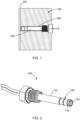
- a temperature detector probe 100 which may also be referred to as a sensor device, is operable to detect the temperature of an object 102, and more particularly, a surface 104 of the object 102.
- the object 102 may be, for example, a chuck or pedestal used for processing semiconductor wafers.
- the temperature detector probe 100 may be used to detect the temperature of other objects and should not be limited to the examples provided herein.
- the temperature detector probe 100 extends through the object 102 up to the surface 104.
- a gap 106 is provided between the temperature detector probe 100 and the object 102 to reduce thermal conductivity between the object 102 and the probe 100.
- the size of the gap can vary based on the application.
- the probe 100 includes a housing 110, one or more electrical connectors 112 (i.e.,112 1 and 112 2 ), a support cap 114, and a sensor 116.
- the housing 110 has a first end portion 120 and a second end portion 122, and defines a bore 124 that extends longitudinally through the housing 110 between the first end portion 120 and the second end portion 122.
- a cap 125 is provided at the first end portion 120 to prevent foreign matter from entering the probe 100.
- the housing 110 may be viewed as having an extension portion 130, which includes the first end portion 120, and a sensor portion 132, which includes the second end portion 122.
- the sensor portion 132 When located within the object 102, the sensor portion 132 is positioned closer to the surface 104 of the object 102 than the extension portion 130.
- the sensor portion 132 of the housing 110 includes one or more thermal breaks 134 provided as circumferential grooves defined along an exterior of the housing 110 to inhibit thermal conductivity between the object 102 and the probe 100, and between the extension portion 130 and the sensor portion 132.
- the thermal breaks 134 extend through the housing 110, and in another form, a thin wall of the housing 110 is provided between the thermal breaks 134 and the bore 124.
- the housing 110 may be made of plastic, such high-performance polyimide-based plastics, such as polyether ether ketone, or other suitable material.
- the RTD surface mount device follows an industry standard 0603 size (0.8 X 1.6 mm) for surface mount devices, and has a 0.45mm thickness and has a mass of 1.9 mg.
- the sensor 116 is a thermocouple mounted to the surface of the support cap 114.
- the sensor 116 is configured to directly contact or be in proximity to the surface 104 of the object 102 to measure a temperature of the surface 104.
- the support cap 114 has resilient or elastic qualities, such that the position of sensor 116 is flexible to contact the surface 104 of the object 102.
- the electrical connectors 112 being POGO pins, the pins provide a biasing force against the support cap 114 and the sensor 116 to have the sensor 116 contact the surface 104.
- the probe 100 is positioned in the object 102, and is electrically coupled to the control system by way of the electrical connectors 112 and wires.
- the sensor 116 may be in direct contact with or is proximity to the surface 104 to measure the temperature of the surface 104.
- the control system is communicably coupled to the sensor 116, and receives a signal that is indicative of temperature from the sensor 116.
- the thermal conductivity between probe 100 and the object and between the sensor 116 and the housing 110 is reduced or inhibited to potentially improve, for example, accuracy, response time, and offset errors of the sensor.
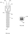
- FIGS. 4A and 4B illustrate another variation of a temperature detector probe that has different electrical connectors and sensor.
- a temperature detector probe 200 includes the housing 110, a pair of electrical pins or leads 202 (i.e., 202 1 and 202 2 ), a pair of electrical connectors 204 (i.e., 204 1 and 204 2 ), a support cap 206, and a sensor 208.
- the electrical leads 202 are operable to electrically couple the probe 200 to the control system, and extend through the first end portion 120 of the housing 110.
- the probe 200 further includes a cap 210 disposed at the first end portion 120 to prevent foreign material from entering the housing 110.
- the electrical connectors 204 are wires that are connected to the leads 202, for example, solder or spot welding, and may be referred to as wires 204.
- the electrical connectors 204 are small gauge wires, such as 36 to 40 gauge.
- the wires 204 extend through the bore 124 and are electrically coupled to the sensor 208 via the support cap 206.
- the senor 208 is a resistive element 208 having a high TCR that is deposited on the support cap 206. That is, in lieu of mounting a case having the resistive material disposed therein, the probe 200 provides the resistive material directly on the support cap 206. Accordingly, when disposed in the object, the resistive material is directly in contact with or in close proximity to the surface of the object, and thus, may increase the response time of the sensor 208 and reduce thermal shunting.
- the support cap 206 is a rigid disk of low thermal expansion material such as quartz, silicon, aluminum oxide (Al2O3), aluminum nitride (AIN).
- the support cap 206 is made of a metal substrate such as stainless steel or Invar coated with a dielectric to insulate the resistive element (i.e. sensor 208) from the substrate. Similar to the probe 100, a plated through hole may be formed in the support cap 206 to electrically couple the sensor 208 (i.e., resistive material) to the electrical connectors 204, and thus, to the control system.
- the support cap 206 could also be configured in a skeletonized structure to further reduce thermal loss between the sensor 208 and the support cap 206.
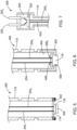
- the temperature detector probe 100, 200 may be provided with additional support for providing flexibility to the sensor and support cap. More particularly, a temperature detector probe 300 is configured in a similar manner as probe 200, but includes the sensor 116 and support cap 114 of probe 100. The probe 300 further includes a retainer ring 302 disposed at the second end portion 122 of the housing 110 and a temperature insulating material 304 (TIM) provided on the sensor 116. The retaining ring 302 secures the support cap 114 to the housing 110.
- TIM temperature insulating material
- the polymer is essentially a binder that holds this sophisticated combination of solids in usable form typically a sheet available in various thicknesses to fit the application or a dispensable liquid or paste form which may cure into a more stable soft solid material.
- TIM materials are Fujipoly, Sarcon, SPG20A, Sarcon GTR or Sarcon QR.
- the TIM 304 improves the thermal interface of the sensor 116 to the surface of the object to improve the accuracy of the temperature measurement.
- a temperature detector probe 400 provides another configuration for supporting and providing flexibility to the sensor.
- the probe 400 includes the wires (i.e., electrical connectors 204) and leads 202 of probe 200 to electrically couple the sensor 116 to the control system.
- the probe 400 includes a support cap 402 provided at the second end portion 122 of the housing 110.
- the support cap 402 is made of elastomer, and may be configured in various suitable ways to support the sensor 116.
- the support cap 402 includes a wall 404 that interfaces with an inner-wall of the housing 110, and defines a cavity 406 for housing the sensor 116 and access ports 408 (i.e., 408 1 and 408 2 ) for receiving the wires.
- the temperature detector probe of the present disclosure may also include additional circuitry to process the signal from the sensor prior to providing the signal to the control system.
- a probe 500 is configured in a similar manner as probe 200, 300, 400 and includes wires, as the electrical connectors, and leads 202.
- the probe 500 includes a signal processing circuit (SPC) 502 disposed in a chamber 504 defined within the housing 110.
- the SPC 702 is electrically coupled to the sensor (not shown) with a first set of wires 506 (i.e., 506 1 and 506 2 ), and to the leads 202 via a second set of wires 508 (i.e., 508 1 and 508 2 ).
- the wires 506 and 508 form electrical connectors that electrically couple the sensor 116 to the SPC 502, and the SPC 502 to the leads 202.
- the SPC 502 may be configured in various suitable ways to condition the original signal from the sensor 116 prior to transmitting the signal to the control system.
- the SPC 502 includes one or more electrical components to, for example, filter noise from the original signal, increase the strength of the signal, convert the signal to a particular to format utilized by the control system, convert the signal to a digital value, and/or perform a sensor offset correction.
- the probe 500 can be customized for a particular control system to provide an enhanced signal based on the original signal from the sensor.
- SPC 502 is thermally interfaced to the housing 110, and the housing 110 is thermally interfaced by direct contact such as an interference fit or through use of a TIM to the object 102.
- each of the probes 100, 200, 300, 400 and 500 may be configured to hold an insulating gas.
- the probe 400 may be filled with an insulating gas, such as Argon, to further inhibit thermal conductivity between the housing 110 and the sensor 116.
- the temperature detector probes of the present disclosure are configured to inhibit thermal conductivity between the sensor from the surrounding components, such as the housing, to improve the accuracy of the measured temperature of a surface. Additional improvements to the measurement are also provided by having the sensor interface directly with the surface being measured. The addition of a TIM to the sensor surface improves thermal interfacing and sensor repeatability with the surface being measured.
- the flexible support cap provides a constant force against the sensor, the TIM, and the surface being sensed.
Landscapes
- Physics & Mathematics (AREA)
- General Physics & Mathematics (AREA)
- Measuring Temperature Or Quantity Of Heat (AREA)
Applications Claiming Priority (2)
| Application Number | Priority Date | Filing Date | Title |
|---|---|---|---|
| US201862647094P | 2018-03-23 | 2018-03-23 | |
| PCT/US2019/023364 WO2019183353A1 (en) | 2018-03-23 | 2019-03-21 | Temperature detector probe with thermal isolation |
Publications (2)
| Publication Number | Publication Date |
|---|---|
| EP3769060A1 EP3769060A1 (en) | 2021-01-27 |
| EP3769060B1 true EP3769060B1 (en) | 2025-03-12 |
Family
ID=66041707
Family Applications (1)
| Application Number | Title | Priority Date | Filing Date |
|---|---|---|---|
| EP19715681.3A Active EP3769060B1 (en) | 2018-03-23 | 2019-03-21 | Temperature detector probe with thermal isolation |
Country Status (6)
| Country | Link |
|---|---|
| US (3) | US11280684B2 (https=) |
| EP (1) | EP3769060B1 (https=) |
| JP (1) | JP7309744B2 (https=) |
| KR (1) | KR102925276B1 (https=) |
| TW (1) | TWI709734B (https=) |
| WO (1) | WO2019183353A1 (https=) |
Families Citing this family (6)
| Publication number | Priority date | Publication date | Assignee | Title |
|---|---|---|---|---|
| DE102020103915A1 (de) * | 2020-02-14 | 2021-08-19 | Schlaeger Kunststofftechnik Gmbh | Vorrichtung zur Erfassung der Temperatur eines Objekts |
| US11583141B2 (en) | 2020-04-30 | 2023-02-21 | Weber-Stephen Products Llc | Mountable trays for temperature probe hubs |
| EP3951339B1 (en) * | 2020-08-06 | 2022-10-05 | Qnami AG | Nanoscale thermometry |
| CN111855000B (zh) * | 2020-08-21 | 2025-08-29 | 深圳市敏杰电子科技有限公司 | 防热辐射温度传感器 |
| CN114107923B (zh) * | 2021-11-02 | 2022-09-09 | 西北工业大学 | 一种金属基薄膜热流微传感器及其制备方法 |
| CN115691844A (zh) * | 2022-10-26 | 2023-02-03 | 连云港杰瑞电子有限公司 | 一种用于核电站冷却剂泄漏监测的温湿度探头 |
Citations (2)
| Publication number | Priority date | Publication date | Assignee | Title |
|---|---|---|---|---|
| JP2007300065A (ja) * | 2006-04-05 | 2007-11-15 | Mitsui Mining & Smelting Co Ltd | 薄膜センサ、薄膜センサモジュール及び薄膜センサの製造方法 |
| US7651269B2 (en) * | 2007-07-19 | 2010-01-26 | Lam Research Corporation | Temperature probes having a thermally isolated tip |
Family Cites Families (32)
| Publication number | Priority date | Publication date | Assignee | Title |
|---|---|---|---|---|
| US2588014A (en) * | 1949-04-27 | 1952-03-04 | Lewis Eng Co | Resistance thermometer bulb |
| US3151484A (en) * | 1961-02-03 | 1964-10-06 | Gulf Oil Corp | Thermocouple support |
| CH447652A (de) * | 1965-02-04 | 1967-11-30 | Ceskoslovenska Akademie Ved | Elektrischer Temperatur-Messfühler |
| JPS5127140B1 (https=) * | 1970-12-18 | 1976-08-11 | ||
| CA1040746A (en) | 1976-06-30 | 1978-10-17 | Robert W. Bertram | Thin film resistance temperature detector |
| US4242659A (en) * | 1979-10-15 | 1980-12-30 | Leeds & Northrup Company | Thin film resistance thermometer detector probe assembly |
| GB2062860A (en) * | 1979-11-06 | 1981-05-28 | Iss Clorius Ltd | Temperature sensing assembly |
| US4492948A (en) * | 1981-09-02 | 1985-01-08 | Leeds & Northrup Company | Fast response surface contact temperature sensor |
| US4454370A (en) * | 1982-09-07 | 1984-06-12 | Wahl Instruments, Inc. | Thermocouple surface probe |
| FR2580806B1 (fr) * | 1985-04-19 | 1987-06-26 | Gouault Jean | Sonde thermometrique pour la mesure de temperatures superficielles notamment cutanees |
| US4749415A (en) * | 1987-01-28 | 1988-06-07 | Westinghouse Electric Corp. | Fast response thermocouple element |
| US4962765A (en) * | 1987-03-12 | 1990-10-16 | Abiomed, Inc. | Diagnostic temperature probe |
| US5215597A (en) * | 1989-08-08 | 1993-06-01 | The United States Of America As Represented By The United States Department Of Energy | Method for bonding thin film thermocouples to ceramics |
| EP0764837A1 (en) * | 1995-09-25 | 1997-03-26 | Isuzu Ceramics Research Institute Co., Ltd. | Thermocouple structure |
| US6257758B1 (en) | 1998-10-09 | 2001-07-10 | Claud S. Gordon Company | Surface temperature sensor |
| JP2001201402A (ja) * | 2000-01-20 | 2001-07-27 | Kawaso Denki Kogyo Kk | 温度センサ及び接触式温度検出装置 |
| GB0103886D0 (en) * | 2001-02-16 | 2001-04-04 | Baumbach Per L | Temperature measuring device |
| US6821015B2 (en) * | 2002-01-25 | 2004-11-23 | Robert Hammer | Conducted heat vector sensor |
| US7473031B2 (en) | 2002-04-01 | 2009-01-06 | Palo Alto Research Center, Incorporated | Resistive thermal sensing |
| KR100464133B1 (ko) * | 2003-03-27 | 2005-01-03 | 주식회사 대양계기 | 온도센서장치 |
| US7000478B1 (en) * | 2005-01-31 | 2006-02-21 | Texas Instruments Incorporated | Combined pressure and temperature transducer |
| DE102005038466B4 (de) | 2005-08-13 | 2007-12-13 | Sitronic Gesellschaft für elektrotechnische Ausrüstung mbH. & Co. KG | Sensoranordnung zur Temperaturmessung |
| CN101038214B (zh) * | 2006-03-14 | 2010-12-01 | 美亚铝厂有限公司 | 测量温度的装置和方法 |
| EP1843138B1 (en) * | 2006-04-06 | 2012-05-16 | Sauer-Danfoss ApS | A bolt having a layer of conducting material forming a sensor |
| JP5027573B2 (ja) * | 2006-07-06 | 2012-09-19 | 株式会社小松製作所 | 温度センサおよび温調装置 |
| DE102006062115B4 (de) | 2006-12-22 | 2010-08-19 | Sitronic Ges. für elektrotechnische Ausrüstung GmbH & Co. KG | Sensoranordnung zur Temperaturmessung |
| JP2009109313A (ja) * | 2007-10-30 | 2009-05-21 | Denso Corp | 圧力温度複合センサ |
| US8118486B2 (en) * | 2008-09-04 | 2012-02-21 | AGlobal Tech, LLC | Very high speed temperature probe |
| US9341522B2 (en) * | 2013-05-01 | 2016-05-17 | Rosemount Inc. | Spring-loaded temperature sensor |
| DE202013007490U1 (de) * | 2013-08-23 | 2013-11-19 | Elth S.A. | Temperatursensor für ein Fluid |
| US9417138B2 (en) | 2013-09-10 | 2016-08-16 | Varian Semiconductor Equipment Associates, Inc. | Gas coupled probe for substrate temperature measurement |
| US10393592B2 (en) * | 2016-12-21 | 2019-08-27 | Intel Corporation | Systems and methods for measuring surface temperature |
-
2019
- 2019-03-21 EP EP19715681.3A patent/EP3769060B1/en active Active
- 2019-03-21 KR KR1020207030502A patent/KR102925276B1/ko active Active
- 2019-03-21 US US16/360,669 patent/US11280684B2/en active Active
- 2019-03-21 JP JP2020550750A patent/JP7309744B2/ja active Active
- 2019-03-21 WO PCT/US2019/023364 patent/WO2019183353A1/en not_active Ceased
- 2019-03-22 TW TW108110118A patent/TWI709734B/zh active
-
2022
- 2022-03-22 US US17/700,582 patent/US12372416B2/en active Active
-
2025
- 2025-07-28 US US19/282,660 patent/US20250354875A1/en active Pending
Patent Citations (2)
| Publication number | Priority date | Publication date | Assignee | Title |
|---|---|---|---|---|
| JP2007300065A (ja) * | 2006-04-05 | 2007-11-15 | Mitsui Mining & Smelting Co Ltd | 薄膜センサ、薄膜センサモジュール及び薄膜センサの製造方法 |
| US7651269B2 (en) * | 2007-07-19 | 2010-01-26 | Lam Research Corporation | Temperature probes having a thermally isolated tip |
Also Published As
| Publication number | Publication date |
|---|---|
| US20250354875A1 (en) | 2025-11-20 |
| WO2019183353A1 (en) | 2019-09-26 |
| JP7309744B2 (ja) | 2023-07-18 |
| JP2021518546A (ja) | 2021-08-02 |
| KR102925276B1 (ko) | 2026-02-06 |
| US20220214225A1 (en) | 2022-07-07 |
| KR20200131330A (ko) | 2020-11-23 |
| US11280684B2 (en) | 2022-03-22 |
| TW201940851A (zh) | 2019-10-16 |
| US12372416B2 (en) | 2025-07-29 |
| EP3769060A1 (en) | 2021-01-27 |
| TWI709734B (zh) | 2020-11-11 |
| US20190293495A1 (en) | 2019-09-26 |
Similar Documents
| Publication | Publication Date | Title |
|---|---|---|
| US12372416B2 (en) | Temperature detector probe with thermal isolation | |
| US11422050B2 (en) | Temperature-pressure integrated sensor with improved assembly and processing | |
| US8814428B2 (en) | Temperature sensing apparatus | |
| US20210063436A1 (en) | Socket side thermal system | |
| US11913840B2 (en) | Measuring insert having a protective tube | |
| GB2556170A (en) | Integrated pressure and temperature sensor | |
| JP2007147616A (ja) | 流体の圧力および温度を測定するセンサ装置 | |
| JP3662018B2 (ja) | 内燃機関の燃焼室内の圧力を検出するための圧力センサ | |
| US5711607A (en) | Temperature measurement technique with automatic verification of contact between probe and object | |
| US11976994B2 (en) | Sensor for detecting pressure, filling level, density, temperature, mass and/or flow rate including nanowires arranged on coupling section | |
| US12578234B2 (en) | Measuring device | |
| JP2001174351A (ja) | 圧力センサ | |
| EP3563132B1 (en) | High accuracy pressure transducer with improved temperature stability | |
| US9063020B2 (en) | Method and device for measuring temperature having a separate structure for terminal areas arranged in unrestricted thermal contact with a process liquid | |
| JPH08146026A (ja) | サーミスタ流速センサーおよび液体用流量センサー | |
| KR100347642B1 (ko) | 내연기관의연소실내의압력을검출하기위한압력변환기 | |
| JP2007234950A (ja) | 温度センサ付きヒートシンク | |
| US12372418B2 (en) | Method of shielding capacitive pressure sensor | |
| JP2001281033A (ja) | 液体用流量センサー | |
| EP2866012A1 (en) | A sensor element comprising a constraining layer | |
| CN120609486A (zh) | 一种压力传感器及压力芯体结构 |
Legal Events
| Date | Code | Title | Description |
|---|---|---|---|
| STAA | Information on the status of an ep patent application or granted ep patent |
Free format text: STATUS: UNKNOWN |
|
| STAA | Information on the status of an ep patent application or granted ep patent |
Free format text: STATUS: THE INTERNATIONAL PUBLICATION HAS BEEN MADE |
|
| PUAI | Public reference made under article 153(3) epc to a published international application that has entered the european phase |
Free format text: ORIGINAL CODE: 0009012 |
|
| STAA | Information on the status of an ep patent application or granted ep patent |
Free format text: STATUS: REQUEST FOR EXAMINATION WAS MADE |
|
| 17P | Request for examination filed |
Effective date: 20200930 |
|
| AK | Designated contracting states |
Kind code of ref document: A1 Designated state(s): AL AT BE BG CH CY CZ DE DK EE ES FI FR GB GR HR HU IE IS IT LI LT LU LV MC MK MT NL NO PL PT RO RS SE SI SK SM TR |
|
| AX | Request for extension of the european patent |
Extension state: BA ME |
|
| DAV | Request for validation of the european patent (deleted) | ||
| DAX | Request for extension of the european patent (deleted) | ||
| STAA | Information on the status of an ep patent application or granted ep patent |
Free format text: STATUS: EXAMINATION IS IN PROGRESS |
|
| 17Q | First examination report despatched |
Effective date: 20220718 |
|
| GRAJ | Information related to disapproval of communication of intention to grant by the applicant or resumption of examination proceedings by the epo deleted |
Free format text: ORIGINAL CODE: EPIDOSDIGR1 |
|
| STAA | Information on the status of an ep patent application or granted ep patent |
Free format text: STATUS: GRANT OF PATENT IS INTENDED |
|
| GRAP | Despatch of communication of intention to grant a patent |
Free format text: ORIGINAL CODE: EPIDOSNIGR1 |
|
| INTG | Intention to grant announced |
Effective date: 20240522 |
|
| GRAJ | Information related to disapproval of communication of intention to grant by the applicant or resumption of examination proceedings by the epo deleted |
Free format text: ORIGINAL CODE: EPIDOSDIGR1 |
|
| STAA | Information on the status of an ep patent application or granted ep patent |
Free format text: STATUS: EXAMINATION IS IN PROGRESS |
|
| GRAP | Despatch of communication of intention to grant a patent |
Free format text: ORIGINAL CODE: EPIDOSNIGR1 |
|
| STAA | Information on the status of an ep patent application or granted ep patent |
Free format text: STATUS: GRANT OF PATENT IS INTENDED |
|
| INTC | Intention to grant announced (deleted) | ||
| INTG | Intention to grant announced |
Effective date: 20241002 |
|
| GRAS | Grant fee paid |
Free format text: ORIGINAL CODE: EPIDOSNIGR3 |
|
| GRAA | (expected) grant |
Free format text: ORIGINAL CODE: 0009210 |
|
| STAA | Information on the status of an ep patent application or granted ep patent |
Free format text: STATUS: THE PATENT HAS BEEN GRANTED |
|
| AK | Designated contracting states |
Kind code of ref document: B1 Designated state(s): AL AT BE BG CH CY CZ DE DK EE ES FI FR GB GR HR HU IE IS IT LI LT LU LV MC MK MT NL NO PL PT RO RS SE SI SK SM TR |
|
| REG | Reference to a national code |
Ref country code: GB Ref legal event code: FG4D |
|
| REG | Reference to a national code |
Ref country code: CH Ref legal event code: EP |
|
| REG | Reference to a national code |
Ref country code: DE Ref legal event code: R096 Ref document number: 602019067154 Country of ref document: DE |
|
| REG | Reference to a national code |
Ref country code: IE Ref legal event code: FG4D |
|
| PG25 | Lapsed in a contracting state [announced via postgrant information from national office to epo] |
Ref country code: RS Free format text: LAPSE BECAUSE OF FAILURE TO SUBMIT A TRANSLATION OF THE DESCRIPTION OR TO PAY THE FEE WITHIN THE PRESCRIBED TIME-LIMIT Effective date: 20250612 |
|
| PG25 | Lapsed in a contracting state [announced via postgrant information from national office to epo] |
Ref country code: FI Free format text: LAPSE BECAUSE OF FAILURE TO SUBMIT A TRANSLATION OF THE DESCRIPTION OR TO PAY THE FEE WITHIN THE PRESCRIBED TIME-LIMIT Effective date: 20250312 |
|
| PG25 | Lapsed in a contracting state [announced via postgrant information from national office to epo] |
Ref country code: ES Free format text: LAPSE BECAUSE OF FAILURE TO SUBMIT A TRANSLATION OF THE DESCRIPTION OR TO PAY THE FEE WITHIN THE PRESCRIBED TIME-LIMIT Effective date: 20250312 |
|
| REG | Reference to a national code |
Ref country code: LT Ref legal event code: MG9D |
|
| PG25 | Lapsed in a contracting state [announced via postgrant information from national office to epo] |
Ref country code: NO Free format text: LAPSE BECAUSE OF FAILURE TO SUBMIT A TRANSLATION OF THE DESCRIPTION OR TO PAY THE FEE WITHIN THE PRESCRIBED TIME-LIMIT Effective date: 20250612 |
|
| PG25 | Lapsed in a contracting state [announced via postgrant information from national office to epo] |
Ref country code: HR Free format text: LAPSE BECAUSE OF FAILURE TO SUBMIT A TRANSLATION OF THE DESCRIPTION OR TO PAY THE FEE WITHIN THE PRESCRIBED TIME-LIMIT Effective date: 20250312 |
|
| REG | Reference to a national code |
Ref country code: NL Ref legal event code: MP Effective date: 20250312 |
|
| PG25 | Lapsed in a contracting state [announced via postgrant information from national office to epo] |
Ref country code: LV Free format text: LAPSE BECAUSE OF FAILURE TO SUBMIT A TRANSLATION OF THE DESCRIPTION OR TO PAY THE FEE WITHIN THE PRESCRIBED TIME-LIMIT Effective date: 20250312 |
|
| PG25 | Lapsed in a contracting state [announced via postgrant information from national office to epo] |
Ref country code: BG Free format text: LAPSE BECAUSE OF FAILURE TO SUBMIT A TRANSLATION OF THE DESCRIPTION OR TO PAY THE FEE WITHIN THE PRESCRIBED TIME-LIMIT Effective date: 20250312 Ref country code: GR Free format text: LAPSE BECAUSE OF FAILURE TO SUBMIT A TRANSLATION OF THE DESCRIPTION OR TO PAY THE FEE WITHIN THE PRESCRIBED TIME-LIMIT Effective date: 20250613 |
|
| REG | Reference to a national code |
Ref country code: AT Ref legal event code: MK05 Ref document number: 1775349 Country of ref document: AT Kind code of ref document: T Effective date: 20250312 |
|
| PG25 | Lapsed in a contracting state [announced via postgrant information from national office to epo] |
Ref country code: NL Free format text: LAPSE BECAUSE OF FAILURE TO SUBMIT A TRANSLATION OF THE DESCRIPTION OR TO PAY THE FEE WITHIN THE PRESCRIBED TIME-LIMIT Effective date: 20250312 |
|
| PG25 | Lapsed in a contracting state [announced via postgrant information from national office to epo] |
Ref country code: SE Free format text: LAPSE BECAUSE OF FAILURE TO SUBMIT A TRANSLATION OF THE DESCRIPTION OR TO PAY THE FEE WITHIN THE PRESCRIBED TIME-LIMIT Effective date: 20250312 |
|
| PG25 | Lapsed in a contracting state [announced via postgrant information from national office to epo] |
Ref country code: SM Free format text: LAPSE BECAUSE OF FAILURE TO SUBMIT A TRANSLATION OF THE DESCRIPTION OR TO PAY THE FEE WITHIN THE PRESCRIBED TIME-LIMIT Effective date: 20250312 |
|
| PG25 | Lapsed in a contracting state [announced via postgrant information from national office to epo] |
Ref country code: PT Free format text: LAPSE BECAUSE OF FAILURE TO SUBMIT A TRANSLATION OF THE DESCRIPTION OR TO PAY THE FEE WITHIN THE PRESCRIBED TIME-LIMIT Effective date: 20250714 |
|
| PG25 | Lapsed in a contracting state [announced via postgrant information from national office to epo] |
Ref country code: IT Free format text: LAPSE BECAUSE OF FAILURE TO SUBMIT A TRANSLATION OF THE DESCRIPTION OR TO PAY THE FEE WITHIN THE PRESCRIBED TIME-LIMIT Effective date: 20250312 Ref country code: PL Free format text: LAPSE BECAUSE OF FAILURE TO SUBMIT A TRANSLATION OF THE DESCRIPTION OR TO PAY THE FEE WITHIN THE PRESCRIBED TIME-LIMIT Effective date: 20250312 |
|
| PG25 | Lapsed in a contracting state [announced via postgrant information from national office to epo] |
Ref country code: AT Free format text: LAPSE BECAUSE OF FAILURE TO SUBMIT A TRANSLATION OF THE DESCRIPTION OR TO PAY THE FEE WITHIN THE PRESCRIBED TIME-LIMIT Effective date: 20250312 |
|
| PG25 | Lapsed in a contracting state [announced via postgrant information from national office to epo] |
Ref country code: CZ Free format text: LAPSE BECAUSE OF FAILURE TO SUBMIT A TRANSLATION OF THE DESCRIPTION OR TO PAY THE FEE WITHIN THE PRESCRIBED TIME-LIMIT Effective date: 20250312 Ref country code: EE Free format text: LAPSE BECAUSE OF FAILURE TO SUBMIT A TRANSLATION OF THE DESCRIPTION OR TO PAY THE FEE WITHIN THE PRESCRIBED TIME-LIMIT Effective date: 20250312 |
|
| REG | Reference to a national code |
Ref country code: CH Ref legal event code: H13 Free format text: ST27 STATUS EVENT CODE: U-0-0-H10-H13 (AS PROVIDED BY THE NATIONAL OFFICE) Effective date: 20251023 |
|
| PG25 | Lapsed in a contracting state [announced via postgrant information from national office to epo] |
Ref country code: RO Free format text: LAPSE BECAUSE OF FAILURE TO SUBMIT A TRANSLATION OF THE DESCRIPTION OR TO PAY THE FEE WITHIN THE PRESCRIBED TIME-LIMIT Effective date: 20250312 |
|
| PG25 | Lapsed in a contracting state [announced via postgrant information from national office to epo] |
Ref country code: SK Free format text: LAPSE BECAUSE OF FAILURE TO SUBMIT A TRANSLATION OF THE DESCRIPTION OR TO PAY THE FEE WITHIN THE PRESCRIBED TIME-LIMIT Effective date: 20250312 |
|
| PG25 | Lapsed in a contracting state [announced via postgrant information from national office to epo] |
Ref country code: IS Free format text: LAPSE BECAUSE OF FAILURE TO SUBMIT A TRANSLATION OF THE DESCRIPTION OR TO PAY THE FEE WITHIN THE PRESCRIBED TIME-LIMIT Effective date: 20250712 |
|
| PG25 | Lapsed in a contracting state [announced via postgrant information from national office to epo] |
Ref country code: LU Free format text: LAPSE BECAUSE OF NON-PAYMENT OF DUE FEES Effective date: 20250321 |
|
| REG | Reference to a national code |
Ref country code: BE Ref legal event code: MM Effective date: 20250331 |
|
| REG | Reference to a national code |
Ref country code: DE Ref legal event code: R097 Ref document number: 602019067154 Country of ref document: DE |
|
| PG25 | Lapsed in a contracting state [announced via postgrant information from national office to epo] |
Ref country code: MC Free format text: LAPSE BECAUSE OF FAILURE TO SUBMIT A TRANSLATION OF THE DESCRIPTION OR TO PAY THE FEE WITHIN THE PRESCRIBED TIME-LIMIT Effective date: 20250312 |
|
| PG25 | Lapsed in a contracting state [announced via postgrant information from national office to epo] |
Ref country code: DK Free format text: LAPSE BECAUSE OF FAILURE TO SUBMIT A TRANSLATION OF THE DESCRIPTION OR TO PAY THE FEE WITHIN THE PRESCRIBED TIME-LIMIT Effective date: 20250312 |
|
| PG25 | Lapsed in a contracting state [announced via postgrant information from national office to epo] |
Ref country code: BE Free format text: LAPSE BECAUSE OF NON-PAYMENT OF DUE FEES Effective date: 20250331 |
|
| PLBE | No opposition filed within time limit |
Free format text: ORIGINAL CODE: 0009261 |
|
| STAA | Information on the status of an ep patent application or granted ep patent |
Free format text: STATUS: NO OPPOSITION FILED WITHIN TIME LIMIT |
|
| PG25 | Lapsed in a contracting state [announced via postgrant information from national office to epo] |
Ref country code: CH Free format text: LAPSE BECAUSE OF NON-PAYMENT OF DUE FEES Effective date: 20250331 |
|
| PG25 | Lapsed in a contracting state [announced via postgrant information from national office to epo] |
Ref country code: IE Free format text: LAPSE BECAUSE OF NON-PAYMENT OF DUE FEES Effective date: 20250321 |
|
| REG | Reference to a national code |
Ref country code: CH Ref legal event code: L10 Free format text: ST27 STATUS EVENT CODE: U-0-0-L10-L00 (AS PROVIDED BY THE NATIONAL OFFICE) Effective date: 20260121 |
|
| 26N | No opposition filed |
Effective date: 20251215 |
|
| GBPC | Gb: european patent ceased through non-payment of renewal fee |
Effective date: 20250612 |
|
| PG25 | Lapsed in a contracting state [announced via postgrant information from national office to epo] |
Ref country code: GB Free format text: LAPSE BECAUSE OF NON-PAYMENT OF DUE FEES Effective date: 20250612 |
|
| PGFP | Annual fee paid to national office [announced via postgrant information from national office to epo] |
Ref country code: DE Payment date: 20260327 Year of fee payment: 8 |
|
| PGFP | Annual fee paid to national office [announced via postgrant information from national office to epo] |
Ref country code: FR Payment date: 20260325 Year of fee payment: 8 |