EP3769002B1 - Conduit de fluides chauffé comprenant une partie de blocage - Google Patents
Conduit de fluides chauffé comprenant une partie de blocage Download PDFInfo
- Publication number
- EP3769002B1 EP3769002B1 EP19714356.3A EP19714356A EP3769002B1 EP 3769002 B1 EP3769002 B1 EP 3769002B1 EP 19714356 A EP19714356 A EP 19714356A EP 3769002 B1 EP3769002 B1 EP 3769002B1
- Authority
- EP
- European Patent Office
- Prior art keywords
- pipe
- hose line
- line
- encapsulation
- fixing part
- Prior art date
- Legal status (The legal status is an assumption and is not a legal conclusion. Google has not performed a legal analysis and makes no representation as to the accuracy of the status listed.)
- Active
Links
- 238000010438 heat treatment Methods 0.000 claims description 37
- 238000005538 encapsulation Methods 0.000 claims description 35
- 239000004020 conductor Substances 0.000 claims description 33
- 238000004804 winding Methods 0.000 claims description 17
- 238000006073 displacement reaction Methods 0.000 claims description 4
- 239000002991 molded plastic Substances 0.000 claims 1
- 238000011144 upstream manufacturing Methods 0.000 claims 1
- 229920003023 plastic Polymers 0.000 description 8
- 238000003466 welding Methods 0.000 description 8
- XLYOFNOQVPJJNP-UHFFFAOYSA-N water Substances O XLYOFNOQVPJJNP-UHFFFAOYSA-N 0.000 description 7
- 238000013461 design Methods 0.000 description 6
- 238000002347 injection Methods 0.000 description 5
- 239000007924 injection Substances 0.000 description 5
- 238000012549 training Methods 0.000 description 5
- 239000002775 capsule Substances 0.000 description 4
- 238000002485 combustion reaction Methods 0.000 description 4
- 238000000034 method Methods 0.000 description 4
- 239000012530 fluid Substances 0.000 description 3
- MWUXSHHQAYIFBG-UHFFFAOYSA-N nitrogen oxide Inorganic materials O=[N] MWUXSHHQAYIFBG-UHFFFAOYSA-N 0.000 description 3
- 230000015572 biosynthetic process Effects 0.000 description 2
- 239000000446 fuel Substances 0.000 description 2
- 239000007789 gas Substances 0.000 description 2
- 239000000463 material Substances 0.000 description 2
- 238000012986 modification Methods 0.000 description 2
- 230000004048 modification Effects 0.000 description 2
- 230000002093 peripheral effect Effects 0.000 description 2
- 238000001816 cooling Methods 0.000 description 1
- 230000008878 coupling Effects 0.000 description 1
- 238000010168 coupling process Methods 0.000 description 1
- 238000005859 coupling reaction Methods 0.000 description 1
- 238000002788 crimping Methods 0.000 description 1
- 238000005520 cutting process Methods 0.000 description 1
- 239000012153 distilled water Substances 0.000 description 1
- 238000009826 distribution Methods 0.000 description 1
- 230000000694 effects Effects 0.000 description 1
- 230000008020 evaporation Effects 0.000 description 1
- 238000001704 evaporation Methods 0.000 description 1
- 230000003203 everyday effect Effects 0.000 description 1
- 238000007710 freezing Methods 0.000 description 1
- 230000008014 freezing Effects 0.000 description 1
- 238000003780 insertion Methods 0.000 description 1
- 230000037431 insertion Effects 0.000 description 1
- 239000003595 mist Substances 0.000 description 1
- 238000013021 overheating Methods 0.000 description 1
- 229920006300 shrink film Polymers 0.000 description 1
- 239000000243 solution Substances 0.000 description 1
- 239000012780 transparent material Substances 0.000 description 1
Images


Classifications
-
- F—MECHANICAL ENGINEERING; LIGHTING; HEATING; WEAPONS; BLASTING
- F16—ENGINEERING ELEMENTS AND UNITS; GENERAL MEASURES FOR PRODUCING AND MAINTAINING EFFECTIVE FUNCTIONING OF MACHINES OR INSTALLATIONS; THERMAL INSULATION IN GENERAL
- F16L—PIPES; JOINTS OR FITTINGS FOR PIPES; SUPPORTS FOR PIPES, CABLES OR PROTECTIVE TUBING; MEANS FOR THERMAL INSULATION IN GENERAL
- F16L53/00—Heating of pipes or pipe systems; Cooling of pipes or pipe systems
- F16L53/30—Heating of pipes or pipe systems
- F16L53/35—Ohmic-resistance heating
- F16L53/38—Ohmic-resistance heating using elongate electric heating elements, e.g. wires or ribbons
Definitions
- the invention relates to a heated media line according to the preamble of claim 1.
- heated media lines are, for example DE102013000588A1 or EP112581 0A1 known.
- Modern combustion engines are supposed to deliver high performance with efficient use of fuel and good exhaust emissions.
- the well-known water injection is used and developed further.
- a fine mist of distilled water is injected either into the intake tract and/or directly into the combustion chamber.
- the evaporation energy ensures effective cooling of the charge air or the combustion chamber and better filling in the combustion chamber. This method can help both increase performance and save fuel.
- motor vehicles that are used every day and may travel long distances, it is necessary to carry a certain amount of water for water injection.
- the invention is based on the object of providing a media line which ensures optimal function of water injection in the usual temperature range, i.e. H. at outside temperatures below 0 °C or above 0 °C, and in which the heating conductor surrounding the media line is secured in its position.
- the invention is based on the knowledge that at temperatures of 0 °C and below, heating the water-carrying pipe prevents freezing is and close to the engine area, in which the temperatures quickly rise above 0 ° C and water injection is often not necessary when the engine is cold, the water-carrying line is not heated, so that the water-carrying hose line or media line can only be heated over a partial length according to the invention.
- this allows the media line to be manufactured more cost-effectively, since only a partial wrapping with a heating conductor is required, and on the other hand, electrical energy can also be saved.
- the fixing part according to the invention ensures that the winding end present on the hose line is fixed in its position in the axial direction and circumferentially with respect to the hose line. This means that the unheated area of the hose line close to the engine can also be adjusted precisely. According to the invention, damage to the heating conductors is avoided by the axial and rotational fixing of the heating conductors by means of the fixing part.
- fluid coupling systems can be dispensed with, because the fixing part is advantageously fixed on the uninterrupted media-carrying hose line, so that there are no connection points.
- the fixing part can also be designed in such a way that two separate hose lines are connected to one another within the fixing part.
- the fixing part is enclosed by an encapsulation, so that the end region of the heating conductor located within the encapsulation and the electrical connectors that may be required can be mechanically protected and/or thermally shielded by the encapsulation.
- the encapsulation can advantageously be fixed to the fixing part ensures that the encapsulation cannot slip or twist axially. This ensures that the electrical connectors, in particular crimp connectors, provided for connecting the heating conductor ends ending within the encapsulation protected against constant movement. It is particularly advantageous if a casing tube surrounding the electrically heated hose line ends within the encapsulation.
- the encapsulation is formed by a housing which is expediently formed from two latched and/or welded half-shells and is made from a suitable plastic.
- the encapsulation can also consist of a tube that shrinks, for example when exposed to heat.
- shrink tubes are well known.
- the fixing part can also have form-fitting elements for fixing the shrunken tube; it is particularly advantageous if the fixing part is designed in such a way that the shrunken tube can fit well or that rounded contact sections are present.
- the shrunken tube In the area of the casing tube emerging from the encapsulation, which is designed in particular as a corrugated tube, the shrunken tube can lie in a form-fitting manner around the existing mountains and valleys of the corrugated tube, which is preferably used.
- an electrical connector present within the shrink tube is fixed at a certain distance from the hose line by a crimping device, so that certain radii of the heating conductors connected by the electrical connector can be maintained.
- a deflection extension can be formed on the fixing part and a continuous heating conductor can be used to heat the hose line, with the deflection point of the heating conductor being simultaneously fixed in position by the formation of the deflection extension on the fixing part.
- the encapsulation surrounding the winding end is included in the function of the fixing part. This not only affects the end of the winding Not only is the position fixed in relation to the hose line, but also the encapsulation, so that an overall optimal heating effect and heat distribution is achieved.
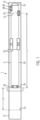
- FIG. 1 A first embodiment of a heated media line is shown.
- This media line comprises a pipe or hose line 1, which is preferably made of plastic and is designed to be flexible.
- This pipe or hose line 1 has an inner flow channel, not shown, in which a fluid, for example water, can be transported.
- a heating device 2a is arranged running in the longitudinal direction.
- This heating device 2a consists of at least one electrical heating conductor 2, which has an electrical resistance R3.
- This electrical heating conductor 2 is preferably wound spirally around the circumference of the pipe or hose line 1.
- This heating conductor 2 is applied, starting from a first connection end 1a of the pipe or hose line 1, for example for connecting a unit or another media line by means of a connection connector 2c, only over a partial length L1 of the pipe or hose line 1, for example wound in a spiral shape, so that one is not included
- the heating conductor 2 provided section of the length L2 of the pipe or hose line 1 is formed in the area in front of a winding end 2d of the heating conductor 2 with a second connection section 2e for a connection connector 2f.
- FIG. 1 is a second electrical heating conductor 2a, starting from the winding end 2d of the heating conductor 2 over the same partial length L1 to the connection end 2b, preferably wound back in a spiral shape parallel to the heating conductor 2.
- This heating conductor 2a has the resistance R3a.
- the two heating conductors 2, 2a are connected to one another at their ends by means of an electrical connector 2h, for example a crimp connector.
- the winding end 2d of the heating conductors 2, 2a is in the flow direction of the fluid flowing in the pipe or hose line 1 behind the connection end 2b and in front of the second connection end 2e of the hose line 1 for connecting a connection connector 2f for connecting to a unit or the like or another Pipe or hose line arranged.
- the hose line 1 is preferably enclosed by a fixing element 5, for example a tape or a shrink film, which is used in particular to fix the heating conductors 2, 3.
- the pipe or hose line 1 runs within a jacket pipe 6, which is designed in particular as a corrugated pipe.
- This casing tube 6 represents external mechanical and/or thermal protection and ends in front of the winding end 4.
- the casing tube 6 is made of plastic, for example.
- the winding end 4 and the casing tube 6 with its end section 6a and the electrical connector 4a are contained in an encapsulation 7 or are enclosed by this encapsulation 7.
- This encapsulation 7 can be made of plastic, for example, and also serves for thermal and/or mechanical protection.
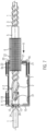
- a fixing part 8 which is seen directly on the hose line 1 in the longitudinal direction X, that is to say in Viewing direction seen from the end section 6a of the casing tube 6, behind the winding end 4, corresponding to the winding end 2d in Fig. 1 , is fastened in such a way that it is secured in the axial direction of the hose line 1 against displacement and in the circumferential direction against rotation and thus against a change in position with respect to the hose line 1.
- the fixing part 8 is advantageously fixed on the hose line 1 in a materially bonded manner, in particular by laser welding.
- the fixing part 8 is at least partially made of a laser-transparent plastic material.
- the pipe or hose line 1 expediently consists of a plastic material.
- the hose or pipeline 1 is advantageously designed to be flexible.
- the fixing part 8 is expediently made as a tubular molded part, in particular made of plastic. It consists in particular of two half-shells 9, which can be connected to one another via a snap connection. When the half-shells 9 are connected, the fixing part 8 encloses the hose line 1.
- the fixing part 8 expediently consists of an annular collar 10 and at least one guide connector 11 formed on it, the hose line 1 advantageously running centrally through the annular collar 10 and the guide connector 11.
- the guide stub 11 extends in particular from the annular collar 10 against the longitudinal direction
- each of the two half-shells 9 has two axially spaced and 180 ° offset from each other locking hooks 13, which snap into corresponding locking recesses 14 of the other half-shell 9 in the assembled state of the two half-shells 9.
- the encapsulation 7 is formed in particular from two axially spaced end walls 15, 16, each of which has a peripheral wall 18 at its end limit closed capsule space 19.
- An opening 20 is formed in the end wall 16, through which the jacket tube 6 runs, and with its opening edge 21 it is positively guided axially and circumferentially within wave troughs 22 of the jacket tube 6, which is designed, for example, as a corrugated tube.
- the opening edge 21 expediently has two radially inwardly pointing, parallel, axially spaced circumferential ribs 23, each of which engages in a wave trough 22.
- the other end wall 15 has an opening 24, which engages with its opening edge 26 in the circumferential recess 12 of the annular collar 10 and is fixed here in a form-fitting manner in the axial and circumferential direction.
- the encapsulation 7 consists of two half-shells 28, 28a, which are connected to one another in a form-fitting and force-fitting manner, in particular by a snap connection.
- opposing radial projections 29 are formed in the area of the circumferential recess 12 of the annular collar 10 of the fixing part 8. These projections 29 protrude into corresponding cutouts 30 of the end wall 15 running within the circumferential recesses 12 of the ring collar 10, so that a circumferential fixation of the encapsulation 7 on the fixing part 8 is achieved.
- the electrical connector 4a is fixed in a form-fitting manner within an inner housing 27.
- the encapsulation 7 and the fixing part 8 work together in such a way that the winding end 4 in the axial direction and in the radial direction as well as in the circumferential direction indirectly with respect to the hose or pipeline 1 is fixed in position on this in the axial and circumferential direction.
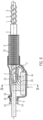
- FIG. 6 is a variation of Fig. 1a shown.
- the fixing part 8 is designed in such a way that a guide connector 11, 11a is formed on both sides of the ring collar 10.
- the hose line 1 ends in the guide connector 11 located in the encapsulation 7 and is connected to it in a materially bonded manner, in particular by laser welding.
- Another guide connector 11a running outside the encapsulation 7 has another pipe or hose line 1a inserted at its end and connected to the guide connector 11a in a materially bonded manner, in particular by laser welding.
- two separate pipe or hose lines 1, 1a are connected to one another via the fixing part 8, with the hose line 1a being the partial length L2 that is not provided with a heating conductor, see Fig. 1a , represents.
- a continuous hose line 1 is available.
- the fixing part 8 can advantageously be designed as a one-piece, integral injection molded part, for example made of plastic.
- Fig. 1a Reference is made, so that the training is in accordance with Fig. 6 with the training in accordance Fig. 1a matches.
- the two guide connectors 11, 11a consist at least partially of a laser-transparent material.
- Fig. 7 is also a modification compared to Fig. 1a shown.
- an outwardly projecting deflection extension 31 is arranged on the guide connector 11 of the fixing part 8 running in the encapsulation 7, and is advantageously formed on it.
- the inner housing 27 for receiving the electrical connector 4a is omitted.
- the embodiment is correct Fig. 7 with the execution according to Fig. 1a agree.
- FIG. 8 Another version is shown. This can determine the structure of the hose or pipe 1, the heating conductor 2, 3, etc Winding end 4 and the electrical connector 4a, the fixing element 5 and the casing tube 6 to the training according to Fig. 1a to get expelled.
- the design of the fixing part 8 and the encapsulation 7 is different.
- the fixing part 8 has a diabolo-shaped support body 32 when viewed in longitudinal section, so that it has an inwardly concave, circumferential surface.
- This support body 32 is cohesively connected to the hose line 1 running through it, in particular by laser welding.
- the support body 32 consists in particular of two half-shells, which are positively connected to one another via a snap connection, so that the support body 32 can be mounted on the hose line 1.
- the encapsulation 7 is formed by a shrink tube 33, which can be shrunk by heat and which is dimensioned such that it encloses the casing tube 6 at one end and at least partially the support body 32 at its opposite end.
- the shrink tube 33 is included the casing tube 6 is positively connected by engaging in the wave troughs 22 of the casing tube 6.
- the shrink tube 33 is also fixed in a form-fitting manner by the pointed body ends 34 formed at the ends of the concavely curved surface of the support body 32.
- the winding end 4 and the electrical connector 4a are located within the shrink tube 33.
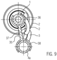
- the electrical connector 4a is expediently fixed on the hose or pipeline 1 by means of a clip device 35, see Fig. 9 .
- This clip device 35 is preferably formed from a first, C-shaped in cross-section, the hose line 1 with a wrap angle > 180 ° surrounding, radially elastic clip part 36, which is connected via a connecting web 37 to a second, C-shaped in cross-section electrical connector 4a is connected to a radially elastic clip part 38 comprising a wrap angle > 180 °.
- the clip device 35 can be clipped onto both the hose line 1 and the electrical connector 4a in a force-fitting manner, so that the electrical connector 4a can be positioned within the shrink tube 33, and after the shrinking process the electrical connector 4a is then through the adjustment of the shrink tube 33 fixed in position to the enclosed encapsulation by the heat-initiated shrinking process.
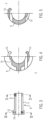
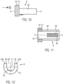
- This fixing part 8 has a guide section 40 which is U-shaped in cross section perpendicular to its longitudinal axis XX and which extends in the longitudinal direction of an inserted hose line. At one end, the guide section 40 has a holding flange 41 enclosing the guide section 40. This holding flange 41 has a receiving groove 42 in its outer peripheral surface.
- the U-shaped guide section 40 is dimensioned such that the inserted hose line 1 rests on its inner surface over a partial circumference, in particular over a circumferential angle of 180 °.
- the fixing part 8 is cohesively connected to the hose line 1 in the mutual contact area at least in a partial section, in particular by ultrasonic welding.
- the holding flange 41 which is also U-shaped in cross section to the longitudinal axis
- These end sections 44a, 44b run parallel to one another, and their mutual distance is equal to the outer diameter of the hose line 1 when the fixing part 8 is mounted on the hose line 1.
- the end sections 44a, 44b have insertion bevels 45, so that the hose line 1 is unhindered can be inserted between the end sections 44a, 44b and into the guide section 40.
- the guide section 40 is advantageously semicircular in cross section and its inner diameter and the distance between the end sections 44a, 44b are in particular the same size as the outer diameter of the hose line 1.
- the guide section 40 expediently has at least one, preferably two, on its contact surface outside the contact area Longitudinal ribs 46. In the area of these longitudinal ribs 46, the cohesive connection is expediently carried out by ultrasonic welding.
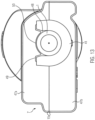
- FIG 13 is a view according to arrow direction XIII in Fig. 1a shown, but using the fixing part 8 according to the invention according to Figures 10 to 12 .
- the encapsulation 7 consists of the two half-shells 47a, 47b, which essentially correspond to the design of the half-shells 28, 28a, particularly with regard to their design in the capsule interior Fig. 1a corresponds. This also applies to the formation of the end wall 16 in Figure 1a , through which the casing tube 16 runs.
- the other end wall 15 opposite it, through which the hose line 1 emerges, has a modification to the training according to Fig. 1a an opening 48.
- the lower half-shell 47b engages with its edge in the area of the opening 48 in the receiving groove 42 of the holding flange 41.
- the opposite half-shell 47a engages in the receiving groove 42 in the area of the end sections 44a, 44b.
- a flange opening 49 located between the end sections 44a, 44b is closed by an end wall section 50, the edge of which is adapted to the circumference of the hose line 1.
- the two half-shells 47a, 47b can expediently be connected by ultrasonic welding.
Claims (7)
- Conduite de milieux chauffée comprenant une conduite ou tuyau (1) pourvue d'une lumière d'écoulement intérieure et d'au moins un conducteur chauffant électrique (2), notamment enroulé en spirale, qui s'étende sur la périphérie de la conduit rigide ou souple (1), le conducteur chauffant électrique (2) s'étendant sur une partie (L1) de la longueur de la conduite ou tuyau (1) à partir d'une première extrémité de raccordement (1a) de la conduite ou tuyau (1) jusqu'à une extrémité d'enroulement (2d, 4) du conducteur chauffant (2) de telle sorte qu'au moins une portion non pourvue du conducteur chauffant (2) soit formée avec une partie (L2) de la longueur de la conduite ou tuyau (1) avant une deuxième portion de raccordement (2e), une pièce de fixation (8) étant fixée sur la conduite ou tuyau (1) en s'opposant directement à un coulissement axial sur la conduite ou tuyau (1) et, dans sa direction périphérique, à un coulissement ou une rotation de sorte que l'extrémité d'enroulement (2d, 4) soit fixée indirectement par le biais de la pièce de fixation (8) sur la conduite ou tuyau (1) dans la direction axiale de la conduite ou tuyau (1) et, dans sa direction périphérique, en s'opposant à un coulissement ou une rotation et donc à un changement de position par rapport à la conduite ou tuyau (1),
caractérisée en ce que
la pièce de fixation (8) est une pièce moulée en matière synthétique et comporte une portion de guidage (40) qui est en forme de U perpendiculairement à son axe longitudinal (X-X) en coupe transversale, qui s'étend dans la direction longitudinale et sur laquelle, à une extrémité de la portion de guidage (40), est formée une bride de retenue (41) qui contient ladite portion de guidage, qui comporte une rainure de réception (42) dans sa surface périphérique extérieure, et la portion de guidage (40) en forme de U est dimensionnée de telle sorte que la conduite ou tuyau (1) soit en appui sur sa surface intérieure sur une partie de la périphérie de la portion de guidage (40), et la pièce de fixation (8) et la conduite ou tuyau (1) sont reliées partiellement par une liaison de matière dans la zone d'appui (43). - Conduite de milieux chauffée selon la revendication 1,
caractérisée en ce que la conduite ou tuyau (1) vient en appui sur la surface intérieure de la portion de guidage (40) en formant un angle périphérique de 180°. - Conduite de milieux chauffée selon la revendication 1 ou 2,
caractérisée en ce que la bride de retenue (41) a une forme de U en coupe transversale et comporte, dans le prolongement de sa surface d'appui (43) qui s'étend sur un angle périphérique de 180°, des portions d'extrémité (44a, 44b) qui s'étendent en parallèle à chaque extrémité et dont l'espacement correspond au moins au diamètre de la conduite ou tuyau (1). - Conduite de milieux chauffée selon l'une des revendications 1 à 3,
caractérisée en ce que la liaison de matière est une liaison soudée par ultrasons. - Conduite de milieux chauffée selon l'une des revendications 1 à 4,
caractérisée en ce qu'au moins une nervure longitudinale (46) qui s'étend dans la direction longitudinale est formée dans la zone d'appui de la surface intérieure de la portion de guidage (40). - Conduite de milieux chauffée selon l'une des revendications 1 à 5,
caractérisée en ce qu'une demi-coque (47a, 47b) d'une encapsulation (7), en particulier la demi-coque (47b) de l'encapsulation (7), s'engage dans la rainure de réception (42) au niveau des portions d'extrémité (44a, 44b) et une ouverture de bride (49), située entre les portions d'extrémité (44a, 44b), est fermée par une portion de paroi frontale (50) de la demi-coque (47a), dont le bord est adapté, dans son tracé, à la périphérie de la conduite ou tuyau (1). - Conduite de milieux chauffée selon la revendication 6,
caractérisée en ce qu'une paroi périphérique (18) de l'encapsulation (7) comporte un boîtier intérieur (27) destiné à recevoir un connecteur électrique (4a) destiné à relier les extrémités de deux conducteurs chauffants (2, 3) s'étendant sur la conduite ou tuyau (1) et comporte éventuellement des lignes d'alimentation électrique insérées dans l'encapsulation (7) et destinées à être raccordées à une source de tension électrique.
Applications Claiming Priority (3)
| Application Number | Priority Date | Filing Date | Title |
|---|---|---|---|
| DE102018107004.7A DE102018107004A1 (de) | 2018-03-23 | 2018-03-23 | Beheizte Medienleitung mit Fixierteil |
| DE102018107005.5A DE102018107005A1 (de) | 2018-03-23 | 2018-03-23 | Beheizte Medienleitung |
| PCT/EP2019/057302 WO2019180234A1 (fr) | 2018-03-23 | 2019-03-22 | Conduit de fluides chauffé comprenant une partie de blocage |
Publications (2)
| Publication Number | Publication Date |
|---|---|
| EP3769002A1 EP3769002A1 (fr) | 2021-01-27 |
| EP3769002B1 true EP3769002B1 (fr) | 2023-11-15 |
Family
ID=65991779
Family Applications (1)
| Application Number | Title | Priority Date | Filing Date |
|---|---|---|---|
| EP19714356.3A Active EP3769002B1 (fr) | 2018-03-23 | 2019-03-22 | Conduit de fluides chauffé comprenant une partie de blocage |
Country Status (2)
| Country | Link |
|---|---|
| EP (1) | EP3769002B1 (fr) |
| WO (1) | WO2019180234A1 (fr) |
Families Citing this family (1)
| Publication number | Priority date | Publication date | Assignee | Title |
|---|---|---|---|---|
| EP3575655B2 (fr) | 2018-05-29 | 2023-06-14 | TI Automotive (Fuldabrück) GmbH | Groupe de fixation de conduite et procédé de fixation d'une conduite à un clip de fixation |
Family Cites Families (5)
| Publication number | Priority date | Publication date | Assignee | Title |
|---|---|---|---|---|
| EP1125810A1 (fr) * | 2000-02-18 | 2001-08-22 | Continental Teves AG & Co. oHG | Conduite chauffée pour installation de freinage hydraulique |
| DE202008015289U1 (de) * | 2008-11-18 | 2010-04-08 | Voss Automotive Gmbh | Leitungsverbinder für Medienleitungen |
| DE202012102954U1 (de) * | 2012-08-06 | 2012-09-05 | TI Automotive (Fuldabrück) GmbH | Sicherungsclip und Aggregat aus einem Sicherungsclip und einer Medienleitung |
| DE102013000588A1 (de) * | 2013-01-16 | 2014-07-17 | Voss Automotive Gmbh | Konfektionierte beheizbare Medienleitung, Verwendung einer solchen sowie Verfahren zum Herstellen einer solchen |
| DE202014105908U1 (de) * | 2014-12-06 | 2015-01-14 | Eugen Forschner Gmbh | Beheizungssystem für eine fluidführende Leitung |
-
2019
- 2019-03-22 WO PCT/EP2019/057302 patent/WO2019180234A1/fr active Application Filing
- 2019-03-22 EP EP19714356.3A patent/EP3769002B1/fr active Active
Also Published As
| Publication number | Publication date |
|---|---|
| EP3769002A1 (fr) | 2021-01-27 |
| WO2019180234A1 (fr) | 2019-09-26 |
Similar Documents
| Publication | Publication Date | Title |
|---|---|---|
| EP2171337B1 (fr) | Conduite a fluides surmoulee | |
| EP1985908B2 (fr) | Liaison câblée pour tansfer de fluides | |
| EP2167860B1 (fr) | Dispositif de raccord pour des tuyaux qui conduisent des milieux et qui peuvent être chauffés électriquement | |
| EP2137449B1 (fr) | Raccord pour conduites d'acheminement de substances | |
| EP2347163B1 (fr) | Raccord de conduite pour conduites de fluides | |
| EP2596275B9 (fr) | Conduite chauffable pour fluides | |
| EP2706280B1 (fr) | Connecteur enfichable | |
| EP3769002B1 (fr) | Conduit de fluides chauffé comprenant une partie de blocage | |
| DE102008018658A1 (de) | Beheizbares Leitungselement für ein Fluid | |
| DE202015009428U1 (de) | Beheizungssystem für eine fluidführende Leitung | |
| EP3211190A1 (fr) | Systéme de connexion doté d'au moins un connecteur et au moins une conduite de fluide | |
| DE202016107103U1 (de) | Leitungsstrang zur temperierten Führung eines Reduktionsmittels für die Abgasnachbehandlung einer Brennkraftmaschine | |
| DE102018107004A1 (de) | Beheizte Medienleitung mit Fixierteil | |
| DE102014112731B4 (de) | Temperierte SCR-Leitung und temperiertes SCR-Leitungsbündel | |
| EP3737885B1 (fr) | Conduite de fluide préassemblée | |
| EP3543580B1 (fr) | Conduite de fluide chauffée | |
| WO2018192736A1 (fr) | Ensemble de conduits | |
| EP1134478A2 (fr) | Dispositif d'isolation | |
| WO2018091570A1 (fr) | Connecteur électrique |
Legal Events
| Date | Code | Title | Description |
|---|---|---|---|
| STAA | Information on the status of an ep patent application or granted ep patent |
Free format text: STATUS: UNKNOWN |
|
| STAA | Information on the status of an ep patent application or granted ep patent |
Free format text: STATUS: THE INTERNATIONAL PUBLICATION HAS BEEN MADE |
|
| PUAI | Public reference made under article 153(3) epc to a published international application that has entered the european phase |
Free format text: ORIGINAL CODE: 0009012 |
|
| STAA | Information on the status of an ep patent application or granted ep patent |
Free format text: STATUS: REQUEST FOR EXAMINATION WAS MADE |
|
| 17P | Request for examination filed |
Effective date: 20200916 |
|
| AK | Designated contracting states |
Kind code of ref document: A1 Designated state(s): AL AT BE BG CH CY CZ DE DK EE ES FI FR GB GR HR HU IE IS IT LI LT LU LV MC MK MT NL NO PL PT RO RS SE SI SK SM TR |
|
| AX | Request for extension of the european patent |
Extension state: BA ME |
|
| RIN1 | Information on inventor provided before grant (corrected) |
Inventor name: WILMS, WALDEMAR Inventor name: PLIETSCH, REINHARD Inventor name: SCHWARZKOPF, OTFRIED Inventor name: STELLUTO, MICHELE |
|
| RIN1 | Information on inventor provided before grant (corrected) |
Inventor name: STELLUTO, MICHELE Inventor name: WILMS, WALDEMAR Inventor name: PLIETSCH, REINHARD Inventor name: SCHWARZKOPF, OTFRIED Inventor name: MITTERER, REINER |
|
| DAV | Request for validation of the european patent (deleted) | ||
| DAX | Request for extension of the european patent (deleted) | ||
| STAA | Information on the status of an ep patent application or granted ep patent |
Free format text: STATUS: EXAMINATION IS IN PROGRESS |
|
| 17Q | First examination report despatched |
Effective date: 20230125 |
|
| GRAP | Despatch of communication of intention to grant a patent |
Free format text: ORIGINAL CODE: EPIDOSNIGR1 |
|
| STAA | Information on the status of an ep patent application or granted ep patent |
Free format text: STATUS: GRANT OF PATENT IS INTENDED |
|
| INTG | Intention to grant announced |
Effective date: 20230707 |
|
| GRAS | Grant fee paid |
Free format text: ORIGINAL CODE: EPIDOSNIGR3 |
|
| GRAA | (expected) grant |
Free format text: ORIGINAL CODE: 0009210 |
|
| STAA | Information on the status of an ep patent application or granted ep patent |
Free format text: STATUS: THE PATENT HAS BEEN GRANTED |
|
| AK | Designated contracting states |
Kind code of ref document: B1 Designated state(s): AL AT BE BG CH CY CZ DE DK EE ES FI FR GB GR HR HU IE IS IT LI LT LU LV MC MK MT NL NO PL PT RO RS SE SI SK SM TR |
|
| REG | Reference to a national code |
Ref country code: CH Ref legal event code: EP Ref country code: GB Ref legal event code: FG4D Free format text: NOT ENGLISH |
|
| REG | Reference to a national code |
Ref country code: DE Ref legal event code: R096 Ref document number: 502019009924 Country of ref document: DE |
|
| REG | Reference to a national code |
Ref country code: IE Ref legal event code: FG4D Free format text: LANGUAGE OF EP DOCUMENT: GERMAN |
|
| P01 | Opt-out of the competence of the unified patent court (upc) registered |
Effective date: 20231110 |
|
| REG | Reference to a national code |
Ref country code: LT Ref legal event code: MG9D |
|
| REG | Reference to a national code |
Ref country code: NL Ref legal event code: MP Effective date: 20231115 |
|
| PG25 | Lapsed in a contracting state [announced via postgrant information from national office to epo] |
Ref country code: GR Free format text: LAPSE BECAUSE OF FAILURE TO SUBMIT A TRANSLATION OF THE DESCRIPTION OR TO PAY THE FEE WITHIN THE PRESCRIBED TIME-LIMIT Effective date: 20240216 |
|
| PG25 | Lapsed in a contracting state [announced via postgrant information from national office to epo] |
Ref country code: IS Free format text: LAPSE BECAUSE OF FAILURE TO SUBMIT A TRANSLATION OF THE DESCRIPTION OR TO PAY THE FEE WITHIN THE PRESCRIBED TIME-LIMIT Effective date: 20240315 |
|
| PG25 | Lapsed in a contracting state [announced via postgrant information from national office to epo] |
Ref country code: LT Free format text: LAPSE BECAUSE OF FAILURE TO SUBMIT A TRANSLATION OF THE DESCRIPTION OR TO PAY THE FEE WITHIN THE PRESCRIBED TIME-LIMIT Effective date: 20231115 |
|
| PG25 | Lapsed in a contracting state [announced via postgrant information from national office to epo] |
Ref country code: NL Free format text: LAPSE BECAUSE OF FAILURE TO SUBMIT A TRANSLATION OF THE DESCRIPTION OR TO PAY THE FEE WITHIN THE PRESCRIBED TIME-LIMIT Effective date: 20231115 |
|
| PG25 | Lapsed in a contracting state [announced via postgrant information from national office to epo] |
Ref country code: ES Free format text: LAPSE BECAUSE OF FAILURE TO SUBMIT A TRANSLATION OF THE DESCRIPTION OR TO PAY THE FEE WITHIN THE PRESCRIBED TIME-LIMIT Effective date: 20231115 |
|
| PG25 | Lapsed in a contracting state [announced via postgrant information from national office to epo] |
Ref country code: NL Free format text: LAPSE BECAUSE OF FAILURE TO SUBMIT A TRANSLATION OF THE DESCRIPTION OR TO PAY THE FEE WITHIN THE PRESCRIBED TIME-LIMIT Effective date: 20231115 Ref country code: LT Free format text: LAPSE BECAUSE OF FAILURE TO SUBMIT A TRANSLATION OF THE DESCRIPTION OR TO PAY THE FEE WITHIN THE PRESCRIBED TIME-LIMIT Effective date: 20231115 Ref country code: IS Free format text: LAPSE BECAUSE OF FAILURE TO SUBMIT A TRANSLATION OF THE DESCRIPTION OR TO PAY THE FEE WITHIN THE PRESCRIBED TIME-LIMIT Effective date: 20240315 Ref country code: GR Free format text: LAPSE BECAUSE OF FAILURE TO SUBMIT A TRANSLATION OF THE DESCRIPTION OR TO PAY THE FEE WITHIN THE PRESCRIBED TIME-LIMIT Effective date: 20240216 Ref country code: ES Free format text: LAPSE BECAUSE OF FAILURE TO SUBMIT A TRANSLATION OF THE DESCRIPTION OR TO PAY THE FEE WITHIN THE PRESCRIBED TIME-LIMIT Effective date: 20231115 Ref country code: BG Free format text: LAPSE BECAUSE OF FAILURE TO SUBMIT A TRANSLATION OF THE DESCRIPTION OR TO PAY THE FEE WITHIN THE PRESCRIBED TIME-LIMIT Effective date: 20240215 Ref country code: PT Free format text: LAPSE BECAUSE OF FAILURE TO SUBMIT A TRANSLATION OF THE DESCRIPTION OR TO PAY THE FEE WITHIN THE PRESCRIBED TIME-LIMIT Effective date: 20240315 |