EP3768917B1 - Strukturträgersystem und verfahren zur bereitstellung eines knotenabschnitts zur verwendung in einem strukturträgersystem - Google Patents
Strukturträgersystem und verfahren zur bereitstellung eines knotenabschnitts zur verwendung in einem strukturträgersystem Download PDFInfo
- Publication number
- EP3768917B1 EP3768917B1 EP19771525.3A EP19771525A EP3768917B1 EP 3768917 B1 EP3768917 B1 EP 3768917B1 EP 19771525 A EP19771525 A EP 19771525A EP 3768917 B1 EP3768917 B1 EP 3768917B1
- Authority
- EP
- European Patent Office
- Prior art keywords
- bottom cup
- vertical
- cup
- structural support
- support system
- Prior art date
- Legal status (The legal status is an assumption and is not a legal conclusion. Google has not performed a legal analysis and makes no representation as to the accuracy of the status listed.)
- Active
Links
Images


Classifications
-
- E—FIXED CONSTRUCTIONS
- E04—BUILDING
- E04G—SCAFFOLDING; FORMS; SHUTTERING; BUILDING IMPLEMENTS OR AIDS, OR THEIR USE; HANDLING BUILDING MATERIALS ON THE SITE; REPAIRING, BREAKING-UP OR OTHER WORK ON EXISTING BUILDINGS
- E04G11/00—Forms, shutterings, or falsework for making walls, floors, ceilings, or roofs
- E04G11/36—Forms, shutterings, or falsework for making walls, floors, ceilings, or roofs for floors, ceilings, or roofs of plane or curved surfaces end formpanels for floor shutterings
- E04G11/48—Supporting structures for shutterings or frames for floors or roofs
-
- E—FIXED CONSTRUCTIONS
- E04—BUILDING
- E04G—SCAFFOLDING; FORMS; SHUTTERING; BUILDING IMPLEMENTS OR AIDS, OR THEIR USE; HANDLING BUILDING MATERIALS ON THE SITE; REPAIRING, BREAKING-UP OR OTHER WORK ON EXISTING BUILDINGS
- E04G1/00—Scaffolds primarily resting on the ground
- E04G1/02—Scaffolds primarily resting on the ground composed essentially of members elongated in one dimension only, e.g. poles, lattice masts, with or without end portions of special form, connected together by any means
- E04G1/04—Scaffolds primarily resting on the ground composed essentially of members elongated in one dimension only, e.g. poles, lattice masts, with or without end portions of special form, connected together by any means the members being exclusively poles, rods, beams, or other members of similar form and simple cross-section
-
- E—FIXED CONSTRUCTIONS
- E04—BUILDING
- E04G—SCAFFOLDING; FORMS; SHUTTERING; BUILDING IMPLEMENTS OR AIDS, OR THEIR USE; HANDLING BUILDING MATERIALS ON THE SITE; REPAIRING, BREAKING-UP OR OTHER WORK ON EXISTING BUILDINGS
- E04G1/00—Scaffolds primarily resting on the ground
- E04G1/14—Comprising essentially pre-assembled two-dimensional frame-like elements, e.g. of rods in L- or H-shape, with or without bracing
-
- E—FIXED CONSTRUCTIONS
- E04—BUILDING
- E04G—SCAFFOLDING; FORMS; SHUTTERING; BUILDING IMPLEMENTS OR AIDS, OR THEIR USE; HANDLING BUILDING MATERIALS ON THE SITE; REPAIRING, BREAKING-UP OR OTHER WORK ON EXISTING BUILDINGS
- E04G5/00—Component parts or accessories for scaffolds
- E04G5/001—Safety or protective measures against falling down relating to scaffoldings
- E04G5/002—Protections or covers for scaffolding connections
-
- E—FIXED CONSTRUCTIONS
- E04—BUILDING
- E04G—SCAFFOLDING; FORMS; SHUTTERING; BUILDING IMPLEMENTS OR AIDS, OR THEIR USE; HANDLING BUILDING MATERIALS ON THE SITE; REPAIRING, BREAKING-UP OR OTHER WORK ON EXISTING BUILDINGS
- E04G7/00—Connections between parts of the scaffold
- E04G7/02—Connections between parts of the scaffold with separate coupling elements
- E04G7/06—Stiff scaffolding clamps for connecting scaffold members of common shape
- E04G7/22—Stiff scaffolding clamps for connecting scaffold members of common shape for scaffold members in end-to-side relation
-
- E—FIXED CONSTRUCTIONS
- E04—BUILDING
- E04G—SCAFFOLDING; FORMS; SHUTTERING; BUILDING IMPLEMENTS OR AIDS, OR THEIR USE; HANDLING BUILDING MATERIALS ON THE SITE; REPAIRING, BREAKING-UP OR OTHER WORK ON EXISTING BUILDINGS
- E04G7/00—Connections between parts of the scaffold
- E04G7/30—Scaffolding bars or members with non-detachably fixed coupling elements
- E04G7/302—Scaffolding bars or members with non-detachably fixed coupling elements for connecting crossing or intersecting bars or members
- E04G7/303—Scaffolding bars or members with non-detachably fixed coupling elements for connecting crossing or intersecting bars or members the added coupling elements are only fixed at one of the bars or members to connect
- E04G7/304—Scaffolding bars or members with non-detachably fixed coupling elements for connecting crossing or intersecting bars or members the added coupling elements are only fixed at one of the bars or members to connect with tying means for connecting the bars or members
-
- E—FIXED CONSTRUCTIONS
- E04—BUILDING
- E04G—SCAFFOLDING; FORMS; SHUTTERING; BUILDING IMPLEMENTS OR AIDS, OR THEIR USE; HANDLING BUILDING MATERIALS ON THE SITE; REPAIRING, BREAKING-UP OR OTHER WORK ON EXISTING BUILDINGS
- E04G7/00—Connections between parts of the scaffold
- E04G7/30—Scaffolding bars or members with non-detachably fixed coupling elements
- E04G7/34—Scaffolding bars or members with non-detachably fixed coupling elements with coupling elements using positive engagement, e.g. hooks or pins
-
- E—FIXED CONSTRUCTIONS
- E04—BUILDING
- E04G—SCAFFOLDING; FORMS; SHUTTERING; BUILDING IMPLEMENTS OR AIDS, OR THEIR USE; HANDLING BUILDING MATERIALS ON THE SITE; REPAIRING, BREAKING-UP OR OTHER WORK ON EXISTING BUILDINGS
- E04G7/00—Connections between parts of the scaffold
- E04G7/02—Connections between parts of the scaffold with separate coupling elements
- E04G7/06—Stiff scaffolding clamps for connecting scaffold members of common shape
- E04G7/12—Clamps or clips for crossing members
- E04G7/14—Clamps or clips for crossing members for clamping the members independently
Definitions
- the present invention relates to a structural support system, according to claim 1, comprising vertical and horizontal poles, called herein verticals and horizontals respectively, connected at standard node points arranged spaced apart on the vertical.
- Structural support systems such as scaffolding and falsework are used in several applications, to support and provide safe access related to constructions and maintenance of these. It is a temporary structure, which is assembled at construction site and dismantled upon completion. It is a modular system of metal components, where the components are reusable - assembled and dismantled from site to site.
- the components within the system usually comprise poles for vertical and horizontal purposes, where the vertical and horizontal poles are connected together with couplings usually pre-assembled at the vertical poles, and where the components are of metal, usually galvanized steel.
- Ringlock TM Allround TM , Kwikstage TM and CUPLOK TM are well known scaffolding systems.
- the CUPLOK TM system is described in GB 1 463 867 and is consisting of a bottom cup permanently and rigidly connected to a vertical pole at given intervals along the pole, with a loose and movable top cup above each bottom cup to engage a horizontal pole's end configuration for connecting the horizontal pole to the vertical pole by means of the bottom and top cups. Welding is used in order to lock components such as bottom cup, wedges and mechanical stoppers of the system permanently to the vertical pole and to make a permanent connection between the horizontal pole and the blade end configuration of the horizontal pole.
- CN 105421757 discloses a bowl fastener connector for a bowl-holding scaffold.
- the bowl fastener connector comprises a vertical rod, an upper bowl fastener, a cross rod-limiting module, a lower bowl fastener and a cross rod connector, wherein the upper bowl fastener, a limiting pin, the cross rod-limiting module and the lower bowl fastener are installed on the outer wall of the vertical rod from top to bottom in sequence.
- a cross rod is fixed through the upper bowl fastener and the lower bowl fastener, installation and detachment are both possible, the cross rod is clamped and fixed to the upper bowl fastener and the lower bowl fastener through the upper end and lower end of the cross rod connector respectively, and scaffold installation stability can be effectively guaranteed through a saw tooth groove formed in the bottom of the cross rod connector and a cross rod-limiting stand column arranged on the inner wall of the cross rod connector.
- the upper end and the lower end of the bowl fastener connector are clamped and stressed, so that the stability of the scaffold is not to be affected i.e. if the bowl fastener connector rusts.
- CN 200978854 relates to a detachable tightening connecting device comprising a connector equipped on a pillar of a scaffold or a ceiling rack, wherein the outer side wall is equipped with an equipping structure, and a wedge lining jacket is equipped between the connector and the pillar, and a locating locking device used to prevent the generating of comparative movement between the wedge lining and the pillar is equipped between the wedge lining jacket and the pillar.
- the utility model adopts a structure of adding the locating locking device between the pillar and the wedge lining, the connection between the wedge lining and the pillar can realize that the wedge lining and the pillar become a detachable structure through the detachable locating locking device structure, avoiding deficits brought by the glue sticking or welding to connect the wedge lining and the pillar, and also making the detaching and equipping of the connecting device and the maintenance possible.
- FR 2298720 discloses a junction piece consisting of a metal cup drilled with a number of holes which are normal to the surface of the cup.
- the tubular struts are each fitted with a tapped plug insert.
- the outside of the cup may be reinforced by a ring which fits between the cup and the tubes.
- the tubes and cup are joined by means of screws or bolts.
- Horizontal tubes are fixed in any direction by the screw holes and a central vertical tube by the fixing hole. Angular tubes may also be fitted.
- the fastener comprises two butt-jointed half ring-shaped bodies, and is characterized in that a stud pin and a stud pin hole matched with the stud pin are respectively formed on the two end surfaces of the half ring-shaped bodies; the two half ring-shaped bodies are clamped and in butt joint with each other by the stud pin and the stud pin hole; and reinforcing ribs are arranged on the inner side walls of the half ring-shaped bodies.
- the fastener may be assembled and disassembled, and can be applied to connection of scaffolds or stud bodies.
- CN 2003034788 discloses a flexible scaffold capable of being assembled and detached.
- the scaffold is formed by a vertical rod, a cross rod, a plug pin and a locking plate and is characterized in that the vertical rod is provided with the locking plate which is provided with a lock hole; the plug pin is arranged in the lock hole; the cross rod is connected with the plug pin; a lock sleeve and a lock ring are connected into a whole to form into the locking plate; the lateral side of the locking plate is provided with a screw hole; one side of the upper end of the plug pin is provided with a connecting hole; the other side of the upper end of the plug pin is provided with a pushing block; the lower end of the plug pin is provided with a pin; the end portion of the pushing block is provided with an arc opening which is matched with the vertical rod; and an angle from 70 to 80 degrees is formed between an outer lateral edge of the pin and the horizontal direction of the lock hole.
- CN 102704670 discloses a lower bowl-type coupler for a bowl-type coupler scaffolding, which includes a bowl-type coupler body, wherein a sleeve is arranged on the bowl-type coupler body; a recess is arranged on a vertical upright; both the bowl-type coupler body and the sleeve are arranged on the vertical upright; a protrusion is arranged on the inner wall of the sleeve, and extends to the inside of the recess to be tightly matched with the recess.
- the invention further includes a mounting method for the lower bowl-type coupler for the bowl-type coupler scaffolding, which includes the following steps: firstly, the bowl-type coupler body and the sleeve are arranged on the vertical upright; and secondly, the sleeve is clamped through a clamping device, and a radial clamping force is exerted to the protrusion through the clamping device, so that the protrusion extends into the vertical upright, and the recess is formed on the vertical upright, the protrusion extends to the inside of the recess to be tightly matched with the recess, as a result, the lower bowl-type coupler is installed on the vertical upright.
- the lower bowl-type coupler for the bowl-type coupler scaffolding can be connected with the vertical upright.
- CN 205935627 discloses a cup connection type scaffold comprising a vertical rod and a cross rod wherein an upper cup and a lower cup are arranged on the vertical rod. The two ends of the cross rod are provided with inserting pieces. A plurality of screw holes are arranged at the outer circular surface of the vertical rod. The bottom of the lower cup is fixed to the vertical rod through a first bolt screwed with one of the screw holes providing a horizontal pressure as the lower cup is being clamped or pressed towards the vertical rod. A second bolt used for limiting is arranged at the top of the upper cup.
- CN 205046830 discloses a cup type steel pipe scaffold, the scaffold being composed of an upper cup, a lower cup, a transfer rod, a cross rod joint and a fastening bolt.
- the fastening bolt is arranged in the middle of the lower cup providing a horizontal clamping force of the lower cup towards a vertical.
- the vertical and the cups can be made of aluminium or where the cups may also be made of a tougher and more solid material, such as steel. It is also a need for a system that is simple to assemble and erect, and where the nodes are solid and strong, meeting the structural and HES criteria.
- the present invention is in principle functioning as a CUPLOK TM system, but with improved solutions for attaching its couplers or cups to a pole with vertical standing purposes.
- the key point of the present invention is the ability to held and/or permanently fix the bottom cup to the vertical without using welding or components which compromises the pole's inside hollow section, hence being compatible and may be used interchangeably with the existing prior art CUPLOK TM system.
- the present invention opens for the possibility of using materials for the vertical and the node section, which are either undesirable to weld, or non-weldable altogether, but possesses other desirable features such as for instance being lightweight and/or environmentally friendly.
- a lightweight structural support system will ease both transport and handling, will provide working capacity and reduce the environmental impact of transportation, in addition to open up new areas where the structural support system may be utilized.
- the main object of the present invention is to provide new methods for joining components of a structural support system together and being able to choose materials for reduced weight of the structural support systems.
- Another object of the present invention is to provide a backward compatibility to existing CUPLOK TM systems.
- Another object of the invention is to provide a bottom cup which may be rigidly fixed to the vertical in a removable and/or replaceable manner without influencing the integrity of the new joint or the vertical.
- Another object of the invention is to provide a new system where the vertical, the elements forming the joint and possibly also the horizontals may be made of aluminium without being dependent on welding operations.
- Yet another object of the invention is to provide a cup assembly allowing removal of a bottom cup for substitution with a new or a modified bottom cup or a cup with a different shape, adapted to a differently shaped ends of the horizontals.
- a still further object of the invention is to allow change of position of the node along the length of the vertical and/or the locking surface of the node, adapted to a differently shaped end of a horizontal.
- Another object of the invention is to retain the full tensile strength of the vertical and/or full working capacity, i.e. for example the aluminium tubular sections, and/or the node.
- Yet a further object of the invention is to enable provision of a node and a fixture to a vertical, for example being made up of two different material, that cannot easily be welded together and without being dependent on welding operations.
- Yet another object of the invention is to provide a solution where a lower and upper cup also may be used in connection with a traditional vertical made of steel.
- Another object of the invention is to provide a system wherein the bottom cup may be made of aluminium and may being fixed to a vertical of steel or aluminium in a non-welded manner without reducing the bearing capacity.
- Another object of the invention is to provide a solution where the fixing of the lower cup is not dependent on a rigid fixing to a vertical.
- An object of the invention is to provide a new cup that is compatible to existing system.
- the present invention relates to a structural support system, according to claim 1.
- the bottom cup may comprise a lower part preferably of cylindrical form, an intermediate part, preferably inclined upwardly and outwardly, an upper part preferably of cylindrical form.
- the bottom cup further comprises at least one hole for fastening means preferably at the circumference of the lower part or the bottom cup, the diameter of the hole being larger than the diameter of a part of the fastening means, e.g. a bolt, intended to be in contact with the bottom cup.
- the hole(s) in the bottom cup may optimally be without threads.
- the bottom cup further comprises at least one drainage recess in the lower part of the bottom cup.
- system may further comprise a bottom cup guard in order to protect the bottom cup and the fastening means, e.g. the bolts, from mechanical impact and environmental elements causing material degradation.
- a bottom cup guard in order to protect the bottom cup and the fastening means, e.g. the bolts, from mechanical impact and environmental elements causing material degradation.
- the bottom cup guard comprises a lower part, preferably of cylindrical form, and an upper part, preferably inclined upwardly and outwardly.
- the bottom cup guard further comprises at least one drainage recess at least in the lower part of the bottom cup guard, and with same height as the drainage recess of the bottom cup.
- the bottom cup guard further comprises a flange at the free end of the lower part of the bottom cup guard, pointing inwards the bottom cup guard having a diameter with a tolerance in order to approximately face the vertical.
- the parts of the structural support system may also be intended to be permanently fixed to the verticals by using fastening means, being one or more dowel pins, and corresponding hole(s) in the parts and the verticals, the dowel pin(s) being rigidly fixed using a bonding agent or by press fit.
- fastening means being one or more dowel pins, and corresponding hole(s) in the parts and the verticals, the dowel pin(s) being rigidly fixed using a bonding agent or by press fit.
- Dowel pins are fixed on face to face permanently connections where dowel pins are put into pre-machined holes in the verticals and in the opposite face of connecting part in combination with a bonding agent, such as glue.
- the face-to-face dowel pin surfaces may be provided with bonding agents, such as glue, in order to fully make a strong and firm connection.
- the bottom cup may have machined recesses at the bottom end matching dowel pins projecting out from the vertical and bonded by a bonding agent or by press fit in holes pre-machined around the vertical's periphery at the same level as described above, where the bottom cup is to be lowered and simultaneously adjusted to mate the recesses with the dowel pins and being permanently connected to the dowel pins with a bonding agent and/or spot welds between dowel pins and bottom cup.
- the bottom cups may be fixed using at least two wedges for the bottom cup and by pushing the bottom cup onto the wedges in a permanently connection is made and where the wedges are connected to the vertical using a bonding agent and/or welds.
- the bottom cup may comprise two identical but mirrored halves with pre-machined holes for dowel pins in surfaces facing the two halves and in surfaces facing the verticals, where the bottom cup halves and the verticals are connected as described above.
- the horizontal may comprise an elongated tube and a blade end with fins, which fits with an engaging tube, where the engaging tube and blade end are permanently connected to the elongated tube by applying glue to the connecting surfaces, where the connecting surfaces are the inner surface of the elongated tube and the outer surface of the engaging tube.
- the elongated tube preferably semi-cylindrically shaped may be thread onto the engaging tube, preferably semi-cylindrically shaped but might also be conical shaped, chamfered shaped or it might even be threaded for a threading connection between engaging tube and elongated tube.
- the installed bottom cup may be covered with a bottom cup guard in order to protect the bottom cup, dowel pins and bonding agent from mechanical impacts and environmental elements causing material degradation.
- Material used in the bottom cup guard may be of a polymer, such as plastic or rubber.
- the horizontals may be supported with an extra support bracket in order to transfer forces between horizontals and the verticals, where the support bracket comprises two identical but mirrored shaped steel or aluminium plates. These plates are placed together in order to be able to grip around the horizontals and the verticals where the two plates are loosely connected with bolts, washers and nuts to be screwed together and tighten around the horizontals and verticals.
- the present invention relates to a method for mounting a node section on a vertical for use in a structural support system, according to claim 14.
- a bottom cup guard threaded onto the vertical may be raised towards the bottom cup until the free end of the lower part of the bottom cup guard aligns a free end of the lower part of the bottom cup, or until a surface of the flange of the bottom cup guard pointing in direction of the bottom cup is mating against the free end of the lower part of the bottom cup.
- the method further providing the bottom cup guard being adjusted in position, where drainage recesses in the bottom cup guard is being aligned with drainage recesses in the bottom cup.
- the surface of each hole is being treated with a bonding agent and introducing a dowel pin of steel into each of the holes, lowering the bottom cup down onto the dowel pin(s) and welding the dowel pin(s) and the lower surface of the bottom cup together in a permanent fixture to the vertical using a bonding agent.
- the method may further provide the lower surface of the bottom cup with downwardly open holes or recesses, positioned to be complimentary to the position of the dowel pin(s) and moving the bottom cup vertically downwards and possibly rotating the bottom cup so as to allow the dowel pin(s) to enter into corresponding hole(s) or recess(es) at the bottom surface of the bottom cup.
- Structural support system such as scaffolding or falsework, comprises verticals and horizontals connected together with coupling agents at the verticals placed with intervals along the verticals.
- the coupling agents comprises lower and upper coupling parts, where the lower coupling part is being permanently connected and rigidly fixed to the vertical, and the upper coupling part is in a loose and movable connection with the vertical.
- the horizontals comprise elongated tubes with flanged ends at each end of the elongated tube fitting into the coupling parts. The flanged end is lifted into the lower coupling parts, the upper coupling parts are being rotated and in order to lock the upper coupling, a helical surface at the upper coupling part is wedged against a lug permanently connected to the vertical. Stoppers are preferably installed on the vertical in order to prevent the last upper coupling part to fall off the vertical.
- a structural support system is traditionally predominated by welded steel structures.
- Using light material, such as aluminium is of great interest in order to gain easier handling of elements without, or with reduced need for lifting equipment.
- As a result of being a non-welded structure one can retain a full tensile strength of the aluminium tubular sections.
- the system of the present invention is a fully non-welded element, resulting in that the aluminium elements retains full working capacities.
- the bottom cup is fixed to an aluminium vertical by using bolts.
- the bolts do not fix the cup against the vertical tube in the traditional sense, but act as a support for the lower cup to rest on.
- the bolt is fixed horizontally to the vertical via the holes within the lower part of the bottom cup, providing compressive vertical load capacity of the lower cup via the bolt head as opposed to a tightening of the bolt between the lower cup and the vertical tube. Holes in the vertical is predrilled and preferably threaded. Since the bolt do not press or fix the bottom cup to the vertical, the bolt goes straight through the cup and the cup simply rests on the bolt head.
- Bolts are used as a vertical restraint as opposed to a clamping function. The bolts may come in varying sizes. Since the bottom cup rests on a head of the bolt, this is allowing a higher force to be applied through the head of the bolt and back into the vertical due to larger surface area between the bolt head and the surface of the vertical.
- the bottom cup is designed to be compatible with current steel systems on the market.
- the system of the present invention will provide all the same connectivity features as current system with the only difference being the vertical capacity being reduced due to the working tensile capacity of the aluminium vs. steel.
- the system is bi-directionally compatible with other similar systems.
- the bottom cup is preferably formed out of a forged aluminium billet.
- Gluing is a well-known method for joining metal parts together and opens up the potential to use new materials or combination of different materials where use of traditionally joining methods is inconvenient.
- Using high strength material such as steel on load bearing or impact exposed parts and being able to choose lighter materials, such as aluminium or fibre reinforced plastics, on joining parts, may be of great interest in relation to, for example, easier handling of the elements without, or with reduced need for lifting equipment.
- Gluing in combination with dowel pins, or local welding of high strength material, such as steel gives a structural reinforcement of the connection for load bearing components transferring and distributing loads to connecting components.
- the bottom cup is rigidly fixed to the vertical by means of dowel pins of steel inserted and glued in pre-machined holes filled with glue in the vertical, preferably made of aluminium.
- a bottom cup of the coupling agent, threaded onto the vertical is provided with pre-machined recesses arranged on its lower circumferential edge, matching the size and position of the configuration of the dowel pins, the bottom cup is then lowered down onto the matching dowel pins in the vertical.
- Spot welding between the dowel pins and the recesses of the bottom cup, where both dowel pins and bottom cup are of the same weldable material, preferably steel, provide a firm, rigid and permanent connection of the bottom cup to the vertical.
- Gluing the matching surfaces of the dowel pins and recesses in the bottom cup may be an alternative or addition to the welding.
- bottom cup wedges being of a high strength material such as steel, are distributed around the circumference of the pole, where the bottom cup is being fastened to the pole by wedges.
- the wedges are fixed to the pole using dowel pins with glue in holes of both the pole, as indicated above, and the wedges. Additionally extra glue may be added in the interfacing mating surfaces of the pole and the wedge. Alternatively, or in addition, a welding seam between the lower end surface of the bottom cup and the wedge may be used.
- Other components such as a wedge lug for the top cup and mechanical stoppers, preferably being of a high strength material such as steel, which might be dowel pins, are also connected through dowel pins and gluing, or alternatively or additionally by welding.
- the cup comprises two cup halves with holes for dowel pins.
- the halves are joined together, embracing a pole with dowel pins between the joining surfaces of the two halves and between the inner surfaces of the cups and the pole, and further fixed together either by welding or gluing of the joining surfaces.
- the inner surface of the bowl-shaped halves has curved faces complementary to the side of the vertical with holes for dowel pins and with corresponding holes for dowel pins on the vertical.
- a structural support system of the present invention is a flexible system able to take all kind of shapes, from right angled to complex curves. In heavy constructions with scaffolding elements, extra support of the structure is required.
- the structural support system is able to also take poles arranged diagonally as a framework construction, alternatively or supplementary support brackets can be used in the corners or junction points between verticals and horizontals. Such support brackets easily grip and lock around the poles by loosening and fastening of bolts and nuts.
- the present invention is backward compatible with the CUPLOK TM system, since the bottom cups of the present invention are designed to fit existing equipment utilizing the CUPLOK TM system. This is beneficial for the customer being able to easily adapt their existing equipment and save potentially high investment cost.
- the verticals are made of aluminium, and the elements forming the node or the wedges or the lugs of the embodiments described below, i.e. top and bottom cup and the dowels may be made either of forged aluminium or steel, unless otherwise specifically defined.
- top and bottom cup and the dowels may be made either of forged aluminium or steel, unless otherwise specifically defined.
- bottom cup is made of steel, steel dowel pins and bottom cup may be welded together, or the dowel pins used may be glued, or press fitted with corresponding elements.
- interconnected surfaces may also be glued.
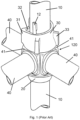
- FIG 1 shows schematically a perspective of a prior art node section 120 used for locking horizontals or the like in a prior art scaffolding system.
- the system is made of steel. Only a single node section 120 is shown. It should be noted, however that each vertical 10, which is delivered in standard lengths, are provided with node sections 120 shown in Figure 1 , preferably equally spaced apart in tube longitudinal direction.
- the system consists of a vertical 10 provided with a bottom cup 20, welded to the vertical 10.
- the bottom cup 20 defines an annular channel 21 (not shown in Figure 1 ) around it, such annular channel 21 being open at its upper end.
- the lower part 22 of the wall of the bottom cup 20 is inclined upwardly and outwardly from the vertical 10 and terminates in a short upper part 24 of cylindrical form.
- the node section 120 also consist at its upper end of a top cup 30 which is slidably and rotatably mounted on the vertical 10 and also defines an annular channel (not shown in Figure 1 ) around it, the annular channel being open at its lower end, the wall of the top cup 30 having a cylindrical upper part which fits loosely around the vertical 10 and a downwardly inclined lower part.
- the top cup 30 has a bulge 31, in which there is formed adjacent to the vertical 10, a vertical slot 32.
- the top face of the top cup 30 may be inclined upwardly from either side of the bulge 31 or continuously for a full 360° from one side, thus forming a wedge-shaped surface.
- the vertical 10 has on one side thereof a lug 12, which is of such size that it can pass through the vertical slot 32 in the bulge 31 of the top cup 30.
- a lug 12 which is of such size that it can pass through the vertical slot 32 in the bulge 31 of the top cup 30.
- a horizontal 40 is at each end provided with a blade end 41 provided with two diametrically opposed fins 42 (not shown).
- the fins 42 on each end of the horizontal 40 are pointing in the same direction.
- the end surface of the blade end 41 is curved, i.e. given a shape that is complimentary to the corresponding shape of the vertical 10.
- the top cup 30 is in a position above the lug 12 on the vertical 10.
- a flanged coupling end (the horizontal's 40 blade end 41) is brought into position with one fin 42 positioned inside the open ended annular channel 21 in the bottom cup 20, also bringing the horizontal 40 into a position where it is perpendicular to the vertical 10.
- the top cup 30 is then lowered by bringing the vertical slot 32 in the top cup 30 in aligned position with the lug 12, whereupon the top cup 30 is lowered down past the lug 12 and around the upper fin 42. In this position, the inclined upper surface of the top cup 30 is positioned below the lower end of the lug 12.
- the top cup 30 In order to lock the position of the horizontal 40, the top cup 30 is rotated in a clockwise direction. Due to the inclining surface of the top cup 30, when the top cup 30 is rotated in this position, the top cup 30 will act as a wedge against the lug 12, forcing the top cup 30 in the downwards direction, thus providing a secure locking engagement between the top cup 30, the blade end 41 and the vertical 10.
- the top cup 30 In order to achieve rotational movement of the top cup 30, the top cup 30 is fitted with top cup lugs 33, spaced apart around the top cup 30, said top cup lugs 33 being intended to be hit by a hammer or a sledge in order to force the top cup 30 into a locking engagement.
- the blade ends 41 which are made of steel, are welded to the end of the horizontal 40.
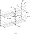
- Figure 3 shows schematically, principally and in perspective a view of a heavy-duty falsework support structure, for example usable for supporting heavy duty steel girders or beams for formwork, for example for supporting formwork for construction of bridges, or the like.
- the falsework is made up of nine verticals 10 and a large number of horizontals 40, adjoined to the respective verticals 10.
- the falsework may be made up of numerous verticals 10 and horizontals 40.
- a typical joint may be made up of four adjoining horizontals 40, forming an angle of 90° between each.
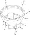
- FIG. 4 shows schematically and in perspective a view of a bottom cup 20 of one embodiment of the present invention.
- the bottom cup is made of metal material, preferably of aluminium, but may also be made of steel.
- a lower part 22 of the wall of the bottom cup 20 preferably forms a lower part 22 of a cylindrical form.
- An intermediate part 23 of the bottom cup 20 is preferably inclined upwardly and outwardly, while an upper part 24 of the bottom cup 20 preferably forms an upper part 24 of cylindrical form.
- Cut-outs in lower end of the bottom cup 20 are drainage recesses 26 for draining purposes, preventing accumulation of water, ice, etc. in the bottom cup 20.
- At least one hole 25 for fastening means 50 (not shown), preferably at the lower part 22 of the bottom cup 20, are furnished at the bottom cup 20.
- Corresponding hole(s) 11 is furnished at the vertical 10.
- the holes 11 at the vertical are preferably susceptible to receive threaded fastening means 50.
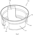
- Figure 5 shows schematically and in perspective a view of a bottom cup guard 110 used to protect the bottom cup 20 (not shown) and fastening means 50 (not shown) from mechanical impacts and environmental elements causing material degradation.
- a lower part 111 of the bottom cup guard 110 forms a lower part 111 of preferably a cylindrical form.
- An upper part 112 of the bottom cup guard 110 forms an upper part 112 preferably inclined upwardly and outwardly.
- a free end of the lower part 111 of the bottom cup guard 110 preferably has a flange 113 orthogonal to the cylindrical form of the lower part 111 directed towards an axial axes of the bottom cup guard 110, having a diameter with a tolerance in order to approximately face the outer surface of the vertical 10 (not shown).
- the bottom cup guard 110 may be furnished with cut-outs in the lower end of the bottom cup guard 110 being drainage recesses 114 corresponding the recesses 26 of the bottom cup 20 (not shown).
- the recesses 114 of the bottom cup guard 110 also serving as draining purposes as those recesses 26 of the bottom cup 20 (not shown), preventing accumulation of water, ice etc. in the bottom cup 20 (not shown).
- the bottom cup guard 110 can be of for example a polymer, such as plastic or rubber.
- the bottom cup guard 110 can also serve as a marketing object, sporting for instance company logo or product name, and/or being in bright colour.
- the bottom cup guard 110 is made up of a single unit and may be applied an adhesive and attached to the bottom cup 20, thus providing permanent joining of the bottom cup guard 110 and the bottom cup 20.
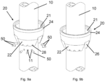
- Figure 6a shows a vertical 10 with preinstalled pairs of bottom cups 20 and a top cups 30 arranged at different levels and spaced along the vertical 10, ready to be installed in a falsework, scaffold or the like and ready to receive bladed ends of horizontals 40 comprising in a falsework, scaffold or the like.
- the top cup 30 is made of metal material, preferably aluminium.
- the vertical 10 shows six pairs of bottom cups 20 and top cups 30, there may be fewer and there may be more, but each vertical 10 shall preferably comprise at least one pair of one bottom cup 20 and one top cup 30. At each end of the vertical 10 there are bolts going straight through the vertical with an accompanying nuts.
- FIG. 6b shows a detail A from figure 6a of the lower part of the vertical 10, showing one pair of a bottom cup 20 and a top cup 30.
- a bottom cup guard 110 (not shown) may also be preinstalled below each pair of bottom cups 20 and top cups 30 arranged at the vertical 10.
- a lug 12 is shown on the vertical 10 arranged above a pair of bottom cups 20 and top cups 30.
- top cup 30 In order to lock the horizontal 40 (not shown), the top cup 30 is rotated in order for top cup 30 to slide it's helical surface 34 towards the lug 12 forcing the top cup 30 in an downward direction.
- the lug 12 and the helical surface 34 acting as a wedge, providing a secure locking engagement.
- Figure 7a shows schematically an exploded view
- Figure 7b shows an assembled view of an assembly of the bottom cup 20 and the top cup 30 of the present invention
- the bottom cup 20 is configured to form an annular channel 21 around the vertical 10 when assembled and fixed to the vertical 10.
- the annular channel 21 is formed by the room between the vertical 10 and surface facing inwards and towards the vertical 10 of the intermediate part 23 and the upper part 24 of the bottom cup 20 as described above in the description of Figure 4 .
- holes 11 in the vertical 10 there should be at least one hole 11, preferably two holes 11, and more preferably three holes 11. These holes 11 in the vertical 10 corresponds to the at least one hole 25 of the bottom cup 20.
- the bottom cup 20 When the bottom cup 20 is lowered or raised in order for the at least one hole 25 in the bottom cup 20 to be at the level of the at least one hole 11 in the vertical 10, the bottom cup 20 should be adjusted to align the axis of the at least one hole 25 in the bottom cup 20 with the axis of the at least one hole in the vertical 10.
- those holes should be distributed around it's circumferences with the same distribution/angle as the at least two holes 11 in the vertical 10 distributed around it's circumferences, the at least two holes 11 being in a common plane approximately orthogonal to a longitudinal axis of the vertical 10.
- At least one fastening means 50 may be threaded through the at least one hole 11, 25 of the vertical 10 and the bottom cup 20.
- the fastening means 50 may preferably be a cap-head socket bolt, but may also be any other suitable threaded or unthreaded bolts, with or without heads, or even pins or wedges.
- the fasting means 50 not fixing the bottom cup 20 to the vertical 10, rather serving as support for the bottom cup 20 to rest on.
- the fixing of the at least one bolt 50 to the vertical 10 via the holes 25 in the bottom cup 20 provides a compressive vertical load capacity of the lower cup via the fastening means as opposed to a tightening of the fastening means between the bottom cup 20 and the vertical 10.
- a bottom cup guard 110 position on the vertical below the bottom cup 20 will be raised towards the bottom cup 20 until the free end of the lower part 111 of the bottom cup guard 110 aligns a free end of the lower part 22 of the bottom cup 20, or until an surface of the flange 113 of the bottom cup guard 110 pointing in direction of the bottom cup 20 is mating against the free end of the lower part 22 of the bottom cup 20.
- the recesses drainage 114 of the bottom cup guard 110 being positioned to align with the drainage recesses 26 of the bottom cup 20 and thereby the draining purposes, preventing accumulation of water, ice, etc. in the bottom cup 20 being fulfilled and protecting the bottom cup 20 and fastening means 50 from mechanical impacts and environmental elements causing material degradation.
- the top cup 30 is arranged above the bottom cup 20, the vertical 10 being in an upraised vertical position.
- the top cup 30 When the lower part of the bladed ends 41 of the horizontals 40 (not shown) is received by the bottom cup 20, the top cup 30 will thereafter be lowered towards the bottom cup 20 and rotated onto the upper part of the blade end 41, by rotating the top cup 30 comprising a helical surface 34 at its upper part against the lug 12, and thereby locking the horizontals 20 to the vertical 10 in a firm locking, but releasable, engagement.
- the top cup 30 is fitted with top cup lugs 33, spaced apart around the top cup 30, said top cup lugs 33 being intended to be hit by a hammer or a sledge in order to force the top cup 30 into the locking engagement.
- Figure 8a shows schematically an exploded view while Figure 8b shows an assembled view of another embodiment of the bottom cup 20 made of steel, fixed to the vertical 10.
- the bottom cup 20 is configured to form an annular channel 21 around the vertical 10 when assembled and fixed to the vertical 10 in aluminium.
- the annular channel 21 is open at its upper end.
- the lower part 22 of the wall of the bottom cup 20 is inclined upwardly and outwardly, while the upper part 24 of the bottom cup 20 forms an upper part 24 of steel with a cylindrical form.
- holes 11 for fastening means 50 are pre-machined in the vertical 10 around its periphery at the same level, into which fastening means 50, preferably dowel pins of steel are fixed, protruding radially out of the vertical 10.
- the holes 11 in the verticals 10 are preferably pre-glued in order to permanently fix the dowel pins 50 to the vertical 10.
- the dowel pins 50 are evenly positioned around the entire circumference of the vertical 10, positioned at the same level.
- the bottom cup 20 is provided with a corresponding number of machined recesses 28 in bottom cup 20 to match the number of dowel pins 50 arranged around the circumference of the vertical 10.
- bottom cup 20 may be machined as a single, integrated unit, thread on to the vertical 10 for appropriate fixing, or the bottom cup 20 may be machined or formed as separate units and subsequently assembled around the vertical. The latter way of assembling will be described below.
- the orientation of the bottom cup 20 is adjusted so as to enable recesses 28 in bottom cup 20 on the lower surface of the bottom cup 20 to rest on the corresponding dowel pins 50. If the vertical 10 is in an upright position, the bottom cup 20 is now resting on the dowel pins 50.
- the bottom cup 20 is permanently connected to the dowel pins 50, and thereby to the vertical 10, preferably through spot welds between bottom cup 20 and each dowel pin 50 and/or by applying glue to either dowel pins 50 and/or the machined recesses 28 in bottom cup 20, thus gluing the bottom cup 20 to the dowel pins 50.
- Cutouts in lower end of bottom cup 20 are drainage recesses 26 for draining purposes, preventing accumulation of water or ice in the bottom cup 20.
- Figure 9a and 9b shows yet another embodiment of the bottom cup 20 of the view shown in Figure 8 , the only major difference being the height of the cylindrical part 15 of the bottom cup 20.
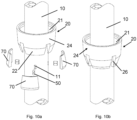
- Figure 10a shows schematically an exploded view of yet another embodiment
- Figure 10b shows an assembled view of the same embodiment of a bottom cup 20.
- upwards and inwards inclined wedges 70 are used for locking the bottom cup 20 to the vertical 10.
- Holes 11 for dowel pins 50 are pre-machined in the vertical 10 around its periphery, in which dowel pins 50 are placed and fixed, protruding out from the outer surface of the vertical 10.
- the holes 11 in the vertical 10 are preferably pre-glued, in order to permanently fix the dowel pins 50 to the vertical 10.
- Glue is applied to the dowel pins 50 protruding out of the outer surface of the vertical 10 and the wedges 70 provided with corresponding machined holes (not shown) to match the dowel pins 50, fixing the wedges 70 to the dowel pins 50 for a permanent fixture on the vertical 10.
- the inner surface at the lower end of the bottom cup 20 is provided with complementary shaped recesses (not shown), configured to receive the wedges 70 and securing the correct position of the bottom cup 20 on the vertical 10.
- the mating surfaces of the wedges 7028 against the vertical 10 might be applied with glue.
- the bottom cup 20 thereafter slides down onto to the wedges 70 for a stiff and firm connection. After the bottom cup 20 is placed onto the wedges 70, welding may be applied between the bottom cup 20 and the wedges 70 in order to insure a fixed connection.
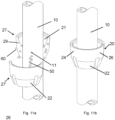
- FIG 11a shows schematically an exploded view of a yet another embodiment of the bottom cup
- Figure 11b shows an assembled view of the same embodiment of the bottom cup 20.
- the bottom cup 20 comprises two identical, but mirrored, bottom cup halves 27, 27'.
- Dowel pins 60 are used to connect both the two bottom cup halves 27, 27' together, and dowel pins 50 are at the same time connecting the two bottom cup halves 27, 27' together with the vertical 10.
- Pre-machined holes 29 in the mating surfaces of the two bottom cup halves 27, 27'and pre-machined holes 11 in the mating surfaces of the two bottom cup halves 27, 27' and the vertical 10 is applied with glue before dowel pins 29, 50 are inserted protruding out of the vertical 10 and one half 27, 27' of the bottom cup 20.
- Glue is filled in the remaining holes 11, 29.
- the bottom cup halves 27, 27' are then joined together with each other and at the same time with the vertical 10 for a permanent connection.
- Figure 8-10 shows cups in one piece, it is not restricted to be manufactured in one piece; it might in all embodiments as shown in figure 8-10 be manufactured in two pieces, joined together as described in figure 11 , with or without dowel pins in combination with gluing and/or welding on joining surfaces, prior to being thread onto the vertical.
- Figure 12a shows schematically an exploded view of an embodiment of a lug 12 for locking of the top cup 30, while Figure 12b shows the unit in an assembled state.
- Holes 13 are pre-machined in the vertical 10 in which dowel pins 130 are placed protruding out of the vertical 10, the holes 13 are preferably pre-glued, in order to permanently fix the dowel pins 130 to the vertical 10.
- Glue is applied to the dowel pins 130 and the face of lug 12, which shall be mated with the vertical 10, before the lug 12, with pre-machined holes to match the dowel pins 130 in the vertical 10, is placed onto the dowel pins 130 for a permanent connection.
- Stoppers 100 which might be dowel pins, shown at the top of the vertical 10 are mechanical stoppers preventing loose objects, such as the top cup 30, from falling off. The stoppers 100 are placed in pre-machined holes in the vertical 10 filled with glue.
- Figure 13a and 13b shows an exploded and assembled view of an embodiment of the end piece of a horizontal 40 with an end piece on each end of an elongated tube 80 of the horizontal 40.
- the long elongated tube 80 of the horizontal 40 being of a light material, such as aluminium, is to be permanently connected to a connecting end piece comprising a blade end 41 with an engaging tube 81, being of a stronger material such as steel.
- the blade end 41 of the end piece fits the shape of the vertical 10, the bottom cup 20 and top cup 30.
- the end piece's engaging tube 81 has a shape to fit within the elongated tube 80 of the horizontal 40.
- the outer surface of the engaging tube 81 of the connecting end piece being applied with glue before being treaded into the elongated tube 80 of the horizontal 40 for a permanent connection.
- the engaging tube 81 is preferably of a semi-cylindrical shape, but it might also take a conical shape, chamfered shape or it might be threaded for a threaded connection between engaging tube 81 and elongated tube 80.
- Figure 14 shows schematically an embodiment of an assembly of the coupling system of the present invention. Showing two horizontals 40, only end part shown, to be connected to the vertical 10 through first lowering one side of the blade end 41 into the preinstalled, permanent bottom cup 20 as described in Figure 7 , 8 , 9 , 10 and 11 . A top cup 30 is thereafter lowered and rotated onto the other side of the blade end 41, by rotating the top cup 30 comprising a helical upper part against the lug 12 described in Figure 12 , and thereby locking the horizontals 40 to the vertical 10 in a firm but releasable connection.
- a support bracket 90 may be assembled between the vertical 10 and horizontal 40 in order to aid the transfer of loads between the horizontal 40 and the vertical 10 creating a stronger and more rigid connection between the horizontal 40 and the vertical 10.
- the support bracket 90 is configured to be securely fixed to the vertical 10 below the node section 120 and the horizontal 40 at a distance from the node section 120, thereby forming a strut or a brace.
- the support bracket 90 will be described in further details below, referring to Figure 15a and 15b .
- Figure 15a and 15b shows an exploded and assembled view of an embodiment of the support bracket 90 mentioned in Figure 14 comprising two identical but mirrored support bracket plates 91, 91', being shaped steel or aluminium plates, able to grip around both the horizontal 40 and the vertical 10.
- the two support bracket plates 91, 91' are loosely connected with bolts 93, washers 95 and nuts 96 before assembled in order to be fastened together and tightened around the horizontal 40 and the vertical 10.
- the bolts 93 which may be carriage bolts used with corresponding squared holes 94 in the support bracket plates 91, 91' in order to keep the bolts 933 in place while screwing the nuts 96 and tightening the parts together or loosening the parts, thereby eliminating the need of an extra holding-on tool while tightening of loosening of the parts.
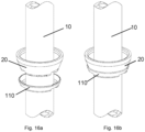
- Figure 16a and 16b shows an exploded and assembled view of an embodiment of a bottom cup guard 110 used to protect the bottom cup 20, dowel pins 50 and joining adhesive from mechanical impacts and environmental elements causing material degradation.
- the bottom cup guard 110 can be for instance of a polymer material such as plastic or rubber.
- the bottom cup guard 110 can also serve as a marketing object, sporting for instance company logo or product name, and/or being in bright colour.
- the bottom cup guard 110 is made up of a single unit and is applied an adhesive and attached to the bottom cup 20, thus providing permanent joining of the bottom cup guard 110 and the bottom cup 20.
Landscapes
- Engineering & Computer Science (AREA)
- Architecture (AREA)
- Mechanical Engineering (AREA)
- Civil Engineering (AREA)
- Structural Engineering (AREA)
- Mutual Connection Of Rods And Tubes (AREA)
- Forms Removed On Construction Sites Or Auxiliary Members Thereof (AREA)
Claims (16)
- Strukturstützsystem, wie beispielsweise, aber nicht beschränkt auf ein Gerüst oder ein Lehrgerüst, umfassend Vertikale (10), Horizontale (40) und/oder Diagonale, die an Knotenabschnitten (120) an den Vertikalen (10) verbunden sind, wobei jeder Knotenabschnitt (120) eine Verriegelungsvorrichtung zum Verbinden von Horizontalen (40) und/oder Diagonalen mit an den Enden der Horizontalen (40) und/oder Diagonalen und der Vertikalen (10) angeordneten beschaufelte Enden umfasst, wobei die Verriegelungsvorrichtung ein Becherpaar ist, umfassend einen unteren Becher (20), der an einer Position an den Vertikalen (10) gehalten wird, und einen oberen Becher (30), der beweglich an den Vertikalen (10) angeordnet ist, wobei beschaufelte Enden der Horizontalen (40) und/oder Diagonalen dazu konfiguriert sind, durch den unteren Becherteil (20) und den oberen Becherteil (30) verriegelt zu werden, um eine starre Verbindung bereitzustellen,der untere Becher (20) mindestens ein Loch (25) umfasst, vorzugsweise an dem Umfang eines unteren Teils (22) des unteren Bechers (20),die unteren Becher (20) an einer Position an den Vertikalen (10) unter Verwendung von mindestens einem Befestigungsmittel (50) und entsprechenden Löchern (11, 25) in den unteren Bechern (20) und den Vertikalen (10) gehalten werden, wobei das Befestigungsmittel (50) eine Kopfschraube ist, die durch Einschrauben der Kopfschraube in die Vertikale (10) starr befestigt wird,dadurch gekennzeichnet, dass der Durchmesser des Lochs (25) des unteren Bechers (20) größer ist als der Durchmesser des Kopfes der Kopfschraube, sodass das Loch (25) des unteren Bechers (20) auf dem Kopf der Kopfschraube aufliegt und eine Druckbelastbarkeit in vertikaler und/oder horizontaler Richtung des unteren Bechers (20) über die Schraube bereitstellt.
- Strukturstützsystem nach Anspruch 1, wobei der untere Becher (20) den unteren Teil (22), vorzugsweise in zylindrischer Form, einen Zwischenteil (23), vorzugsweise nach oben und außen geneigt, und einen oberen Teil (24), vorzugsweise in zylindrischer Form, umfasst.
- Strukturstützsystem nach Anspruch 1 oder 2, wobei das Loch/die Löcher (25) in dem unteren Becher ohne Gewinde ist/sind.
- Strukturstützsystem nach einem der Ansprüche 1 bis 3, wobei der untere Becher (20) ferner mindestens eine Entwässerungsaussparung (26) in dem unteren Teil (22) des unteren Bechers (20) umfasst.
- Strukturstützsystem nach einem der Ansprüche 1 bis 4, wobei das System ferner einen unteren Becherschutz (110) umfasst.
- Strukturstützsystem nach Anspruch 5, wobei der untere Becherschutz (110) einen unteren Teil (111), vorzugsweise in zylindrischer Form, und einen oberen Teil (112), vorzugsweise nach oben und außen geneigt, umfasst.
- Strukturstützsystem nach Anspruch 6, wobei der untere Becherschutz (110) ferner mindestens eine Entwässerungsaussparung (114) mindestens in dem unteren Teil (111) des unteren Becherschutzes (110) umfasst, vorzugsweise mit derselben Höhe und Breite wie die Entwässerungsaussparung (26) des unteren Bechers (20).
- Strukturstützsystem nach Anspruch 5 oder 6, wobei der untere Becherschutz (110) ferner einen Flansch (113) an dem freien Ende des unteren Teils (111) des unteren Becherschutzes (110) umfasst, der nach innen zeigt, wobei der untere Becherschutz (110) einen Durchmesser mit einer Toleranz aufweist, um ungefähr der Außenfläche der Vertikalen (10) zugewandt zu sein.
- Strukturstützsystem nach einem der vorstehenden Ansprüche, wobei die Horizontale (40) ein längliches Rohr (80) und ein Schaufelende (41) mit Rippen (42) mit einem Eingriffsrohr (81) umfasst, wobei das Eingriffsrohr (81) und das Schaufelende (41) dauerhaft verbunden sind und ferner dauerhaft mit dem länglichen Rohr (80) durch Auftragen von Klebstoff auf die Verbindungsflächen verbunden sind, wobei die Verbindungsflächen die Innenfläche des länglichen Rohrs (80) und die Außenfläche des Eingriffsrohrs (81) sind.
- Strukturstützsystem nach Anspruch 9, wobei das längliche Rohr (80), das vorzugsweise halbzylindrisch geformt ist, auf das Eingriffsrohr (81) geschraubt ist, das vorzugsweise halbzylindrisch geformt ist, aber auch konisch geformt, abgeschrägt oder sogar mit einem Gewinde für eine Gewindeverbindung zwischen dem Eingriffsrohr (81) und dem länglichen Rohr (80) versehen sein kann.
- Strukturstützsystem nach einem der Ansprüche 1 bis 10, wobei der installierte untere Becher (20) mit einem unteren Becherschutz (110) abgedeckt ist, um den unteren Becher (20), die Befestigungsmittel (50) und das Bindemittel vor mechanischen Einwirkungen und Umwelteinflüssen zu schützen, die eine Materialverschlechterung verursachen.
- Strukturstützsystem nach Anspruch 11, wobei das für den unteren Becherschutz (110) verwendete Material aus einem Polymer, wie Kunststoff oder Gummi, besteht.
- Strukturstützsystem nach einem der Ansprüche 1 bis 12, wobei die Horizontalen (40) mit einer zusätzlichen Stützhalterung (90) gestützt werden, um Kräfte zwischen den Horizontalen (40) und den Vertikalen (10) zu übertragen, wobei die Stützhalterung (90) zwei identische, aber spiegelbildlich geformte Stahl- oder Aluminiumplatten (91, 91') umfasst, um in der Lage zu sein, um die Horizontalen (40) und die Vertikalen (10) herum zu greifen, wobei die beiden Platten (91, 91') lose mit Schrauben (93), Unterlegscheiben (95) und Muttern (96) verbunden sind, um miteinander verschraubt und um die Horizontalen (40) und Vertikalen (10) herum festgezogen zu werden.
- Verfahren zum Montieren eines Knotenabschnitts (120) an einer Vertikalen (10) zur Verwendung in einem Strukturstützsystem nach einem der Ansprüche 1 bis 13, wobei jeder Knotenabschnitt (120) eine Verriegelungsvorrichtung zum Verbinden von Horizontalen und/oder Diagonalen mit beschaufelten Enden ist, die an Enden der Horizontalen (40) und/oder Diagonalen mit Vertikalen (10) angeordnet sind, wobei die Verriegelungsvorrichtung ein Becher ist, umfassend einen unteren Becher (20) aus Metallmaterial, vorzugsweise Aluminium oder Stahl, der an einer vorbestimmten Position an den Vertikalen (10) gehalten wird, und einen oberen Becher (30) aus Metallmaterial, vorzugsweise Aluminium, der beweglich mit den Vertikalen (10) verbunden ist,
dadurch gekennzeichnet, dass die Vertikale (10) aus stranggepressten Aluminiumrohren geformt ist, ein oder mehrere radial ausgerichtete Löcher (11) in die Außenfläche der Vertikalen (10) geformt sind, die Oberfläche jedes Lochs (11) vorzugsweise mit einem Gewinde versehen ist, die Löcher (25) in dem unteren Becher (20) mit den Löchern (11) in der Vertikalen (10) positioniert werden und ein Befestigungsmittel (50) aus Stahl in jedes der Löcher (11) über die Löcher (25) in dem unteren Becher (20) eingeführt wird. - Verfahren nach Anspruch 14, wobei ein auf die Vertikale (10) aufgeschraubter unterer Becherschutz (110) in Richtung des unteren Bechers (20) angehoben wird, bis das freie Ende des unteren Teils (111) des unteren Becherschutzes (110) mit einem freien Ende des unteren Teils (22) des unteren Bechers (20) ausgerichtet ist, oder bis eine Fläche des Flansches (113) des unteren Becherschutzes (110), die in Richtung des unteren Bechers (20) zeigt, gegen das freie Ende des unteren Teils (22) des unteren Bechers (20) passt.
- Verfahren nach Anspruch 15, wobei der untere Becherschutz (110) in Position eingestellt wird, wobei Entwässerungsaussparungen (114) in dem unteren Becherschutz (110) mit Entwässerungsaussparungen (26) in dem unteren Becher (20) ausgerichtet sind.
Priority Applications (2)
| Application Number | Priority Date | Filing Date | Title |
|---|---|---|---|
| HRP20250992TT HRP20250992T1 (hr) | 2018-03-20 | 2019-03-20 | Sustav strukturnih potporanja i postupak koji osigurava čvorni odjeljak namijenjen upotrebi u sustavu strukturnih potporanja |
| RS20250736A RS67126B1 (sr) | 2018-03-20 | 2019-03-20 | Sistem pomoćne konstrukcije i metod za obezbeđivanje čvornog dela za upotrebu u sistemu pomoćne konstrukcije |
Applications Claiming Priority (2)
| Application Number | Priority Date | Filing Date | Title |
|---|---|---|---|
| NO20180392 | 2018-03-20 | ||
| PCT/NO2019/050060 WO2019182457A1 (en) | 2018-03-20 | 2019-03-20 | A structural support system and a method for providing a node section for use in a structural support system |
Publications (4)
| Publication Number | Publication Date |
|---|---|
| EP3768917A1 EP3768917A1 (de) | 2021-01-27 |
| EP3768917A4 EP3768917A4 (de) | 2021-12-08 |
| EP3768917B1 true EP3768917B1 (de) | 2025-05-21 |
| EP3768917C0 EP3768917C0 (de) | 2025-05-21 |
Family
ID=67987892
Family Applications (1)
| Application Number | Title | Priority Date | Filing Date |
|---|---|---|---|
| EP19771525.3A Active EP3768917B1 (de) | 2018-03-20 | 2019-03-20 | Strukturträgersystem und verfahren zur bereitstellung eines knotenabschnitts zur verwendung in einem strukturträgersystem |
Country Status (10)
| Country | Link |
|---|---|
| US (1) | US20210025182A1 (de) |
| EP (1) | EP3768917B1 (de) |
| AU (1) | AU2019239014B2 (de) |
| CA (1) | CA3094450A1 (de) |
| ES (1) | ES3037143T3 (de) |
| HR (1) | HRP20250992T1 (de) |
| HU (1) | HUE072431T2 (de) |
| PL (1) | PL3768917T3 (de) |
| RS (1) | RS67126B1 (de) |
| WO (1) | WO2019182457A1 (de) |
Families Citing this family (6)
| Publication number | Priority date | Publication date | Assignee | Title |
|---|---|---|---|---|
| GB2580067B (en) * | 2018-12-20 | 2021-06-16 | Kingsmead Developments Sw Ltd | A coupling system |
| US12227244B2 (en) * | 2021-03-25 | 2025-02-18 | Safesmart Llc | Safety rail |
| CN113187805A (zh) * | 2021-04-21 | 2021-07-30 | 中建七局建筑装饰工程有限公司 | 一种多构件交汇点机械连接装置 |
| CN114775996A (zh) * | 2022-05-27 | 2022-07-22 | 东莞市建筑科学研究院有限公司 | 上旋扣件脚手架及其施工方法 |
| CN115419253B (zh) * | 2022-09-13 | 2024-02-06 | 南京宏亚建设集团有限公司 | 建筑脚手架连接装置 |
| CN119616189B (zh) * | 2024-12-25 | 2025-09-26 | 中国十九冶集团有限公司 | 用于脚手架主节点架设的旋转连接结构 |
Family Cites Families (37)
| Publication number | Priority date | Publication date | Assignee | Title |
|---|---|---|---|---|
| US1714215A (en) * | 1927-05-17 | 1929-05-21 | Stephen L Gardner | Scaffold |
| US2057329A (en) * | 1934-12-10 | 1936-10-13 | Duff John | Tubular scaffolding |
| US2583368A (en) * | 1947-06-11 | 1952-01-22 | Merle P French | Coupling means for scaffolding bars |
| US3395501A (en) * | 1966-01-03 | 1968-08-06 | Harsco Corp | Hoist tower |
| US3388511A (en) * | 1966-11-29 | 1968-06-18 | Harsco Corp | Multiple shaft tower construction |
| US3693309A (en) * | 1970-08-19 | 1972-09-26 | Jacob H Kutchai | Shoring system |
| FR2216845A5 (de) * | 1973-01-31 | 1974-08-30 | Mills Echafaudages | |
| NL175840B (nl) * | 1973-10-10 | 1984-08-01 | Sgb Group Plc | Verbindingsconstructie voor toepassing in een buisvormige steiger of stelling. |
| FR2298720A1 (fr) * | 1975-01-27 | 1976-08-20 | Chamayou Gerard | Noeuds d'assemblage pour structures multidirectionnelles et structures comportant de tels noeuds |
| NL8005954A (nl) * | 1980-10-30 | 1982-05-17 | Petrus Johannes Lambertus De L | Koppeling. |
| WO1993001380A1 (en) * | 1991-07-12 | 1993-01-21 | Ronald Lubinski | Aluminum scaffold system |
| US6183167B1 (en) * | 1999-01-15 | 2001-02-06 | Richard D. Ruiz, Llc | Pipe pier system |
| NO313709B1 (no) * | 2000-02-16 | 2002-11-18 | Malthus As | Anvendelse av en festeskinne for forankring av presenning i stillas, arbeidstelt, etc. |
| FR2846990B3 (fr) * | 2002-11-07 | 2004-10-22 | Escalona Fernando Falcon | Protecteur pour couvrir tout type de partie saillante structurelle sur echafaudage |
| JP2005068650A (ja) * | 2003-08-25 | 2005-03-17 | Alinco Inc | 安全手摺 |
| US7854564B1 (en) * | 2006-03-31 | 2010-12-21 | Uncommon Usa, Inc. | Pole assembly |
| CN200978854Y (zh) * | 2006-09-28 | 2007-11-21 | 刘成文 | 一种可拆装式紧固连接装置 |
| CA2638365C (en) * | 2008-07-29 | 2011-07-12 | Peter J. Rogers | Twist lock coupling spigot |
| USD656814S1 (en) * | 2010-11-01 | 2012-04-03 | Bauer Ryan E | Hinged cuplock scaffolding coupler |
| US20120219354A1 (en) * | 2011-02-24 | 2012-08-30 | Bauer Ryan E | Cup-lock coupler clamp for detachably attaching at any elevation on a vertical tube of the cup-lock scaffold system |
| CA2740549C (en) * | 2011-05-17 | 2018-09-25 | Athos Construction Products, Inc. | Glued ledger head |
| CN102704670B (zh) * | 2012-06-24 | 2014-05-07 | 郑德春 | 碗扣式脚手架用下碗扣及其安装方法 |
| CN102817890A (zh) * | 2012-09-05 | 2012-12-12 | 江苏鑫润铝业集团有限公司 | 一种扣件 |
| CN203034788U (zh) * | 2013-01-11 | 2013-07-03 | 王新宏 | 一种快速装卸活动的脚手架 |
| CN203271112U (zh) * | 2013-04-15 | 2013-11-06 | 吴伟林 | 一种碗扣式脚手架用碗扣 |
| US9404273B2 (en) * | 2013-06-12 | 2016-08-02 | Richard Dawson | Scaffold end cover system and method |
| CA2836564C (en) * | 2013-12-12 | 2021-02-16 | Athos Construction Products, Inc. | Cup connector for scaffold |
| CN205046830U (zh) * | 2015-09-29 | 2016-02-24 | 孔丽 | 碗扣式钢管脚手架 |
| CN105421757B (zh) * | 2015-12-03 | 2017-09-19 | 无锡市晨源建筑器材有限公司 | 一种碗扣式脚手架的碗扣接头 |
| CN205935627U (zh) * | 2016-08-19 | 2017-02-08 | 董三升 | 一种碗扣钢管结构 |
| CN206503344U (zh) * | 2016-12-22 | 2017-09-19 | 天津市天润海业建筑工程设计有限公司 | 一种建筑工程用的脚手架 |
| CN208056616U (zh) * | 2017-12-14 | 2018-11-06 | 江西天艺钢结构有限公司 | 一种用于建筑钢架的连接固定装置 |
| CN208137413U (zh) * | 2018-05-03 | 2018-11-23 | 宜昌海纳川建设工程有限公司 | 一种碗扣式钢管脚手架 |
| DE102019117082A1 (de) * | 2018-11-26 | 2020-05-28 | Peri Gmbh | Gerüstknoten |
| GB2580067B (en) * | 2018-12-20 | 2021-06-16 | Kingsmead Developments Sw Ltd | A coupling system |
| NO345872B1 (en) * | 2019-07-12 | 2021-09-20 | Frico As | A tubular transom for scaffolding or falsework having ends configured to be connected to verticals at node sections. |
| CN111776581A (zh) * | 2019-08-29 | 2020-10-16 | 北京京东乾石科技有限公司 | 物品拣选系统及拣选方法 |
-
2019
- 2019-03-20 HU HUE19771525A patent/HUE072431T2/hu unknown
- 2019-03-20 RS RS20250736A patent/RS67126B1/sr unknown
- 2019-03-20 HR HRP20250992TT patent/HRP20250992T1/hr unknown
- 2019-03-20 PL PL19771525.3T patent/PL3768917T3/pl unknown
- 2019-03-20 US US16/981,218 patent/US20210025182A1/en active Pending
- 2019-03-20 CA CA3094450A patent/CA3094450A1/en active Pending
- 2019-03-20 WO PCT/NO2019/050060 patent/WO2019182457A1/en not_active Ceased
- 2019-03-20 AU AU2019239014A patent/AU2019239014B2/en active Active
- 2019-03-20 EP EP19771525.3A patent/EP3768917B1/de active Active
- 2019-03-20 ES ES19771525T patent/ES3037143T3/es active Active
Also Published As
| Publication number | Publication date |
|---|---|
| HRP20250992T1 (hr) | 2025-10-24 |
| RS67126B1 (sr) | 2025-09-30 |
| AU2019239014A1 (en) | 2020-10-01 |
| PL3768917T3 (pl) | 2025-10-20 |
| US20210025182A1 (en) | 2021-01-28 |
| WO2019182457A1 (en) | 2019-09-26 |
| ES3037143T3 (en) | 2025-09-29 |
| EP3768917A4 (de) | 2021-12-08 |
| HUE072431T2 (hu) | 2025-11-28 |
| CA3094450A1 (en) | 2019-09-26 |
| AU2019239014B2 (en) | 2025-01-30 |
| EP3768917C0 (de) | 2025-05-21 |
| EP3768917A1 (de) | 2021-01-27 |
Similar Documents
| Publication | Publication Date | Title |
|---|---|---|
| EP3768917B1 (de) | Strukturträgersystem und verfahren zur bereitstellung eines knotenabschnitts zur verwendung in einem strukturträgersystem | |
| US5499885A (en) | Apparatus for joining structural components | |
| US8303207B2 (en) | Hybrid scaffold system | |
| US20020079165A1 (en) | Scaffolding system having improved safety structures and connecting members | |
| KR101117546B1 (ko) | 가설 흙막이 공법용 사각강관 버팀보의 연결 및 접합 시공구조 및 그 시공구조를 위한 연결보강부재와 접합보강부재 | |
| US20130074440A1 (en) | Geometric connecting assembly and method for braced frame connections | |
| CA2104866A1 (en) | Structural connector approximating a cone of elliptical cross-section | |
| US10570630B2 (en) | Suspended scaffolding structure and connector therefor | |
| KR101143076B1 (ko) | 뭉치형 사다리 작업대 | |
| CN106939690B (zh) | 一种抗倾承重脚手架 | |
| CN111173250A (zh) | 一种脚手架的斜拉式悬挑梁支撑体系 | |
| CN110541484B (zh) | 建筑用装配式集成框架 | |
| CN212295578U (zh) | 一种脚手架的斜拉式悬挑梁支撑体系 | |
| JP7098079B1 (ja) | 鋼材の接合構造 | |
| EP0293101A2 (de) | Verfahren zur Herstellung einer Winkelverbindung | |
| CN215167925U (zh) | 限位扣件、外架连墙组件及外架连墙结构 | |
| WO2013150439A1 (en) | Modular scaffold | |
| WO2023018940A2 (en) | Collapsible utility scaffold | |
| KR20100031030A (ko) | 철골 커플링 장치 | |
| KR101914679B1 (ko) | 결합부재가 구비된 강관 버팀보 | |
| CN217975342U (zh) | 一种外脚手架连墙件及外脚手架 | |
| CN219261741U (zh) | 一种外梁模板托架 | |
| CN218027723U (zh) | 一种便于拆装的基坑支护装置 | |
| CN114108998B (zh) | 一种建筑施工架 | |
| AU2006235786B2 (en) | A utility pole joint |
Legal Events
| Date | Code | Title | Description |
|---|---|---|---|
| REG | Reference to a national code |
Ref country code: HR Ref legal event code: TUEP Ref document number: P20250992T Country of ref document: HR |
|
| STAA | Information on the status of an ep patent application or granted ep patent |
Free format text: STATUS: THE INTERNATIONAL PUBLICATION HAS BEEN MADE |
|
| PUAI | Public reference made under article 153(3) epc to a published international application that has entered the european phase |
Free format text: ORIGINAL CODE: 0009012 |
|
| STAA | Information on the status of an ep patent application or granted ep patent |
Free format text: STATUS: REQUEST FOR EXAMINATION WAS MADE |
|
| 17P | Request for examination filed |
Effective date: 20201020 |
|
| AK | Designated contracting states |
Kind code of ref document: A1 Designated state(s): AL AT BE BG CH CY CZ DE DK EE ES FI FR GB GR HR HU IE IS IT LI LT LU LV MC MK MT NL NO PL PT RO RS SE SI SK SM TR |
|
| AX | Request for extension of the european patent |
Extension state: BA ME |
|
| DAV | Request for validation of the european patent (deleted) | ||
| DAX | Request for extension of the european patent (deleted) | ||
| A4 | Supplementary search report drawn up and despatched |
Effective date: 20211105 |
|
| RIC1 | Information provided on ipc code assigned before grant |
Ipc: E04G 7/30 20060101ALI20211101BHEP Ipc: E04G 7/34 20060101ALI20211101BHEP Ipc: E04G 7/14 20060101ALI20211101BHEP Ipc: E04G 5/00 20060101ALI20211101BHEP Ipc: E04G 1/04 20060101ALI20211101BHEP Ipc: E04G 11/48 20060101ALI20211101BHEP Ipc: E04G 7/22 20060101AFI20211101BHEP |
|
| GRAP | Despatch of communication of intention to grant a patent |
Free format text: ORIGINAL CODE: EPIDOSNIGR1 |
|
| STAA | Information on the status of an ep patent application or granted ep patent |
Free format text: STATUS: GRANT OF PATENT IS INTENDED |
|
| INTG | Intention to grant announced |
Effective date: 20241213 |
|
| GRAS | Grant fee paid |
Free format text: ORIGINAL CODE: EPIDOSNIGR3 |
|
| GRAA | (expected) grant |
Free format text: ORIGINAL CODE: 0009210 |
|
| STAA | Information on the status of an ep patent application or granted ep patent |
Free format text: STATUS: THE PATENT HAS BEEN GRANTED |
|
| AK | Designated contracting states |
Kind code of ref document: B1 Designated state(s): AL AT BE BG CH CY CZ DE DK EE ES FI FR GB GR HR HU IE IS IT LI LT LU LV MC MK MT NL NO PL PT RO RS SE SI SK SM TR |
|
| REG | Reference to a national code |
Ref country code: GB Ref legal event code: FG4D |
|
| REG | Reference to a national code |
Ref country code: CH Ref legal event code: EP |
|
| REG | Reference to a national code |
Ref country code: DE Ref legal event code: R096 Ref document number: 602019070274 Country of ref document: DE |
|
| REG | Reference to a national code |
Ref country code: IE Ref legal event code: FG4D |
|
| U01 | Request for unitary effect filed |
Effective date: 20250620 |
|
| U07 | Unitary effect registered |
Designated state(s): AT BE BG DE DK EE FI FR IT LT LU LV MT NL PT RO SE SI Effective date: 20250701 |
|
| REG | Reference to a national code |
Ref country code: ES Ref legal event code: FG2A Ref document number: 3037143 Country of ref document: ES Kind code of ref document: T3 Effective date: 20250929 |
|
| REG | Reference to a national code |
Ref country code: HR Ref legal event code: T1PR Ref document number: P20250992 Country of ref document: HR |
|
| REG | Reference to a national code |
Ref country code: SK Ref legal event code: T3 Ref document number: E 46978 Country of ref document: SK |
|
| REG | Reference to a national code |
Ref country code: GR Ref legal event code: EP Ref document number: 20250401683 Country of ref document: GR Effective date: 20251009 |
|
| REG | Reference to a national code |
Ref country code: HU Ref legal event code: AG4A Ref document number: E072431 Country of ref document: HU |