EP3768572B1 - Chassis for a roll container and a roll container comprising the same - Google Patents
Chassis for a roll container and a roll container comprising the same Download PDFInfo
- Publication number
- EP3768572B1 EP3768572B1 EP19771076.7A EP19771076A EP3768572B1 EP 3768572 B1 EP3768572 B1 EP 3768572B1 EP 19771076 A EP19771076 A EP 19771076A EP 3768572 B1 EP3768572 B1 EP 3768572B1
- Authority
- EP
- European Patent Office
- Prior art keywords
- chassis
- arm
- crossmember
- roll container
- casters
- Prior art date
- Legal status (The legal status is an assumption and is not a legal conclusion. Google has not performed a legal analysis and makes no representation as to the accuracy of the status listed.)
- Active
Links
- 230000008878 coupling Effects 0.000 claims description 16
- 238000010168 coupling process Methods 0.000 claims description 16
- 238000005859 coupling reaction Methods 0.000 claims description 16
- 239000000463 material Substances 0.000 claims description 7
- 239000002131 composite material Substances 0.000 claims description 4
- 239000004952 Polyamide Substances 0.000 claims description 3
- 229920002647 polyamide Polymers 0.000 claims description 3
- 229910052751 metal Inorganic materials 0.000 claims description 2
- 239000002184 metal Substances 0.000 claims description 2
- 229920000642 polymer Polymers 0.000 claims description 2
- OKTJSMMVPCPJKN-UHFFFAOYSA-N Carbon Chemical compound [C] OKTJSMMVPCPJKN-UHFFFAOYSA-N 0.000 description 5
- 229910052799 carbon Inorganic materials 0.000 description 5
- 238000010276 construction Methods 0.000 description 5
- 230000000712 assembly Effects 0.000 description 4
- 238000000429 assembly Methods 0.000 description 4
- 239000007787 solid Substances 0.000 description 3
- 238000003466 welding Methods 0.000 description 3
- 235000004443 Ricinus communis Nutrition 0.000 description 2
- 240000000528 Ricinus communis Species 0.000 description 2
- 238000006073 displacement reaction Methods 0.000 description 2
- 238000004880 explosion Methods 0.000 description 2
- 230000003993 interaction Effects 0.000 description 2
- 239000004033 plastic Substances 0.000 description 2
- 229920003023 plastic Polymers 0.000 description 2
- -1 polyethylene Polymers 0.000 description 2
- 230000008439 repair process Effects 0.000 description 2
- 229910000838 Al alloy Inorganic materials 0.000 description 1
- 239000004698 Polyethylene Substances 0.000 description 1
- 239000004743 Polypropylene Substances 0.000 description 1
- 229910000831 Steel Inorganic materials 0.000 description 1
- 238000013459 approach Methods 0.000 description 1
- 238000005452 bending Methods 0.000 description 1
- 230000015572 biosynthetic process Effects 0.000 description 1
- 230000001419 dependent effect Effects 0.000 description 1
- 230000009977 dual effect Effects 0.000 description 1
- 230000000694 effects Effects 0.000 description 1
- 230000005489 elastic deformation Effects 0.000 description 1
- 239000000835 fiber Substances 0.000 description 1
- 239000011521 glass Substances 0.000 description 1
- 238000011065 in-situ storage Methods 0.000 description 1
- 230000004048 modification Effects 0.000 description 1
- 238000012986 modification Methods 0.000 description 1
- 238000012856 packing Methods 0.000 description 1
- 230000002093 peripheral effect Effects 0.000 description 1
- 229920000573 polyethylene Polymers 0.000 description 1
- 229920001155 polypropylene Polymers 0.000 description 1
- 230000001737 promoting effect Effects 0.000 description 1
- 239000010959 steel Substances 0.000 description 1
- 238000003860 storage Methods 0.000 description 1
Images


Classifications
-
- B—PERFORMING OPERATIONS; TRANSPORTING
- B62—LAND VEHICLES FOR TRAVELLING OTHERWISE THAN ON RAILS
- B62B—HAND-PROPELLED VEHICLES, e.g. HAND CARTS OR PERAMBULATORS; SLEDGES
- B62B3/00—Hand carts having more than one axis carrying transport wheels; Steering devices therefor; Equipment therefor
- B62B3/02—Hand carts having more than one axis carrying transport wheels; Steering devices therefor; Equipment therefor involving parts being adjustable, collapsible, attachable, detachable or convertible
-
- B—PERFORMING OPERATIONS; TRANSPORTING
- B62—LAND VEHICLES FOR TRAVELLING OTHERWISE THAN ON RAILS
- B62B—HAND-PROPELLED VEHICLES, e.g. HAND CARTS OR PERAMBULATORS; SLEDGES
- B62B3/00—Hand carts having more than one axis carrying transport wheels; Steering devices therefor; Equipment therefor
- B62B3/14—Hand carts having more than one axis carrying transport wheels; Steering devices therefor; Equipment therefor characterised by provisions for nesting or stacking, e.g. shopping trolleys
- B62B3/18—Hand carts having more than one axis carrying transport wheels; Steering devices therefor; Equipment therefor characterised by provisions for nesting or stacking, e.g. shopping trolleys nestable by means of pivoted supports or support parts, e.g. baskets
- B62B3/184—Nestable roll containers
- B62B3/186—V-shaped when nested
-
- B—PERFORMING OPERATIONS; TRANSPORTING
- B62—LAND VEHICLES FOR TRAVELLING OTHERWISE THAN ON RAILS
- B62B—HAND-PROPELLED VEHICLES, e.g. HAND CARTS OR PERAMBULATORS; SLEDGES
- B62B3/00—Hand carts having more than one axis carrying transport wheels; Steering devices therefor; Equipment therefor
- B62B3/002—Hand carts having more than one axis carrying transport wheels; Steering devices therefor; Equipment therefor characterised by a rectangular shape, involving sidewalls or racks
-
- B—PERFORMING OPERATIONS; TRANSPORTING
- B62—LAND VEHICLES FOR TRAVELLING OTHERWISE THAN ON RAILS
- B62B—HAND-PROPELLED VEHICLES, e.g. HAND CARTS OR PERAMBULATORS; SLEDGES
- B62B3/00—Hand carts having more than one axis carrying transport wheels; Steering devices therefor; Equipment therefor
- B62B3/02—Hand carts having more than one axis carrying transport wheels; Steering devices therefor; Equipment therefor involving parts being adjustable, collapsible, attachable, detachable or convertible
- B62B3/025—Foldable roll containers
-
- B—PERFORMING OPERATIONS; TRANSPORTING
- B62—LAND VEHICLES FOR TRAVELLING OTHERWISE THAN ON RAILS
- B62B—HAND-PROPELLED VEHICLES, e.g. HAND CARTS OR PERAMBULATORS; SLEDGES
- B62B2205/00—Hand-propelled vehicles or sledges being foldable or dismountable when not in use
- B62B2205/006—Hand-propelled vehicles or sledges being foldable or dismountable when not in use dismountable
-
- B—PERFORMING OPERATIONS; TRANSPORTING
- B62—LAND VEHICLES FOR TRAVELLING OTHERWISE THAN ON RAILS
- B62B—HAND-PROPELLED VEHICLES, e.g. HAND CARTS OR PERAMBULATORS; SLEDGES
- B62B2301/00—Wheel arrangements; Steering; Stability; Wheel suspension
- B62B2301/04—Wheel arrangements; Steering; Stability; Wheel suspension comprising a wheel pivotable about a substantially vertical axis, e.g. swivelling castors
-
- B—PERFORMING OPERATIONS; TRANSPORTING
- B62—LAND VEHICLES FOR TRAVELLING OTHERWISE THAN ON RAILS
- B62B—HAND-PROPELLED VEHICLES, e.g. HAND CARTS OR PERAMBULATORS; SLEDGES
- B62B2301/00—Wheel arrangements; Steering; Stability; Wheel suspension
- B62B2301/05—Details of the attachment of the wheel assembly to the chassis
-
- B—PERFORMING OPERATIONS; TRANSPORTING
- B62—LAND VEHICLES FOR TRAVELLING OTHERWISE THAN ON RAILS
- B62B—HAND-PROPELLED VEHICLES, e.g. HAND CARTS OR PERAMBULATORS; SLEDGES
- B62B2501/00—Manufacturing; Constructional features
- B62B2501/06—Materials used
-
- B—PERFORMING OPERATIONS; TRANSPORTING
- B62—LAND VEHICLES FOR TRAVELLING OTHERWISE THAN ON RAILS
- B62B—HAND-PROPELLED VEHICLES, e.g. HAND CARTS OR PERAMBULATORS; SLEDGES
- B62B2501/00—Manufacturing; Constructional features
- B62B2501/06—Materials used
- B62B2501/065—Plastics
-
- B—PERFORMING OPERATIONS; TRANSPORTING
- B62—LAND VEHICLES FOR TRAVELLING OTHERWISE THAN ON RAILS
- B62B—HAND-PROPELLED VEHICLES, e.g. HAND CARTS OR PERAMBULATORS; SLEDGES
- B62B3/00—Hand carts having more than one axis carrying transport wheels; Steering devices therefor; Equipment therefor
- B62B3/14—Hand carts having more than one axis carrying transport wheels; Steering devices therefor; Equipment therefor characterised by provisions for nesting or stacking, e.g. shopping trolleys
- B62B3/18—Hand carts having more than one axis carrying transport wheels; Steering devices therefor; Equipment therefor characterised by provisions for nesting or stacking, e.g. shopping trolleys nestable by means of pivoted supports or support parts, e.g. baskets
- B62B3/184—Nestable roll containers
- B62B3/188—Z-shaped when nested
Definitions
- the present disclosure relates to logistics equipment.
- the invention relates to wheeled platforms, i.e. roll containers, on which siled goods are transported and stored temporarily.
- Roll containers are a popular means of moving and temporary storage of goods. While there are a variety of different types of roll containers, a nesting type has achieved great popularity.
- the European standard for roll containers EN12674-1:1999 discloses the five main types of nesting roll containers, namely:
- An articulated roll container chassis is known from EP 0048135 A2 , which discloses a chassis that can be folded between an operational state, in which the chassis resembles the letter M ( Fig. 1 ), and a nesting state, in which the chassis resembles the letter V ( Fig. 2 ).
- the chassis has two opposing arms and a cross member welded there between.
- the "A-frame chassis” type has gained great popularity. As the name suggests, the type employs an A-shaped chassis in plan view.
- the "A-frame chassis” type may feature a back frame section with a rear wall extending laterally and integral side pieces, which are known as trombones, extending longitudinally, i.e. orthogonally to the rear wall.
- the rear castors are attached to the trombones and the front castors are attached to the chassis.
- “A-frame chassis” roll containers also comprise a liftable base which is hinged to the back frame section of the container.
- the base may be simply carried by the side walls and the side walls are pivotably attached to the forks of the rear casters.
- the roll container In deployed state, the roll container has a prismatic form.
- nesting state the base is either turned back or to the side towards a vertical orientation or removed and potentially suspended from a side wall. With the base removed from the center, the side walls are then pivoted in and towards each other, wherein the front of the roll container is narrower than the rear.
- the achieved wedge-shaped is used to nest several roll containers to achieve a compact formation for return logistics.
- the volumetric efficiency of the roll container serves the purpose of reducing the carbon footprint of logistics through efficiency in return logistics.
- the chassis features a first arm, a second arm, and a crossmember for connecting the first arm to the second arm so as to form the chassis.
- the crossmember is engineered to be less resistant to mechanical strain than the first and second arm.
- the crossmember is such that it can be repeatedly attached to and detached from the first and second arm.
- a roll container is also proposed having such a chassis.
- the roll container also includes a first pair of casters which are arranged at a distance from one another in the longitudinal dimension of the roll container.
- a first side wall of the roll container is attached between the first pair of casters.
- the roll container further includes a second pair of casters which are arranged at a distance from one another in the longitudinal dimension of the roll container.
- a second side wall of the roll container is attached between the second pair of casters and arranged at a distance from the first side wall in the transversal dimension of the roll container.
- the roll container may be repaired easily and, preferably, without the use of tools on the site. Accordingly, damaged chassis does not render the roll container as a recyclable nor does the roll container necessarily need to be transported for welding. This, in turn, improves the overall volumetric efficiency of the life span of the roll container.
- chassis which has been engineered so as to be assembled and disassembled with minimal or no tools and which includes a sacrificial and/or suspending element for improved tolerance for impacts and/or handling.
- FIGURES illustrate one embodiment where an H-frame roll container 1000 is constructed making use of the novel concept of detachably interconnected components forming parts of the chassis 100. While the concept has been described as applied to an H-frame chassis 100, the same principles are equally applicable to other chassis constructions, chiefly to an A-frame chassis.
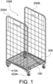
- FIGURES 1 depicts a roll container 1000 featuring two side walls 200, namely a first side wall 200A and a second side wall 200B, on a chassis 100.
- the labels A and B are in this context used to distinguish between two different individual but similar components.
- the side walls 200 may feature, as shown, a conventional design with a peripheral frame delimiting a mesh. Naturally, alternative solid or lighter wall constructions are also foreseeable.
- the side walls 200 are spaced apart from each other in a dimension which is in this context referred to as a transversal dimension which is orthogonal to the main intended travelling dimension of the roll container 1000.
- a removable base 300 is suspended from the lower frame beams of the opposing side walls 200.
- the base 300 has a mesh structure and hooks for suspending the base 300 in a horizontal deployed configuration shown in the FIGURES or in a vertical stored configuration (not illustrated).
- the base is 300 further supported by the chassis 100 from below.
- the roll container 1000 further includes four casters.
- a first rigid caster 410A is attached to the rear end of the first side wall 200A and a second rigid caster 410B is attached to the rear end of a second side wall 200B.
- the other two of the casters provided to a second end of the roll container 1000 which in this context is referred to as the front end, are swivel casters 420, i.e. turning casters.
- a first swivel caster 420A is attached to the front end of the first side wall 200A and a second swivel caster 420B is attached to the front end of a second side wall 200B.
- the caster configuration may be varied by, for example, having only swivel or only rigid casters or any combination thereof.
- the first rigid caster 410A and first swivel caster 420A form a first pair of casters which carries the first side wall 200A.
- the casters 410A, 420A of the first pair of casters are arranged at a distance from one another in the longitudinal dimension of the roll container 1000.
- the second rigid caster 410B and second swivel caster 420B form a second pair of casters which carries the second side wall 200B.
- the casters 410B, 420B of the second pair of casters are arranged at a distance from one another in the longitudinal dimension of the roll container 1000.
- the second side wall 200B is therefore arranged at a distance from the first side wall 200A in the transversal dimension of the roll container 1000.
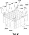
- FIGURE 2 shows the roll container 1000 from below and reveals the design of the chassis 100 which is an H-frame chassis which is a modified version of an A-frame chassis as defined by the standard SFS-EN 12674-1 (Roll containers - Part 1: Terminology, the July 1999 edition).
- Conventional A-frame chassis resembles the letter A in plan view
- an H-frame chassis resembles the letter H in plan view.
- the operating principle of an H-frame chassis roll container 1000 is that in the deployed state (shown in the FIGURES) the side walls 200 extend longitudinally. In the nesting state (not shown in the FIGURES) the side walls 200 are pivoted in respect of a vertical rear hinge so as to turn the front ends of the side walls 200 closer to one another.
- the roll container 1000 includes, on the one hand, a rear hinge, which will be discussed here after, and on the other hand swivel casters 420 which enable movement in respect to the chassis 100.
- the wheel plates 421 of the swivel casters 420 are elongated in the transversal dimension. The wheel plate 421 terminates at the outer end to the side wall 200 and at the inner end to a lip for limiting the movement of the side wall 200 in respect to the chassis 100.
- the front end of the chassis 100 is supported by the wheel plates 421 of the swivel casters 420 so as to allow relative sliding movement between the chassis 100 and the swivel casters 420.
- the swivel caster 420 is fixed to the front end of the side wall 200.
- the wheel plate 421 is fixed to the joint between the front upright and bottom horizontal piece of the frame of the side wall 200.
- the fork 422 of the swivel caster 420 is, in turn, rotatably connected to the plate 421 and houses the wheel 432.
- FIGURE 3 depicts a focused representation of the chassis 100.
- the chassis 100 is to be understood as the stationary components on or to which movable components of the roll container 1000 are fitted.
- the movable components include the side walls 200, the swivel casters 420 and the wheels 412 of the rigid casters 410.
- the chassis 100 includes two arms, namely a first arm 121 and a second arm 122.
- the arms 121, 122 are arranged spaced apart from one another in the transversal dimension.
- the arms 121, 122 are also arranged non-parallel so as to open in a V angle towards the rear of the roll container 1000 so as to facilitate the nesting state when the front ends of the side walls 200 are pivoted towards one another.
- the arms 121, 122 may have, as illustrated, an elongated quadrangular and hollow profile. Alternatively solid arms having a similar or different profile, such as circular, oval, hexagonal. Also, any combinations of hollow and solid profiles having different shapes are foreseeable.
- the arms 121, 122 may be made of metal, such as steel or an aluminium alloy, plastics, composites, etc.
- the arms 121, 122 are connected, preferably on the front half of the arms 121, 122, by a crossmember 110.
- the crossmember 110 is formed to be less resistant to mechanical strain than that of the first and second arm 121, 122. This means that the crossmember 110 is made to more easily elastically deform than the arms 121, 122 or that it is formed as a sacrificial member having lower structural strength than the arms 121, 122 or both. It is preferable that threshold for elastic deformation of the crossmember 110 is set considerably than that of the arms 121, 122 so that the crossmember 110 of the chassis 100 will flex upon impact rather than the arms 121, 122.
- threshold for plastic deformation of the crossmember 110 is set considerably lower than that of the arms 121, 122 so that the crossmember 110 of the chassis 100 will distort or break upon impact rather than the arms 121, 122.
- the difference in mechanical resistance may be established by selecting the material of the crossmember 110 to withstand less stress than that of the arms 121, 122.
- the crossmember 110 may be of, for example, a polymer, such as polyamide, or a composite, such as glass or carbon fibre reinforced polyamide, polyethylene, or polypropylene. The material should, however, preferably withstand impacts enough so as to maintain integrity.
- the crossmember 110 may be made of a thinner profile than the arms 121, 122 to achieve the same result.
- the roll container 1000 is improved in two ways. Firstly, the relatively elastic crossmember 110 will absorb much of the mechanical strain thus minimizing the risk of replacing the arms 121, 122 which may be made from a more expensive material. Secondly, the relatively elastic crossmember 110 will enable flexing of the roll container 1000 on uneven surfaces thus keeping the wheels 412, 422 against the supporting surface. According to a further embodiment, the resistance against flexing in one dimension may be different to resistance in another dimension.
- the crossmember may be made from a composite material having fibres arranged such that flexing may relatively easily occur about one axis and hindered in about another axis.
- the crossmember may flex about an axis extending horizontally in the main travelling direction of the dolly but be prevented about a vertical axis or vice versa. Additionally or alternatively, the design of the crossmember may include additional supports for establishing the same effect.
- the materials and/or mechanical properties of the arms and crossmember may be reversed. More particularly, the crossmember may be made of a relatively sturdy material whereas the arms are made of a sacrificial material flexing and/or breaking more easily than the crossmember.
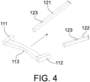
- the crossmember 110 has three sections, namely a first sleeve 111 for receiving the first arm 121, a second sleeve 112 for receiving the second arm 122, and a body 113 connecting the first sleeve 111 to the second sleeve 112.
- the sleeves 111, 112 are therefore aligned with the arms 121, 122 with the body 113 connecting the sleeves 111, 112 in the transversal dimension.
- the sleeves 111, 112 are hollow profiles designed to match that of the arms 111, 112 for receiving the arms 111, 112 in an enclosed manner.
- the crossmember 110 can be repeatedly attached to and detached from the first and second arm 121, 122.
- the attachment can be a simple one as shown in the FIGURES, wherein the arms 121, 122 are simply slid into the sleeves 111, 112 ( FIGURE 4 ).
- connection between the arms 121, 122 and the crossmember 110 is secured.
- the attachment of the arms 121, 122 to the sleeves 111, 112 may be secured by an interlocking coupling interface provided to the crossmember 110, the first arm 121, and to the second arm 122.
- the coupling interface features a female counterpart provided to the first and second arm 121, 122, which counterpart is an opening 123 in the FIGURES.
- a respective male counterpart which may be a protrusion (not shown in the FIGURES) provided to the inner space delimited by the sleeve 111, 112.
- the coupling interface may be reversed by adding a male counterpart on the arms and a receptive female counterpart to the sleeves (not shown in the FIGURES).
- the entire fit between the crossmember 110 and the arms 111, 112 may be reversed by having pins at both ends of the body of the crossmember extending parallel to the arms and having a receptive opening on the arm (not shown in the FIGURES).
- the openings may be provided, for example, to the side surface of the arms that face each other when the chassis is assembled.
- connection between the crossmember 110 and the arms 121, 122 may be further strengthened by a bolt or other detachable fastener (not shown in the FIGURES) in addition to or instead of the interlocking coupling interface.
- the fastener may, for example, penetrate the assembly through the fit between the crossmember and arms.
- the sections of the crossmember 110 may be formed to be integral with the body, wherein the crossmember is a unitary piece, or the sections may be assembled through joints. It is, however, preferable that the crossmember 110 is cast as a unitary piece so as to maintain a continuous structure that provides consistent bending and strength properties.
- the illustrated embodiments show the crossmember 100 forming part of an H-Frame chassis. It would similarly possible to form an A-frame chassis with a somewhat similar construction, with the modification that the arms 121, 122 do not extend through the sleeves 111, 112 as in the embodiment according to the FIGURES.
- the body 133 could be shaped to be slightly convex when viewed from the front.
- the body 113 is shaped concave when viewed from the front.
- the chassis 100 may be disassembled by removing the fit between the crossmember 110 and the arms 121, 122 in a reverse order in respect to assembly.
- the chassis 100 may be easily assembled at the end use location with minimal or no tools and/or competence. This means that the components 110, 121, 122 of the chassis 100 can be shipped to the end use location not attached to each other, which enables efficient packing and thus helps reduce the carbon footprint of the roll container 1000 as compared to a welded structure.
- the crossmember 110 should the crossmember 110 sustain a mechanical failure, it will most likely fail before the arms 121, 122 are damaged. Accordingly, the roll container 1000 may be repaired in situ without shipping the container for welding.
- the same goal of reducing the carbon footprint of the roll container 1000 may be improved additionally or alternatively by considering the hereafter described caster assembly.
- the chassis 100 acts as the mounting point for the rear casters 410 and for hinge points for the side walls 200. Accordingly, the arms 121, 122 are attached at the rear to the rear fork 411 and to a hinge pin 414.
- the rear caster 410 is a rigid caster, i.e. non-turning caster. It is foreseen to construct a similar rear end of the roll container 1000 with a swivel caster, i.e. turning caster, whereby it should be understood that the following description is equally applicable to a swivel caster construction.
- the front caster 420 may be replaced with a rigid caster.
- a swivel caster is, however, preferred at the front of the roll container so as to assist in the pivoting of the side walls about the rear hinges.
- FIGURES 5 to 7 depict a focused representation of the caster assemblies attached to the rear of the chassis 100.
- the caster assemblies may include a rigid caster 410 as shown in the FIGURES or a swivel caster (not shown in the FIGURES).
- the caster assembly is described by showing and referring to a rigid caster even though the same teachings are applicable to swivel casters.
- the interaction between the second arm 122 and the second rigid caster 410B is depicted, but the same teachings are applicable to the interaction between the first arm 121 and the first rigid caster 410A.
- the rigid caster 410 includes a fork 411 which acts as a housing for the wheel 412 which has been omitted from FIGURES 5 and 6 .
- the bottom end of the fork 411 includes an opening for receiving the axle of the wheel 412.
- the fork 411 features a top plate 417.
- the top plate 417 serves the purpose of acting as an attachment point for the arm 122 and hinge pin 414.
- the top plate 417 is preferably planar for receiving and carrying the planar bottom surface of the arm 122.
- the top plate 417 also has a bracket 413 for matching and keeping the therein inserted arm 122 attached to the fork 411.
- the connection between the fork and arm may be another connection which allows axial displacement of the arm in respect to the fork but blocks other degrees of freedom.
- bracket 413 allows for axial displacement of the arm 122 but blocks other degrees of freedom thereof.
- the bracket 413 is therefore a rear sleeve for receiving the arm 122.
- a pin 414 is attached to the fork 411.
- the pin 414 has a dual purpose. Firstly, the pin 414 serves the purpose of forming the male counterpart of a hinge formed between the rear of the chassis 100 and the side wall 200. Secondly, the pin 414 serves the purpose of securing the arm 122 to the fork 411.
- FIGURE 6 best illustrates one exemplary embodiment of the pin 414.
- the pin 414 may have an elongated body extending between a first end and a second end. The body may, for the most part, be cylindrical for promoting rotation around it.
- the first end of the pin 414 has a tip 416 for attachment to the fork 411.
- the tip 416 is shaped to form a first coupling element of an interlocking coupling interface between the pin 414 and the fork 411.
- the second coupling element of the interlocking coupling interface between the pin 414 and the fork 411 may have several alternative manifestations depending on the first coupling element on the tip 414.
- the tip 416 may, for example, have an opening 418 with a male thread as the first coupling element.
- the top plate 417 of the fork 411 on the other hand, may have a corresponding female thread as the second coupling element for attaching the tip 416 to the top plate 417 through tightening rotation.
- the threaded connection may also be reversed with a threaded element protruding from the top plate and interconnecting with a threaded female opening at the end face of the tip (not shown in the FIGURES).
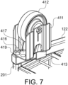
- the opening 418 of the top plate 417 may be blind, wherein the pin 414 is attached to the top plate 417 with a nut 419 provided to the underside of the top plate 417 ( FIGURE 7 ).
- the pin 414 may be secured to the fork 411 in the axial dimension of the pin 414 by a transversal cotter pin extending through a receptive opening at the bottom end of the tip 416 on the underside of the top plate 417 (not shown in the FIGURES).
- the fork 411 and the pin 414 are selected, it is preferable for the fork 411 and the pin 414 to include cooperating coupling elements 419, 416 which form the interlocking coupling interface between the pin 414 and the fork 411.
- the pin 414 blocks also the axial movement of the arm 122 in respect to the fork 411.
- the axial dimension of an element refers to the dimension of greatest extension thereof.
- the rear end of the arm 122 has a through hole 124 which is designed to receive the tip 416 of the pin 414. The pin 414 therefore penetrates the arm 122 and the top plate 417 thus attaching the arm 122 to the fork 411 as illustrated by the dashed line of FIGURE 6 .
- the pin 414 also includes a key 415 for rotating the pin 414 about its axial dimension.
- the key 415 is a shape which enables engagement with a corresponding tool for tightening the pin 414 against a corresponding threaded element which may be a threaded opening 418 or nut 419, for example, on the fork 411.
- the key 415 is located at the second end of the pin 414 opposing the tip 416.
- the key could be arranged somewhere between the first and second end, for example, in the middle of the body in the axial dimension.
- the key 415 exhibits two parallel sides so as to be engaged with a wrench.
- the second end of the pin 414 could feature a screwdriver socket, such as a Philips or torx socket, for engagement with a corresponding screwdriver head.
- both the first and the second arm 121, 122 are attached to the forks 411A, 411B of respective first and second rigid caster assemblies.
- the illustrated embodiment shows the caster assemblies being attached to the rear end of an H-frame chassis.
- first and second side wall 200A, 200B each comprise a hollow vertical profile which is designed to engage with the respective pin 414 on the first and second fork 411A, 411B so as to form the rear hinge of the roll container 1000.
- the rear upright profile of the frame of the side 200 includes a bottom opening through which the pin 414 is inserted upon assembly of the roll container 1000.
- the side wall 200 could feature a separate hinge block attached to the side of the frame profile.
- the end user may assemble or repair the roll container with elementary or no tools. Accordingly, the components of the assembly may be shipped packed efficiently in flat parcels.
- a damaged rear caster for example, can be replaced on site without sending the unit for repair welding. This, in turn, improves the overall volumetric efficiency of the life span of the roll container.
Description
- The present disclosure relates to logistics equipment. In particular, the invention relates to wheeled platforms, i.e. roll containers, on which parceled goods are transported and stored temporarily.
- Roll containers are a popular means of moving and temporary storage of goods. While there are a variety of different types of roll containers, a nesting type has achieved great popularity. The European standard for roll containers EN12674-1:1999 discloses the five main types of nesting roll containers, namely:
- the "A-frame chassis" type,
- the "Z-frame chassis" type,
- the "U-frame chassis" type,
- the "V-frame" type, and
- the "L-frame" type.
- An articulated roll container chassis is known from
EP 0048135 A2 , which discloses a chassis that can be folded between an operational state, in which the chassis resembles the letter M (Fig. 1 ), and a nesting state, in which the chassis resembles the letter V (Fig. 2 ). The chassis has two opposing arms and a cross member welded there between. - The "A-frame chassis" type has gained great popularity. As the name suggests, the type employs an A-shaped chassis in plan view. The "A-frame chassis" type may feature a back frame section with a rear wall extending laterally and integral side pieces, which are known as trombones, extending longitudinally, i.e. orthogonally to the rear wall. The rear castors are attached to the trombones and the front castors are attached to the chassis. "A-frame chassis" roll containers also comprise a liftable base which is hinged to the back frame section of the container. Some "A-frame chassis" models, however, do not feature a rear wall or trombones. In such an open rear configuration, the base may be simply carried by the side walls and the side walls are pivotably attached to the forks of the rear casters. In deployed state, the roll container has a prismatic form. In nesting state, the base is either turned back or to the side towards a vertical orientation or removed and potentially suspended from a side wall. With the base removed from the center, the side walls are then pivoted in and towards each other, wherein the front of the roll container is narrower than the rear. The achieved wedge-shaped is used to nest several roll containers to achieve a compact formation for return logistics. The volumetric efficiency of the roll container, on the other hand, serves the purpose of reducing the carbon footprint of logistics through efficiency in return logistics.
- While the "A-frame chassis" roll container type is very efficient in view of return logistics, there still remains a long standing need to improve to further reduce the carbon footprint of logistics equipment.
- A novel chassis for a roll container is therefore proposed. The chassis features a first arm, a second arm, and a crossmember for connecting the first arm to the second arm so as to form the chassis. The crossmember is engineered to be less resistant to mechanical strain than the first and second arm. The crossmember is such that it can be repeatedly attached to and detached from the first and second arm.
- A roll container is also proposed having such a chassis. The roll container also includes a first pair of casters which are arranged at a distance from one another in the longitudinal dimension of the roll container. A first side wall of the roll container is attached between the first pair of casters. The roll container further includes a second pair of casters which are arranged at a distance from one another in the longitudinal dimension of the roll container. A second side wall of the roll container is attached between the second pair of casters and arranged at a distance from the first side wall in the transversal dimension of the roll container.
- The invention is defined by the features of the independent claims. Some specific embodiments are defined in the dependent claims.
- Considerable benefits are gained with aid of the present proposition. By constructing the crossmember of the chassis as a sacrificial element which can be replaced, the roll container may be repaired easily and, preferably, without the use of tools on the site. Accordingly, damaged chassis does not render the roll container as a recyclable nor does the roll container necessarily need to be transported for welding. This, in turn, improves the overall volumetric efficiency of the life span of the roll container.
- In the following certain exemplary embodiments are described in greater detail with reference to the accompanying drawings, in which:
- FIGURE 1
- illustrates a top perspective view of a roll container according to some embodiments;
- FIGURE 2
- illustrates a detail bottom perspective view of the roll container of
FIGURE 1 ; - FIGURE 3
- illustrates a top elevation view of the chassis of the roll container of
FIGURE 1 , and - FIGURE 4
- illustrates a partial perspective explosion view of the chassis of
FIGURE 3 ; - FIGURE 5
- illustrates a perspective detail view of the rigid wheel caster assembly of the chassis of
FIGURE 3 ; - FIGURE 6
- illustrates an explosion view of the rigid wheel caster assembly of
FIGURE 5 , and - FIGURE 7
- illustrates a detail view of rigid wheel caster assembly of
FIGURE 2 . - First, let us consider the novel construction of the chassis which has been engineered so as to be assembled and disassembled with minimal or no tools and which includes a sacrificial and/or suspending element for improved tolerance for impacts and/or handling.
- The appended FIGURES illustrate one embodiment where an H-
frame roll container 1000 is constructed making use of the novel concept of detachably interconnected components forming parts of thechassis 100. While the concept has been described as applied to an H-frame chassis 100, the same principles are equally applicable to other chassis constructions, chiefly to an A-frame chassis. -
FIGURES 1 depicts aroll container 1000 featuring two side walls 200, namely afirst side wall 200A and asecond side wall 200B, on achassis 100. The labels A and B are in this context used to distinguish between two different individual but similar components. The side walls 200 may feature, as shown, a conventional design with a peripheral frame delimiting a mesh. Naturally, alternative solid or lighter wall constructions are also foreseeable. The side walls 200 are spaced apart from each other in a dimension which is in this context referred to as a transversal dimension which is orthogonal to the main intended travelling dimension of theroll container 1000. Aremovable base 300 is suspended from the lower frame beams of the opposing side walls 200. Thebase 300 has a mesh structure and hooks for suspending the base 300 in a horizontal deployed configuration shown in the FIGURES or in a vertical stored configuration (not illustrated). The base is 300 further supported by thechassis 100 from below. - The
roll container 1000 further includes four casters. Two of the casters provided to a first end of theroll container 1000, which in this context is referred to as the rear end for the sake of clarity, are rigid casters 410, i.e. non-turning casters. A firstrigid caster 410A is attached to the rear end of thefirst side wall 200A and a secondrigid caster 410B is attached to the rear end of asecond side wall 200B. The other two of the casters provided to a second end of theroll container 1000, which in this context is referred to as the front end, are swivel casters 420, i.e. turning casters. Afirst swivel caster 420A is attached to the front end of thefirst side wall 200A and asecond swivel caster 420B is attached to the front end of asecond side wall 200B. The caster configuration may be varied by, for example, having only swivel or only rigid casters or any combination thereof. The firstrigid caster 410A andfirst swivel caster 420A form a first pair of casters which carries thefirst side wall 200A. Thecasters roll container 1000. The secondrigid caster 410B andsecond swivel caster 420B form a second pair of casters which carries thesecond side wall 200B. Thecasters roll container 1000. Thesecond side wall 200B is therefore arranged at a distance from thefirst side wall 200A in the transversal dimension of theroll container 1000. -
FIGURE 2 shows theroll container 1000 from below and reveals the design of thechassis 100 which is an H-frame chassis which is a modified version of an A-frame chassis as defined by the standard SFS-EN 12674-1 (Roll containers - Part 1: Terminology, the July 1999 edition). Conventional A-frame chassis resembles the letter A in plan view, whereas an H-frame chassis resembles the letter H in plan view. The operating principle of an H-framechassis roll container 1000 is that in the deployed state (shown in the FIGURES) the side walls 200 extend longitudinally. In the nesting state (not shown in the FIGURES) the side walls 200 are pivoted in respect of a vertical rear hinge so as to turn the front ends of the side walls 200 closer to one another. Such pivoted the side walls 200 form a V shape when viewed from above. This requires removal or turning of the base 300 into a vertical orientation. To achieve the nesting option, theroll container 1000 includes, on the one hand, a rear hinge, which will be discussed here after, and on the other hand swivel casters 420 which enable movement in respect to thechassis 100. As shown inFIGURE 2 , the wheel plates 421 of the swivel casters 420 are elongated in the transversal dimension. The wheel plate 421 terminates at the outer end to the side wall 200 and at the inner end to a lip for limiting the movement of the side wall 200 in respect to thechassis 100. Accordingly, the front end of thechassis 100 is supported by the wheel plates 421 of the swivel casters 420 so as to allow relative sliding movement between thechassis 100 and the swivel casters 420. The swivel caster 420 is fixed to the front end of the side wall 200. In the shown example the wheel plate 421 is fixed to the joint between the front upright and bottom horizontal piece of the frame of the side wall 200. The fork 422 of the swivel caster 420 is, in turn, rotatably connected to the plate 421 and houses the wheel 432. -
FIGURE 3 depicts a focused representation of thechassis 100. Thechassis 100 is to be understood as the stationary components on or to which movable components of theroll container 1000 are fitted. In the illustrated example, the movable components include the side walls 200, the swivel casters 420 and thewheels 412 of the rigid casters 410. Thechassis 100 includes two arms, namely afirst arm 121 and asecond arm 122. Thearms arms roll container 1000 so as to facilitate the nesting state when the front ends of the side walls 200 are pivoted towards one another. Thearms arms - The
arms arms crossmember 110. Thecrossmember 110 is formed to be less resistant to mechanical strain than that of the first andsecond arm crossmember 110 is made to more easily elastically deform than thearms arms crossmember 110 is set considerably than that of thearms crossmember 110 of thechassis 100 will flex upon impact rather than thearms crossmember 110 is set considerably lower than that of thearms crossmember 110 of thechassis 100 will distort or break upon impact rather than thearms crossmember 110 to withstand less stress than that of thearms crossmember 110 may be of, for example, a polymer, such as polyamide, or a composite, such as glass or carbon fibre reinforced polyamide, polyethylene, or polypropylene. The material should, however, preferably withstand impacts enough so as to maintain integrity. Alternatively or additionally, thecrossmember 110 may be made of a thinner profile than thearms crossmember 110 made more elastic than thearms roll container 1000 is improved in two ways. Firstly, the relativelyelastic crossmember 110 will absorb much of the mechanical strain thus minimizing the risk of replacing thearms elastic crossmember 110 will enable flexing of theroll container 1000 on uneven surfaces thus keeping thewheels 412, 422 against the supporting surface. According to a further embodiment, the resistance against flexing in one dimension may be different to resistance in another dimension. For example, the crossmember may be made from a composite material having fibres arranged such that flexing may relatively easily occur about one axis and hindered in about another axis. This means that the crossmember may flex about an axis extending horizontally in the main travelling direction of the dolly but be prevented about a vertical axis or vice versa. Additionally or alternatively, the design of the crossmember may include additional supports for establishing the same effect. - In an example which is not according to the present invention, the materials and/or mechanical properties of the arms and crossmember may be reversed. More particularly, the crossmember may be made of a relatively sturdy material whereas the arms are made of a sacrificial material flexing and/or breaking more easily than the crossmember.
- The
crossmember 110 has three sections, namely afirst sleeve 111 for receiving thefirst arm 121, asecond sleeve 112 for receiving thesecond arm 122, and abody 113 connecting thefirst sleeve 111 to thesecond sleeve 112. Thesleeves arms body 113 connecting thesleeves sleeves arms arms sleeves arms crossmember 110 can be repeatedly attached to and detached from the first andsecond arm arms sleeves 111, 112 (FIGURE 4 ). - When the
chassis 100 is assembled, it rides at the rear on the rigid casters 410 and at the front on the plate 421 of the swivel casters 420. To maintain rigidity, it is preferred that connection between thearms crossmember 110 is secured. The attachment of thearms sleeves crossmember 110, thefirst arm 121, and to thesecond arm 122. The coupling interface features a female counterpart provided to the first andsecond arm opening 123 in the FIGURES. Cooperating with the female counterpart is a respective male counterpart which may be a protrusion (not shown in the FIGURES) provided to the inner space delimited by thesleeve crossmember 110 and thearms crossmember 110 and thearms - The sections of the
crossmember 110, whether female (as shown) or male (as not shown), may be formed to be integral with the body, wherein the crossmember is a unitary piece, or the sections may be assembled through joints. It is, however, preferable that thecrossmember 110 is cast as a unitary piece so as to maintain a continuous structure that provides consistent bending and strength properties. - The illustrated embodiments show the
crossmember 100 forming part of an H-Frame chassis. It would similarly possible to form an A-frame chassis with a somewhat similar construction, with the modification that thearms sleeves body 113 is shaped concave when viewed from the front. - The
chassis 100 may be disassembled by removing the fit between thecrossmember 110 and thearms crossmember 110 to the first andsecond arm chassis 100 may be easily assembled at the end use location with minimal or no tools and/or competence. This means that thecomponents chassis 100 can be shipped to the end use location not attached to each other, which enables efficient packing and thus helps reduce the carbon footprint of theroll container 1000 as compared to a welded structure. In addition, should thecrossmember 110 sustain a mechanical failure, it will most likely fail before thearms roll container 1000 may be repaired in situ without shipping the container for welding. - The same goal of reducing the carbon footprint of the
roll container 1000 may be improved additionally or alternatively by considering the hereafter described caster assembly. - At the rear the
chassis 100 acts as the mounting point for the rear casters 410 and for hinge points for the side walls 200. Accordingly, thearms rear fork 411 and to ahinge pin 414. In the illustrated embodiment, the rear caster 410 is a rigid caster, i.e. non-turning caster. It is foreseen to construct a similar rear end of theroll container 1000 with a swivel caster, i.e. turning caster, whereby it should be understood that the following description is equally applicable to a swivel caster construction. Additionally or alternatively, the front caster 420 may be replaced with a rigid caster. A swivel caster is, however, preferred at the front of the roll container so as to assist in the pivoting of the side walls about the rear hinges. -
FIGURES 5 to 7 depict a focused representation of the caster assemblies attached to the rear of thechassis 100. The caster assemblies may include a rigid caster 410 as shown in the FIGURES or a swivel caster (not shown in the FIGURES). For illustrative purposes, the caster assembly is described by showing and referring to a rigid caster even though the same teachings are applicable to swivel casters. Similarly, for illustrative purposes, the interaction between thesecond arm 122 and the secondrigid caster 410B is depicted, but the same teachings are applicable to the interaction between thefirst arm 121 and the firstrigid caster 410A. - The rigid caster 410 includes a
fork 411 which acts as a housing for thewheel 412 which has been omitted fromFIGURES 5 and6 . The bottom end of thefork 411 includes an opening for receiving the axle of thewheel 412. Thefork 411 features atop plate 417. Thetop plate 417 serves the purpose of acting as an attachment point for thearm 122 andhinge pin 414. Thetop plate 417 is preferably planar for receiving and carrying the planar bottom surface of thearm 122. Thetop plate 417 also has abracket 413 for matching and keeping the therein insertedarm 122 attached to thefork 411. Alternatively the connection between the fork and arm may be another connection which allows axial displacement of the arm in respect to the fork but blocks other degrees of freedom. Such alternatives include fishtail and other positively locking shapes (not shown in the FIGURES). Preferably, thebracket 413 allows for axial displacement of thearm 122 but blocks other degrees of freedom thereof. Thebracket 413 is therefore a rear sleeve for receiving thearm 122. - A
pin 414 is attached to thefork 411. In the illustrated embodiment, thepin 414 has a dual purpose. Firstly, thepin 414 serves the purpose of forming the male counterpart of a hinge formed between the rear of thechassis 100 and the side wall 200. Secondly, thepin 414 serves the purpose of securing thearm 122 to thefork 411.FIGURE 6 best illustrates one exemplary embodiment of thepin 414. Thepin 414 may have an elongated body extending between a first end and a second end. The body may, for the most part, be cylindrical for promoting rotation around it. - The first end of the
pin 414 has atip 416 for attachment to thefork 411. Thetip 416 is shaped to form a first coupling element of an interlocking coupling interface between thepin 414 and thefork 411. The second coupling element of the interlocking coupling interface between thepin 414 and thefork 411 may have several alternative manifestations depending on the first coupling element on thetip 414. Thetip 416 may, for example, have anopening 418 with a male thread as the first coupling element. Thetop plate 417 of thefork 411, on the other hand, may have a corresponding female thread as the second coupling element for attaching thetip 416 to thetop plate 417 through tightening rotation. The threaded connection may also be reversed with a threaded element protruding from the top plate and interconnecting with a threaded female opening at the end face of the tip (not shown in the FIGURES). Alternatively, as shown in the FIGURES, theopening 418 of thetop plate 417 may be blind, wherein thepin 414 is attached to thetop plate 417 with anut 419 provided to the underside of the top plate 417 (FIGURE 7 ). Alternatively, thepin 414 may be secured to thefork 411 in the axial dimension of thepin 414 by a transversal cotter pin extending through a receptive opening at the bottom end of thetip 416 on the underside of the top plate 417 (not shown in the FIGURES). Regardless of which of the disclosed or undisclosed interconnecting elements are selected, it is preferable for thefork 411 and thepin 414 to include cooperatingcoupling elements pin 414 and thefork 411. - As indicated above, the
pin 414 blocks also the axial movement of thearm 122 in respect to thefork 411. In this context, the axial dimension of an element, such as thepin 414 orarm 122, refers to the dimension of greatest extension thereof. The rear end of thearm 122 has a throughhole 124 which is designed to receive thetip 416 of thepin 414. Thepin 414 therefore penetrates thearm 122 and thetop plate 417 thus attaching thearm 122 to thefork 411 as illustrated by the dashed line ofFIGURE 6 . - The
pin 414 also includes a key 415 for rotating thepin 414 about its axial dimension. The key 415 is a shape which enables engagement with a corresponding tool for tightening thepin 414 against a corresponding threaded element which may be a threadedopening 418 ornut 419, for example, on thefork 411. According to the shown embodiment, the key 415 is located at the second end of thepin 414 opposing thetip 416. Alternatively, the key could be arranged somewhere between the first and second end, for example, in the middle of the body in the axial dimension. The key 415 exhibits two parallel sides so as to be engaged with a wrench. Alternatively, the second end of thepin 414 could feature a screwdriver socket, such as a Philips or torx socket, for engagement with a corresponding screwdriver head. - Returning the illustration of the
chassis 100 shown byFIGURE 3 it can be stated that both the first and thesecond arm forks - In addition to the
pin 414 acting as a fastener for fastening thearms forks side walls second side wall respective pin 414 on the first andsecond fork roll container 1000. In the illustrated example, the rear upright profile of the frame of the side 200 includes a bottom opening through which thepin 414 is inserted upon assembly of theroll container 1000. Alternatively, the side wall 200 could feature a separate hinge block attached to the side of the frame profile. - With the proposed modular caster assembly the end user may assemble or repair the roll container with elementary or no tools. Accordingly, the components of the assembly may be shipped packed efficiently in flat parcels. On the other hand, by assembling the caster assembly with repeatedly attached joints, a damaged rear caster, for example, can be replaced on site without sending the unit for repair welding. This, in turn, improves the overall volumetric efficiency of the life span of the roll container.
-
No. Element No. Element 100 chassis 411 fork 110 crossmember 412 wheel 111 first sleeve 413 bracket 112 second sleeve 414 pin 113 body 415 key 121 first arm 416 tip 122 second arm 417 top plate 123 slot 418 hole 124 hole 419 nut 200 side wall 420 swivel caster 201 vertical profile 421 wheel plate 300 base 422 fork 410 rigid caster 423 wheel
Claims (13)
- A chassis (100) for a roll container (1000), the chassis (100) comprising:- a first arm (121),- a second arm (122), and- a crossmember (110) configured to connect the first arm (121) to the second arm (122) so as to form a chassis (100), wherein the crossmember (110) is configured to be repeatedly attached to and detached from the first and second arm (121, 122),characterized in that the crossmember (110) is formed to be less resistant to mechanical strain than the first and second arm (121, 122)
- The chassis (100) according to claim 1, wherein the crossmember (110) is formed of a material which is less resistant to mechanical strain than that of the first and second arm (121, 122).
- The chassis (100) according to claim 1 or 2, wherein the crossmember (110) is made of a polymer, particularly polyamide or a composite material.
- The chassis (100) according to any one of the preceding claims, wherein the crossmember (110) is cast as a unitary piece.
- The chassis (100) according to any one of the preceding claims, wherein the first and second arm (121, 122) are made of metal.
- The chassis (100) according to any one of the preceding claims, wherein the crossmember (110) comprises:- a first sleeve (111) for receiving the first arm (121),- a second sleeve (112) for receiving the second arm (122), and- a body (113) connecting the first sleeve (111) to the second sleeve (112).
- The chassis (100) according to claim 6, wherein the crossmember (110) is configured to be attached to the first and second arm (121, 122) through an interlocking coupling interface provided to the crossmember (110), the first arm (121), and to the second arm (122).
- The chassis (100) according to claim 7, wherein the interlocking coupling interface comprises a female counterpart provided to the first and second arm (121, 122).
- The chassis (100) according to claim 8, wherein the female counterpart is an opening (123).
- The chassis (100) according to claim 7, 8, or 9, wherein the interlocking coupling interface comprises a male counterpart provided to the crossmember (110).
- The chassis (100) according to claim 10, wherein the male counterpart is provided to the first or second sleeve (121, 122) or both.
- The chassis (100) according to any one of the preceding claims, wherein the crossmember (110) is configured to connect the first arm (121) to the second arm (122) so as to form an A-frame or an H-frame chassis (100).
- A roll container (1000) comprising:- a first pair of casters (410A, 420A) arranged at a distance from one another in the longitudinal dimension of the roll container (1000),- a first side wall (200A) attached between the first pair of casters (410A, 420A),- a second pair of casters (410B, 420B) arranged at a distance from one another in the longitudinal dimension of the roll container (1000), and- a second side wall (200B) attached between the second pair of casters (410B, 420B) and arranged at a distance from the first side wall (200A) in the transversal dimension of the roll container (1000),characterized by a chassis (100) according to any one of the preceding claims connecting the casters (410A, 420A, 410B, 420B) to each other.
Applications Claiming Priority (2)
| Application Number | Priority Date | Filing Date | Title |
|---|---|---|---|
| FI20185266A FI129266B (en) | 2018-03-21 | 2018-03-21 | Chassis for a roll container and a roll container comprising the same |
| PCT/FI2019/050217 WO2019180313A1 (en) | 2018-03-21 | 2019-03-14 | Chassis for a roll container and a roll container comprising the same |
Publications (4)
| Publication Number | Publication Date |
|---|---|
| EP3768572A1 EP3768572A1 (en) | 2021-01-27 |
| EP3768572A4 EP3768572A4 (en) | 2021-12-01 |
| EP3768572B1 true EP3768572B1 (en) | 2023-08-09 |
| EP3768572C0 EP3768572C0 (en) | 2023-08-09 |
Family
ID=67986038
Family Applications (1)
| Application Number | Title | Priority Date | Filing Date |
|---|---|---|---|
| EP19771076.7A Active EP3768572B1 (en) | 2018-03-21 | 2019-03-14 | Chassis for a roll container and a roll container comprising the same |
Country Status (6)
| Country | Link |
|---|---|
| US (1) | US11498599B2 (en) |
| EP (1) | EP3768572B1 (en) |
| CN (1) | CN111936368B (en) |
| AU (1) | AU2019239820B2 (en) |
| FI (1) | FI129266B (en) |
| WO (1) | WO2019180313A1 (en) |
Families Citing this family (4)
| Publication number | Priority date | Publication date | Assignee | Title |
|---|---|---|---|---|
| AU201815186S (en) * | 2018-03-01 | 2018-10-02 | Container Centralen As | Wheel fork for dollies [wheeled platforms] |
| FI129266B (en) * | 2018-03-21 | 2021-10-29 | Hartwall K Oy Ab | Chassis for a roll container and a roll container comprising the same |
| CN110758507B (en) * | 2019-12-10 | 2021-12-14 | 安徽浦进轨道装备有限公司 | Small trolley convenient to fold for rail high-speed rail |
| JP7297029B2 (en) * | 2021-07-02 | 2023-06-23 | グリーン プラス カンパニー,リミテッド | foldable lightweight roll container |
Family Cites Families (37)
| Publication number | Priority date | Publication date | Assignee | Title |
|---|---|---|---|---|
| US2774609A (en) * | 1954-01-04 | 1956-12-18 | Raymond C Winger | Dolly with disassembly facilitating means |
| FR2159008A5 (en) * | 1971-10-29 | 1973-06-15 | Rigulag Ab & Co | |
| SE369066B (en) * | 1972-11-10 | 1974-08-05 | Rigulag Ab & Co | |
| US4060271A (en) * | 1976-03-23 | 1977-11-29 | Williams Joseph J | Wheelchair hold down assembly |
| US4199164A (en) * | 1976-09-23 | 1980-04-22 | Sjoblom Ake E | Nestable roller pallet |
| DE3010366A1 (en) * | 1979-04-09 | 1980-10-23 | Campisusa Spa | ROLLER CONTAINERS WITH SWIVELING SIDEWALLS AND WITH THE SWIVELING ROLLERS CARRYED IN THE AREA OF THE SWIVELING ENDS |
| US4363495A (en) * | 1979-08-20 | 1982-12-14 | Henson Kenneth A | Sloping-terrain vehicle |
| US4456273A (en) * | 1980-09-12 | 1984-06-26 | Mckinnon Crerand | Load-carrying trolleys |
| US5330064A (en) * | 1993-04-29 | 1994-07-19 | Hall Donald M | Support assembly for a holding rack |
| US5564720A (en) * | 1994-07-13 | 1996-10-15 | Stringer; Russell L. | Portable game cart |
| FI2836U1 (en) * | 1996-12-05 | 1997-04-22 | Merikiito Ab Oy | transport Hedge |
| DE19849843A1 (en) | 1998-10-29 | 2000-05-04 | Wanzl Metallwarenfabrik Kg | Driving frame |
| US20030127815A1 (en) * | 2002-01-10 | 2003-07-10 | Hall Donald M. | Wheeled vehicles, racks, casters for vehicles, and wheel and frame construction |
| CA2381886A1 (en) * | 2002-04-17 | 2003-10-17 | Patrick Murray | Nesting rack |
| US20040239060A1 (en) * | 2003-05-27 | 2004-12-02 | Martin Faucher | Steerable person handling system |
| US20050275178A1 (en) * | 2004-06-10 | 2005-12-15 | Douglas Huesdash | Mobile modular stand |
| DE102006024926A1 (en) * | 2006-05-25 | 2007-11-29 | Mierswa, Aurélien | Glass fiber or carbon fiber winter sports sledge has two side frames linked to seat by pivot points |
| US8181975B2 (en) * | 2009-02-10 | 2012-05-22 | Sarbjit Parhar | Scooter vehicle system |
| GB2484550A (en) * | 2010-10-15 | 2012-04-18 | Hartwall K Oy Ab | A nesting roll container with welded joints |
| US8950760B1 (en) * | 2010-12-23 | 2015-02-10 | Steven S. Davis | Three wheeled automotive dolly and method of use |
| US8651501B1 (en) * | 2010-12-23 | 2014-02-18 | Steven Davis | Three wheeled automotive dolly |
| EP2597011A1 (en) | 2011-11-25 | 2013-05-29 | K. Hartwall Oy AB | Nesting roll container, buffer element therefor, and method of transporting a plurality nesting roll containers in a queue formation |
| US9010798B2 (en) * | 2012-07-23 | 2015-04-21 | Luca Buttazzoni | Self-contained dolly assembly |
| CN203593018U (en) * | 2013-10-09 | 2014-05-14 | 青岛中瑞物流器械有限公司 | Logistics vehicle |
| CN203713930U (en) * | 2013-12-16 | 2014-07-16 | 睿志达光电(深圳)有限公司 | Dustproof material trolley |
| CN205730062U (en) * | 2016-06-12 | 2016-11-30 | 金俊 | A kind of handbarrow for fire rescue equipments transport |
| FI128393B (en) * | 2018-03-21 | 2020-04-15 | Hartwall K Oy Ab | A caster assembly, a chassis comprising such an assembly, and a roll container comprising such a chassis |
| FI129266B (en) * | 2018-03-21 | 2021-10-29 | Hartwall K Oy Ab | Chassis for a roll container and a roll container comprising the same |
| GB201805112D0 (en) * | 2018-03-28 | 2018-05-09 | Rollapole Ltd | An improved transportation apparatus |
| US10351155B1 (en) * | 2018-05-03 | 2019-07-16 | Suncast Technologies, Llc | Laundry cart |
| US20200130719A1 (en) * | 2018-10-31 | 2020-04-30 | Michael J. SAELI | Adjustable transport cart |
| CN209535151U (en) * | 2019-01-19 | 2019-10-25 | 广东伟经日用五金制品有限公司 | A kind of buckle-type combination cart |
| US10752275B1 (en) * | 2019-04-12 | 2020-08-25 | Meng-I Sung | Panel cart |
| US10912686B2 (en) * | 2019-05-02 | 2021-02-09 | Pearce J. Pierce | Wheelchair dolly |
| US11091182B1 (en) * | 2019-07-22 | 2021-08-17 | Amazon Technologies, Inc. | Multi-surface cart |
| JP7285164B2 (en) * | 2019-08-08 | 2023-06-01 | 株式会社マキタ | wheelbarrow |
| KR102297086B1 (en) * | 2020-05-20 | 2021-09-02 | 주식회사 브랜뉴인터내셔널 | Baby carriage with improved ease of use |
-
2018
- 2018-03-21 FI FI20185266A patent/FI129266B/en active IP Right Grant
-
2019
- 2019-03-14 CN CN201980020588.8A patent/CN111936368B/en active Active
- 2019-03-14 WO PCT/FI2019/050217 patent/WO2019180313A1/en unknown
- 2019-03-14 EP EP19771076.7A patent/EP3768572B1/en active Active
- 2019-03-14 US US16/982,860 patent/US11498599B2/en active Active
- 2019-03-14 AU AU2019239820A patent/AU2019239820B2/en active Active
Also Published As
| Publication number | Publication date |
|---|---|
| FI20185266A1 (en) | 2019-09-22 |
| EP3768572A4 (en) | 2021-12-01 |
| US20210053601A1 (en) | 2021-02-25 |
| EP3768572A1 (en) | 2021-01-27 |
| AU2019239820B2 (en) | 2021-08-12 |
| CN111936368B (en) | 2022-10-28 |
| EP3768572C0 (en) | 2023-08-09 |
| WO2019180313A1 (en) | 2019-09-26 |
| FI129266B (en) | 2021-10-29 |
| CN111936368A (en) | 2020-11-13 |
| US11498599B2 (en) | 2022-11-15 |
| AU2019239820A1 (en) | 2020-09-24 |
Similar Documents
| Publication | Publication Date | Title |
|---|---|---|
| EP3768572B1 (en) | Chassis for a roll container and a roll container comprising the same | |
| AU2019239822B2 (en) | A caster assembly, a chassis comprising such an assembly, and a roll container comprising such a chassis | |
| US20190387892A1 (en) | Connectors for collapsible bed frame and collapsible bed frame having same | |
| US6502280B2 (en) | Lightweight high capacity industrial caster | |
| US6923456B2 (en) | Shopping cart having caster lift | |
| CN103124686B (en) | Materials handling vehicle, for its overhanging support assembly and correlation technique | |
| US6540241B2 (en) | Handcart | |
| JP3223834U (en) | dolly | |
| US20040056465A1 (en) | Stabilizer pad for vehicles | |
| US7946598B1 (en) | Hand cart having one piece plastic frame useful as a two wheel hand cart and four wheel configuration and method of manufacturing same | |
| US7699576B2 (en) | Tire lifting and mounting tool | |
| CA2475999A1 (en) | Base leg for lift truck | |
| US7267368B2 (en) | Stabilizer pad for vehicles | |
| CN111747349A (en) | Modular fork carriage assembly for materials handling vehicle | |
| CN211003039U (en) | Combined equipment carrying set | |
| KR950002933Y1 (en) | The structure of hand car | |
| US6240997B1 (en) | Rolling steel door | |
| US20240034377A1 (en) | Hand truck assembly and related devices and methods | |
| US10233612B2 (en) | Tractor attachment and tractor attachment kit | |
| CN216269462U (en) | Hopper frame connecting structure for handcart | |
| EP1601560B1 (en) | Stabilizer pad for vehicles | |
| WO2020263221A1 (en) | Modular gondola moving systems and methods | |
| MXPA05008684A (en) | Foldable, moveable and portable bed useful for industrial and mechanic-automotive works. | |
| JPH09249130A (en) | Carriage | |
| EP1360952A1 (en) | Wheelchair |
Legal Events
| Date | Code | Title | Description |
|---|---|---|---|
| STAA | Information on the status of an ep patent application or granted ep patent |
Free format text: STATUS: THE INTERNATIONAL PUBLICATION HAS BEEN MADE |
|
| PUAI | Public reference made under article 153(3) epc to a published international application that has entered the european phase |
Free format text: ORIGINAL CODE: 0009012 |
|
| STAA | Information on the status of an ep patent application or granted ep patent |
Free format text: STATUS: REQUEST FOR EXAMINATION WAS MADE |
|
| 17P | Request for examination filed |
Effective date: 20200826 |
|
| AK | Designated contracting states |
Kind code of ref document: A1 Designated state(s): AL AT BE BG CH CY CZ DE DK EE ES FI FR GB GR HR HU IE IS IT LI LT LU LV MC MK MT NL NO PL PT RO RS SE SI SK SM TR |
|
| AX | Request for extension of the european patent |
Extension state: BA ME |
|
| DAV | Request for validation of the european patent (deleted) | ||
| DAX | Request for extension of the european patent (deleted) | ||
| A4 | Supplementary search report drawn up and despatched |
Effective date: 20211102 |
|
| RIC1 | Information provided on ipc code assigned before grant |
Ipc: B62B 3/00 20060101ALI20211026BHEP Ipc: B62B 3/02 20060101AFI20211026BHEP |
|
| GRAP | Despatch of communication of intention to grant a patent |
Free format text: ORIGINAL CODE: EPIDOSNIGR1 |
|
| STAA | Information on the status of an ep patent application or granted ep patent |
Free format text: STATUS: GRANT OF PATENT IS INTENDED |
|
| INTG | Intention to grant announced |
Effective date: 20230509 |
|
| GRAS | Grant fee paid |
Free format text: ORIGINAL CODE: EPIDOSNIGR3 |
|
| GRAA | (expected) grant |
Free format text: ORIGINAL CODE: 0009210 |
|
| STAA | Information on the status of an ep patent application or granted ep patent |
Free format text: STATUS: THE PATENT HAS BEEN GRANTED |
|
| AK | Designated contracting states |
Kind code of ref document: B1 Designated state(s): AL AT BE BG CH CY CZ DE DK EE ES FI FR GB GR HR HU IE IS IT LI LT LU LV MC MK MT NL NO PL PT RO RS SE SI SK SM TR |
|
| REG | Reference to a national code |
Ref country code: GB Ref legal event code: FG4D |
|
| REG | Reference to a national code |
Ref country code: CH Ref legal event code: EP |
|
| REG | Reference to a national code |
Ref country code: IE Ref legal event code: FG4D |
|
| REG | Reference to a national code |
Ref country code: DE Ref legal event code: R096 Ref document number: 602019034658 Country of ref document: DE |
|
| U01 | Request for unitary effect filed |
Effective date: 20230815 |
|
| U07 | Unitary effect registered |
Designated state(s): AT BE BG DE DK EE FI FR IT LT LU LV MT NL PT SE SI Effective date: 20230821 |
|
| PG25 | Lapsed in a contracting state [announced via postgrant information from national office to epo] |
Ref country code: GR Free format text: LAPSE BECAUSE OF FAILURE TO SUBMIT A TRANSLATION OF THE DESCRIPTION OR TO PAY THE FEE WITHIN THE PRESCRIBED TIME-LIMIT Effective date: 20231110 |
|
| PG25 | Lapsed in a contracting state [announced via postgrant information from national office to epo] |
Ref country code: IS Free format text: LAPSE BECAUSE OF FAILURE TO SUBMIT A TRANSLATION OF THE DESCRIPTION OR TO PAY THE FEE WITHIN THE PRESCRIBED TIME-LIMIT Effective date: 20231209 |
|
| PG25 | Lapsed in a contracting state [announced via postgrant information from national office to epo] |
Ref country code: RS Free format text: LAPSE BECAUSE OF FAILURE TO SUBMIT A TRANSLATION OF THE DESCRIPTION OR TO PAY THE FEE WITHIN THE PRESCRIBED TIME-LIMIT Effective date: 20230809 Ref country code: NO Free format text: LAPSE BECAUSE OF FAILURE TO SUBMIT A TRANSLATION OF THE DESCRIPTION OR TO PAY THE FEE WITHIN THE PRESCRIBED TIME-LIMIT Effective date: 20231109 Ref country code: IS Free format text: LAPSE BECAUSE OF FAILURE TO SUBMIT A TRANSLATION OF THE DESCRIPTION OR TO PAY THE FEE WITHIN THE PRESCRIBED TIME-LIMIT Effective date: 20231209 Ref country code: HR Free format text: LAPSE BECAUSE OF FAILURE TO SUBMIT A TRANSLATION OF THE DESCRIPTION OR TO PAY THE FEE WITHIN THE PRESCRIBED TIME-LIMIT Effective date: 20230809 Ref country code: GR Free format text: LAPSE BECAUSE OF FAILURE TO SUBMIT A TRANSLATION OF THE DESCRIPTION OR TO PAY THE FEE WITHIN THE PRESCRIBED TIME-LIMIT Effective date: 20231110 |
|
| PG25 | Lapsed in a contracting state [announced via postgrant information from national office to epo] |
Ref country code: PL Free format text: LAPSE BECAUSE OF FAILURE TO SUBMIT A TRANSLATION OF THE DESCRIPTION OR TO PAY THE FEE WITHIN THE PRESCRIBED TIME-LIMIT Effective date: 20230809 |
|
| U20 | Renewal fee paid [unitary effect] |
Year of fee payment: 6 Effective date: 20240301 |