EP3768540B1 - Dispositif de ventilation d'un véhicule automobile - Google Patents
Dispositif de ventilation d'un véhicule automobile Download PDFInfo
- Publication number
- EP3768540B1 EP3768540B1 EP19790041.8A EP19790041A EP3768540B1 EP 3768540 B1 EP3768540 B1 EP 3768540B1 EP 19790041 A EP19790041 A EP 19790041A EP 3768540 B1 EP3768540 B1 EP 3768540B1
- Authority
- EP
- European Patent Office
- Prior art keywords
- shield
- turbulence
- motor
- air
- arm
- Prior art date
- Legal status (The legal status is an assumption and is not a legal conclusion. Google has not performed a legal analysis and makes no representation as to the accuracy of the status listed.)
- Active
Links
Images


Classifications
-
- B—PERFORMING OPERATIONS; TRANSPORTING
- B60—VEHICLES IN GENERAL
- B60K—ARRANGEMENT OR MOUNTING OF PROPULSION UNITS OR OF TRANSMISSIONS IN VEHICLES; ARRANGEMENT OR MOUNTING OF PLURAL DIVERSE PRIME-MOVERS IN VEHICLES; AUXILIARY DRIVES FOR VEHICLES; INSTRUMENTATION OR DASHBOARDS FOR VEHICLES; ARRANGEMENTS IN CONNECTION WITH COOLING, AIR INTAKE, GAS EXHAUST OR FUEL SUPPLY OF PROPULSION UNITS IN VEHICLES
- B60K11/00—Arrangement in connection with cooling of propulsion units
- B60K11/02—Arrangement in connection with cooling of propulsion units with liquid cooling
- B60K11/04—Arrangement or mounting of radiators, radiator shutters, or radiator blinds
-
- B—PERFORMING OPERATIONS; TRANSPORTING
- B60—VEHICLES IN GENERAL
- B60K—ARRANGEMENT OR MOUNTING OF PROPULSION UNITS OR OF TRANSMISSIONS IN VEHICLES; ARRANGEMENT OR MOUNTING OF PLURAL DIVERSE PRIME-MOVERS IN VEHICLES; AUXILIARY DRIVES FOR VEHICLES; INSTRUMENTATION OR DASHBOARDS FOR VEHICLES; ARRANGEMENTS IN CONNECTION WITH COOLING, AIR INTAKE, GAS EXHAUST OR FUEL SUPPLY OF PROPULSION UNITS IN VEHICLES
- B60K11/00—Arrangement in connection with cooling of propulsion units
- B60K11/08—Air inlets for cooling; Shutters or blinds therefor
-
- B—PERFORMING OPERATIONS; TRANSPORTING
- B60—VEHICLES IN GENERAL
- B60Y—INDEXING SCHEME RELATING TO ASPECTS CROSS-CUTTING VEHICLE TECHNOLOGY
- B60Y2306/00—Other features of vehicle sub-units
- B60Y2306/09—Reducing noise
Definitions
- the present invention relates to the field of cooling of motor vehicle engines, in particular relates to a ventilation device for a motor vehicle.
- a motor vehicle is commonly equipped with cooling systems located in its engine compartment.
- the heat engine is thus cooled by a supply of external air. This outside air makes it possible to cool, via heat exchangers, a fluid also circulating in a thermal loop of the vehicle.
- cooling systems also called “cooling units” most often include at least one exterior air inlet port generally located on the body of the vehicle, and for example at the front of the vehicle, one or several heat exchangers arranged on the path of the incoming air as well as a motorized fan unit making it possible to force the air in, for example when the vehicle is stationary.
- each of the components of these cooling units is predetermined and must be respected in order to ensure the proper functioning of these cooling units.
- the motor-fan unit must be placed at a distance sufficiently far from the heat exchangers in order to optimize the operation of the latter.
- the tonal noise or harmonic noise generated by the forced circulation of air is undesirable for the passengers of the motor vehicle. These noises may be heard outside or inside the vehicle.
- This noise is notably due to fan blades stirring air too close to the arms which carry the motor-fan unit.
- the noise level depends in particular on the speed of the air flow and the distance between the blades and the arms.
- the frequency of the noise depends in particular on the number of arms.
- the invention makes it possible to reduce noise, in particular tonal noise, without having to modify the other performances of the ventilation device.
- noise is generated by turbulence, particularly around the arm(s)
- reducing turbulence helps reduce noise.
- the number of arms can for example be less than or equal to 6.
- the anti-turbulence shield is placed in the air passage at a location chosen so as to prevent turbulence from forming, this turbulence would then be, if it were not prevented, among those of greater amplitudes in this air passage.
- These zones also correspond to areas of high air flow speeds.
- the shield(s) occupy a total surface area of less than 20%, or even less than 10%, or even 5%, of the total surface area of the air passage, so as not to affect the performance of the ventilation device.
- the ventilation device comprising a motor-fan unit support, this support comprising at least one mechanical holding arm of the motor, the shield is arranged to prevent turbulence from forming on contact of this arm.
- the anti-turbulence shield is formed on the motor-fan unit support.
- the anti-turbulence shield is attached, then fixed for example by snap-fastening or force mounting, on the motor-fan unit support.
- the anti-turbulence shield is a separate part from the support.
- the anti-turbulence shield is placed upstream of a radiator, which is itself placed upstream of the fan.
- the anti-turbulence shield is placed between a heat exchanger, in particular a radiator, and a fan.
- the anti-turbulence shield is placed downstream of a fan, in particular between the fan and the motor-fan unit support.
- the anti-turbulence shield is placed downstream of the motor-fan unit support.
- these arms are equi-angularly distributed.
- the arms are spaced with variable angular deviations.
- the support is made in one piece, in particular by molding.
- the housing comprises a ring for receiving the motor-fan unit.
- the arms connect to the ring.
- the arms are substantially rectilinear or curved.
- only certain arms are provided with a shield, the others being without it. These are, for example, of approximately constant width throughout. These arms are conventional arms.
- the anti-turbulence shield is arranged partially in this opening.
- the shield is distant from this border.
- the shield is adjacent to one of the arms, and also adjacent to the edge.
- the shield extends radially in the opening over a distance of at most half the length of the arm, in particular at most 114, or even 1/5 or 1/8 of the length of the arm.
- the shield has a face opposing the circulation of the air flow.
- this face extends substantially in a plane parallel to the plane of the opening.
- this face could optionally have a shape that is at least locally convex relative to the plane of the opening.
- the arm comprises one side provided with reinforcing ribs and the shield which has the shape of a tongue, connects to this side of the arm which is provided with reinforcing ribs.
- the shield includes a recess which connects to one side of the arm.
- the shield has a shape substantially chosen from: circular, polygonal, rectangular, square or any other shape.
- the shield is adjacent to an annular rib, which is in particular parallel to the transverse axis of the opening, along the edge of this opening.
- annular rib is provided, which is in particular parallel to the transverse axis of the opening and extends along the edge of this opening, this rib having a raised height , or not, to have a good compromise between acoustic performance and airflow performance.
- the width of the shield is in particular at least equal to the dimension of the largest arm.
- the shield is at a distance at least equal to the distance between the arm and the fan blades.
- this raised rib is notably higher in height than a neighboring concentric rib, of larger radius.
- the shield is formed in one piece with the transverse region and/or one of the arms.
- the shield can have any shape.
- Its width is in particular at least equal to the width of the arm plus at least 5%.
- Its length can be between 5% and 100% of the arm length.
- the ventilation device comprising a housing, configured to be crossed by a flow of air entering the vehicle, and at least one heat exchanger housed in the housing.
- This housing comprises a plurality of peripheral walls and at least one closing wall arranged for example perpendicular to a vertical end edge of these peripheral walls to form a housing for encapsulating the at least one heat exchanger.
- the closing wall and one of the peripheral walls form a single piece.
- one-piece we mean the fact that these two walls form a single assembly that cannot be separated without causing damage to at least one of the two walls. In other words, these two walls ensure continuity of material. Thus, possible leaks which could be linked to poor connection between the peripheral wall of the housing and its closing wall are reduced, making it possible to obtain better efficiency from these cooling units and therefore making it possible to reduce the size of the encapsulated heat exchangers. in the cases of these cooling units.
- Such a cooling unit 1 may in particular comprise at least one device 2 for regulating the air supply into the cooling unit 1, one or more stacked heat exchangers including, by way of non-limiting example, a condenser 3 and a radiator 4, and at least one motor-fan unit 5.
- the device 2 for regulating the air inlet can for example be produced by a grille 2s, 2i with adjustable shutters as illustrated in figure 1 .
- This grille 2s, 2i comprises an upper part 2s and a lower part 2i fixed one on top of the other and offset from one another.
- This dropout can in particular make it possible to have an additional heat exchanger.
- the cooling unit 1 may comprise a first heat exchanger formed by a condenser 3 and a second heat exchanger formed by a radiator 4.
- the radiator 4 allows the cooling of the heat engine via an exchange between the outside air and a coolant circulating in this radiator 4 while the condenser 3 is an element of an air conditioning circuit with an exchange network between the incoming fresh air and a refrigerant.
- the motor-fan group 5 can for its part be integrated into a fairing 6 and makes it possible to force the air supply into the cooling unit 1 when this air supply is no longer sufficient, for example in situations in which the vehicle is stopped or at least slowed down, thus disrupting this air supply.
- This fairing 6 can have two side references 8, a lower edge 9 and a bottom wall 10 in which the motor-fan unit 5 is integrated.
- the heat exchangers 3, 4 can be encapsulated in a housing of the cooling unit which helps to form on the one hand the calender 2s, 2i carrying the device 2 for regulating the arrival of air and on the other hand the fairing 6 integrating the motor-fan group 5.
- this housing has at least one closing wall 11 which covers or closes a volume in which the heat exchangers are housed and which is defined by the arrangement of four peripheral walls, namely: a front transverse wall 12, a rear transverse wall 13, these front and rear transverse walls 12, 13 being arranged across a flow of air entering the vehicle, and two left and right longitudinal walls not shown here.
- the air flow entering the vehicle thus successively passes through the front transverse wall 12 of the housing, one or more stacked heat exchangers 3, 4 and finally the rear transverse wall 13 of the housing.
- the rear transverse wall 13 of the housing can in particular be made by the bottom wall 10 of the fairing 6, so that in accordance with the above, the rear transverse wall can be extended perpendicular to its edges by two lateral references 8 and a lower edge 9.
- a ventilation device 20 comprises the rear transverse wall 13 and the motor-fan unit 5.
- These Z zones are chosen so as to prevent turbulence from forming; this turbulence would then, if it were not prevented, be among those of greater amplitudes in this air passage. These zones also correspond to areas of high air flow speeds.
- the shields 25 and 26 occupy a total area of less than 5% of the total area of the air passage, so as not to affect the performance of the ventilation device.
- the rear transverse wall 13 forms a support 13 for the motor-fan unit.
- This support 13, or wall 13 comprises at least one arm for mechanically holding the motor, the shield is arranged to prevent turbulence from forming in contact with this arm.
- the anti-turbulence shields 25 and 26 are formed on the support 13 of the motor-fan unit.
- These arms 30 are equi-angularly distributed or not around the housing 28.
- the support 13 is made in one piece, in particular by molding a plastic material. Alternatively, the support 13 can be an attached part.
- the housing 28 includes a ring 31 to receive the motor-fan unit 5 and the arms 30 are connected to the ring 31.
- the arms 30 are substantially rectilinear and have a flare 32 at the junction base between each arm and the peripheral region 29.
- the peripheral region 29 defines an opening 33 of substantially circular shape for the air passage 21 and the housing for the motor-fan unit is arranged substantially in the center of this opening.
- the anti-turbulence shields 25 and 26 are arranged partially in this opening 33 and therefore in the air passage 21.
- This opening 33 has a circular border 35, and the shields 25 and 26 are adjacent to this border 35.
- the shields 25 and 26 are arranged between two consecutive arms 30 and are adjacent to one of the arms 30, and also adjacent to the edge 35.
- the shields 25 and 26 extend radially in the opening over a distance of at most half the length of the arm, in particular at most 1/5 or 1/8 of the length of the arm 30, length measured from the ring 31 up to edge 35.
- the shields 25 and 25 each have a face 40 and 41 respectively opposing the circulation of the air flow.
- the face 40 of the shield 40 extends substantially in a plane P parallel to the plane of the opening 33, as illustrated in the Figure 4 .
- the other face 41 of the shield 26 has a convex shape relative to the plane P of the opening 33, as visible on the Figure 5 .
- This domed shape has a concavity turned parallel to the air flow.
- This face 41 could be flat and not curved.
- the shield 25 has a tab shape, as visible on the Figure 4 , with one raised end 44.
- Each arm 30 includes a side 45 provided with reinforcing ribs 46, as visible on the figure 2 , and the shield 26 which has the shape of a tongue, is connected to this side 45 of the arm which is provided with reinforcing ribs 46.
- This tongue of the shield 25 extends substantially along the edge 35 of the opening 33.
- the shield 25 has a recess 47 which is connected to one side 45 of the arm 30.
- the shield 25, depending on the needs, can have a shape substantially chosen from: circular, polygonal, rectangular, square or any other shape.
- the shields 25 and 26 are adjacent to an annular rib 48, which is in particular parallel to the transverse axis of the opening, along the edge of this opening 33.
- annular rib 48 is formed on the annular rib 48, which is parallel to the transverse axis of the opening and extends along the edge 35 of this opening, this rib 48 having a raised height, or not, to have a good compromise between acoustic performance and aeraulic performance.
- This raised rib 48 is higher in height than a neighboring concentric rib 51, of larger radius. This rib 48 has notches 55.
- the ribs 48 and 51 may alternatively have the same height.
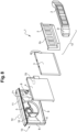
- the shield(s) 60 are formed on arms 30, here on two of the 6 arms of the support. These shields 60 are spaced from the housing 28 and the edge 35.
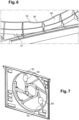
- the anti-turbulence shield 70 is placed upstream of the radiator 4, which is itself placed upstream of the fan.
- the anti-turbulence shield 71 is placed between a heat exchanger, in particular a radiator 4, and the motor-fan unit, without being formed directly on the component 13.
- the anti-turbulence shield 72 is placed downstream of a fan, in particular between the fan and the fan motor unit support.
- the shield can be an attached part, mounted for example by snap-fastening or otherwise, and placed in these different locations.
Landscapes
- Engineering & Computer Science (AREA)
- Chemical & Material Sciences (AREA)
- Combustion & Propulsion (AREA)
- Transportation (AREA)
- Mechanical Engineering (AREA)
- Structures Of Non-Positive Displacement Pumps (AREA)
- Air-Conditioning For Vehicles (AREA)
- Motor Or Generator Cooling System (AREA)
- Motor Or Generator Frames (AREA)
Description
- La présente invention a trait au domaine du refroidissement des moteurs de véhicule automobile, notamment concerne un dispositif de ventilation d'un véhicule automobile.
- Un véhicule automobile est couramment équipé de systèmes de refroidissement disposés dans son compartiment moteur. Le moteur thermique est ainsi refroidi par un apport d'air extérieur. Cet air extérieur permet de refroidir, via des échangeurs thermiques, un fluide circulant par ailleurs dans une boucle thermique du véhicule.
- Ces systèmes de refroidissement, également appelés « unités de refroidissement » comprennent le plus souvent au moins un orifice d'entrée de l'air extérieur généralement disposé sur la carrosserie du véhicule, et par exemple au niveau de la face avant du véhicule, un ou plusieurs échangeurs de chaleur agencés sur le trajet de l'air entrant ainsi qu'un groupe moto-ventilateur permettant de forcer l'arrivée d'air par exemple lorsque le véhicule est à l'arrêt.
- La position de chacun des composants de ces unités de refroidissement est prédéterminée et doit être respectée afin d'assurer le bon fonctionnement de ces unités de refroidissement. Par exemple, le groupe moto-ventilateur doit être disposé à une distance suffisamment éloignée des échangeurs de chaleur afin d'optimiser le fonctionnement de ces derniers.
- De manière connue, les composants de ces unités de refroidissement sont montés les uns après les autres sur des pièces de structure du compartiment moteur.
- Par ailleurs le bruit tonal ou le bruit harmonique généré par la circulation forcée d'air, notamment lorsque le groupe moto-ventilateur est activé, est indésirable pour les passagers du véhicule automobile. Ces bruits peuvent être entendus à l'extérieur ou à l'intérieur du véhicule.
- Ce bruit est notamment dû à des pales de ventilateur brassant de l'air trop près des bras qui portent le groupe moto-ventilateur.
- Le demandeur a constaté que, lorsqu'une pale passe à proximité des bras, le flux d'air crée des turbulences autour des bras. Ces turbulences sont la source du bruit.
- Le demandeur a constaté que le niveau du bruit dépend notamment de la vitesse du flux d'air et de la distance entre les pales et les bras. La fréquence du bruit dépend notamment du nombre de bras.
- Il serait possible de réduire le bruit selon différentes manières.
- Par exemple, il serait possible d'augmenter la distance entre les bras et les pales, mais cela augmenterait l'encombrement du dispositif, ce qui n'est acceptable pour beaucoup de constructeurs automobiles.
- Il serait également possible d'augmenter le nombre de pales pour distribuer l'énergie par pale, mais cela augmenterait les coûts et par ailleurs les performances du flux d'air peuvent êtres affectées.
- Enfin il serait possible de réduire le nombre de bras ou changer la forme des bras mais cela pourrait créer des défauts de tenue mécanique. Ceci est notamment connu des documents
CN 105 508 015 A etUS 2015/176605 A1 . - Le demandeur a constaté qu'un nouvelle approche est possible qui évite les inconvénients ci-dessus.
- L'invention a ainsi pour objet un dispositif de ventilation d'un véhicule automobile selon la revendication 1.
- L'invention permet de réduire le bruit, notamment le bruit tonal, sans avoir à modifier les autres performances du dispositif de ventilation. Comme le bruit est généré par les turbulences notamment autour du ou des bras, réduire les turbulences permet de réduire le bruit.
- Il n'est pas nécessaire d'augmenter le nombre de pales ou de réduire le nombre de bras.
- Le nombre de bras peut par exemple être inférieur ou égal à 6.
- Selon l'un des aspects de l'invention, le bouclier anti-turbulences est placé dans le passage d'air en un endroit choisi de manière à empêcher des turbulences de se former, ces turbulences seraient alors si elles n'étaient pas empêchées, parmi celles de plus grandes amplitudes dans ce passage d'air. Ces zones correspondent également à des zones de fortes vitesses de flux d'air.
- Avantageusement le ou les boucliers occupent une superficie totale inférieure à 20%, voire inférieure à 10%, voire 5%, de la superficie totale du passage d'air, afin de ne pas affecter les performances du dispositif de ventilation.
- Selon l'un des aspects de l'invention, le dispositif de ventilation comportant un support de groupe moto-ventilateur, ce support comportant au moins un bras de maintien mécanique du moteur, le bouclier est agencé pour empêcher des turbulences de se former au contact de ce bras.
- Selon l'un des aspects de l'invention, le bouclier anti-turbulences est formé sur le support de groupe moto-ventilateur.
- Selon l'un des aspects de l'invention, le bouclier anti-turbulences est rapporté, puis fixé par exemple par encliquetage ou montage à force, sur le support de groupe moto-ventilateur. Ainsi le bouclier anti-turbulences est une pièce distincte du support.
- Selon l'un des aspects de l'invention, le bouclier anti-turbulences est placé en amont d'un radiateur, qui est lui-même placé en amont du ventilateur.
- Selon l'un des aspects de l'invention, le bouclier anti-turbulences est placé entre un échangeur de chaleur, notamment un radiateur, et un ventilateur.
- Selon l'un des aspects de l'invention, le bouclier anti-turbulences est placé en aval d'un ventilateur, notamment entre le ventilateur et le support de groupe moto-ventilateur.
- Selon l'un des aspects de l'invention, le bouclier anti-turbulences est placé en aval du support de groupe moto-ventilateur.
- Selon l'un des aspects de l'invention, ces bras sont équi-angulairement répartis. En variante, les bras sont espacés avec des écarts angulaires variables.
- Selon l'un des aspects de l'invention, le support est réalisé d'un seul tenant, notamment par moulage.
- Selon l'un des aspects de l'invention, le logement comporte un anneau pour recevoir le groupe moto-ventilateur.
- Selon l'un des aspects de l'invention, les bras se raccordent à l'anneau.
- Selon l'un des aspects de l'invention, les bras sont sensiblement rectilignes ou courbes.
- Selon l'un des aspects de l'invention, certains bras seulement sont munis d'un bouclier, les autres en étant dépourvus. Ceux-là sont par exemple de largeur sensiblement constante tout le long. Ces bras sont des bras conventionnels.
- Selon l'un des aspects de l'invention, le bouclier anti-turbulences est disposé au partiellement dans cette ouverture.
- En variante, le bouclier est distant de cette bordure.
- Selon l'un des aspects de l'invention, le bouclier est adjacent à l'un des bras, et également adjacent à la bordure.
- Selon l'un des aspects de l'invention, le bouclier s'étend radialement dans l'ouverture sur une distance d'au plus la moitié de la longueur du bras, notamment au plus 114, voire 1/5 ou 1/8 de la longueur du bras.
- Selon l'un des aspects de l'invention, le bouclier comporte une face s'opposant à la circulation du flux d'air.
- Selon l'un des aspects de l'invention, cette face s'étend sensiblement dans un plan parallèle au plan de l'ouverture.
- Selon l'un des aspects de l'invention, cette face pourrait optionnellement présenter forme au moins localement bombée par rapport au plan de l'ouverture.
- Selon l'un des aspects de l'invention, le bras comprend un côté pourvu de nervures de renfort et le bouclier qui présente une forme de languette, se raccord à ce coté du bras qui est muni de nervures de renfort.
- Selon l'un des aspects de l'invention, le bouclier comporte un décrochement qui se raccorde sur un côté du bras.
- Selon l'un des aspects de l'invention, le bouclier présente une forme sensiblement choisie parmi : circulaire, polygonale, rectangulaire, carré ou toute autre forme.
- Selon l'un des aspects de l'invention, le bouclier est adjacent à une nervure annulaire, qui est notamment parallèle à l'axe transversale de l'ouverture, le long de la bordure de cette ouverture.
- Selon l'un des aspects de l'invention, il est prévu une nervure annulaire, qui est notamment parallèle à l'axe transversale de l'ouverture et s'étend le long de la bordure de cette ouverture, cette nervure présentant une hauteur surélevée, ou non, pour avoir un bon compromis entre des performance acoustiques et les performances aérauliques.
- Selon l'un des aspects de l'invention, la largeur du bouclier est notamment au moins égale à la dimension du plus gros bras.
- Selon l'un des aspects de l'invention, le bouclier est à une distance au moins égale à la distance entre le bras et les pales du ventilateur.
- Selon l'un des aspects de l'invention, cette nervure surélevée est notamment plus élevée en hauteur qu'une nervure concentrique voisine, de rayon plus grand.
- Selon l'un des aspects de l'invention, le bouclier est formé d'un seul tenant avec la région transversale et/ou l'un des bras.
- Selon l'un des aspects de l'invention, le bouclier peut avoir une forme quelconque.
- Sa largeur est notamment au moins égale à la largeur du bras plus au moins 5%.
- Sa longueur peut être comprise entre 5 % et 100 % de la longueur du bras.
- Son épaisseur est une caractéristique relativement moins importante.
- L'invention a encore pour objet un procédé pour empêcher des turbulences de se former, ce procédé comportant l'étape suivante :
- fournir un bouclier anti-turbulences de manière à empêcher des turbulences de se former dans un passage d'air d'un dispositif de ventilation d'un véhicule automobile selon la revendication 1.
- Selon l'un des aspects de l'invention, le procédé comporte l'étape suivante :
- identifier une ou plusieurs zones de fortes turbulences et de fortes vitesses d'air dans le passage d'air forcé, par exemple par simulation numérique ou par test réel,
- placer dans cette ou ces zones au moins un bouclier anti-turbulences de manière à empêcher des turbulences de se former ou à limiter ces turbulences dans cette zone ou ces zones, de manière à réduire le bruit généré par la circulation d'air.
- Selon l'un des aspects de l'invention, le dispositif de ventilation comportant un boîtier, configuré pour être traversé par un flux d'air entrant dans le véhicule, et au moins un échangeur de chaleur logé dans le boîtier. Ce boîtier comporte une pluralité de parois périphériques et au moins une paroi de fermeture disposée par exemple perpendiculairement à un bord d'extrémité verticale de ces parois périphériques pour former un logement d'encapsulage de l'au moins un échangeur de chaleur. La paroi de fermeture et une des parois périphériques forment une pièce monobloc.
- On entend par « monobloc » le fait que ces deux parois forment un unique ensemble ne pouvant être séparé sans occasionner de détérioration d'au moins une des deux parois. Autrement dit, ces deux parois assurent une continuité de matière. Ainsi les éventuelles fuites qui pourraient être liées à mauvaise liaison entre la paroi périphérique du boîtier et sa paroi de fermeture sont réduites, permettant d'obtenir un meilleur rendement de ces unités de refroidissement et par conséquent permettant de diminuer la taille des échangeurs de chaleur encapsulés dans les boîtiers de ces unités de refroidissement.
- D'autres caractéristiques, détails et avantages de la présente invention ressortiront plus clairement à la lecture de la description détaillée donnée ci-après à titre indicatif, en relation avec les différents exemples de réalisation de l'invention illustrés sur les figures suivantes :
- la
figure 1 est une vue en éclaté d'une unité de refroidissement d'un compartiment moteur, avec un dispositif de ventilation, unité dans laquelle on a rendu visible un dispositif de régulation de l'arrivée d'air extérieur dans cette unité de refroidissement, un condenseur, un radiateur et un carénage configuré pour porter un groupe moto-ventilateur, - les
figures 2 à 6 représentent différentes vues du support de groupe moto-ventilateur, - la
figure 7 est une vue d'une variante non couverte par la revendication 1. - Sur la
figure 1 sont illustrés différents éléments pouvant être compris dans une unité de refroidissement 1 destinée à être intégrée dans un compartiment moteur d'un véhicule selon la présente invention. Une telle unité de refroidissement 1 peut notamment comprendre au moins un dispositif 2 de régulation de l'arrivée d'air dans l'unité de refroidissement 1, un ou plusieurs échangeurs de chaleur empilés parmi lesquels à titre d'exemple non limitatif un condenseur 3 et un radiateur 4, et au moins un groupe moto-ventilateur 5. - Le dispositif 2 de régulation de l'arrivée d'air peut par exemple être réalisé par une calandre 2s, 2i à volets réglables tel qu'illustré à la
figure 1 . Cette calandre 2s, 2i comprend une partie supérieure 2s et une partie inférieure 2i fixées l'une sur l'autre et en décrochage l'une par rapport à l'autre. Ce décrochage peut notamment permettre de disposer un échangeur de chaleur supplémentaire. - Selon un mode de réalisation de la présente invention, l'unité de refroidissement 1 peut comprendre un premier échangeur de chaleur formé par un condenseur 3 et un deuxième échangeur de chaleur formé par un radiateur 4. Le radiateur 4 permet le refroidissement du moteur thermique via un échange entre l'air extérieur et un liquide de refroidissement circulant dans ce radiateur 4 tandis que le condenseur 3 est un élément d'un circuit de climatisation avec un réseau d'échange entre l'air frais entrant et un fluide frigorigène.
- Le groupe moto-ventilateur 5 peut quant à lui être intégré dans un carénage 6 et permet de forcer l'arrivée d'air dans l'unité de refroidissement 1 lorsque cette arrivée d'air n'est plus suffisante, par exemple dans des situations dans lesquelles le véhicule est à l'arrêt ou au moins ralenti, perturbant alors cette arrivée d'air.
- Ce carénage 6 peut présenter deux renvois latéraux 8, un bord inférieur 9 et une paroi 10 de fond dans laquelle est intégré le groupe moto-ventilateur 5.
- Selon la présente invention, les échangeurs de chaleur 3, 4, peuvent être encapsulés dans un boîtier de l'unité de refroidissement que participe à former d'une part la calandre 2s, 2i porteuse du dispositif 2 de régulation de l'arrivée d'air et d'autre part le carénage 6 intégrant le groupe moto-ventilateur 5.
- Plus particulièrement, ce boîtier présente au moins une paroi de fermeture 11 qui vient recouvrir ou fermer un volume dans lequel sont logés les échangeurs thermiques et qui est défini par l'agencement de quatre parois périphériques, à savoir : une paroi transversale avant 12, une paroi transversale arrière 13, ces parois transversales avant et arrière 12, 13 étant agencées en travers d'un flux d'air entrant dans le véhicule, et deux parois longitudinales gauche et droite non illustrées ici.
- Le flux d'air entrant dans le véhicule traverse ainsi successivement la paroi transversale avant 12 du boîtier, un ou plusieurs échangeurs de chaleur 3, 4 empilés et enfin la paroi transversale arrière 13 du boîtier.
- La paroi transversale avant 12 du boîtier correspond à la calandre 2s, 2i dans laquelle peut être intégré le dispositif 2 de régulation de l'arrivée d'air et la paroi transversale arrière 13 du boîtier porte le groupe moto-ventilateur 5.
- La paroi transversale arrière 13 du boîtier peut notamment être réalisée par la paroi 10 de fond du carénage 6, de sorte que conformément à ce qui précède, la paroi transversale arrière peut être prolongée perpendiculairement à ses bords par deux renvois latéraux 8 et un bord inférieur 9.
- Un dispositif de ventilation 20 comprend la paroi transversale arrière 13 et le groupe moto-ventilateur 5.
- Comme illustré sur les
figures 2 et 3 notamment, ce dispositif 20 comporte : - un passage d'air 21 pour de l'air mis en mouvement forcé, par aspiration par des pales non représentées du groupe moto-ventilateur 5,
- des boucliers anti-turbulences 25 et 26 agencés pour être placés dans le passage d'air 21 en des endroits, ou zones, Z choisis de manière à empêcher des turbulences de se former.
- Ces zones Z sont choisies de manière à empêcher des turbulences de se former, ces turbulences seraient alors si elles n'étaient pas empêchées, parmi celles de plus grandes amplitudes dans ce passage d'air. Ces zones correspondent également à des zones de fortes vitesses de flux d'air.
- Les boucliers 25 et 26 occupent une superficie totale inférieure à 5% de la superficie totale du passage d'air, afin de ne pas affecter les performances du dispositif de ventilation.
- La paroi transversale arrière 13 forme un support 13 de groupe moto-ventilateur. Ce support 13, ou paroi 13, comporte au moins un bras de maintien mécanique du moteur, le bouclier est agencé pour empêcher des turbulences de se former au contact de ce bras.
- Les boucliers anti-turbulences 25 et 26 sont formés sur le support 13 de groupe moto-ventilateur.
- Le support 13 comporte en outre :
- un logement 28 pour recevoir le groupe moto-ventilateur,
- une région périphérique 29,
- six bras 30 reliant le logement 28 à la région périphérique 29.
- Ces bras 30 sont équi-angulairement répartis ou non autour du logement 28.
- Le support 13 est réalisé d'un seul tenant, notamment par moulage d'une matière plastique. En variante, le support 13 peut être une pièce rapportée.
- Le logement 28 comporte un anneau 31 pour recevoir le groupe moto-ventilateur5 et les bras 30 se raccordent à l'anneau 31.
- Les bras 30 sont sensiblement rectilignes et comportent un évasement 32 à la base de jonction entre chaque bras et la région périphérique 29.
- La région périphérique 29 définit une ouverture 33 de forme sensiblement circulaire pour le passage d'air 21 et le logement pour le groupe moto-ventilateur est disposé sensiblement au centre de cette ouverture.
- Les boucliers anti-turbulences 25 et 26 sont disposés au partiellement dans cette ouverture 33 et donc dans le passage d'air 21.
- Cette ouverture 33 présente une bordure circulaire 35, et les boucliers 25 et 26 sont adjacents à cette bordure 35.
- Les boucliers 25 et 26 sont disposés entre deux bras consécutifs 30 et sont adjacents à l'un des bras 30, et également adjacent à la bordure 35.
- Les boucliers 25 et 26 s'étendent radialement dans l'ouverture sur une distance d'au plus la moitié de la longueur du bras, notamment au plus 1/5 ou 1/8 de la longueur du bras 30, longueur mesurée depuis l'anneau 31 jusqu'à la bordure 35.
- Comme illustré sur la
figure 3 , les boucliers 25 et 25 comportent chacun une face 40 et 41 respectivement s'opposant à la circulation du flux d'air. - La face 40 du bouclier 40 s'étend sensiblement dans un plan P parallèle au plan de l'ouverture 33, comme illustré sur la
figure 4 . - L'autre face 41 du bouclier 26 présente une forme bombée par rapport au plan P de l'ouverture 33, comme visible sur la
figure 5 . Cette forme bombée présente une concavité tournée parallèlement au flux d'air. - Cette face 41 pourrait être plane et non bombée.
- Le bouclier 25 présente une forme de languette, comme visible sur la
figure 4 , avec une extrémité relevée 44. - Chaque bras 30 comprend un côté 45 pourvu de nervures de renfort 46, comme visible sur la
figure 2 , et le bouclier 26 qui présente une forme de languette, se raccord à ce coté 45 du bras qui est muni de nervures de renfort 46. - Cette languette du bouclier 25 s'étend sensiblement le long de la bordure 35 de l'ouverture 33.
- Le bouclier 25 comporte un décrochement 47 qui se raccorde sur un côté 45 du bras 30.
- Le bouclier 25, selon les besoins, peut présenter une forme sensiblement choisie parmi : circulaire, polygonale, rectangulaire, carré ou toute autre forme.
- Les boucliers 25 et 26 sont adjacents à une nervure annulaire 48, qui est notamment parallèle à l'axe transversale de l'ouverture, le long de la bordure de cette ouverture 33.
- Comme illustré sur la
figure 6 , un élément 50 supplémentaire est formé sur la nervure annulaire 48, qui est parallèle à l'axe transversale de l'ouverture et s'étend le long de la bordure 35 de cette ouverture, cette nervure 48 présentant une hauteur surélevée, ou non, pour avoir un bon compromis entre des performance acoustiques et les performances aérauliques. - Cette nervure surélevée 48 est plus élevée en hauteur qu'une nervure concentrique voisine 51, de rayon plus grand. Cette nervure 48 présente des encoches 55.
- Les nervures 48 et 51 peuvent en variante avoir la même hauteur.
- Dans l'exemple illustré en
figure 7 et non couvert par la revendication 1, le ou les boucliers 60 sont formés sur des bras 30, ici sur deux des 6 bras du support. Ces boucliers 60 sont espacés du logement 28 et de la bordure 35. - Comme on peut le voir sur la
figure 8 , selon un autre aspect de l'invention non couvert par la revendication 1, le bouclier anti-turbulences 70 est placé en amont du radiateur 4, qui est lui-même placé en amont du ventilateur. - En variante non couverte par la revendication 1, le bouclier anti-turbulences 71 est placé entre un échangeur de chaleur, notamment un radiateur 4, et le groupe moto-ventilateur, sans être formé directement sur le composant 13.
- En variante encore et non couverte par la revendication 1, le bouclier anti-turbulences 72 est placé en aval d'un ventilateur, notamment entre le ventilateur et le support de groupe moto-ventilateur.
- Dans ces cas non couverts par la revendication 1, le bouclier peut être une pièce rapportée, montée par exemple par encliquetage ou autre, et disposé dans ces différents emplacements.
Claims (7)
- Dispositif de ventilation (20) d'un véhicule automobile, ce dispositif (20) comportant :- un passage d'air (21) pour de l'air mis en mouvement forcé, notamment par aspiration,- au moins un bouclier anti-turbulences (25 ; 26 ; 60 ; 70 ; 71 ; 72) agencé pour être placé dans le passage d'air (21) en un endroit choisi de manière à empêcher des turbulences de se former,- un support (13) de groupe moto-ventilateur (5), ce support (13) comportant :la région périphérique (29) définit une ouverture (33) de forme sensiblement circulaire et le logement (28) pour le groupe moto-ventilateur (5) est disposé sensiblement au centre de cette ouverture (33), et cette ouverture (33) présente une bordure (35), notamment circulaire, le bouclier (25 ; 26 ; 60 ; 70 ; 71 ; 72) est adjacent à cette bordure (35) et dans lequel le bouclier (25 ; 26 ; 60 ; 70 ; 71 ; 72) est disposé entre deux bras (30) consécutifs et caractérisé en ce que le bouclier (25 ; 26 ; 60 ; 70 ; 71 ; 72) présente une forme de languette et la languette du bouclier (25 ; 26 ; 60 ; 70 ; 71 ; 72) s'étend sensiblement le long de la bordure (35) de l'ouverture (33).o au moins un bras (30) de maintien mécanique du moteur, le bouclier (25 ; 26 ; 60 ; 70 ; 71 ; 72) étant agencé pour empêcher des turbulences de se former au contact de ce bras (30),o un logement (28) pour recevoir le groupe moto-ventilateur (5),o une région périphérique (29),o au moins un bras (30) reliant le logement (28) à la région périphérique (29), notamment une pluralité de bras (30) reliant le logement (28) à la région périphérique (29),
- Dispositif (20) selon la revendication précédente, dans lequel le bouclier anti-turbulences (25 ; 26 ; 60 ; 70 ; 71 ; 72) est formé sur le support (13) de groupe moto-ventilateur (5).
- Dispositif (20) selon l'une des revendications précédentes, dans lequel le bouclier anti-turbulences (25 ; 26 ; 60 ; 70 ; 71 ; 72) est placé en amont d'un radiateur (4), qui est lui-même placé en amont du ventilateur.
- Dispositif (20) selon la revendication 1, dans lequel certains bras (30) seulement sont munis d'un bouclier (25 ; 26 ; 60 ; 70 ; 71 ; 72), les autres en étant dépourvus.
- Dispositif (20) selon l'une des revendications précédentes, dans lequel le bouclier (25 ; 26 ; 60 ; 70 ; 71 ; 72) est à une distance au moins égale à la distance entre le bras (30) et les pales du ventilateur.
- Procédé pour empêcher des turbulences de se former, ce procédé comportant l'étape suivante :- fournir un bouclier anti-turbulences (25 ; 26 ; 60 ; 70 ; 71 ; 72) de manière à empêcher des turbulences de se former dans un passage d'air (21) d'un dispositif de ventilation (20) d'un véhicule automobile selon l'une des revendications 1 à 5.
- Procédé selon la revendication précédente, comportant l'étape suivante :- identifier une ou plusieurs zones de fortes turbulences et de fortes vitesses d'air dans le passage d'air forcé (21), par exemple par simulation numérique ou par test réel,- placer dans cette ou ces zones (Z) au moins un bouclier anti-turbulences (25 ; 26 ; 60 ; 70 ; 71 ; 72) de manière à empêcher des turbulences de se former ou à limiter ces turbulences dans cette zone ou ces zones (Z), de manière à réduire le bruit généré par la circulation d'air.
Applications Claiming Priority (2)
| Application Number | Priority Date | Filing Date | Title |
|---|---|---|---|
| FR1854253A FR3081383B1 (fr) | 2018-05-22 | 2018-05-22 | Dispositif de ventilation d’un vehicule automobile |
| PCT/FR2019/051129 WO2019224460A2 (fr) | 2018-05-22 | 2019-05-17 | Dispositif de ventilation d'un véhicule automobile |
Publications (2)
| Publication Number | Publication Date |
|---|---|
| EP3768540A2 EP3768540A2 (fr) | 2021-01-27 |
| EP3768540B1 true EP3768540B1 (fr) | 2024-06-26 |
Family
ID=65685409
Family Applications (1)
| Application Number | Title | Priority Date | Filing Date |
|---|---|---|---|
| EP19790041.8A Active EP3768540B1 (fr) | 2018-05-22 | 2019-05-17 | Dispositif de ventilation d'un véhicule automobile |
Country Status (5)
| Country | Link |
|---|---|
| US (1) | US11679664B2 (fr) |
| EP (1) | EP3768540B1 (fr) |
| CN (1) | CN112154076B (fr) |
| FR (1) | FR3081383B1 (fr) |
| WO (1) | WO2019224460A2 (fr) |
Families Citing this family (1)
| Publication number | Priority date | Publication date | Assignee | Title |
|---|---|---|---|---|
| KR102794190B1 (ko) * | 2021-02-05 | 2025-04-15 | 한온시스템 주식회사 | 팬 쉬라우드 조립체 |
Family Cites Families (33)
| Publication number | Priority date | Publication date | Assignee | Title |
|---|---|---|---|---|
| FR2373697A1 (fr) * | 1976-12-13 | 1978-07-07 | Ferodo Sa | Groupe moto-ventilateur a moteur refroidi |
| US4685513A (en) * | 1981-11-24 | 1987-08-11 | General Motors Corporation | Engine cooling fan and fan shrouding arrangement |
| US5156568A (en) * | 1990-03-29 | 1992-10-20 | Ricci Russell L | Car ventilator |
| US5730583A (en) * | 1994-09-29 | 1998-03-24 | Valeo Thermique Moteur | Axial flow fan blade structure |
| US6139265A (en) * | 1996-05-01 | 2000-10-31 | Valeo Thermique Moteur | Stator fan |
| JPH10205497A (ja) * | 1996-11-21 | 1998-08-04 | Zexel Corp | 冷却空気導入排出装置 |
| US6206635B1 (en) * | 1998-12-07 | 2001-03-27 | Valeo, Inc. | Fan stator |
| FR2788116B1 (fr) * | 1998-12-30 | 2001-05-18 | Valeo Climatisation | Dispositif de chauffage, ventilation et/ou climatisation comportant une boucle thermique equipee d'un evaporateur |
| FR2788123B1 (fr) * | 1998-12-30 | 2001-05-18 | Valeo Climatisation | Evaporateur, appareil de chauffage et/ou de climatisation et vehicule comportant un tel evaporateur |
| US6142733A (en) * | 1998-12-30 | 2000-11-07 | Valeo Thermique Moteur | Stator for fan |
| FR2788117B1 (fr) * | 1998-12-30 | 2001-03-02 | Valeo Climatisation | Dispositif de chauffage, ventilation et/ou climatisation comportant une boucle thermique equipee d'un evaporateur |
| EP1337758B1 (fr) * | 2000-11-08 | 2006-02-08 | Robert Bosch Corporation | Ventilateur axial a rendement eleve et adapte a l'entree d'air |
| US7374408B2 (en) * | 2003-12-22 | 2008-05-20 | Valeo Electrical Systems, Inc. | Engine cooling fan motor with reduced water entry protection |
| US7481287B2 (en) * | 2004-04-02 | 2009-01-27 | Deere & Company | Vehicle cooling package |
| US7811055B2 (en) * | 2004-04-26 | 2010-10-12 | Behr Gmbh & Co. Kg | Fan housing for a heat exchanger, particular for motor vehicles |
| KR101284889B1 (ko) * | 2007-03-27 | 2013-07-10 | 한라비스테온공조 주식회사 | 팬 및 쉬라우드의 조립체 |
| JP4367526B2 (ja) * | 2007-05-23 | 2009-11-18 | 株式会社デンソー | クーリングモジュール |
| JP4665957B2 (ja) * | 2007-11-26 | 2011-04-06 | 株式会社デンソー | エアエレメント収納ケースおよびこれを備えたファンシュラウド部材 |
| FR2926411B1 (fr) * | 2008-01-15 | 2015-05-22 | Valeo Systemes Thermiques | Dispositif de support de moteur pour systeme de ventilation, chauffage et/ou climatisation. |
| US8510893B2 (en) * | 2008-06-20 | 2013-08-20 | Colgate-Palmolive Company | Toothbrush with visual and/or other sensory effects |
| FR2940197B1 (fr) * | 2008-12-18 | 2011-03-25 | Renault Sas | Procede et systeme de refroidissement d'un moteur de vehicule |
| US8807113B2 (en) * | 2009-05-04 | 2014-08-19 | Ford Global Technologies, Llc | Device and method for integrating an air cleaner into a radiator fan shroud |
| FR2950574B1 (fr) * | 2009-09-29 | 2012-03-23 | Valeo Systemes Thermiques | Bloc d'echange thermique pour vehicule automobile |
| DK200901119A (da) * | 2009-10-13 | 2011-04-14 | Novenco As | System til opbygning af en aksialblæser |
| US20130196588A1 (en) * | 2012-01-26 | 2013-08-01 | Chang LIAO | Ceiling fan |
| FR3000186B1 (fr) * | 2012-12-21 | 2018-11-30 | Valeo Systemes Thermiques | Echangeur de chaleur entre un liquide caloporteur et un fluide refrigerant, notamment pour vehicule automobile |
| DE102013112825A1 (de) * | 2013-11-20 | 2015-05-21 | Valeo Klimasysteme Gmbh | Frontmodul eines Fahrzeugs |
| CA2875347C (fr) * | 2013-12-19 | 2022-04-19 | Airius Ip Holdings, Llc | Dispositifs, systemes et procedes de deplacement d'air en colonne |
| FR3015379B1 (fr) * | 2013-12-20 | 2017-06-09 | Valeo Systemes Thermiques | Ventilateur pour automobile comportant un stator en amont de l'helice |
| US10267209B2 (en) * | 2015-01-21 | 2019-04-23 | Hanon Systems | Fan shroud for motor vehicle |
| CN105508015B (zh) * | 2016-01-22 | 2020-04-24 | 上海博泽电机有限公司 | 一种低旋转噪声的汽车发动机冷却风扇 |
| US10487852B2 (en) * | 2016-06-24 | 2019-11-26 | Airius Ip Holdings, Llc | Air moving device |
| DE102016221642A1 (de) * | 2016-11-04 | 2018-05-09 | Brose Fahrzeugteile GmbH & Co. Kommanditgesellschaft, Würzburg | Zargenvorrichtung für ein Kühlerlüftermodul, ein Kühlerlüftermodul mit einer Zargenvorrichtung und Fahrzeug mit einem solchen Kühlerlüftermodul |
-
2018
- 2018-05-22 FR FR1854253A patent/FR3081383B1/fr active Active
-
2019
- 2019-05-17 WO PCT/FR2019/051129 patent/WO2019224460A2/fr not_active Ceased
- 2019-05-17 US US17/056,879 patent/US11679664B2/en active Active
- 2019-05-17 EP EP19790041.8A patent/EP3768540B1/fr active Active
- 2019-05-17 CN CN201980033816.5A patent/CN112154076B/zh active Active
Also Published As
| Publication number | Publication date |
|---|---|
| EP3768540A2 (fr) | 2021-01-27 |
| US11679664B2 (en) | 2023-06-20 |
| US20210197659A1 (en) | 2021-07-01 |
| WO2019224460A2 (fr) | 2019-11-28 |
| CN112154076A (zh) | 2020-12-29 |
| CN112154076B (zh) | 2024-03-15 |
| FR3081383A1 (fr) | 2019-11-29 |
| FR3081383B1 (fr) | 2023-10-20 |
| WO2019224460A3 (fr) | 2020-03-12 |
Similar Documents
| Publication | Publication Date | Title |
|---|---|---|
| WO2020188188A1 (fr) | Module de refroidissement pour vehicule automobile electrique a turbomachine tangentielle | |
| WO2020058608A1 (fr) | Dispositif de ventilation pour vehicule automobile | |
| WO2020188191A1 (fr) | Module de refroidissement pour véhicule automobile électrique à turbomachine tangentielle | |
| WO2022200168A1 (fr) | Module de refroidissement pour vehicule automobile electrique ou hybride | |
| FR2904950A1 (fr) | Cloison anti-recyclage evolutive | |
| WO2019224460A2 (fr) | Dispositif de ventilation d'un véhicule automobile | |
| FR3079557A1 (fr) | Dispositif de ventilation pour vehicule automobile | |
| EP4204669B1 (fr) | Module de refroidissement pour véhicule automobile électrique à turbomachine tangentielle | |
| WO2020188190A1 (fr) | Module de refroidissement a zone sacrificielle pour vehicule automobile electrique | |
| FR3121176A1 (fr) | Module de refroidissement pour véhicule automobile électrique ou hybride | |
| WO2020188187A1 (fr) | Module de refroidissement pour vehicule automobile electrique a turbomachine tangentielle | |
| EP3938632B1 (fr) | Module de refroidissement pour véhicule automobile électrique à turbomachine tangentielle | |
| EP3976408B1 (fr) | Module de refroidissement pour véhicule automobile électrique à turbomachine tangentielle | |
| FR3068389A1 (fr) | Unite de refroidissement pour compartiment moteur | |
| WO2022096203A1 (fr) | Module de refroidissement pour vehicule automobile electrique ou hybride a turbomachine tangentielle | |
| FR3067294B1 (fr) | Calandre pour vehicule automobile | |
| WO2017187047A1 (fr) | Collecteur et dispositif de refroidissement associe | |
| FR3121075A1 (fr) | Module de refroidissement pour véhicule automobile électrique ou hybride à turbomachine tangentielle | |
| FR3125468A1 (fr) | Volet extrudé pour dispositif d’obturation d’entrée d’air de face avant de véhicule automobile | |
| FR3093762A1 (fr) | Module de refroidissement pour véhicule automobile électrique à turbomachine tangentielle | |
| FR3085885A1 (fr) | Dispositif de ventilation pour vehicule automobile | |
| FR3111183A1 (fr) | Persienne d’aération pour véhicule et véhicule associé | |
| FR3093764A1 (fr) | Module de refroidissement pour véhicule automobile électrique à turbomachine tangentielle | |
| EP1728987A1 (fr) | Dispositif de refroidissement pour véhicule automobile, groupe moto-ventilateur pour un tel dispositif, et véhicule automobile correspondant |
Legal Events
| Date | Code | Title | Description |
|---|---|---|---|
| STAA | Information on the status of an ep patent application or granted ep patent |
Free format text: STATUS: UNKNOWN |
|
| STAA | Information on the status of an ep patent application or granted ep patent |
Free format text: STATUS: THE INTERNATIONAL PUBLICATION HAS BEEN MADE |
|
| PUAI | Public reference made under article 153(3) epc to a published international application that has entered the european phase |
Free format text: ORIGINAL CODE: 0009012 |
|
| STAA | Information on the status of an ep patent application or granted ep patent |
Free format text: STATUS: REQUEST FOR EXAMINATION WAS MADE |
|
| 17P | Request for examination filed |
Effective date: 20201020 |
|
| AK | Designated contracting states |
Kind code of ref document: A2 Designated state(s): AL AT BE BG CH CY CZ DE DK EE ES FI FR GB GR HR HU IE IS IT LI LT LU LV MC MK MT NL NO PL PT RO RS SE SI SK SM TR |
|
| AX | Request for extension of the european patent |
Extension state: BA ME |
|
| DAV | Request for validation of the european patent (deleted) | ||
| DAX | Request for extension of the european patent (deleted) | ||
| STAA | Information on the status of an ep patent application or granted ep patent |
Free format text: STATUS: EXAMINATION IS IN PROGRESS |
|
| 17Q | First examination report despatched |
Effective date: 20220209 |
|
| P01 | Opt-out of the competence of the unified patent court (upc) registered |
Effective date: 20230528 |
|
| GRAP | Despatch of communication of intention to grant a patent |
Free format text: ORIGINAL CODE: EPIDOSNIGR1 |
|
| STAA | Information on the status of an ep patent application or granted ep patent |
Free format text: STATUS: GRANT OF PATENT IS INTENDED |
|
| INTG | Intention to grant announced |
Effective date: 20240125 |
|
| GRAS | Grant fee paid |
Free format text: ORIGINAL CODE: EPIDOSNIGR3 |
|
| GRAA | (expected) grant |
Free format text: ORIGINAL CODE: 0009210 |
|
| STAA | Information on the status of an ep patent application or granted ep patent |
Free format text: STATUS: THE PATENT HAS BEEN GRANTED |
|
| AK | Designated contracting states |
Kind code of ref document: B1 Designated state(s): AL AT BE BG CH CY CZ DE DK EE ES FI FR GB GR HR HU IE IS IT LI LT LU LV MC MK MT NL NO PL PT RO RS SE SI SK SM TR |
|
| REG | Reference to a national code |
Ref country code: GB Ref legal event code: FG4D Free format text: NOT ENGLISH |
|
| REG | Reference to a national code |
Ref country code: CH Ref legal event code: EP |
|
| REG | Reference to a national code |
Ref country code: DE Ref legal event code: R096 Ref document number: 602019054270 Country of ref document: DE |
|
| PG25 | Lapsed in a contracting state [announced via postgrant information from national office to epo] |
Ref country code: BG Free format text: LAPSE BECAUSE OF FAILURE TO SUBMIT A TRANSLATION OF THE DESCRIPTION OR TO PAY THE FEE WITHIN THE PRESCRIBED TIME-LIMIT Effective date: 20240626 |
|
| PG25 | Lapsed in a contracting state [announced via postgrant information from national office to epo] |
Ref country code: FI Free format text: LAPSE BECAUSE OF FAILURE TO SUBMIT A TRANSLATION OF THE DESCRIPTION OR TO PAY THE FEE WITHIN THE PRESCRIBED TIME-LIMIT Effective date: 20240626 Ref country code: HR Free format text: LAPSE BECAUSE OF FAILURE TO SUBMIT A TRANSLATION OF THE DESCRIPTION OR TO PAY THE FEE WITHIN THE PRESCRIBED TIME-LIMIT Effective date: 20240626 |
|
| REG | Reference to a national code |
Ref country code: LT Ref legal event code: MG9D |
|
| PG25 | Lapsed in a contracting state [announced via postgrant information from national office to epo] |
Ref country code: GR Free format text: LAPSE BECAUSE OF FAILURE TO SUBMIT A TRANSLATION OF THE DESCRIPTION OR TO PAY THE FEE WITHIN THE PRESCRIBED TIME-LIMIT Effective date: 20240927 |
|
| PG25 | Lapsed in a contracting state [announced via postgrant information from national office to epo] |
Ref country code: LV Free format text: LAPSE BECAUSE OF FAILURE TO SUBMIT A TRANSLATION OF THE DESCRIPTION OR TO PAY THE FEE WITHIN THE PRESCRIBED TIME-LIMIT Effective date: 20240626 |
|
| REG | Reference to a national code |
Ref country code: NL Ref legal event code: MP Effective date: 20240626 |
|
| PG25 | Lapsed in a contracting state [announced via postgrant information from national office to epo] |
Ref country code: NO Free format text: LAPSE BECAUSE OF FAILURE TO SUBMIT A TRANSLATION OF THE DESCRIPTION OR TO PAY THE FEE WITHIN THE PRESCRIBED TIME-LIMIT Effective date: 20240926 Ref country code: LV Free format text: LAPSE BECAUSE OF FAILURE TO SUBMIT A TRANSLATION OF THE DESCRIPTION OR TO PAY THE FEE WITHIN THE PRESCRIBED TIME-LIMIT Effective date: 20240626 Ref country code: HR Free format text: LAPSE BECAUSE OF FAILURE TO SUBMIT A TRANSLATION OF THE DESCRIPTION OR TO PAY THE FEE WITHIN THE PRESCRIBED TIME-LIMIT Effective date: 20240626 Ref country code: GR Free format text: LAPSE BECAUSE OF FAILURE TO SUBMIT A TRANSLATION OF THE DESCRIPTION OR TO PAY THE FEE WITHIN THE PRESCRIBED TIME-LIMIT Effective date: 20240927 Ref country code: FI Free format text: LAPSE BECAUSE OF FAILURE TO SUBMIT A TRANSLATION OF THE DESCRIPTION OR TO PAY THE FEE WITHIN THE PRESCRIBED TIME-LIMIT Effective date: 20240626 Ref country code: BG Free format text: LAPSE BECAUSE OF FAILURE TO SUBMIT A TRANSLATION OF THE DESCRIPTION OR TO PAY THE FEE WITHIN THE PRESCRIBED TIME-LIMIT Effective date: 20240626 Ref country code: RS Free format text: LAPSE BECAUSE OF FAILURE TO SUBMIT A TRANSLATION OF THE DESCRIPTION OR TO PAY THE FEE WITHIN THE PRESCRIBED TIME-LIMIT Effective date: 20240926 |
|
| PG25 | Lapsed in a contracting state [announced via postgrant information from national office to epo] |
Ref country code: NL Free format text: LAPSE BECAUSE OF FAILURE TO SUBMIT A TRANSLATION OF THE DESCRIPTION OR TO PAY THE FEE WITHIN THE PRESCRIBED TIME-LIMIT Effective date: 20240626 |
|
| REG | Reference to a national code |
Ref country code: AT Ref legal event code: MK05 Ref document number: 1697436 Country of ref document: AT Kind code of ref document: T Effective date: 20240626 |
|
| PG25 | Lapsed in a contracting state [announced via postgrant information from national office to epo] |
Ref country code: NL Free format text: LAPSE BECAUSE OF FAILURE TO SUBMIT A TRANSLATION OF THE DESCRIPTION OR TO PAY THE FEE WITHIN THE PRESCRIBED TIME-LIMIT Effective date: 20240626 |
|
| PG25 | Lapsed in a contracting state [announced via postgrant information from national office to epo] |
Ref country code: PT Free format text: LAPSE BECAUSE OF FAILURE TO SUBMIT A TRANSLATION OF THE DESCRIPTION OR TO PAY THE FEE WITHIN THE PRESCRIBED TIME-LIMIT Effective date: 20241028 |
|
| PG25 | Lapsed in a contracting state [announced via postgrant information from national office to epo] |
Ref country code: PT Free format text: LAPSE BECAUSE OF FAILURE TO SUBMIT A TRANSLATION OF THE DESCRIPTION OR TO PAY THE FEE WITHIN THE PRESCRIBED TIME-LIMIT Effective date: 20241028 |
|
| PG25 | Lapsed in a contracting state [announced via postgrant information from national office to epo] |
Ref country code: PL Free format text: LAPSE BECAUSE OF FAILURE TO SUBMIT A TRANSLATION OF THE DESCRIPTION OR TO PAY THE FEE WITHIN THE PRESCRIBED TIME-LIMIT Effective date: 20240626 |
|
| PG25 | Lapsed in a contracting state [announced via postgrant information from national office to epo] |
Ref country code: EE Free format text: LAPSE BECAUSE OF FAILURE TO SUBMIT A TRANSLATION OF THE DESCRIPTION OR TO PAY THE FEE WITHIN THE PRESCRIBED TIME-LIMIT Effective date: 20240626 |
|
| PG25 | Lapsed in a contracting state [announced via postgrant information from national office to epo] |
Ref country code: AT Free format text: LAPSE BECAUSE OF FAILURE TO SUBMIT A TRANSLATION OF THE DESCRIPTION OR TO PAY THE FEE WITHIN THE PRESCRIBED TIME-LIMIT Effective date: 20240626 Ref country code: IS Free format text: LAPSE BECAUSE OF FAILURE TO SUBMIT A TRANSLATION OF THE DESCRIPTION OR TO PAY THE FEE WITHIN THE PRESCRIBED TIME-LIMIT Effective date: 20241026 |
|
| PG25 | Lapsed in a contracting state [announced via postgrant information from national office to epo] |
Ref country code: CZ Free format text: LAPSE BECAUSE OF FAILURE TO SUBMIT A TRANSLATION OF THE DESCRIPTION OR TO PAY THE FEE WITHIN THE PRESCRIBED TIME-LIMIT Effective date: 20240626 |
|
| PG25 | Lapsed in a contracting state [announced via postgrant information from national office to epo] |
Ref country code: RO Free format text: LAPSE BECAUSE OF FAILURE TO SUBMIT A TRANSLATION OF THE DESCRIPTION OR TO PAY THE FEE WITHIN THE PRESCRIBED TIME-LIMIT Effective date: 20240626 Ref country code: SK Free format text: LAPSE BECAUSE OF FAILURE TO SUBMIT A TRANSLATION OF THE DESCRIPTION OR TO PAY THE FEE WITHIN THE PRESCRIBED TIME-LIMIT Effective date: 20240626 |
|
| PG25 | Lapsed in a contracting state [announced via postgrant information from national office to epo] |
Ref country code: ES Free format text: LAPSE BECAUSE OF FAILURE TO SUBMIT A TRANSLATION OF THE DESCRIPTION OR TO PAY THE FEE WITHIN THE PRESCRIBED TIME-LIMIT Effective date: 20240626 Ref country code: SM Free format text: LAPSE BECAUSE OF FAILURE TO SUBMIT A TRANSLATION OF THE DESCRIPTION OR TO PAY THE FEE WITHIN THE PRESCRIBED TIME-LIMIT Effective date: 20240626 |
|
| PG25 | Lapsed in a contracting state [announced via postgrant information from national office to epo] |
Ref country code: SM Free format text: LAPSE BECAUSE OF FAILURE TO SUBMIT A TRANSLATION OF THE DESCRIPTION OR TO PAY THE FEE WITHIN THE PRESCRIBED TIME-LIMIT Effective date: 20240626 Ref country code: SK Free format text: LAPSE BECAUSE OF FAILURE TO SUBMIT A TRANSLATION OF THE DESCRIPTION OR TO PAY THE FEE WITHIN THE PRESCRIBED TIME-LIMIT Effective date: 20240626 Ref country code: RO Free format text: LAPSE BECAUSE OF FAILURE TO SUBMIT A TRANSLATION OF THE DESCRIPTION OR TO PAY THE FEE WITHIN THE PRESCRIBED TIME-LIMIT Effective date: 20240626 Ref country code: PL Free format text: LAPSE BECAUSE OF FAILURE TO SUBMIT A TRANSLATION OF THE DESCRIPTION OR TO PAY THE FEE WITHIN THE PRESCRIBED TIME-LIMIT Effective date: 20240626 Ref country code: IS Free format text: LAPSE BECAUSE OF FAILURE TO SUBMIT A TRANSLATION OF THE DESCRIPTION OR TO PAY THE FEE WITHIN THE PRESCRIBED TIME-LIMIT Effective date: 20241026 Ref country code: ES Free format text: LAPSE BECAUSE OF FAILURE TO SUBMIT A TRANSLATION OF THE DESCRIPTION OR TO PAY THE FEE WITHIN THE PRESCRIBED TIME-LIMIT Effective date: 20240626 Ref country code: EE Free format text: LAPSE BECAUSE OF FAILURE TO SUBMIT A TRANSLATION OF THE DESCRIPTION OR TO PAY THE FEE WITHIN THE PRESCRIBED TIME-LIMIT Effective date: 20240626 Ref country code: CZ Free format text: LAPSE BECAUSE OF FAILURE TO SUBMIT A TRANSLATION OF THE DESCRIPTION OR TO PAY THE FEE WITHIN THE PRESCRIBED TIME-LIMIT Effective date: 20240626 Ref country code: AT Free format text: LAPSE BECAUSE OF FAILURE TO SUBMIT A TRANSLATION OF THE DESCRIPTION OR TO PAY THE FEE WITHIN THE PRESCRIBED TIME-LIMIT Effective date: 20240626 |
|
| PG25 | Lapsed in a contracting state [announced via postgrant information from national office to epo] |
Ref country code: IT Free format text: LAPSE BECAUSE OF FAILURE TO SUBMIT A TRANSLATION OF THE DESCRIPTION OR TO PAY THE FEE WITHIN THE PRESCRIBED TIME-LIMIT Effective date: 20240626 |
|
| REG | Reference to a national code |
Ref country code: DE Ref legal event code: R097 Ref document number: 602019054270 Country of ref document: DE |
|
| PG25 | Lapsed in a contracting state [announced via postgrant information from national office to epo] |
Ref country code: DK Free format text: LAPSE BECAUSE OF FAILURE TO SUBMIT A TRANSLATION OF THE DESCRIPTION OR TO PAY THE FEE WITHIN THE PRESCRIBED TIME-LIMIT Effective date: 20240626 |
|
| PLBE | No opposition filed within time limit |
Free format text: ORIGINAL CODE: 0009261 |
|
| STAA | Information on the status of an ep patent application or granted ep patent |
Free format text: STATUS: NO OPPOSITION FILED WITHIN TIME LIMIT |
|
| 26N | No opposition filed |
Effective date: 20250327 |
|
| PGFP | Annual fee paid to national office [announced via postgrant information from national office to epo] |
Ref country code: DE Payment date: 20250513 Year of fee payment: 7 |
|
| PGFP | Annual fee paid to national office [announced via postgrant information from national office to epo] |
Ref country code: FR Payment date: 20250530 Year of fee payment: 7 |
|
| PG25 | Lapsed in a contracting state [announced via postgrant information from national office to epo] |
Ref country code: SE Free format text: LAPSE BECAUSE OF FAILURE TO SUBMIT A TRANSLATION OF THE DESCRIPTION OR TO PAY THE FEE WITHIN THE PRESCRIBED TIME-LIMIT Effective date: 20240626 |
|
| REG | Reference to a national code |
Ref country code: CH Ref legal event code: H13 Free format text: ST27 STATUS EVENT CODE: U-0-0-H10-H13 (AS PROVIDED BY THE NATIONAL OFFICE) Effective date: 20251223 |
|
| PG25 | Lapsed in a contracting state [announced via postgrant information from national office to epo] |
Ref country code: LU Free format text: LAPSE BECAUSE OF NON-PAYMENT OF DUE FEES Effective date: 20250517 |
|
| PG25 | Lapsed in a contracting state [announced via postgrant information from national office to epo] |
Ref country code: CH Free format text: LAPSE BECAUSE OF NON-PAYMENT OF DUE FEES Effective date: 20250531 |
|
| GBPC | Gb: european patent ceased through non-payment of renewal fee |
Effective date: 20250517 |
|
| REG | Reference to a national code |
Ref country code: BE Ref legal event code: MM Effective date: 20250531 |
|
| PG25 | Lapsed in a contracting state [announced via postgrant information from national office to epo] |
Ref country code: MC Free format text: LAPSE BECAUSE OF FAILURE TO SUBMIT A TRANSLATION OF THE DESCRIPTION OR TO PAY THE FEE WITHIN THE PRESCRIBED TIME-LIMIT Effective date: 20240626 |
|
| PG25 | Lapsed in a contracting state [announced via postgrant information from national office to epo] |
Ref country code: GB Free format text: LAPSE BECAUSE OF NON-PAYMENT OF DUE FEES Effective date: 20250517 |
|
| PG25 | Lapsed in a contracting state [announced via postgrant information from national office to epo] |
Ref country code: IE Free format text: LAPSE BECAUSE OF NON-PAYMENT OF DUE FEES Effective date: 20250517 |
|
| PG25 | Lapsed in a contracting state [announced via postgrant information from national office to epo] |
Ref country code: BE Free format text: LAPSE BECAUSE OF NON-PAYMENT OF DUE FEES Effective date: 20250531 |