EP3768529B1 - Mit einem hochfrequenzkommunikationsmodul ausgestattete schwerlastfahrzeugluftreifen - Google Patents
Mit einem hochfrequenzkommunikationsmodul ausgestattete schwerlastfahrzeugluftreifen Download PDFInfo
- Publication number
- EP3768529B1 EP3768529B1 EP19720938.0A EP19720938A EP3768529B1 EP 3768529 B1 EP3768529 B1 EP 3768529B1 EP 19720938 A EP19720938 A EP 19720938A EP 3768529 B1 EP3768529 B1 EP 3768529B1
- Authority
- EP
- European Patent Office
- Prior art keywords
- carcass reinforcement
- layer
- reinforcement layer
- turn
- radially
- Prior art date
- Legal status (The legal status is an assumption and is not a legal conclusion. Google has not performed a legal analysis and makes no representation as to the accuracy of the status listed.)
- Active
Links
Images
Classifications
-
- B—PERFORMING OPERATIONS; TRANSPORTING
- B60—VEHICLES IN GENERAL
- B60C—VEHICLE TYRES; TYRE INFLATION; TYRE CHANGING; CONNECTING VALVES TO INFLATABLE ELASTIC BODIES IN GENERAL; DEVICES OR ARRANGEMENTS RELATED TO TYRES
- B60C9/00—Reinforcements or ply arrangement of pneumatic tyres
- B60C9/02—Carcasses
-
- B—PERFORMING OPERATIONS; TRANSPORTING
- B60—VEHICLES IN GENERAL
- B60C—VEHICLE TYRES; TYRE INFLATION; TYRE CHANGING; CONNECTING VALVES TO INFLATABLE ELASTIC BODIES IN GENERAL; DEVICES OR ARRANGEMENTS RELATED TO TYRES
- B60C15/00—Tyre beads, e.g. ply turn-up or overlap
- B60C15/0009—Tyre beads, e.g. ply turn-up or overlap features of the carcass terminal portion
- B60C15/0054—Tyre beads, e.g. ply turn-up or overlap features of the carcass terminal portion with ply turn-up portion parallel and adjacent to carcass main portion
-
- B—PERFORMING OPERATIONS; TRANSPORTING
- B60—VEHICLES IN GENERAL
- B60C—VEHICLE TYRES; TYRE INFLATION; TYRE CHANGING; CONNECTING VALVES TO INFLATABLE ELASTIC BODIES IN GENERAL; DEVICES OR ARRANGEMENTS RELATED TO TYRES
- B60C15/00—Tyre beads, e.g. ply turn-up or overlap
- B60C15/0009—Tyre beads, e.g. ply turn-up or overlap features of the carcass terminal portion
- B60C15/0063—Tyre beads, e.g. ply turn-up or overlap features of the carcass terminal portion with ply turn-up portion diverging from carcass main portion
-
- B—PERFORMING OPERATIONS; TRANSPORTING
- B60—VEHICLES IN GENERAL
- B60C—VEHICLE TYRES; TYRE INFLATION; TYRE CHANGING; CONNECTING VALVES TO INFLATABLE ELASTIC BODIES IN GENERAL; DEVICES OR ARRANGEMENTS RELATED TO TYRES
- B60C15/00—Tyre beads, e.g. ply turn-up or overlap
- B60C15/06—Flipper strips, fillers, or chafing strips and reinforcing layers for the construction of the bead
- B60C15/0603—Flipper strips, fillers, or chafing strips and reinforcing layers for the construction of the bead characterised by features of the bead filler or apex
- B60C15/0607—Flipper strips, fillers, or chafing strips and reinforcing layers for the construction of the bead characterised by features of the bead filler or apex comprising several parts, e.g. made of different rubbers
-
- B—PERFORMING OPERATIONS; TRANSPORTING
- B60—VEHICLES IN GENERAL
- B60C—VEHICLE TYRES; TYRE INFLATION; TYRE CHANGING; CONNECTING VALVES TO INFLATABLE ELASTIC BODIES IN GENERAL; DEVICES OR ARRANGEMENTS RELATED TO TYRES
- B60C19/00—Tyre parts or constructions not otherwise provided for
-
- B—PERFORMING OPERATIONS; TRANSPORTING
- B60—VEHICLES IN GENERAL
- B60C—VEHICLE TYRES; TYRE INFLATION; TYRE CHANGING; CONNECTING VALVES TO INFLATABLE ELASTIC BODIES IN GENERAL; DEVICES OR ARRANGEMENTS RELATED TO TYRES
- B60C23/00—Devices for measuring, signalling, controlling, or distributing tyre pressure or temperature, specially adapted for mounting on vehicles; Arrangement of tyre inflating devices on vehicles, e.g. of pumps or of tanks; Tyre cooling arrangements
- B60C23/02—Signalling devices actuated by tyre pressure
- B60C23/04—Signalling devices actuated by tyre pressure mounted on the wheel or tyre
- B60C23/0408—Signalling devices actuated by tyre pressure mounted on the wheel or tyre transmitting the signals by non-mechanical means from the wheel or tyre to a vehicle body mounted receiver
- B60C23/0422—Signalling devices actuated by tyre pressure mounted on the wheel or tyre transmitting the signals by non-mechanical means from the wheel or tyre to a vehicle body mounted receiver characterised by the type of signal transmission means
- B60C23/0433—Radio signals
- B60C23/0447—Wheel or tyre mounted circuits
- B60C23/0452—Antenna structure, control or arrangement
-
- B—PERFORMING OPERATIONS; TRANSPORTING
- B60—VEHICLES IN GENERAL
- B60C—VEHICLE TYRES; TYRE INFLATION; TYRE CHANGING; CONNECTING VALVES TO INFLATABLE ELASTIC BODIES IN GENERAL; DEVICES OR ARRANGEMENTS RELATED TO TYRES
- B60C23/00—Devices for measuring, signalling, controlling, or distributing tyre pressure or temperature, specially adapted for mounting on vehicles; Arrangement of tyre inflating devices on vehicles, e.g. of pumps or of tanks; Tyre cooling arrangements
- B60C23/02—Signalling devices actuated by tyre pressure
- B60C23/04—Signalling devices actuated by tyre pressure mounted on the wheel or tyre
- B60C23/0408—Signalling devices actuated by tyre pressure mounted on the wheel or tyre transmitting the signals by non-mechanical means from the wheel or tyre to a vehicle body mounted receiver
- B60C23/0479—Communicating with external units being not part of the vehicle, e.g. tools for diagnostic, mobile phones, electronic keys or service stations
-
- B—PERFORMING OPERATIONS; TRANSPORTING
- B60—VEHICLES IN GENERAL
- B60C—VEHICLE TYRES; TYRE INFLATION; TYRE CHANGING; CONNECTING VALVES TO INFLATABLE ELASTIC BODIES IN GENERAL; DEVICES OR ARRANGEMENTS RELATED TO TYRES
- B60C23/00—Devices for measuring, signalling, controlling, or distributing tyre pressure or temperature, specially adapted for mounting on vehicles; Arrangement of tyre inflating devices on vehicles, e.g. of pumps or of tanks; Tyre cooling arrangements
- B60C23/02—Signalling devices actuated by tyre pressure
- B60C23/04—Signalling devices actuated by tyre pressure mounted on the wheel or tyre
- B60C23/0491—Constructional details of means for attaching the control device
- B60C23/0493—Constructional details of means for attaching the control device for attachment on the tyre
-
- B—PERFORMING OPERATIONS; TRANSPORTING
- B60—VEHICLES IN GENERAL
- B60C—VEHICLE TYRES; TYRE INFLATION; TYRE CHANGING; CONNECTING VALVES TO INFLATABLE ELASTIC BODIES IN GENERAL; DEVICES OR ARRANGEMENTS RELATED TO TYRES
- B60C9/00—Reinforcements or ply arrangement of pneumatic tyres
- B60C9/02—Carcasses
- B60C2009/0269—Physical properties or dimensions of the carcass coating rubber
- B60C2009/0276—Modulus; Hardness; Loss modulus or "tangens delta"
-
- B—PERFORMING OPERATIONS; TRANSPORTING
- B60—VEHICLES IN GENERAL
- B60C—VEHICLE TYRES; TYRE INFLATION; TYRE CHANGING; CONNECTING VALVES TO INFLATABLE ELASTIC BODIES IN GENERAL; DEVICES OR ARRANGEMENTS RELATED TO TYRES
- B60C15/00—Tyre beads, e.g. ply turn-up or overlap
- B60C15/0009—Tyre beads, e.g. ply turn-up or overlap features of the carcass terminal portion
- B60C2015/009—Height of the carcass terminal portion defined in terms of a numerical value or ratio in proportion to section height
-
- B—PERFORMING OPERATIONS; TRANSPORTING
- B60—VEHICLES IN GENERAL
- B60C—VEHICLE TYRES; TYRE INFLATION; TYRE CHANGING; CONNECTING VALVES TO INFLATABLE ELASTIC BODIES IN GENERAL; DEVICES OR ARRANGEMENTS RELATED TO TYRES
- B60C15/00—Tyre beads, e.g. ply turn-up or overlap
- B60C15/06—Flipper strips, fillers, or chafing strips and reinforcing layers for the construction of the bead
- B60C15/0603—Flipper strips, fillers, or chafing strips and reinforcing layers for the construction of the bead characterised by features of the bead filler or apex
- B60C2015/061—Dimensions of the bead filler in terms of numerical values or ratio in proportion to section height
-
- B—PERFORMING OPERATIONS; TRANSPORTING
- B60—VEHICLES IN GENERAL
- B60C—VEHICLE TYRES; TYRE INFLATION; TYRE CHANGING; CONNECTING VALVES TO INFLATABLE ELASTIC BODIES IN GENERAL; DEVICES OR ARRANGEMENTS RELATED TO TYRES
- B60C15/00—Tyre beads, e.g. ply turn-up or overlap
- B60C15/06—Flipper strips, fillers, or chafing strips and reinforcing layers for the construction of the bead
- B60C2015/0614—Flipper strips, fillers, or chafing strips and reinforcing layers for the construction of the bead characterised by features of the chafer or clinch portion, i.e. the part of the bead contacting the rim
-
- B—PERFORMING OPERATIONS; TRANSPORTING
- B60—VEHICLES IN GENERAL
- B60C—VEHICLE TYRES; TYRE INFLATION; TYRE CHANGING; CONNECTING VALVES TO INFLATABLE ELASTIC BODIES IN GENERAL; DEVICES OR ARRANGEMENTS RELATED TO TYRES
- B60C15/00—Tyre beads, e.g. ply turn-up or overlap
- B60C15/06—Flipper strips, fillers, or chafing strips and reinforcing layers for the construction of the bead
- B60C2015/0617—Flipper strips, fillers, or chafing strips and reinforcing layers for the construction of the bead comprising a cushion rubber other than the chafer or clinch rubber
- B60C2015/0621—Flipper strips, fillers, or chafing strips and reinforcing layers for the construction of the bead comprising a cushion rubber other than the chafer or clinch rubber adjacent to the carcass turnup portion
-
- B—PERFORMING OPERATIONS; TRANSPORTING
- B60—VEHICLES IN GENERAL
- B60C—VEHICLE TYRES; TYRE INFLATION; TYRE CHANGING; CONNECTING VALVES TO INFLATABLE ELASTIC BODIES IN GENERAL; DEVICES OR ARRANGEMENTS RELATED TO TYRES
- B60C19/00—Tyre parts or constructions not otherwise provided for
- B60C2019/004—Tyre sensors other than for detecting tyre pressure
-
- B—PERFORMING OPERATIONS; TRANSPORTING
- B60—VEHICLES IN GENERAL
- B60C—VEHICLE TYRES; TYRE INFLATION; TYRE CHANGING; CONNECTING VALVES TO INFLATABLE ELASTIC BODIES IN GENERAL; DEVICES OR ARRANGEMENTS RELATED TO TYRES
- B60C2200/00—Tyres specially adapted for particular applications
- B60C2200/06—Tyres specially adapted for particular applications for heavy duty vehicles
Definitions
- the present invention relates to tires, and more particularly to a tire equipped with a radiofrequency communication module.
- the radio frequency communication module comprises a passive radio frequency identification transponder equipped with a helical radiating antenna forming a dipole.
- This type of transponder is generally referred to by the English acronym RFID.
- RFID RFID
- Such a transponder can store data, for example relating to the identification, type and/or date of manufacture of the tire.
- WO 2016/060851 A WO 2016/193457 A And WO2017/046245 A also describe tires equipped with radio frequency communication modules.
- this position allows optimal transmission of the data recorded in the radiofrequency communication module, in particular by preventing part of the communication module from extending into the volume of the bead located radially between the end of the turn-up and the rod.
- the subject of the invention is a tire according to claim 1.
- This position also has the advantage of being very favorable for the installation of the communication module during the manufacture of the tire.
- the communication module is positioned on the turn-up of the carcass reinforcement layer which is mechanically stable ensuring a quality orientation of the communication module within the tire.
- the communication module is buried within the structure of the tire which protects it from potential aggressions coming from the outside such as impacts from sidewalks for example.
- the positioning at the interface between the second layer of rubber compound and the turn-up of the carcass reinforcement layer ensures that the communication module is sufficiently distant from the end of the turn-up of the carcass reinforcement layer which constitutes a singularity of rigidity within the architecture of the tire. This distance is beneficial to the endurance of the tire.
- this positioning of the communication module can allow coextrusion of all or part of the assembly consisting of the second, third and fourth layers of rubber mixture which provides a significant productivity gain in the production of a raw tire blank.
- a hollow rim (15° drop center) or wedged seat rim is a one-piece rim, as defined in the ETRTO, the seats of which intended to receive the beads of the tire have a truncated cone shape, the angle formed with the axial direction being substantially equivalent to 15°.
- These seats are also extended by rim hooks of reduced height compared to rim hooks with flat bases whose rim seats have substantially cylindrical shapes.
- the position of the axially outermost point E of the main part of the carcass reinforcement is determined on a tire mounted and inflated according to the nominal conditions. This determination can be carried out, for example, using a tomography technique.
- the positions of the radially innermost points A and radially outermost points B of the circle circumscribed to the bead can also be determined using a tomography technique or are determined on a section of a tire, the bead spacing of which is the same as when the tire is mounted on the mounting rim recommended by ETRTO, the latter therefore being neither mounted nor inflated.
- the distance between the axially outermost point of the main part of the carcass reinforcement layer and the radially innermost point A of the circle circumscribing the bead wire is measured on a tire mounted and inflated according to the nominal conditions. This measurement can be carried out, for example, using a tomography technique.
- This positioning of the communication module is ideal as it distances the communication module from both the maximum flexion zone of the bead and the end of the turn-up of the carcass reinforcement layer.
- the presence of the communication module has no effect on the endurance of the tire but also preserves the physical integrity of the communication module while ensuring good radio communication performance.
- the modulus of elasticity under tension at 10% elongation of the first layer of rubber mixture is greater than or equal to the modulus of elasticity under tension at 10% elongation of the third layer of rubber mixture which is itself greater than or equal to the modulus of elasticity under tension at 10% elongation of the fourth layer of rubber mixture.
- the tire in any meridian plane, in each bead, the tire comprises a containment reinforcement surrounding the bead wire and a volume of rubber mixture directly in contact with the bead wire.
- the crown reinforcement can also be supplemented, radially inside between the carcass reinforcement and the radially inner working layer closest to said carcass reinforcement, by a triangulation layer of inextensible metallic steel reinforcing elements making, with the circumferential direction, an angle greater than 60° and in the same direction as that of the angle formed by the reinforcing elements of the layer radially closest to the carcass reinforcement.
- the extension modulus of the coating rubber mass is less than or equal to the extension modulus of the adjacent rubber mixtures. This limits the stresses at the interfaces between the communication modulus and the adjacent rubber mixtures.
- the relative dielectric constant of the coating rubber mass is lower than the relative dielectric constant of the adjacent rubber mixtures, this facilitates radio frequency communication between the module and an external reader.
- the transponder comprising an electronic chip coupled to a radiating antenna defining a first longitudinal axis, this first longitudinal axis is oriented circumferentially.
- This orientation is perpendicular to the wires of the carcass ply and is very favorable for the mechanical strength of the transponder as well as for the reading quality of the transducer.
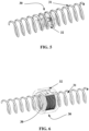
- the radiofrequency transponder of the communication module further comprises a primary antenna electrically connected to the electronic chip, the primary antenna is inductively coupled to the radiating antenna, and the radiating antenna is a dipole antenna consisting of a single-strand helical spring defining the first longitudinal axis.
- the primary antenna is arranged inside the single-strand helical spring of the radiating antenna.
- rubber compound used interchangeably to identify rubber constituents of the tire.
- Cables are said to be inextensible when, under a tensile force equal to 10% of the breaking force, the said cables exhibit a relative elongation of at most 0.2%.
- Cables are said to be elastic when said cables exhibit, under a tensile force equal to the breaking load, a relative elongation at least equal to 3% with a maximum tangent modulus less than 150 GPa.
- Circumferential reinforcing elements are reinforcing elements which make angles with the circumferential direction in the range +2.5°, -2.5° around 0°.
- the circumferential direction of the tire is the direction corresponding to the periphery of the tire and defined by the rolling direction of the tire.
- the transverse or axial direction of the tire is parallel to the tire's axis of rotation.
- the radial direction is a direction intersecting the tire's axis of rotation and perpendicular to it.
- the tire's axis of rotation is the axis around which it rotates during normal use.
- a radial or meridian plane is a plane that contains the tire's axis of rotation.
- the circumferential median plane is a plane perpendicular to the tire's axis of rotation and which divides the tire into two halves.
- the modulus measurements are carried out in tension according to the AFNOR-NFT-46002 standard of September 1988: the nominal secant modulus (or apparent stress, in MPa) is measured in second elongation (i.e., after an accommodation cycle) at 10% elongation (normal temperature and humidity conditions according to the AFNOR-NFT-40101 standard of December 1979).
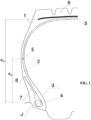
- FIG. 1 represents only a half-view of a tire that extends symmetrically about the circumferential median plane, or equatorial plane, of a tire.
- the turn-up 7 of the carcass reinforcement layer 2 is separated from the main part of the carcass reinforcement layer 2 by a first layer of rubber mixture 9, having a radially outer end 10 at a distance d 10 from point A equal to 117 mm.
- the first layer of rubber mixture 9 has a modulus of elasticity under tension at 10% elongation equal to 7.8 MPa and therefore lower than the modulus of elasticity under tension at 10% elongation of the calendering layers of the carcass reinforcement 2.
Landscapes
- Engineering & Computer Science (AREA)
- Mechanical Engineering (AREA)
- Tires In General (AREA)
Claims (15)
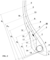
- Reifen (1), der dazu bestimmt ist, auf einer hohlen Felge (J) ("15°-Steilschulterfelge") montiert zu werden, und der eine radiale Karkassenbewehrung (2) aufweist, die aus einer einzigen Karkassenbewehrungsschicht besteht, die von Verstärkungselementen gebildet wird, die zwischen zwei Kalandrierschichten aus Kautschukmischung eingefügt sind, wobei der Reifen (1) eine Scheitelbewehrung (5) aufweist, die ihrerseits radial von einem Laufstreifen (6) bedeckt ist, wobei der Laufstreifen (6) über zwei Seitenwände mit zwei Wülsten (3) verbunden ist, wobei die Schicht von Verstärkungselementen der Karkassenbewehrung (2) in jedem der Wülste (3) durch Umschlag um einen Wulstkern (4) verankert ist, um einen Hauptteil der Karkassenbewehrungsschicht (2), der sich von einem Wulstkern (4) zum anderen erstreckt, und einen umgeschlagenen Teil (7) der Karkassenbewehrungsschicht (2) in jedem der Wülste (3) zu bilden, wobei der umgeschlagene Teil (7) der Karkassenbewehrungsschicht (2) vom Hauptteil der Karkassenbewehrungsschicht (2) durch eine erste Schicht aus Kautschukmischung (9) getrennt ist, die sich radial vom Wulstkern (4) über das Ende (8) des umgeschlagenen Teils (7) der Karkassenbewehrungsschicht (2) hinaus erstreckt, und wobei sich der umgeschlagene Teil (7) der Karkassenbewehrungsschicht (2) axial außen mit einer zweiten Schicht aus Kautschukmischung (11) in Kontakt befindet, die sich ihrerseits wenigstens mit einer dritten Schicht aus Kautschukmischung (14) in Kontakt befindet, die die Außenfläche des Reifens (1) im Bereich des Wulstes bildet, wobei die dritte Schicht aus Kautschukmischung (14) insbesondere dazu bestimmt ist, mit der Felge (J) in Kontakt zu kommen, wobei sich die dritte Schicht aus Kautschukmischung (14) radial außen mit einer vierten Schicht aus Kautschukmischung (16) in Kontakt befindet, welche die Außenfläche der Seitenwand bildet, dadurch gekennzeichnet, dass in einem Meridianschnitt des Reifens:- der Abstand (dR) zwischen dem Ende (8) des umgeschlagenen Teils (7) der Karkassenbewehrungsschicht (2) und dem radial innersten Punkt (A) des dem Wulstkern (4) umbeschriebenen Kreises (T) zwischen 45 und 90 % des Abstands (dE) zwischen dem axial äußersten Punkt (E) des Hauptteils der Karkassenbewehrungsschicht (2) und dem radial innersten Punkt (A) des dem Wulstkern (4) umbeschriebenen Kreises (T) beträgt,- der umgeschlagene Teil (7) der Karkassenbewehrungsschicht (2) und der Hauptteil der Karkassenbewehrungsschicht (2) die einzigen Schichten von Verstärkungselementen, deren Bruchdehnung kleiner als 6 % ist, sind, die in einem Bereich der Seitenwand vorhanden sind, der wenigstens 90 % des Bereichs zwischen dem Ende (8) des umgeschlagenen Teils (7) der Karkassenbewehrungsschicht (2) und dem radial äußersten Punkt (B) des Wulstkerns (4) umfasst,wobei der Reifen dadurch gekennzeichnet ist, dass ein Hochfrequenz-Kommunikationsmodul (20) in dem Wulst (3) an der Schnittstelle zwischen dem umgeschlagene Teil (7) der Karkassenbewehrungsschicht (2) und der zweiten Schicht aus Kautschukmischung (11) angeordnet ist.
- Reifen (1) nach Anspruch 1, wobei die erste Schicht aus Kautschukmischung (9) profiliert ist und der umgeschlagene Teil (7) der Karkassenbewehrungsschicht (2) und der Hauptteil der Karkassenbewehrungsschicht (2) radial außen ab einem Punkt C des umgeschlagenen Teils (7) der Karkassenbewehrungsschicht (2) gekoppelt sind, der sich in einem Abstand befindet, der zwischen 30 und 55 % des Abstands (dR) zwischen dem Ende (8) des umgeschlagenen Teils (7) der Karkassenbewehrungsschicht (2) und dem radial innersten Punkt (A) des dem Wulstkern (4) umbeschriebenen Kreises (T) beträgt, das heißt, dass die jeweiligen Verstärkungselemente des Hauptteils der Karkassenbewehrungsschicht (2) und des umgeschlagene Teils (7) der Karkassenbewehrungsschicht durch eine Dicke der Kautschukmischung getrennt sind, die nicht mehr als 0,5 Millimeter und höchstens 5 Millimeter auf einer Länge, die größer als 15 % des Abstands (dR) ist, variiert, und wobei das Hochfrequenz-Kommunikationsmodul (20) radial außen jenseits des Punktes C angeordnet ist.
- Reifen (1) nach Anspruch 2, wobei radial außen ab dem Punkt C des umgeschlagenen Teils (7) der Karkassenbewehrungsschicht (2) der umgeschlagene Teil (7) der Karkassenbewehrungsschicht (2) und der Hauptteil der Karkassenbewehrungsschicht (2) auf einer Länge gekoppelt sind, die zwischen 15 und 65 % des Abstands (dR) zwischen dem Ende (8) des umgeschlagenen Teils (7) der Karkassenbewehrungsschicht (2) und dem radial innersten Punkt A des dem Wulstkern (4) umbeschriebenen Kreises (T) beträgt, um anschließend durch die erste Schicht aus Kautschukmischung (9) bis zum Ende (8) des umgeschlagenen Teils (7) der Karkassenbewehrungsschicht (2) entkoppelt zu werden, das heißt, dass die Dicke der Kautschukmischung (9), die die jeweiligen Verstärkungselemente des Hauptteils der Karkassenbewehrungsschicht (2) und des umgeschlagenen Teils (7) der Karkassenbewehrungsschicht trennt, größer ist als die Dicke der Kautschukmischung (9) des Kopplungsbereichs, und wobei das Hochfrequenz-Kommunikationsmodul (20) radial gegenüber dem Kopplungsbereich zwischen dem umgeschlagenen Teil (7) und dem Hauptteil der Karkassenbewehrungsschicht (2) angeordnet ist.
- Reifen (1) nach Anspruch 3, wobei die Länge der Entkopplung, das heißt die Länge der Geraden zwischen dem Ende (8) des umgeschlagenen Teils (7) der Karkassenbewehrungsschicht und dem Punkt D, der das radial äußerste Ende des Wulstkerns (2) ist, des Kopplungsbereichs, zwischen 5 und 40 % des Abstands (dR) zwischen dem Ende (8) des umgeschlagenen Teils (7) der Karkassenbewehrungsschicht (2) und dem radial innersten Punkt (A) des dem Wulstkern (4) umbeschriebenen Kreises (T) und vorzugsweise zwischen 15 und 35 % des Abstands (dR) zwischen dem Ende (8) des umgeschlagenen Teils (7) der Karkassenbewehrungsschicht (2) und dem radial innersten Punkt (A) des dem Wulstkern (4) umbeschriebenen Kreises (T) beträgt.
- Reifen (1) nach einem der Ansprüche 2 bis 4, wobei der umgeschlagene Teil (7) der Karkassenbewehrungsschicht (2) und der Hauptteil der Karkassenbewehrungsschicht (2) auf einer Länge gekoppelt sind, die zwischen 25 und 40 % des Abstands (dR) zwischen dem Ende (8) des umgeschlagenen Teils (7) der Karkassenbewehrungsschicht (2) und dem radial innersten Punkt (A) des dem Wulstkern (4) umbeschriebenen Kreises (T) beträgt.
- Reifen (1) nach einem der Ansprüche 2 bis 5, wobei in dem Kopplungsbereich die Dicke der ersten Schicht aus Kautschukmischung (9) im Wesentlichen konstant ist und zwischen 0,8 und 5 mm und vorzugsweise zwischen 2,5 und 3,5 mm beträgt.
- Reifen (1) nach einem der vorhergehenden Ansprüche, wobei das radial innere Ende (13) der zweiten Schicht aus Kautschukmischung (11) radial zwischen dem radial äußersten Punkt (B) des dem Wulstkern (4) umbeschriebenen Kreises (T) und dem radial innersten Punkt (A) des dem Wulstkern (4) umbeschriebenen Kreises (T) liegt.
- Reifen (1) nach einem der vorhergehenden Ansprüche, wobei der Elastizitätsmodul unter Spannung bei 10 % Dehnung der Kalandrierschichten der Karkassenbewehrungsschicht (2) zwischen 4 und 16 MPa und vorzugsweise zwischen 8 und 12 MPa beträgt.
- Reifen (1) nach einem der vorhergehenden Ansprüche, wobei der Elastizitätsmodul unter Spannung bei 10 % Dehnung der ersten Schicht aus Kautschukmischung (9) kleiner oder gleich dem Elastizitätsmodul unter Spannung bei 10 % Dehnung der Kalandrierung der Karkassenbewehrungsschicht (2) ist.
- Reifen (1) nach einem der vorhergehenden Ansprüche, wobei der Elastizitätsmodul unter Spannung bei 10 % Dehnung der ersten Schicht aus Kautschukmischung (9) größer als 50 % des Elastizitätsmoduls unter Spannung bei 10 % Dehnung der Kalandrierung der Karkassenbewehrungsschicht (2) und vorzugsweise größer als 70 % des Elastizitätsmoduls unter Spannung bei 10 % Dehnung der Kalandrierung der Karkassenbewehrungsschicht (2) ist.
- Reifen (1) nach einem der vorhergehenden Ansprüche, wobei der Elastizitätsmodul unter Spannung bei 10 % Dehnung der zweiten Schicht aus Kautschukmischung (11) kleiner als 150 % des Elastizitätsmoduls unter Spannung bei 10 % Dehnung der Kalandrierung der Karkassenbewehrungsschicht (2) ist.
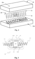
- Reifen (1) nach einem der vorhergehenden Ansprüche, wobei das Kommunikationsmodul (20) aus einem Hochfrequenztransponder (30) besteht, der in eine elektrisch isolierende Umhüllungsgummimasse (22) eingekapselt ist.
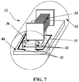
- Reifen (1) nach dem vorhergehenden Anspruch, wobei der Hochfrequenztransponder (30) einen elektronischen Chip (36) aufweist, der mit einer Strahlungsantenne (31) gekoppelt ist, die eine erste Längsachse definiert, wobei die erste Längsachse in dem Koordinatensystem des Reifens in Umfangsrichtung ausgerichtet ist.
- Reifen (1) nach dem vorhergehenden Anspruch, wobei, da die Strahlungsantenne (31) zwei spiralförmige Antennenabschnitte aufweist, der elektronische Chip (36) galvanisch mit den zwei spiralförmigen Antennenabschnitten verbunden ist.
- Reifen (1) nach Anspruch 13, wobei der Hochfrequenztransponder (30) des Kommunikationsmoduls (20) zusätzlich eine Primärantenne (34) aufweist, die elektrisch mit dem elektronischen Chip (36) verbunden ist, wobei die Primärantenne (34) induktiv mit der Strahlungsantenne (31) gekoppelt ist und wobei die Strahlungsantenne (31) eine Dipolantenne ist, die aus einer einsträngigen Spiralfeder besteht, die die erste Längsachse definiert.
Applications Claiming Priority (2)
| Application Number | Priority Date | Filing Date | Title |
|---|---|---|---|
| FR1852350 | 2018-03-20 | ||
| PCT/FR2019/050599 WO2019180357A1 (fr) | 2018-03-20 | 2019-03-18 | Pneumatique poids-lourd equipe d'un module de communication radiofrequence |
Publications (2)
| Publication Number | Publication Date |
|---|---|
| EP3768529A1 EP3768529A1 (de) | 2021-01-27 |
| EP3768529B1 true EP3768529B1 (de) | 2025-07-02 |
Family
ID=63557538
Family Applications (1)
| Application Number | Title | Priority Date | Filing Date |
|---|---|---|---|
| EP19720938.0A Active EP3768529B1 (de) | 2018-03-20 | 2019-03-18 | Mit einem hochfrequenzkommunikationsmodul ausgestattete schwerlastfahrzeugluftreifen |
Country Status (4)
| Country | Link |
|---|---|
| US (1) | US20210016612A1 (de) |
| EP (1) | EP3768529B1 (de) |
| CN (1) | CN111989231B (de) |
| WO (1) | WO2019180357A1 (de) |
Families Citing this family (5)
| Publication number | Priority date | Publication date | Assignee | Title |
|---|---|---|---|---|
| EP3677447B1 (de) * | 2017-09-12 | 2022-07-13 | Sumitomo Rubber Industries, Ltd. | Luftreifen |
| DE112021000298B4 (de) | 2020-02-17 | 2023-07-27 | The Yokohama Rubber Co., Ltd. | Luftreifen |
| JP7448814B2 (ja) * | 2020-05-28 | 2024-03-13 | 横浜ゴム株式会社 | 空気入りタイヤ |
| JP7545046B2 (ja) * | 2020-10-29 | 2024-09-04 | 横浜ゴム株式会社 | 空気入りタイヤ |
| JP2024038880A (ja) * | 2022-09-08 | 2024-03-21 | 株式会社ブリヂストン | タイヤ、未加硫タイヤ、タイヤ製造方法、及び、rfタグ |
Family Cites Families (25)
| Publication number | Priority date | Publication date | Assignee | Title |
|---|---|---|---|---|
| JPS52155702A (en) * | 1976-06-22 | 1977-12-24 | Bridgestone Corp | Radial tyre having improved reinforcing structure at bead section |
| FR2771050B1 (fr) * | 1997-11-14 | 1999-12-24 | Michelin & Cie | Bourrelet sans tringle pour pneumatique |
| JP4107381B2 (ja) * | 2002-08-23 | 2008-06-25 | 横浜ゴム株式会社 | 空気入りタイヤ |
| US20050257868A1 (en) * | 2004-05-21 | 2005-11-24 | Adamson John D | Process and device for incorporating electronics into a tire |
| US8072336B2 (en) * | 2006-02-27 | 2011-12-06 | The Yokohama Rubber Co., Ltd. | Rubber-covered RFID module, and pneumatic tire having the it is embedded |
| FR2914585B1 (fr) * | 2007-04-03 | 2009-07-03 | Michelin Soc Tech | Pneumatique comprenant un organe electronique et procede de fabrication d'un tel pneumatique |
| JP4670880B2 (ja) * | 2008-03-11 | 2011-04-13 | 横浜ゴム株式会社 | 重荷重用空気入りタイヤ |
| US20100122757A1 (en) * | 2008-11-18 | 2010-05-20 | Robert Edward Lionetti | Tire and electronic device assembly |
| FR2956616A1 (fr) * | 2010-02-23 | 2011-08-26 | Michelin Soc Tech | Pneumatique comprenant un organe electronique |
| WO2012030321A1 (en) | 2010-08-30 | 2012-03-08 | Michelin Recherche Et Technique, S.A. | Spring oriented rfid board |
| US20120291936A1 (en) * | 2011-05-19 | 2012-11-22 | Robert Edward Lionetti | Embedded transponder and tire assembly and method of construction thereof |
| FR2999475B1 (fr) * | 2012-12-14 | 2016-12-30 | Michelin & Cie | Bourrelet de pneumatique pour vehicule lourd |
| FR3010655B1 (fr) * | 2013-09-18 | 2015-09-04 | Michelin & Cie | Pneumatique comprenant une armature de renfort de flanc |
| CN105813863B (zh) * | 2013-12-13 | 2018-06-01 | 普利司通美国轮胎运营有限责任公司 | 在下侧壁中具有电子装置的轮胎 |
| JP2015223918A (ja) * | 2014-05-27 | 2015-12-14 | 株式会社ブリヂストン | 電子部品を配置した空気入りタイヤ及びその製造方法 |
| JP6754168B2 (ja) * | 2014-08-08 | 2020-09-09 | 株式会社ブリヂストン | タイヤ |
| JP6423653B2 (ja) * | 2014-09-01 | 2018-11-14 | 株式会社ブリヂストン | タイヤ |
| EP3206895B1 (de) * | 2014-10-16 | 2020-11-18 | Bridgestone Americas Tire Operations, LLC | Reifen mit eingebetteter elektronischer vorrichtung, die mit klebstoff fixiert ist |
| FR3037200B1 (fr) * | 2015-06-03 | 2017-05-26 | Michelin & Cie | Transpondeur radiofrequence pour pneumatique |
| FR3041285B1 (fr) * | 2015-09-18 | 2017-10-27 | Michelin & Cie | Pneumatique possedant un transpondeur passif et procede de communication d'un tel pneumatique |
| FR3050961B1 (fr) * | 2016-05-06 | 2018-04-20 | Compagnie Generale Des Etablissements Michelin | Pneumatique dont la zone du bourrelet est allegee |
| FR3050962B1 (fr) * | 2016-05-06 | 2018-04-20 | Compagnie Generale Des Etablissements Michelin | Pneumatique dont la zone du bourrelet est allegee |
| FR3053930B1 (fr) * | 2016-07-13 | 2018-07-13 | Michelin & Cie | Pneumatique dont la zone du bourrelet est allegee |
| FR3053929B1 (fr) * | 2016-07-13 | 2018-07-13 | Compagnie Generale Des Etablissements Michelin | Pneumatique dont la zone du bourrelet est allegee |
| EP3677447B1 (de) * | 2017-09-12 | 2022-07-13 | Sumitomo Rubber Industries, Ltd. | Luftreifen |
-
2019
- 2019-03-18 CN CN201980026771.9A patent/CN111989231B/zh active Active
- 2019-03-18 US US16/982,283 patent/US20210016612A1/en not_active Abandoned
- 2019-03-18 EP EP19720938.0A patent/EP3768529B1/de active Active
- 2019-03-18 WO PCT/FR2019/050599 patent/WO2019180357A1/fr not_active Ceased
Also Published As
| Publication number | Publication date |
|---|---|
| EP3768529A1 (de) | 2021-01-27 |
| CN111989231A (zh) | 2020-11-24 |
| US20210016612A1 (en) | 2021-01-21 |
| CN111989231B (zh) | 2023-01-13 |
| WO2019180357A1 (fr) | 2019-09-26 |
Similar Documents
| Publication | Publication Date | Title |
|---|---|---|
| EP3768528B1 (de) | Lkw-reifen mit einem hochfrequenzkommunikationsmodul | |
| EP3768529B1 (de) | Mit einem hochfrequenzkommunikationsmodul ausgestattete schwerlastfahrzeugluftreifen | |
| EP3551480B1 (de) | Zum fahren bei einer reifenpanne geeigneter reifen mit einem elektronischen element | |
| EP3762243B1 (de) | Reifen mit einem funkfrequenzkommunikationsmodul | |
| EP4076996B1 (de) | Reifen mit verbessertem wulst | |
| EP3642054B1 (de) | Mit einer elektronischen vorrichtung ausgestatteter reifen mit notlaufeigenschaften | |
| EP3484726B1 (de) | Reifen mit wulstbereich mit reduziertem gewicht | |
| EP3793812B1 (de) | Verfahren zur herstellung eines reifens mit einem radiofrequenzkommunikationsmodul | |
| EP3793845B1 (de) | Reifen für schwerlastkraftwagen, ausgerüstet mit einem radiofrequenzkommunikationsmodul | |
| EP3642055B1 (de) | Notbetrieb-fähiger reifen mit integrieter elektronik | |
| EP3662535B1 (de) | Antenne für ein elektronisches element eines reifens | |
| EP3484728B1 (de) | Reifen mit wulstbereich mit reduziertem gewicht | |
| EP4096936A1 (de) | Optimierte architektur von schwerlastreifen für die landwirtschaft oder den tiefbau | |
| EP4288296A1 (de) | Verfahren zur herstellung eines reifens mit einem leitungsweg | |
| CA3163261A1 (fr) | Architecture optimisee de pneumatique de type poids-lourd, agricole ou genie civil | |
| FR3119566A1 (fr) | Pneumatique presentant un nouveau chemin conducteur |
Legal Events
| Date | Code | Title | Description |
|---|---|---|---|
| STAA | Information on the status of an ep patent application or granted ep patent |
Free format text: STATUS: UNKNOWN |
|
| STAA | Information on the status of an ep patent application or granted ep patent |
Free format text: STATUS: THE INTERNATIONAL PUBLICATION HAS BEEN MADE |
|
| PUAI | Public reference made under article 153(3) epc to a published international application that has entered the european phase |
Free format text: ORIGINAL CODE: 0009012 |
|
| STAA | Information on the status of an ep patent application or granted ep patent |
Free format text: STATUS: REQUEST FOR EXAMINATION WAS MADE |
|
| 17P | Request for examination filed |
Effective date: 20201020 |
|
| AK | Designated contracting states |
Kind code of ref document: A1 Designated state(s): AL AT BE BG CH CY CZ DE DK EE ES FI FR GB GR HR HU IE IS IT LI LT LU LV MC MK MT NL NO PL PT RO RS SE SI SK SM TR |
|
| AX | Request for extension of the european patent |
Extension state: BA ME |
|
| DAV | Request for validation of the european patent (deleted) | ||
| DAX | Request for extension of the european patent (deleted) | ||
| STAA | Information on the status of an ep patent application or granted ep patent |
Free format text: STATUS: EXAMINATION IS IN PROGRESS |
|
| 17Q | First examination report despatched |
Effective date: 20211004 |
|
| GRAP | Despatch of communication of intention to grant a patent |
Free format text: ORIGINAL CODE: EPIDOSNIGR1 |
|
| STAA | Information on the status of an ep patent application or granted ep patent |
Free format text: STATUS: GRANT OF PATENT IS INTENDED |
|
| INTG | Intention to grant announced |
Effective date: 20230509 |
|
| GRAJ | Information related to disapproval of communication of intention to grant by the applicant or resumption of examination proceedings by the epo deleted |
Free format text: ORIGINAL CODE: EPIDOSDIGR1 |
|
| STAA | Information on the status of an ep patent application or granted ep patent |
Free format text: STATUS: EXAMINATION IS IN PROGRESS |
|
| INTC | Intention to grant announced (deleted) | ||
| GRAP | Despatch of communication of intention to grant a patent |
Free format text: ORIGINAL CODE: EPIDOSNIGR1 |
|
| STAA | Information on the status of an ep patent application or granted ep patent |
Free format text: STATUS: GRANT OF PATENT IS INTENDED |
|
| INTG | Intention to grant announced |
Effective date: 20250203 |
|
| GRAS | Grant fee paid |
Free format text: ORIGINAL CODE: EPIDOSNIGR3 |
|
| GRAA | (expected) grant |
Free format text: ORIGINAL CODE: 0009210 |
|
| STAA | Information on the status of an ep patent application or granted ep patent |
Free format text: STATUS: THE PATENT HAS BEEN GRANTED |
|
| AK | Designated contracting states |
Kind code of ref document: B1 Designated state(s): AL AT BE BG CH CY CZ DE DK EE ES FI FR GB GR HR HU IE IS IT LI LT LU LV MC MK MT NL NO PL PT RO RS SE SI SK SM TR |
|
| REG | Reference to a national code |
Ref country code: GB Ref legal event code: FG4D Free format text: NOT ENGLISH |
|
| REG | Reference to a national code |
Ref country code: CH Ref legal event code: EP |
|
| REG | Reference to a national code |
Ref country code: DE Ref legal event code: R096 Ref document number: 602019071905 Country of ref document: DE |
|
| REG | Reference to a national code |
Ref country code: IE Ref legal event code: FG4D Free format text: LANGUAGE OF EP DOCUMENT: FRENCH |
|
| REG | Reference to a national code |
Ref country code: NL Ref legal event code: MP Effective date: 20250702 |
|
| PG25 | Lapsed in a contracting state [announced via postgrant information from national office to epo] |
Ref country code: PT Free format text: LAPSE BECAUSE OF FAILURE TO SUBMIT A TRANSLATION OF THE DESCRIPTION OR TO PAY THE FEE WITHIN THE PRESCRIBED TIME-LIMIT Effective date: 20251103 |
|
| PG25 | Lapsed in a contracting state [announced via postgrant information from national office to epo] |
Ref country code: NL Free format text: LAPSE BECAUSE OF FAILURE TO SUBMIT A TRANSLATION OF THE DESCRIPTION OR TO PAY THE FEE WITHIN THE PRESCRIBED TIME-LIMIT Effective date: 20250702 |
|
| REG | Reference to a national code |
Ref country code: AT Ref legal event code: MK05 Ref document number: 1808849 Country of ref document: AT Kind code of ref document: T Effective date: 20250702 |
|
| PG25 | Lapsed in a contracting state [announced via postgrant information from national office to epo] |
Ref country code: IS Free format text: LAPSE BECAUSE OF FAILURE TO SUBMIT A TRANSLATION OF THE DESCRIPTION OR TO PAY THE FEE WITHIN THE PRESCRIBED TIME-LIMIT Effective date: 20251102 |
|
| PG25 | Lapsed in a contracting state [announced via postgrant information from national office to epo] |
Ref country code: NO Free format text: LAPSE BECAUSE OF FAILURE TO SUBMIT A TRANSLATION OF THE DESCRIPTION OR TO PAY THE FEE WITHIN THE PRESCRIBED TIME-LIMIT Effective date: 20251002 |
|
| REG | Reference to a national code |
Ref country code: LT Ref legal event code: MG9D |
|
| PG25 | Lapsed in a contracting state [announced via postgrant information from national office to epo] |
Ref country code: AT Free format text: LAPSE BECAUSE OF FAILURE TO SUBMIT A TRANSLATION OF THE DESCRIPTION OR TO PAY THE FEE WITHIN THE PRESCRIBED TIME-LIMIT Effective date: 20250702 |
|
| PG25 | Lapsed in a contracting state [announced via postgrant information from national office to epo] |
Ref country code: FI Free format text: LAPSE BECAUSE OF FAILURE TO SUBMIT A TRANSLATION OF THE DESCRIPTION OR TO PAY THE FEE WITHIN THE PRESCRIBED TIME-LIMIT Effective date: 20250702 |
|
| PG25 | Lapsed in a contracting state [announced via postgrant information from national office to epo] |
Ref country code: HR Free format text: LAPSE BECAUSE OF FAILURE TO SUBMIT A TRANSLATION OF THE DESCRIPTION OR TO PAY THE FEE WITHIN THE PRESCRIBED TIME-LIMIT Effective date: 20250702 |
|
| PG25 | Lapsed in a contracting state [announced via postgrant information from national office to epo] |
Ref country code: GR Free format text: LAPSE BECAUSE OF FAILURE TO SUBMIT A TRANSLATION OF THE DESCRIPTION OR TO PAY THE FEE WITHIN THE PRESCRIBED TIME-LIMIT Effective date: 20251003 |
|
| PG25 | Lapsed in a contracting state [announced via postgrant information from national office to epo] |
Ref country code: SE Free format text: LAPSE BECAUSE OF FAILURE TO SUBMIT A TRANSLATION OF THE DESCRIPTION OR TO PAY THE FEE WITHIN THE PRESCRIBED TIME-LIMIT Effective date: 20250702 Ref country code: CZ Free format text: LAPSE BECAUSE OF FAILURE TO SUBMIT A TRANSLATION OF THE DESCRIPTION OR TO PAY THE FEE WITHIN THE PRESCRIBED TIME-LIMIT Effective date: 20250702 |
|
| PG25 | Lapsed in a contracting state [announced via postgrant information from national office to epo] |
Ref country code: LV Free format text: LAPSE BECAUSE OF FAILURE TO SUBMIT A TRANSLATION OF THE DESCRIPTION OR TO PAY THE FEE WITHIN THE PRESCRIBED TIME-LIMIT Effective date: 20250702 |
|
| PG25 | Lapsed in a contracting state [announced via postgrant information from national office to epo] |
Ref country code: BG Free format text: LAPSE BECAUSE OF FAILURE TO SUBMIT A TRANSLATION OF THE DESCRIPTION OR TO PAY THE FEE WITHIN THE PRESCRIBED TIME-LIMIT Effective date: 20250702 Ref country code: PL Free format text: LAPSE BECAUSE OF FAILURE TO SUBMIT A TRANSLATION OF THE DESCRIPTION OR TO PAY THE FEE WITHIN THE PRESCRIBED TIME-LIMIT Effective date: 20250702 |
|
| PG25 | Lapsed in a contracting state [announced via postgrant information from national office to epo] |
Ref country code: RS Free format text: LAPSE BECAUSE OF FAILURE TO SUBMIT A TRANSLATION OF THE DESCRIPTION OR TO PAY THE FEE WITHIN THE PRESCRIBED TIME-LIMIT Effective date: 20251002 |
|
| PG25 | Lapsed in a contracting state [announced via postgrant information from national office to epo] |
Ref country code: ES Free format text: LAPSE BECAUSE OF FAILURE TO SUBMIT A TRANSLATION OF THE DESCRIPTION OR TO PAY THE FEE WITHIN THE PRESCRIBED TIME-LIMIT Effective date: 20250702 |