EP3768525B1 - Solid tyre provided with cushioning holes, - Google Patents
Solid tyre provided with cushioning holes, Download PDFInfo
- Publication number
- EP3768525B1 EP3768525B1 EP18731533.8A EP18731533A EP3768525B1 EP 3768525 B1 EP3768525 B1 EP 3768525B1 EP 18731533 A EP18731533 A EP 18731533A EP 3768525 B1 EP3768525 B1 EP 3768525B1
- Authority
- EP
- European Patent Office
- Prior art keywords
- holes
- tyre
- resilient
- lateral surface
- resilient tyre
- Prior art date
- Legal status (The legal status is an assumption and is not a legal conclusion. Google has not performed a legal analysis and makes no representation as to the accuracy of the status listed.)
- Active
Links
Images




Classifications
-
- B—PERFORMING OPERATIONS; TRANSPORTING
- B60—VEHICLES IN GENERAL
- B60C—VEHICLE TYRES; TYRE INFLATION; TYRE CHANGING; CONNECTING VALVES TO INFLATABLE ELASTIC BODIES IN GENERAL; DEVICES OR ARRANGEMENTS RELATED TO TYRES
- B60C7/00—Non-inflatable or solid tyres
- B60C7/10—Non-inflatable or solid tyres characterised by means for increasing resiliency
- B60C7/107—Non-inflatable or solid tyres characterised by means for increasing resiliency comprising lateral openings
-
- B—PERFORMING OPERATIONS; TRANSPORTING
- B60—VEHICLES IN GENERAL
- B60C—VEHICLE TYRES; TYRE INFLATION; TYRE CHANGING; CONNECTING VALVES TO INFLATABLE ELASTIC BODIES IN GENERAL; DEVICES OR ARRANGEMENTS RELATED TO TYRES
- B60C7/00—Non-inflatable or solid tyres
- B60C7/10—Non-inflatable or solid tyres characterised by means for increasing resiliency
Definitions
- the present invention relates to a solid tyre for industrial and construction applications provided with particular holes designed to reduce transmission of vibrations to the operator.
- a known type of solid tyres are resilient tyres, which are structurally made up of a plurality of circular layers of elastic material set on top of one another in the radial direction, said layers typically forming, proceeding from the centre of the tyre towards the periphery, at least one inner portion referred to as “base” and one outer portion referred to as "tread”.
- Resilient tyres are used on many types of construction machines, industrial vehicles, dollies, and trailers. In particular, they are widely used in machines for moving materials, such as loaders, since these tyres are very resistant to puncturing. Consider, for example, construction and industrial applications that require management of metal waste, which frequently presents cutting edges and would puncture inflated tyres.
- known resilient tyres are obtained with a mix of materials with a high hardness, typically 85 ⁇ 10 Sh A for the base (where Sh is the unit of measurement of the Shore scale for testing the hardness of elastomers) and 70 ⁇ 5 Sh A for the tread.
- a resilient solid tyre that comprises a tread obtained with a mix that has a hardness of between 45 and 65 Sh A, and a plurality of cushioning holes made in at least one of the lateral surfaces of the resilient tyre. Thanks to the aforesaid hardness and the cushioning holes, the effects of the vibrations and of the impact transferred to the operator are considerably reduced.
- a hardness of the tread of between 45 and 65 Sh A entails a fast deterioration of the tread and a consequent reduction of the service life of the resilient tyre.
- the aim of the present invention is to provide a resilient solid tyre with improved cushioning properties and, hence, in which there is an increase in the capacity for absorption of vibrations and impact on the driver.
- a further aim of the present invention is to provide a resilient tyre that will moreover present a longer duration and, hence, a better resistance to deterioration.
- the aforesaid aims are achieved by a resilient solid tyre according to Claim 1.
- a resilient solid tyre according to the present invention is designated as a whole by the reference number 1.
- the resilient tyre 1 is configured for being used in construction and industrial applications on many types of vehicles such as means for moving materials.
- loaders which are machines used for moving material, such as building rubble or industrial waste of any type (for example, metals), in order to displace it and load it onto lorries, which then convey it to the final dump.
- the resilient tyre 1 comprises a plurality of circular layers of elastic material set on top of one another in the radial direction, said layers forming, proceeding from the centre of the resilient tyre towards the periphery, an inner portion referred to as base 2, an outer portion referred to as tread 3, and two lateral surfaces (or sides) 4, 4' of height Q.
- the height Q is also known as "section height”.
- the base 2 is the portion of the tyre 1 that is mounted around the rim, which is in turn rendered fixed with respect to the axle that sets the wheel in rotation.
- the base 2 has a hardness of 80 ⁇ 15 Sh A (where Sh is the unit of measurement of the Shore scale for testing the hardness of elastomers).
- the tread 3, instead, is the portion of the structure of the resilient tyre 1 that comes into contact with the ground on which the wheel turns.
- the tread 3 may be smooth or else may be provided with grooves the number, shape, and depth of which vary according to the use to which the tyre is put.
- the resilient tyre 1 comprises a plurality of cushioning holes 7 made in both of the lateral surfaces 4, 4' of the resilient tyre 1, said holes 7 being designed to function as suspension of the construction machine in order to reduce the effects of repeated vibrations and impacts caused by the vehicle on the operator.
- Figure 1 shows only the holes 7 made in the lateral surface 4, whereas, in a desired way, the holes 7 made in the other lateral surface, i.e., the surface 4', are not illustrated. However, as has already been said and as shown in Figures 5 and 6 , the holes are made in both of the lateral surfaces 4, 4' of the resilient tyre 1.
- a cartesian reference system X, Y, Z will here be adopted, where the axis Z is parallel to the axis of rotation of the tyre 1, and the axes X, Y, orthogonal to the axis Z, represent the plane of the lateral surfaces 4, 4' of the tyre 1.
- the holes 7 have substantially a wing-like shape.
- each hole 7 has an oblong shape that, starting from the aperture made in the lateral surface 4, 4', tapers towards the inside of the tyre 1.
- each hole 7 has transverse dimensions that decrease proceeding, in the direction of the axis Z, from the lateral surface 4, 4' towards the inside of the tyre 1.
- the hole 7 may comprise a first portion 13, in the proximity of the lateral surface 4, 4', and a second portion 14, which is more internal, said first portion 13 being tapered with a decrease per unit length along the axis Z that is the same as, or faster than, that of the second portion 14 (as is, for example, shown in Figure 2 ).
- each hole 7 has substantially the shape of the aperture made in the lateral surface 4, 4', being, however, smaller than said aperture.
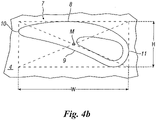
- each hole 7 present in the lateral surfaces 4, 4' hence has substantially the shape of a wing profile comprising an upper camber 8, a lower camber 9, a top edge 10, and a bottom edge 11 ( Figure 4b ).
- each hole 7 can moreover be inscribed in a rectangle lying in the plane X-Y and having height H, base W, and diagonals such as to intersect in a point M (geometrically known as "centre of the rectangle").
- the phrase "inscribed in a rectangle” means that said rectangle is simultaneously tangential to the upper camber 8, to the lower camber 9, to the top edge 10, and to the bottom edge 11 of the aperture.
- said height H of the rectangle is 20% of the section height Q of the lateral surfaces 4, 4' of the resilient tyre 1
- the base W of the rectangle is 50% of the section height Q of the lateral surfaces 4, 4' of the resilient tyre 1.
- the holes 7 are at the same distance apart from one another, arranged radially with respect to the axis of rotation of the tyre 1 ( Figure 3 ).
- the holes 7 made in one lateral surface 4 and the holes 7 made in the other lateral surface 4' are set alongside one another, but oriented with the respective top edges 10 facing in opposite directions.
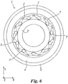
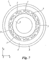
- Figure 7 shows, instead, a second embodiment of the resilient tyre 1 in which the holes 7 made in one lateral surface 4 are offset by half of the pitch 12 with respect to the holes 7 made in the other lateral surface 4'.
- the offset of the holes 7 present in one surface 4 with respect to the holes 7 present in the other surface 4' may differ by half of the pitch 12.
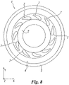
- the holes 7 made in one lateral surface 4 are specular to the holes 7 made in the other lateral surface 4'. In fact, the holes 7 made in one lateral surface 4 and the holes 7 made in the other lateral surface 4' are superimposed in the view of Figure 8 .
- the holes 7 made in one lateral surface 4 are once again specular and moreover offset by half of the pitch 12 with respect to the holes 7 made in the other lateral surface 4'. Also in this case, the offset of the holes 7 present in one surface 4 with respect to the holes 7 present in the other surface 4' may differ by half of the pitch 12.
- the shape of the aperture of each hole 7 may be described with reference to the pitch 12 of the resilient tyre 1.
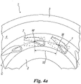
- pitch is understood the distance between two apertures adjacent to one another measured on an imaginary circumference C passing through the points M. Consequently, the pitch is to be understood as the measurement of the arc between the points M of two adjacent apertures, as shown in Figure 4a .
- the aperture of each hole 7 has an upper camber 8 with a length of a value comprised between 40% and 90% of the length of the pitch 12, and a lower camber 9 with a length of a value comprised between 25% and 75% of the length of the pitch 12.
- the aperture of each hole 7 comprises an upper camber 8 with a length that is approximately 80% of the length of the pitch 12, and a lower camber 9 with a length that is approximately 65% of the length of the pitch 12.
- each hole 7 has a depth that can reach at most 90% of the width L of the tread 3.
- each hole has a depth equal to 45% of the width L of the tread.
- each hole 7 has a depth of 275 mm.
- the number of holes 7 present in each of the two lateral surfaces 4, 4' of the resilient tyre 1 may be comprised between 8 and 20.
- the resilient tyre 1 comprises 11 holes 7.
- the particular shape of the holes 7 and their dimensions in proportion to those of the resilient tyre 1 enables creation of a cushioning effect irrespective of the hardness of the mix. Consequently, for the tread 3 of the resilient tyre 1 it is even possible to use hard mixes, for example of a hardness of 70 ⁇ 5 Sh A, thus enhancing the properties of resistance to deterioration (or wear).
- the particular shape of the holes 7 is such as to enable the tyre (and in particular the tread 3) to undergo deformation under the weight of the vehicle, thus damping vibrations and impact that have repercussions on the driver.
- the resilient tyre according to the present invention and specifically to the particular shape of the cushioning holes 7 provided at the sides of the tyre, the effects of repeated vibrations and impact on the operator are further limited, and the service life of the tyre is increased.
Landscapes
- Engineering & Computer Science (AREA)
- Mechanical Engineering (AREA)
- Tires In General (AREA)
- Springs (AREA)
Description
- The present invention relates to a solid tyre for industrial and construction applications provided with particular holes designed to reduce transmission of vibrations to the operator.
- As is well known, in industrial and construction applications wheels made of rubber with a solid structure, also referred to as "solid tyres", are frequently used.
- A known type of solid tyres are resilient tyres, which are structurally made up of a plurality of circular layers of elastic material set on top of one another in the radial direction, said layers typically forming, proceeding from the centre of the tyre towards the periphery, at least one inner portion referred to as "base" and one outer portion referred to as "tread".
- Resilient tyres are used on many types of construction machines, industrial vehicles, dollies, and trailers. In particular, they are widely used in machines for moving materials, such as loaders, since these tyres are very resistant to puncturing. Consider, for example, construction and industrial applications that require management of metal waste, which frequently presents cutting edges and would puncture inflated tyres.
- In order to be resistant to punctures, known resilient tyres are obtained with a mix of materials with a high hardness, typically 85±10 Sh A for the base (where Sh is the unit of measurement of the Shore scale for testing the hardness of elastomers) and 70±5 Sh A for the tread.
- However, industrial and construction machines, and in particular loaders, that mount tyres that are so hard, prove uncomfortable for the driver, since such vehicles are not equipped with suspensions. The springs present underneath the driver's seat and the low elasticity offered by the tyres represent in fact the only form of suspension of the vehicle.
- In order to render the resilient tyres softer, the present applicant has already filed the patent application
PCT/IT2017/000242 EP92102627 A1 WO9718959 A1 JP2010058556 A US2002092589 A1 ,WO9605917 A1 WO2008045194 A1 . - However, a hardness of the tread of between 45 and 65 Sh A entails a fast deterioration of the tread and a consequent reduction of the service life of the resilient tyre.
- The aim of the present invention is to provide a resilient solid tyre with improved cushioning properties and, hence, in which there is an increase in the capacity for absorption of vibrations and impact on the driver.
- A further aim of the present invention is to provide a resilient tyre that will moreover present a longer duration and, hence, a better resistance to deterioration.
- According to the present invention, the aforesaid aims are achieved by a resilient solid tyre according to
Claim 1. - The characteristics and advantages of the present invention will emerge clearly from the ensuing detailed description of a practical embodiment thereof, which is illustrated by way of non-limiting example in the annexed drawings, wherein:
-
Figure 1 is a perspective view of a resilient tyre according to the present invention; -
Figure 2 shows the detail of a hole comprised in the resilient tyre ofFigure 1 ; -
Figure 3 shows a front view of the resilient tyre ofFigure 1 ; -
Figure 4a shows a detail of the view ofFigure 3 ; -
Figure 4b shows a front view of a hole comprised in the resilient tyre ofFigure 1 ; -
Figure 5 shows a side view of the resilient tyre ofFigure 1 ; and -
Figures 6-9 show further front views of different embodiments of the resilient tyre according to the present invention. - With reference to
Figure 1 , a resilient solid tyre according to the present invention is designated as a whole by thereference number 1. - The
resilient tyre 1 is configured for being used in construction and industrial applications on many types of vehicles such as means for moving materials. In particular, among such means, there are loaders, which are machines used for moving material, such as building rubble or industrial waste of any type (for example, metals), in order to displace it and load it onto lorries, which then convey it to the final dump. - Structurally, with reference to
Figure 3 , theresilient tyre 1 comprises a plurality of circular layers of elastic material set on top of one another in the radial direction, said layers forming, proceeding from the centre of the resilient tyre towards the periphery, an inner portion referred to asbase 2, an outer portion referred to astread 3, and two lateral surfaces (or sides) 4, 4' of height Q. The height Q is also known as "section height". - In particular, the
base 2 is the portion of thetyre 1 that is mounted around the rim, which is in turn rendered fixed with respect to the axle that sets the wheel in rotation. Preferably, thebase 2 has a hardness of 80±15 Sh A (where Sh is the unit of measurement of the Shore scale for testing the hardness of elastomers). Thetread 3, instead, is the portion of the structure of theresilient tyre 1 that comes into contact with the ground on which the wheel turns. - The
tread 3 may be smooth or else may be provided with grooves the number, shape, and depth of which vary according to the use to which the tyre is put. - Moreover, the
resilient tyre 1 comprises a plurality ofcushioning holes 7 made in both of thelateral surfaces 4, 4' of theresilient tyre 1, saidholes 7 being designed to function as suspension of the construction machine in order to reduce the effects of repeated vibrations and impacts caused by the vehicle on the operator. - To facilitate understanding by the person skilled in the sector,
Figure 1 shows only theholes 7 made in thelateral surface 4, whereas, in a desired way, theholes 7 made in the other lateral surface, i.e., the surface 4', are not illustrated. However, as has already been said and as shown inFigures 5 and6 , the holes are made in both of thelateral surfaces 4, 4' of theresilient tyre 1. - To further clarify the description of the
resilient tyre 1, according to the present invention, a cartesian reference system X, Y, Z will here be adopted, where the axis Z is parallel to the axis of rotation of thetyre 1, and the axes X, Y, orthogonal to the axis Z, represent the plane of thelateral surfaces 4, 4' of thetyre 1. - As shown more clearly in
Figure 2 , theholes 7 have substantially a wing-like shape. - Moreover, each
hole 7 has an oblong shape that, starting from the aperture made in thelateral surface 4, 4', tapers towards the inside of thetyre 1. In other words, eachhole 7 has transverse dimensions that decrease proceeding, in the direction of the axis Z, from thelateral surface 4, 4' towards the inside of thetyre 1. - The
hole 7 may comprise afirst portion 13, in the proximity of thelateral surface 4, 4', and asecond portion 14, which is more internal, saidfirst portion 13 being tapered with a decrease per unit length along the axis Z that is the same as, or faster than, that of the second portion 14 (as is, for example, shown inFigure 2 ). - Consequently, the end of each
hole 7 has substantially the shape of the aperture made in thelateral surface 4, 4', being, however, smaller than said aperture. - The aperture of each
hole 7 present in thelateral surfaces 4, 4' hence has substantially the shape of a wing profile comprising anupper camber 8, a lower camber 9, atop edge 10, and a bottom edge 11 (Figure 4b ). - The aperture of each
hole 7 can moreover be inscribed in a rectangle lying in the plane X-Y and having height H, base W, and diagonals such as to intersect in a point M (geometrically known as "centre of the rectangle"). The phrase "inscribed in a rectangle" means that said rectangle is simultaneously tangential to theupper camber 8, to the lower camber 9, to thetop edge 10, and to thebottom edge 11 of the aperture. - According to the invention, said height H of the rectangle is 20% of the section height Q of the
lateral surfaces 4, 4' of theresilient tyre 1, and the base W of the rectangle is 50% of the section height Q of thelateral surfaces 4, 4' of theresilient tyre 1. - For each of the
lateral surfaces 4, 4' theholes 7 are at the same distance apart from one another, arranged radially with respect to the axis of rotation of the tyre 1 (Figure 3 ). - In a first embodiment of the
resilient tyre 1 shown inFigure 6 , theholes 7 made in onelateral surface 4 and theholes 7 made in the other lateral surface 4' are set alongside one another, but oriented with the respectivetop edges 10 facing in opposite directions. -
Figure 7 shows, instead, a second embodiment of theresilient tyre 1 in which theholes 7 made in onelateral surface 4 are offset by half of thepitch 12 with respect to theholes 7 made in the other lateral surface 4'. However, the offset of theholes 7 present in onesurface 4 with respect to theholes 7 present in the other surface 4' may differ by half of thepitch 12. - In a third embodiment (
Figure 8 ) theholes 7 made in onelateral surface 4 are specular to theholes 7 made in the other lateral surface 4'. In fact, theholes 7 made in onelateral surface 4 and theholes 7 made in the other lateral surface 4' are superimposed in the view ofFigure 8 . - In a fourth embodiment of the
resilient tyre 1 shown inFigure 9 , theholes 7 made in onelateral surface 4 are once again specular and moreover offset by half of thepitch 12 with respect to theholes 7 made in the other lateral surface 4'. Also in this case, the offset of theholes 7 present in onesurface 4 with respect to theholes 7 present in the other surface 4' may differ by half of thepitch 12. - Alternatively, for greater clarity of description, the shape of the aperture of each
hole 7 may be described with reference to thepitch 12 of theresilient tyre 1. Here, by the term "pitch" is understood the distance between two apertures adjacent to one another measured on an imaginary circumference C passing through the points M. Consequently, the pitch is to be understood as the measurement of the arc between the points M of two adjacent apertures, as shown inFigure 4a . - Using the above reference, the aperture of each
hole 7 has anupper camber 8 with a length of a value comprised between 40% and 90% of the length of thepitch 12, and a lower camber 9 with a length of a value comprised between 25% and 75% of the length of thepitch 12. Preferably, the aperture of eachhole 7 comprises anupper camber 8 with a length that is approximately 80% of the length of thepitch 12, and a lower camber 9 with a length that is approximately 65% of the length of thepitch 12. - Moreover, each
hole 7 has a depth that can reach at most 90% of the width L of thetread 3. Preferably, each hole has a depth equal to 45% of the width L of the tread. - For example, in a
resilient tyre 1 having a radius R of 815 mm, a section height Q of thelateral surfaces 4, 4' of 500 mm, and a width L of 610 mm, eachhole 7 has a depth of 275 mm. - The number of
holes 7 present in each of the twolateral surfaces 4, 4' of theresilient tyre 1 may be comprised between 8 and 20. Preferably, theresilient tyre 1 comprises 11holes 7. - The particular shape of the
holes 7 and their dimensions in proportion to those of theresilient tyre 1 enables creation of a cushioning effect irrespective of the hardness of the mix. Consequently, for thetread 3 of theresilient tyre 1 it is even possible to use hard mixes, for example of a hardness of 70±5 Sh A, thus enhancing the properties of resistance to deterioration (or wear). - In the case of numerous vehicles, such as loaders, the particular shape of the
holes 7 is such as to enable the tyre (and in particular the tread 3) to undergo deformation under the weight of the vehicle, thus damping vibrations and impact that have repercussions on the driver. - Thanks to the resilient tyre according to the present invention, and specifically to the particular shape of the cushioning holes 7 provided at the sides of the tyre, the effects of repeated vibrations and impact on the operator are further limited, and the service life of the tyre is increased.
Claims (10)
- A resilient tyre (1) designed to be used on industrial and construction machinery, said resilient tyre (1) comprising a plurality of circular layers of elastic material set on top of one another in the radial direction, said layers forming, proceeding from the centre of the resilient tyre (1) towards the periphery, an inner portion referred to as base (2), an outer portion referred to as tread (3), and two lateral surfaces (4, 4') with height (Q), said resilient tyre (1) comprising a plurality of cushioning holes (7) made in both of the lateral surfaces (4, 4') of the resilient tyre (1), wherein said cushioning holes (7) substantially have a wing-like shape, wherein the aperture of each cushioning hole (7) in the lateral surface (4, 4') has a wing profile comprising an upper camber (8), a lower camber (9), a top edge (10), and a bottom edge (11), wherein said aperture can be inscribed in a rectangle having a height (H) and a base (W) in such a way that said rectangle is simultaneously tangential to the upper camber (8), to the lower camber (9), to the top edge (10) and to the bottom edge (11) of said aperture, said resilient tyre (1) being characterized in that said height (H) is 20% of the section height (Q) of the lateral surfaces (4, 4'), whereas said base (W) is 50% of the section height (Q) of the lateral surfaces (4, 4').
- The resilient tyre (1) according to claim 1, characterized in that each hole (7) has an oblong shape, which, starting from the aperture made in the lateral surface (4, 4') tapers towards the inside of the tyre (1).
- The resilient tyre (1) according to claim 2, characterized in that said hole (7) comprises a first portion (13), in the proximity of the lateral surface, and a second portion (14), which is more internal, said first portion (13) being tapered with a decrease per unit length that is the same as, or faster than, that of the second portion (14).
- The resilient tyre (1) according to any one of the preceding claims, characterized in that it comprises a number of holes (7) comprised between 8 and 20.
- The resilient tyre (1) according to claim 4, characterized in that it comprises 11 holes (7).
- The resilient tyre (1) according to any one of the preceding claims, characterized in that each hole (7) has a depth that can reach at most 90% of the width (L) of the tread (3).
- The resilient tyre (1) according to any claims 1 to 6, characterized in that the holes (7) made in one lateral surface (4) and the holes (7) made in the other lateral surface (4') are set alongside one another, but oriented with the respective top edges (10) facing in opposite directions.
- The resilient tyre (1) according to any claims 1 to 6, characterized in that the holes (7) made in one lateral surface (4) are specular to the holes (7) made in the other lateral surface (4').
- The resilient tyre (1) according to claim 7 or 8, characterized in that the holes (7) made in one lateral surface (4) are offset in the circumferential direction of the tyre (1) with respect to the holes (7) made in the other lateral surface (4').
- The resilient tyre (1) according to claim 9, characterized in that the diagonals of said rectangle intersect in a point (M), wherein a pitch (12) is the distance between two apertures adjacent to one another measured on an imaginary circumference (C) passing through the points (M), and wherein the holes (7) made in one lateral surface (4) are offset in the circumferential direction of the tyre (1) by half of the pitch (12) with respect to the holes (7) made in the other lateral surface (4').
Applications Claiming Priority (1)
| Application Number | Priority Date | Filing Date | Title |
|---|---|---|---|
| PCT/IT2018/000044 WO2019180750A1 (en) | 2018-03-23 | 2018-03-23 | Solid tyre provided with cushioning holes |
Publications (2)
| Publication Number | Publication Date |
|---|---|
| EP3768525A1 EP3768525A1 (en) | 2021-01-27 |
| EP3768525B1 true EP3768525B1 (en) | 2022-10-19 |
Family
ID=62620917
Family Applications (1)
| Application Number | Title | Priority Date | Filing Date |
|---|---|---|---|
| EP18731533.8A Active EP3768525B1 (en) | 2018-03-23 | 2018-03-23 | Solid tyre provided with cushioning holes, |
Country Status (8)
| Country | Link |
|---|---|
| US (1) | US11731458B2 (en) |
| EP (1) | EP3768525B1 (en) |
| JP (1) | JP7083068B2 (en) |
| CN (1) | CN111936322B (en) |
| BR (1) | BR112020016072B1 (en) |
| RU (1) | RU2758560C1 (en) |
| TW (1) | TWI786256B (en) |
| WO (1) | WO2019180750A1 (en) |
Families Citing this family (4)
| Publication number | Priority date | Publication date | Assignee | Title |
|---|---|---|---|---|
| WO2021090300A1 (en) * | 2019-11-10 | 2021-05-14 | Galileo Wheel Ltd. | Run-flat and airless tires |
| GB2587247B (en) * | 2020-01-24 | 2021-10-06 | Tree Ass Ltd | Tyre |
| US12611078B2 (en) | 2022-08-22 | 2026-04-28 | Samsung Electronics Co., Ltd. | Robot cleaner |
| WO2024043596A1 (en) * | 2022-08-22 | 2024-02-29 | 삼성전자주식회사 | Robot cleaner |
Family Cites Families (19)
| Publication number | Priority date | Publication date | Assignee | Title |
|---|---|---|---|---|
| US1237227A (en) * | 1917-04-05 | 1917-08-14 | John L Swartz | Cushion-tire and method of making the same. |
| CA1032455A (en) * | 1975-05-06 | 1978-06-06 | William O. Sassaman | Molded integral flat-proof tire and method of making |
| AR240776A1 (en) * | 1986-12-23 | 1991-02-28 | Fuglini Roberto Angel | A SOLID TIRE FOR A BICYCLE OR THE LIKE |
| CA2043082A1 (en) * | 1991-02-27 | 1992-08-28 | James Edward Duddey | Non-pneumatic spare tire |
| CN1154582C (en) | 1994-08-19 | 2004-06-23 | 福山护谟工业株式会社 | Ground-engaging apparatus |
| JP2000515452A (en) | 1995-11-20 | 2000-11-21 | エアボス タイヤズ ピィーティーワイ リミティッド | Rotatable grounding structure |
| JP4072708B2 (en) | 2000-12-28 | 2008-04-09 | 福山ゴム工業株式会社 | Cushion tire |
| CN1798662B (en) * | 2003-02-05 | 2012-06-20 | 福山橡胶工业株式会社 | Non-pneumatic tire |
| US7174936B2 (en) * | 2003-12-22 | 2007-02-13 | Caterpillar Inc | Solid suspended work machine tire |
| ITTO20040120A1 (en) * | 2004-02-27 | 2004-05-27 | Fiat Auto Spa | TIRE FOR VEHICLES, IN PARTICULAR, VEHICLES |
| US20070029020A1 (en) * | 2004-06-09 | 2007-02-08 | Caterpillar Inc. | Solid suspended tire |
| US8826953B2 (en) | 2008-03-11 | 2014-09-09 | Artic Investments S.A. | Wheel, rim and tire |
| JP5441147B2 (en) * | 2008-09-01 | 2014-03-12 | 福山ゴム工業株式会社 | Non-pneumatic tire |
| KR20100102823A (en) * | 2009-03-12 | 2010-09-27 | 김종경 | A tubeless tire having elliptically cylindrical elastic members |
| JP5597476B2 (en) | 2010-08-11 | 2014-10-01 | 住友ゴム工業株式会社 | Solid tire |
| KR20160001394A (en) * | 2014-06-27 | 2016-01-06 | 에브리봇 주식회사 | Tire for improving grip force mounted movable electronics |
| CN104802602B (en) * | 2015-05-15 | 2017-02-22 | 杨雪云 | Automatic radiating type inflating-free hollow tire |
| CN206544437U (en) | 2017-03-20 | 2017-10-10 | 张传友 | Non-inflatable tyre |
| GB2587247B (en) * | 2020-01-24 | 2021-10-06 | Tree Ass Ltd | Tyre |
-
2018
- 2018-03-23 RU RU2020132613A patent/RU2758560C1/en active
- 2018-03-23 JP JP2021500375A patent/JP7083068B2/en active Active
- 2018-03-23 EP EP18731533.8A patent/EP3768525B1/en active Active
- 2018-03-23 BR BR112020016072-5A patent/BR112020016072B1/en active IP Right Grant
- 2018-03-23 WO PCT/IT2018/000044 patent/WO2019180750A1/en not_active Ceased
- 2018-03-23 CN CN201880090613.5A patent/CN111936322B/en active Active
- 2018-03-23 US US16/982,652 patent/US11731458B2/en active Active
-
2019
- 2019-01-14 TW TW108101305A patent/TWI786256B/en active
Also Published As
| Publication number | Publication date |
|---|---|
| WO2019180750A1 (en) | 2019-09-26 |
| US20210178815A1 (en) | 2021-06-17 |
| EP3768525A1 (en) | 2021-01-27 |
| TWI786256B (en) | 2022-12-11 |
| CN111936322B (en) | 2023-01-17 |
| JP7083068B2 (en) | 2022-06-09 |
| CN111936322A (en) | 2020-11-13 |
| BR112020016072A2 (en) | 2020-12-08 |
| US11731458B2 (en) | 2023-08-22 |
| JP2021519721A (en) | 2021-08-12 |
| RU2758560C1 (en) | 2021-10-29 |
| TW201940354A (en) | 2019-10-16 |
| BR112020016072B1 (en) | 2023-03-14 |
Similar Documents
| Publication | Publication Date | Title |
|---|---|---|
| EP3768525B1 (en) | Solid tyre provided with cushioning holes, | |
| KR102581110B1 (en) | Airless tire | |
| US10112442B2 (en) | Non-pneumatic tire | |
| EP0205233B1 (en) | Pneumatic tyre | |
| JP5597476B2 (en) | Solid tire | |
| EP0691220A2 (en) | A pneumatic tire for use on agricultural tractors and other like vehicles | |
| US6651712B1 (en) | Variable pitched tread for ATV tire | |
| WO2020076507A1 (en) | Nonpneumatic tire having multiple shear hoops | |
| AU2015293163B2 (en) | Heavy duty pneumatic tire | |
| EP3300927B1 (en) | Heavy duty tire and tread | |
| KR102656639B1 (en) | Non-pneumatic tire | |
| KR102288484B1 (en) | Non-pneumatic tire | |
| EP1192053B1 (en) | Variable pitched tread for atv tire | |
| JP2014177230A (en) | Pneumatic tire for agricultural machine | |
| WO2019087218A1 (en) | Solid tyre for industrial and construction applications | |
| CN116323254B (en) | Tires with a tread made of a blend of various elastomers | |
| JP7567266B2 (en) | Airless tires | |
| JP2008114756A (en) | Tire for agricultural machine | |
| JP5823795B2 (en) | Heavy duty pneumatic radial tire | |
| JP2009280086A (en) | Lug tire | |
| JPH02127105A (en) | Tire for automobile | |
| EP3466724A1 (en) | Heavy load tire | |
| WO2022024541A1 (en) | Stud pin and tire comprising same | |
| JP2016005935A (en) | Pneumatic tire | |
| JP2012056424A (en) | Tire |
Legal Events
| Date | Code | Title | Description |
|---|---|---|---|
| STAA | Information on the status of an ep patent application or granted ep patent |
Free format text: STATUS: UNKNOWN |
|
| STAA | Information on the status of an ep patent application or granted ep patent |
Free format text: STATUS: THE INTERNATIONAL PUBLICATION HAS BEEN MADE |
|
| PUAI | Public reference made under article 153(3) epc to a published international application that has entered the european phase |
Free format text: ORIGINAL CODE: 0009012 |
|
| STAA | Information on the status of an ep patent application or granted ep patent |
Free format text: STATUS: REQUEST FOR EXAMINATION WAS MADE |
|
| 17P | Request for examination filed |
Effective date: 20200922 |
|
| AK | Designated contracting states |
Kind code of ref document: A1 Designated state(s): AL AT BE BG CH CY CZ DE DK EE ES FI FR GB GR HR HU IE IS IT LI LT LU LV MC MK MT NL NO PL PT RO RS SE SI SK SM TR |
|
| AX | Request for extension of the european patent |
Extension state: BA ME |
|
| DAV | Request for validation of the european patent (deleted) | ||
| DAX | Request for extension of the european patent (deleted) | ||
| STAA | Information on the status of an ep patent application or granted ep patent |
Free format text: STATUS: EXAMINATION IS IN PROGRESS |
|
| 17Q | First examination report despatched |
Effective date: 20210915 |
|
| GRAP | Despatch of communication of intention to grant a patent |
Free format text: ORIGINAL CODE: EPIDOSNIGR1 |
|
| STAA | Information on the status of an ep patent application or granted ep patent |
Free format text: STATUS: GRANT OF PATENT IS INTENDED |
|
| INTG | Intention to grant announced |
Effective date: 20220609 |
|
| GRAS | Grant fee paid |
Free format text: ORIGINAL CODE: EPIDOSNIGR3 |
|
| GRAA | (expected) grant |
Free format text: ORIGINAL CODE: 0009210 |
|
| STAA | Information on the status of an ep patent application or granted ep patent |
Free format text: STATUS: THE PATENT HAS BEEN GRANTED |
|
| AK | Designated contracting states |
Kind code of ref document: B1 Designated state(s): AL AT BE BG CH CY CZ DE DK EE ES FI FR GB GR HR HU IE IS IT LI LT LU LV MC MK MT NL NO PL PT RO RS SE SI SK SM TR |
|
| REG | Reference to a national code |
Ref country code: GB Ref legal event code: FG4D |
|
| REG | Reference to a national code |
Ref country code: CH Ref legal event code: EP |
|
| REG | Reference to a national code |
Ref country code: DE Ref legal event code: R096 Ref document number: 602018041969 Country of ref document: DE |
|
| REG | Reference to a national code |
Ref country code: IE Ref legal event code: FG4D |
|
| REG | Reference to a national code |
Ref country code: AT Ref legal event code: REF Ref document number: 1525349 Country of ref document: AT Kind code of ref document: T Effective date: 20221115 |
|
| REG | Reference to a national code |
Ref country code: NL Ref legal event code: FP |
|
| REG | Reference to a national code |
Ref country code: SE Ref legal event code: TRGR |
|
| REG | Reference to a national code |
Ref country code: LT Ref legal event code: MG9D |
|
| PG25 | Lapsed in a contracting state [announced via postgrant information from national office to epo] |
Ref country code: PT Free format text: LAPSE BECAUSE OF FAILURE TO SUBMIT A TRANSLATION OF THE DESCRIPTION OR TO PAY THE FEE WITHIN THE PRESCRIBED TIME-LIMIT Effective date: 20230220 Ref country code: NO Free format text: LAPSE BECAUSE OF FAILURE TO SUBMIT A TRANSLATION OF THE DESCRIPTION OR TO PAY THE FEE WITHIN THE PRESCRIBED TIME-LIMIT Effective date: 20230119 Ref country code: LT Free format text: LAPSE BECAUSE OF FAILURE TO SUBMIT A TRANSLATION OF THE DESCRIPTION OR TO PAY THE FEE WITHIN THE PRESCRIBED TIME-LIMIT Effective date: 20221019 Ref country code: FI Free format text: LAPSE BECAUSE OF FAILURE TO SUBMIT A TRANSLATION OF THE DESCRIPTION OR TO PAY THE FEE WITHIN THE PRESCRIBED TIME-LIMIT Effective date: 20221019 Ref country code: ES Free format text: LAPSE BECAUSE OF FAILURE TO SUBMIT A TRANSLATION OF THE DESCRIPTION OR TO PAY THE FEE WITHIN THE PRESCRIBED TIME-LIMIT Effective date: 20221019 |
|
| PG25 | Lapsed in a contracting state [announced via postgrant information from national office to epo] |
Ref country code: RS Free format text: LAPSE BECAUSE OF FAILURE TO SUBMIT A TRANSLATION OF THE DESCRIPTION OR TO PAY THE FEE WITHIN THE PRESCRIBED TIME-LIMIT Effective date: 20221019 Ref country code: PL Free format text: LAPSE BECAUSE OF FAILURE TO SUBMIT A TRANSLATION OF THE DESCRIPTION OR TO PAY THE FEE WITHIN THE PRESCRIBED TIME-LIMIT Effective date: 20221019 Ref country code: LV Free format text: LAPSE BECAUSE OF FAILURE TO SUBMIT A TRANSLATION OF THE DESCRIPTION OR TO PAY THE FEE WITHIN THE PRESCRIBED TIME-LIMIT Effective date: 20221019 Ref country code: IS Free format text: LAPSE BECAUSE OF FAILURE TO SUBMIT A TRANSLATION OF THE DESCRIPTION OR TO PAY THE FEE WITHIN THE PRESCRIBED TIME-LIMIT Effective date: 20230219 Ref country code: HR Free format text: LAPSE BECAUSE OF FAILURE TO SUBMIT A TRANSLATION OF THE DESCRIPTION OR TO PAY THE FEE WITHIN THE PRESCRIBED TIME-LIMIT Effective date: 20221019 Ref country code: GR Free format text: LAPSE BECAUSE OF FAILURE TO SUBMIT A TRANSLATION OF THE DESCRIPTION OR TO PAY THE FEE WITHIN THE PRESCRIBED TIME-LIMIT Effective date: 20230120 |
|
| P01 | Opt-out of the competence of the unified patent court (upc) registered |
Effective date: 20230602 |
|
| REG | Reference to a national code |
Ref country code: DE Ref legal event code: R097 Ref document number: 602018041969 Country of ref document: DE |
|
| PG25 | Lapsed in a contracting state [announced via postgrant information from national office to epo] |
Ref country code: SM Free format text: LAPSE BECAUSE OF FAILURE TO SUBMIT A TRANSLATION OF THE DESCRIPTION OR TO PAY THE FEE WITHIN THE PRESCRIBED TIME-LIMIT Effective date: 20221019 Ref country code: RO Free format text: LAPSE BECAUSE OF FAILURE TO SUBMIT A TRANSLATION OF THE DESCRIPTION OR TO PAY THE FEE WITHIN THE PRESCRIBED TIME-LIMIT Effective date: 20221019 Ref country code: EE Free format text: LAPSE BECAUSE OF FAILURE TO SUBMIT A TRANSLATION OF THE DESCRIPTION OR TO PAY THE FEE WITHIN THE PRESCRIBED TIME-LIMIT Effective date: 20221019 Ref country code: DK Free format text: LAPSE BECAUSE OF FAILURE TO SUBMIT A TRANSLATION OF THE DESCRIPTION OR TO PAY THE FEE WITHIN THE PRESCRIBED TIME-LIMIT Effective date: 20221019 Ref country code: CZ Free format text: LAPSE BECAUSE OF FAILURE TO SUBMIT A TRANSLATION OF THE DESCRIPTION OR TO PAY THE FEE WITHIN THE PRESCRIBED TIME-LIMIT Effective date: 20221019 |
|
| PLBE | No opposition filed within time limit |
Free format text: ORIGINAL CODE: 0009261 |
|
| STAA | Information on the status of an ep patent application or granted ep patent |
Free format text: STATUS: NO OPPOSITION FILED WITHIN TIME LIMIT |
|
| PG25 | Lapsed in a contracting state [announced via postgrant information from national office to epo] |
Ref country code: SK Free format text: LAPSE BECAUSE OF FAILURE TO SUBMIT A TRANSLATION OF THE DESCRIPTION OR TO PAY THE FEE WITHIN THE PRESCRIBED TIME-LIMIT Effective date: 20221019 Ref country code: AL Free format text: LAPSE BECAUSE OF FAILURE TO SUBMIT A TRANSLATION OF THE DESCRIPTION OR TO PAY THE FEE WITHIN THE PRESCRIBED TIME-LIMIT Effective date: 20221019 |
|
| REG | Reference to a national code |
Ref country code: AT Ref legal event code: UEP Ref document number: 1525349 Country of ref document: AT Kind code of ref document: T Effective date: 20221019 |
|
| 26N | No opposition filed |
Effective date: 20230720 |
|
| PG25 | Lapsed in a contracting state [announced via postgrant information from national office to epo] |
Ref country code: MC Free format text: LAPSE BECAUSE OF FAILURE TO SUBMIT A TRANSLATION OF THE DESCRIPTION OR TO PAY THE FEE WITHIN THE PRESCRIBED TIME-LIMIT Effective date: 20221019 |
|
| REG | Reference to a national code |
Ref country code: CH Ref legal event code: PL |
|
| PG25 | Lapsed in a contracting state [announced via postgrant information from national office to epo] |
Ref country code: SI Free format text: LAPSE BECAUSE OF FAILURE TO SUBMIT A TRANSLATION OF THE DESCRIPTION OR TO PAY THE FEE WITHIN THE PRESCRIBED TIME-LIMIT Effective date: 20221019 |
|
| REG | Reference to a national code |
Ref country code: BE Ref legal event code: MM Effective date: 20230331 |
|
| PG25 | Lapsed in a contracting state [announced via postgrant information from national office to epo] |
Ref country code: LU Free format text: LAPSE BECAUSE OF NON-PAYMENT OF DUE FEES Effective date: 20230323 |
|
| REG | Reference to a national code |
Ref country code: IE Ref legal event code: MM4A |
|
| PG25 | Lapsed in a contracting state [announced via postgrant information from national office to epo] |
Ref country code: LI Free format text: LAPSE BECAUSE OF NON-PAYMENT OF DUE FEES Effective date: 20230331 Ref country code: IE Free format text: LAPSE BECAUSE OF NON-PAYMENT OF DUE FEES Effective date: 20230323 Ref country code: CH Free format text: LAPSE BECAUSE OF NON-PAYMENT OF DUE FEES Effective date: 20230331 |
|
| PG25 | Lapsed in a contracting state [announced via postgrant information from national office to epo] |
Ref country code: BE Free format text: LAPSE BECAUSE OF NON-PAYMENT OF DUE FEES Effective date: 20230331 |
|
| PG25 | Lapsed in a contracting state [announced via postgrant information from national office to epo] |
Ref country code: BG Free format text: LAPSE BECAUSE OF FAILURE TO SUBMIT A TRANSLATION OF THE DESCRIPTION OR TO PAY THE FEE WITHIN THE PRESCRIBED TIME-LIMIT Effective date: 20221019 |
|
| PG25 | Lapsed in a contracting state [announced via postgrant information from national office to epo] |
Ref country code: BG Free format text: LAPSE BECAUSE OF FAILURE TO SUBMIT A TRANSLATION OF THE DESCRIPTION OR TO PAY THE FEE WITHIN THE PRESCRIBED TIME-LIMIT Effective date: 20221019 |
|
| PGFP | Annual fee paid to national office [announced via postgrant information from national office to epo] |
Ref country code: SE Payment date: 20250312 Year of fee payment: 8 |
|
| PGFP | Annual fee paid to national office [announced via postgrant information from national office to epo] |
Ref country code: DE Payment date: 20250327 Year of fee payment: 8 |
|
| PGFP | Annual fee paid to national office [announced via postgrant information from national office to epo] |
Ref country code: NL Payment date: 20250327 Year of fee payment: 8 |
|
| PGFP | Annual fee paid to national office [announced via postgrant information from national office to epo] |
Ref country code: AT Payment date: 20250305 Year of fee payment: 8 |
|
| PGFP | Annual fee paid to national office [announced via postgrant information from national office to epo] |
Ref country code: FR Payment date: 20250325 Year of fee payment: 8 |
|
| PGFP | Annual fee paid to national office [announced via postgrant information from national office to epo] |
Ref country code: IT Payment date: 20250224 Year of fee payment: 8 Ref country code: GB Payment date: 20250327 Year of fee payment: 8 |
|
| PG25 | Lapsed in a contracting state [announced via postgrant information from national office to epo] |
Ref country code: CY Free format text: LAPSE BECAUSE OF FAILURE TO SUBMIT A TRANSLATION OF THE DESCRIPTION OR TO PAY THE FEE WITHIN THE PRESCRIBED TIME-LIMIT; INVALID AB INITIO Effective date: 20180323 |
|
| PG25 | Lapsed in a contracting state [announced via postgrant information from national office to epo] |
Ref country code: HU Free format text: LAPSE BECAUSE OF FAILURE TO SUBMIT A TRANSLATION OF THE DESCRIPTION OR TO PAY THE FEE WITHIN THE PRESCRIBED TIME-LIMIT; INVALID AB INITIO Effective date: 20180323 |
|
| PG25 | Lapsed in a contracting state [announced via postgrant information from national office to epo] |
Ref country code: TR Free format text: LAPSE BECAUSE OF FAILURE TO SUBMIT A TRANSLATION OF THE DESCRIPTION OR TO PAY THE FEE WITHIN THE PRESCRIBED TIME-LIMIT Effective date: 20221019 |