EP3768360B1 - Spritzenkolben und kolbenstangenanordnung für eine spritzenbaugruppe - Google Patents
Spritzenkolben und kolbenstangenanordnung für eine spritzenbaugruppe Download PDFInfo
- Publication number
- EP3768360B1 EP3768360B1 EP19714005.6A EP19714005A EP3768360B1 EP 3768360 B1 EP3768360 B1 EP 3768360B1 EP 19714005 A EP19714005 A EP 19714005A EP 3768360 B1 EP3768360 B1 EP 3768360B1
- Authority
- EP
- European Patent Office
- Prior art keywords
- plunger rod
- stopper
- syringe
- syringe barrel
- protrusion
- Prior art date
- Legal status (The legal status is an assumption and is not a legal conclusion. Google has not performed a legal analysis and makes no representation as to the accuracy of the status listed.)
- Active
Links
Images


Classifications
-
- A—HUMAN NECESSITIES
- A61—MEDICAL OR VETERINARY SCIENCE; HYGIENE
- A61M—DEVICES FOR INTRODUCING MEDIA INTO, OR ONTO, THE BODY; DEVICES FOR TRANSDUCING BODY MEDIA OR FOR TAKING MEDIA FROM THE BODY; DEVICES FOR PRODUCING OR ENDING SLEEP OR STUPOR
- A61M5/00—Devices for bringing media into the body in a subcutaneous, intra-vascular or intramuscular way; Accessories therefor, e.g. filling or cleaning devices, arm-rests
- A61M5/178—Syringes
- A61M5/31—Details
- A61M5/3129—Syringe barrels
- A61M5/3135—Syringe barrels characterised by constructional features of the proximal end
-
- A—HUMAN NECESSITIES
- A61—MEDICAL OR VETERINARY SCIENCE; HYGIENE
- A61M—DEVICES FOR INTRODUCING MEDIA INTO, OR ONTO, THE BODY; DEVICES FOR TRANSDUCING BODY MEDIA OR FOR TAKING MEDIA FROM THE BODY; DEVICES FOR PRODUCING OR ENDING SLEEP OR STUPOR
- A61M5/00—Devices for bringing media into the body in a subcutaneous, intra-vascular or intramuscular way; Accessories therefor, e.g. filling or cleaning devices, arm-rests
- A61M5/178—Syringes
- A61M5/31—Details
- A61M5/315—Pistons; Piston-rods; Guiding, blocking or restricting the movement of the rod or piston; Appliances on the rod for facilitating dosing ; Dosing mechanisms
- A61M5/31501—Means for blocking or restricting the movement of the rod or piston
-
- A—HUMAN NECESSITIES
- A61—MEDICAL OR VETERINARY SCIENCE; HYGIENE
- A61M—DEVICES FOR INTRODUCING MEDIA INTO, OR ONTO, THE BODY; DEVICES FOR TRANSDUCING BODY MEDIA OR FOR TAKING MEDIA FROM THE BODY; DEVICES FOR PRODUCING OR ENDING SLEEP OR STUPOR
- A61M5/00—Devices for bringing media into the body in a subcutaneous, intra-vascular or intramuscular way; Accessories therefor, e.g. filling or cleaning devices, arm-rests
- A61M5/178—Syringes
- A61M5/31—Details
- A61M5/315—Pistons; Piston-rods; Guiding, blocking or restricting the movement of the rod or piston; Appliances on the rod for facilitating dosing ; Dosing mechanisms
- A61M5/31511—Piston or piston-rod constructions, e.g. connection of piston with piston-rod
- A61M5/31513—Piston constructions to improve sealing or sliding
-
- A—HUMAN NECESSITIES
- A61—MEDICAL OR VETERINARY SCIENCE; HYGIENE
- A61M—DEVICES FOR INTRODUCING MEDIA INTO, OR ONTO, THE BODY; DEVICES FOR TRANSDUCING BODY MEDIA OR FOR TAKING MEDIA FROM THE BODY; DEVICES FOR PRODUCING OR ENDING SLEEP OR STUPOR
- A61M5/00—Devices for bringing media into the body in a subcutaneous, intra-vascular or intramuscular way; Accessories therefor, e.g. filling or cleaning devices, arm-rests
- A61M5/178—Syringes
- A61M5/31—Details
- A61M5/315—Pistons; Piston-rods; Guiding, blocking or restricting the movement of the rod or piston; Appliances on the rod for facilitating dosing ; Dosing mechanisms
- A61M5/31511—Piston or piston-rod constructions, e.g. connection of piston with piston-rod
- A61M5/31515—Connection of piston with piston rod
-
- A—HUMAN NECESSITIES
- A61—MEDICAL OR VETERINARY SCIENCE; HYGIENE
- A61M—DEVICES FOR INTRODUCING MEDIA INTO, OR ONTO, THE BODY; DEVICES FOR TRANSDUCING BODY MEDIA OR FOR TAKING MEDIA FROM THE BODY; DEVICES FOR PRODUCING OR ENDING SLEEP OR STUPOR
- A61M2205/00—General characteristics of the apparatus
- A61M2205/02—General characteristics of the apparatus characterised by a particular materials
- A61M2205/0216—Materials providing elastic properties, e.g. for facilitating deformation and avoid breaking
Definitions
- the invention relates, in general, to a stopper assembly for use with a syringe and, more particularly, a stopper and plunger rod arrangement for use with a syringe.
- a typical three-piece syringe includes a tubular barrel having an access opening formed at one end, and a smaller discharge opening formed at the opposing end.
- the lead end of an elongated plunger is received within the access opening of the barrel so as to be slidable within the barrel.
- Attached to the lead end of the plunger is a flexible sealing member or stopper that snugly seals against the interior surface of the barrel.
- a needle, a threaded member, or a non-threaded member is usually attached to the discharge opening on the barrel.
- the needle can be used to penetrate a surface while the threaded member can be used to attach the syringe to another medical device, such as a catheter.
- the flexible stopper is usually manufactured from an elastomeric material, such as a rubber or a cross-linked or thermal plastic elastomer.
- a two-piece syringe includes a "stopper" that is in the form of a rigid sealing disc, also known as a plunger rod head. It is typically made of the same rigid plastic as the rest of the plunger rod.
- the sealing force in a two-piece syringe comes from a thin elastic barrel that deforms around the rigid plunger rod head.
- the discharge end of the syringe is initially placed in contact with a fluid.
- a fluid For example, the needle on the syringe can be inserted into a liquid medication.
- a process known as aspiration a negative pressure is formed within the end of the barrel so as to cause the fluid to be drawn into the barrel.
- the syringe can then be moved to a second location where advancing the plunger within the barrel causes the fluid to be pushed or expressed out of the discharge end of the barrel.
- a width of the first contact surface is substantially equal to a width of the first rib, and a width of the second contact surface is substantially equal to a width of the second rib.
- the notch defined in the inner contour provides a reduced thickness of the main body portion from the inner contour to an outer surface of the main body portion.
- the closed front end of the main body portion has a conical shape with a tip.
- a recess is formed on the outer surface of the main body portion between the first rib and the second rib.
- a width of the recess is substantially equal to a width of the notch.
- At least one collapsible cut-out is defined in the inner contour of the inner cavity. The collapsible cut-out permits the stopper to collapse or bend when under pressure.
- the stopper is made of a thermal plastic elastomer.
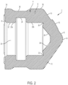
- a first aspect of the stopper 2 includes a main body portion 4 defining an open rearward end 6 configured to receive a plunger rod and a closed front end 8 that forms a flexible roof.
- the stopper 2 is made of a thermal plastic elastomer. It is also contemplated that the stopper 2 is made of any alternative hard or soft plastic.
- the closed front end 8 of the main body portion 4 includes a substantially cylindrical portion 9, a first angled portion 10 and a second angled portion 12, which are both part of a single conical surface, that extend toward a tip 14, thereby providing the closed front end 8 with a substantially conical appearance.
- this shape of the flexible roof is not to be considered as limiting the present invention as the roof may be flat. Such a roof would not provide flexing roof action in which a flexible roof of the stopper flexes inward and expands sideways in a radial direction.
- at least dimple 16, 18 extends from an outer surface of the first angled portion 10 and the second angled portion 12 of the closed front end 8. Dimples 16, 18 are designed to keep the stopper 2 from making contact with a front portion of the syringe barrel for preventing reflux flow at the end of an injection procedure. Although only one dimple 16, 18 is shown extending from the first angled portion 10 and the second angled portion 12, it is contemplated that additional features may be provided on these surfaces or no dimples may be provided on these surfaces.
- the main body portion 4 of the stopper 2 is substantially hollow and designed to receive an attachment portion of a plunger rod, as described below.
- the main body portion 4 of the stopper 2 defines an inner cavity 20 that receives the attachment portion of the plunger rod.
- the inner cavity 20 is defined between the rearward end 6 and the closed front end 8 of the main body portion 4.
- the inner cavity 20 defines an inner contour 22 in the main body portion 4.
- the inner contour 22 defines a notch 24 configured to receive a portion of the attachment portion of the plunger rod to retain the attachment portion within the inner cavity 20.
- the notch 24 is defined in the cylindrical portion 9 of the main body portion 4 and extends outwardly from the inner surface of the inner cavity 20 and around the circumferential surface of the inner contour 22.
- the notch 24 defined in the inner contour 22 defines a reduced thickness of the main body portion 4 from the inner contour 22 to the outer surface of the main body portion 4 as compared to the thickness in the remaining portion of the main body portion 4.
- the notch 24 is defined between a first contact surface 25a and a second contact surface 25b of the inner contour 22.
- the reduction in thickness of the cylindrical portion 9 assists in reducing plunger rod misalignment loading forces transferring to the stopper rib contact surfaces.
- the inner contour 22 of the inner cavity 20 also defines a first angled portion 26 and a second angled portion 28 in the front end 8 of the stopper 2 that correspond to the first angled portion 10 and the second angled portion 12 of the outer surface of the front end 8.
- the first angled portion 26 and the second angled portion 28 which are both part of a single conical surface, provide the inner surface of the closed front end 8 with a substantially conical appearance.
- Adjacent the first angled portion 26 and the second angled portion 28, a pair of collapsible cut-outs 30, 32 are defined in the inner contour 22.
- the collapsible cut-outs 30, 32 are notches or recesses defined in the inner contour 22 of the main body portion 4.
- the collapsible cut-outs 30, 32 are provided to allow the adjacent portions of the main body portion 4 to bend radially outward when the stopper is under fluid pressure, which causes the flexible roof of the front end 8 to bend axially inward in an aft direction.
- the portions of the main body portion 4 that are bent radially outward assist in keeping the outer surface of the main body portion 4 in contact with the inner surface of the syringe barrel in which the stopper 2 is moving to improve the interference fit between the stopper 2 and the syringe barrel so that the sealing contact pressure between the stopper 2 and the syringe barrel is proportional to the syringe fluid pressure acting on the stopper 2.
- the outer surface of the cylindrical portion 9 of the main body portion 4 includes a first rib 34 provided adjacent the rearward end 6 and a second rib 36 adjacent the front end 8 of the main body portion 4.
- the ribs 34, 36 extend around the entire circumferential outer surface of the cylindrical portion 9.
- the ribs 34, 36 are provided in segments around the circumferential outer surface of the cylindrical portion 9. The ribs 34, 36 extend outwardly from the outer surface of the cylindrical portion 9 to act as bearing points against the inner surface of the syringe barrel.
- the first rib 34 is spaced from the second rib 36 on the cylindrical portion 9. As shown in FIG.
- a width of the first rib 34 is substantially equal to a width of the first contact surface 25a of the inner contour 22.
- a width of the second rib 36 is substantially equal to a width of the second contact surface 25b of the inner contour 22. Since the widths of the ribs 34, 36 are substantially equal to the widths of the contact surfaces 25a, 25b of the inner contour 22, a balanced support of the ribs 34, 36 against the inner surface of the syringe barrel is achieved. This feature assists in reducing the stopper seal stress concentrations within the stopper 2. This stress concentration reduction thereby reduces the localized stopper rib yielding during high temperature autoclave sterilization processing. The reduction in material yielding translates to increased passive sealing robustness capabilities for the stopper 2.
- the first rib 34 and the second rib 36 of the cylindrical portion 9 form a recess 38 on the outer surface of the main body portion 4.
- the width of the recess 38 is substantially equal to the width of the notch 24 defined in the inner contour 22.
- the surface of the recess 38 is not in contact with the inner surface of the syringe barrel.
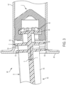
- the stopper 2 is shown in use with a plunger rod 40 and a syringe barrel 42 to form a syringe assembly 44.
- the stopper 2 and the plunger rod 40 are adapted for use with the syringe barrel 42.
- the syringe barrel 42 is made of medical-grade plastic or glass.
- the plunger rod 40 is made of a medical-grade plastic.
- the syringe barrel 42 is substantially cylindrical and extends from an open proximal end 46 to a distal dispensing end (not shown) from which fluid is ejected during use of the syringe assembly 44.
- the distal dispensing end includes an outlet opening and/or a mechanism (such as a luer fitting) for attachment to a separate medical device (such as a catheter).
- the open end 46 is configured to receive the stopper 2 and the plunger rod 40.
- a flange 48 is provided around the circumferential surface of the open end 46.
- At least one protrusion 50 projects inwardly from an inner surface 52 of the syringe barrel 42.
- the protrusion 50 extends around the entire circumferential surface of the inner surface 52 of the syringe barrel 42.
- the protrusion 50 is provided as a plurality of segments that extend around the circumferential surface of the inner surface 52.
- the protrusion 50 is provided adjacent the open end 46 of the syringe barrel 42. It is also contemplated that additional protrusions may be provided on the syringe barrel 42 at a distal position from the protrusion 50.
- the plunger rod 40 is operatively connected to the stopper 2, such that, upon depression of the plunger rod 40 in a distal direction, the stopper 2 is moved in a distal direction within the syringe barrel 42 to direct the fluid out of the dispensing end of the syringe barrel 42.
- the plunger rod 40 includes a main body portion 54, at least one support disk 56, 58, and an attachment member 60.
- the main body portion 54 includes a proximal end having an actuator button or tab (not shown) for moving the plunger rod 40 in a distal or proximal direction, and a distal end upon which the support disks 56, 58 are formed.
- the support disks 56, 58 extend outwardly from the distal end of the main body portion 54 and are substantially circular in shape to correspond to the shape of the syringe barrel 42. It is contemplated, however, that the support disks 56, 58 can have alternative shapes that are accommodated in the syringe barrel 42.
- the first support disk 56 is spaced proximally from the second support disk 58 on the distal end of the main body portion 54.
- the support disks 56, 58 have substantially the same diameter.
- the attachment member 60 of the plunger rod 40 is provided on the distal end of the plunger rod 40 and is spaced distally from the support disks 56, 58 on the plunger rod 40.
- the attachment member 60 has a smaller diameter than the support disks 56, 58.
- the attachment member 60 also includes at least one gripping protrusion 62 that extends distally from the attachment member 60.
- the gripping protrusions 62 are configured to assist in gripping the stopper 2 upon insertion of the attachment member 60 into the inner cavity 20 of the stopper 2.
- the plunger rod 40 is pushed in a distal direction into the open rearward end 6 of the stopper 2 so that the attachment member 60 is inserted into the inner cavity 20 of the stopper 2.
- the attachment member 60 As the plunger rod 40 is moved in the distal direction, the attachment member 60 is moved into the notch 24 defined in the inner contour 22 of the stopper 2. Using this interconnection between the attachment member 60 and the notch 24, the plunger rod 40 is retained in the stopper 2 such that the stopper 2 and plunger rod 40 move in conjunction with one another in the syringe barrel 42. It is also contemplated that the plunger rod 40 is molded integrally with the stopper 2 to form this arrangement. Since the diameter of the notch 24 is larger than the diameter of the attachment member 60, the plunger rod 40 is permitted to rotate relative to the stopper 2.
- the plunger rod 40 may become misaligned relative to a longitudinal axis A of the syringe assembly 44 that extends through the syringe barrel 42, the stopper 2, and the plunger rod 40. Misalignment of the plunger rod 40 can occur due to a clinician's thumb load misalignment on the plunger rod 40 with respect to the longitudinal axis A of the syringe assembly. Due to a side loading force B on the plunger rod 40, the plunger rod 40 may be rotated at an angle ⁇ relative to the longitudinal axis A of the syringe assembly 44.
- the attachment member 60 of the plunger rod 40 rotates within the stopper 2 causing stress concentrations in parts of the stopper 2. Due to these stress concentrations, the seal between the stopper 2 and the syringe barrel 42 may be deteriorated or the material of the stopper 2 may be worn down under high temperatures.
- the support disks 56, 58 are configured to bear against the protrusion 50 extending from the inner surface 52 of the syringe barrel 42.
- the proximal support disk 56 is configured to bear against a proximal side of the protrusion 50
- the distal support disk 58 is configured to bear against a distal side of the protrusion 50.
- the protrusion 50 acts as a bearing point for the support disks 56, 58 to limit the amount of rotation of the plunger rod 40 and to reduce the bearing force exerted by the attachment member 60 within the stopper 2.
- Using the protrusion 50 as a bearing point causes a significant portion of the side loading force B to be transferred directly from the plunger rod 40 to the syringe barrel 42 as a barrel reactive loading force C, which results in a reduced loading force that is transferred from the plunger rod 40 to the stopper 2.
- the reduced loading force on the side of the stopper 2 reduces asymmetric stopper deflection-induced loading/leakage in the seal between the stopper 2 and the syringe barrel 42.
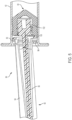
- FIG. 4 another aspect of the syringe assembly 64 is shown.
- the syringe barrel 42 is the same as that described in the syringe assembly 44 of FIG. 3 .
- the stopper 66 and the plunger rod 68 of this aspect are slightly different from the stopper 2 and the plunger rod 40 of the syringe assembly 44 shown in FIG. 3 .
- the stopper 66 has all of the same features as the stopper 2 of FIG. 3 , except the stopper 66 does not include a notch similar to the notch 24 in the stopper 2. Instead, the stopper 66 defines a plurality of notches 70 in an inner contour 72 of the stopper 66.
- the plunger rod 68 includes a main body portion 74, at least one support disk 76, 78, and an attachment member 80 configured to connect with the stopper 66.
- the attachment member 80 is provided on a distal end of the plunger rod 68 and is distally spaced from the support disks 76, 78.
- the attachment member 80 has a diameter smaller than the support disks 76, 78 and an inner cavity of the stopper 66.
- a plurality of protrusions 82 are provided on the circumferential outer surface of the attachment member 80 and are configured to connect the attachment member 80 within the stopper 66.
- the protrusions 82 are substantially triangular and correspond in shape to the notches 70 defined in the stopper 66.
- the attachment member 80 is inserted into the inner cavity of the stopper 66.
- the protrusions 82 are moved from a first notch 70 to a second notch 70 within the stopper 66.
- the notches 70 allow for distal movement of the attachment member 80 within the stopper 66, but prevent proximal movement of the attachment member 80 out of the stopper 66.
- a recess 84 is defined in the main body portion 74 of the plunger rod 68.
- the recess 84 is defined proximally from the first support disk 76.
- the recess 84 is formed between the first support disk 76 and a protrusion 86 that extends from the main body portion 74.
- the recess 84 assists in reducing the bearing load transferred to the stopper 66 upon misalignment of the plunger rod 68 within the syringe barrel 42.
- the plunger rod 92 includes at least one outer body member 94, an inner body member 96, at least one support disk 98, 100, and an attachment member 102 for connection of the plunger rod 92 to the stopper 66.
- a plurality of outer body member 94 surround the inner body member 96.
- the outer body members 94 are made of a rigid plastic material, and the inner body member 96 is made of a flexible plastic material.
- the inner body member 96 extends within the outer body member 94. Upon misalignment of the plunger rod 92 due to a side bearing load on the plunger rod 92, the inner body member 96 is configured to flex to reduce the angle of rotation ⁇ of the plunger rod 92 within the syringe barrel 42.
- the outer body members 94 remain rigid during rotation of the plunger rod 92.
- the attachment member 102 is formed on a distal end of the inner body member 96 so that, due to the flexion of the inner body member 96 during misalignment of the plunger rod 92, the amount of side bearing load transferred from the attachment member 102 to the stopper 66 is reduced.
- the inner body member 96 experiences significant deflection, while the outer body member 94 remains rigid.
Landscapes
- Health & Medical Sciences (AREA)
- Vascular Medicine (AREA)
- Engineering & Computer Science (AREA)
- Anesthesiology (AREA)
- Biomedical Technology (AREA)
- Heart & Thoracic Surgery (AREA)
- Hematology (AREA)
- Life Sciences & Earth Sciences (AREA)
- Animal Behavior & Ethology (AREA)
- General Health & Medical Sciences (AREA)
- Public Health (AREA)
- Veterinary Medicine (AREA)
- Infusion, Injection, And Reservoir Apparatuses (AREA)
Claims (14)
- Spritzenbaugruppe (44, 64, 90) mit:a) einem im Wesentlichen zylindrischen Spritzenzylinder (42) mit einem Fluidausgabeende, einem offenen Ende (46), und mindestens einem Vorsprung (50) neben dem offenen Ende (46), wobei der mindestens eine Vorsprung (50) von einer Innenfläche (52) des Spritzenzylinders (42) nach innen vorsteht;b) einem Stopfen (2, 66), der dazu ausgebildet ist, in dem offenen Ende (46) des Spritzenzylinders (42) aufgenommen zu werden; undc) einer Kolbenstange (40, 68, 92) mit einem Kolbenstangenkörper (54, 74, 94, 96), der sich von einem proximalen Ende entlang einer Längsachse (A) zu einem distalen Ende erstreckt, und mindestens einer Stützscheibe (56, 58, 76, 78, 98, 100), die an dem distalen Ende desselben angeordnet ist,wobei die mindestens eine Stützscheibe (56, 58, 76, 78, 98, 100) an der Kolbenstange (40, 68, 92) dazu ausgebildet ist, bei einer Fehlausrichtung der Kolbenstange (40, 68, 92) in dem Spritzenzylinder (42) gegen den Vorsprung (50) des Spritzenzylinders (42) anzuliegen,dadurch gekennzeichnet, dassdie mindestens eine Stützscheibe (56, 58, 76, 78, 98, 100) eine erste Stützscheibe (56, 76, 98) und eine zweite Stützscheibe (58, 78, 100) an der Kolbenstange (40, 68, 92) aufweist, die voneinander derart beabstandet sind, dass bei einer Fehlausrichtung der Kolbenstange (40, 68, 92) in dem Spritzenzylinder (42), die erste Stützscheibe (56, 76, 98) gegen eine proximale Seite des Vorsprungs (50) an einem ersten Lastaufnahmepunkt anliegt und die zweite Stützscheibe (58, 78, 100) gegen eine distale Seite des Vorsprungs (50) an einem zweiten Lastaufnahmepunkt anliegt.
- Spritzenbaugruppe (44, 64, 90) nach Anspruch 1, bei welcher der mindestens eine Vorsprung (50) des Spritzenzylinders (42) eine durchgehende Rippe ist, welche sich um eine Innenumfangsfläche des Spritzenzylinders (42) erstreckt.
- Spritzenbaugruppe (64) nach Anspruch 1, bei welcher die Kolbenstange (68) ferner eine Ausnehmung (84) aufweist, die in dem Kolbenstangenkörper (74) neben der ersten und der zweiten Stützscheibe (76, 78) ausgebildet ist, wobei die Ausnehmung (84) durch erste und zweite Vorsprungselemente (76, 86) definiert ist, die sich von einer Außenfläche des Kolbenstangenkörpers (74) erstrecken, wobei die erste Stützscheibe (76) das erste Vorsprungselement (86) aufweist, und
wobei bei einer Fehlausrichtung einer Kolbenstange (68) in dem Spritzenzylinder (42) das erste Vorsprungselement (86) gegen eine proximale Seite des Vorsprungs (50) an einem ersten Lastaufnahmepunkt anliegt, das zweite Vorsprungselement (76) gegen eine distale Seite des Vorsprungs an einem zweiten Lastaufnahmepunkt anliegt, und die zweite Stützscheibe (78) gegen die Innenseite des Spritzenzylinders an einem dritten Lastaufnahmepunkt anliegt. - Spritzenbaugruppe (44, 64, 90) nach Anspruch 1, bei welcher die Kolbenstange (40, 68, 92) ferner ein Befestigungselement (60, 80, 102) aufweist, das an dem distalen Ende vorgesehen ist und zur Verbindung mit dem Stopfen (2, 66) ausgebildet ist, und
wobei die erste Stützscheibe (56, 76, 98) und die zweite Stützscheibe (58, 78, 100) proximal von dem Befestigungselement (60, 80, 102) beabstandet sind. - Spritzenbaugruppe (90) nach Anspruch 1, bei welcher der Kolbenstangenkörper (94, 96) ferner ein starres äußeres Körperelement (94) und ein flexibles inneres Körperelement (96) aufweist, das in dem starren äußeren Körperelement (94) vorgesehen ist, wobei das flexible innere Körperelement (96) dazu ausgebildet ist, bei einer Fehlausrichtung der Kolbenstange (92) in dem Spritzenzylinder (42) auszulenken; und
wobei der Kolbenstangenkörper (94, 96) vorzugweise ein Befestigungselement (102) aufweist, das zur Verbindung mit dem Stopfen (66) ausgebildet ist, wobei das Befestigungselement (102) an einem distalen Ende des flexiblen inneren Körperelements vorgesehen ist. - Spritzenbaugruppe (44, 64, 90) nach Anspruch 1, bei welcher die Kolbenstange (68), vorgesehen zwischen der ersten und der zweiten Stützscheibe (76, 78), ferner einen flexiblen Bereich (88) aufweist, der dazu ausgebildet ist, bei einer Fehlausrichtung der Kolbenstange (92) in dem Spritzenzylinder (42) auszulenken.
- Spritzenbaugruppe (44, 64, 90) nach Anspruch 1, bei welcher der Stopfen (2, 66) einen Hauptkörperbereich (4) aufweist, der ein offenes hinteres Ende (6), ein geschlossenes vorderes Ende (8) und einen inneren Hohlraum (20) zum Aufnehmen des distalen Endes der Kolbenstange (40, 68, 92) definiert, und
wobei eine Innenfläche (22, 72) des inneren Hohlraums (20) eine Ausnehmung (24, 70) aufweist, die dazu ausgebildet ist, bei einer Fehlausrichtung der Kolbenstange in dem Spritzenzylinder als ein Lastaufnahmepunkt für die Kolbenstange zu wirken. - Spritzenbaugruppe (44, 64, 90) nach Anspruch 1, bei welcher der Stopfen (66) einen Hauptkörperbereich (4) aufweist, der ein offenes hinteres Ende, ein geschlossenes vorderes Ende (8) und einen inneren Hohlraum (20) zum Aufnehmen des distalen Endes der Kolbenstange (68, 92) definiert,wobei ein Bereich einer Innenfläche (72) des inneren Hohlraums (20) mehrere Kerben (70) definiert, die zum Aufnehmen mehrere Vorsprünge (82) ausgebildet sind, welche sich von dem distalen Ende des Kolbenstangenkörpers erstrecken, undwobei bei einer Fehlausrichtung der Kolbenstange (68, 92) in dem Spritzenzylinder (42) mindestens ein Vorsprung (82) an dem Kolbenstangenkörper gegen eine entsprechende erbe (70) im inneren Hohlraum (20) des Stopfens an einem Lastaufnahmepunkt anliegt.
- Spritzenbaugruppe (44, 64, 90) nach Anspruch 1, bei welcher der Stopfen (2, 66) aus einem thermoplastischen Elastomer hergestellt ist.
- Spritzenbaugruppe (44, 64, 90) nach Anspruch 1, bei welcher der Stopfen (2) aufweist:einen Hauptkörperbereich (4), der ein offenes hinteres Ende (6), ein geschlossenes vorderes Ende (8), und einen inneren Hohlraum (20), der zwischen dem hinteren Ende (6) und dem vorderen Ende (8) ausgebildet ist, wobei der innere Hohlraum (20) eine Innenkontur (22) mit einer Kerbe definiert, welche sich von einer Innenfläche des inneren Hohlraums nach außen erstreckt, wobei die Kerbe (24) eine erste Kontaktfläche (25a) der Innenkontur (22) von einer zweiten Kontaktfläche (25b) der Innenkontur (22) trennt;eine erste Rippe (34), die sich von einer Außenfläche des Hauptkörperbereichs (4) und um einen Außenumfang des Hauptkörperbereichs (4) erstreckt; undeine zweite Rippe (36), die von der ersten Rippe (34) beabstandet ist, wobei sich die zweite Rippe (36) von einer Außenfläche des Hauptkörperbereichs (4) und um einen Außenumfang des Hauptkörperbereichs (4) erstreckt,wobei eine Breite der ersten Kontaktfläche (25a) im Wesentlichen gleich einer Breite der ersten Rippe (34) ist, und eine Breite der zweiten Kontaktfläche (25b) im Wesentlichen gleich einer Breite der zweiten Rippe (36) ist.
- Spritzenanordnung (44, 64, 90) nach Anspruch 10, bei welcher die in der Innenkontur (22) gebildete Kerbe (24) eine verringerte Dicke des Hauptkörperbereichs (4) von der Innenkontur (22) zu einer Außenfläche des Hauptkörperbereichs (4) bereitstellt.
- Spritzenbaugruppe (44, 64, 90) nach Anspruch 10, bei welcher das geschlossene vordere Ende (8) des Hauptkörperbereichs (4) eine konische Form mit einer Spitze (14) aufweist.
- Spritzenbaugruppe (44, 64, 90) nach Anspruch 10, bei welcher eine Ausnehmung (38) in der Außenfläche des Hauptkörperbereichs zwischen der ersten Rippe (34) und der zweiten Rippe (36) gebildet ist, wobei eine Breite der Ausnehmung (38) im Wesentlichen gleich einer Breite der Kerbe (24) ist.
- Spritzenbaugruppe (44, 64, 90) nach Anspruch 10, bei welcher mindestens einen klappbaren Ausschnitt (30, 32) in der Innenkontur (22) des inneren Hohlraums (20) ausgebildet ist, wobei der klappbare Ausschnitt (30, 32) dem Stopfen (2) ermöglicht, unter Druck zusammenzuklappen oder zu biegen.
Applications Claiming Priority (2)
| Application Number | Priority Date | Filing Date | Title |
|---|---|---|---|
| US201862645353P | 2018-03-20 | 2018-03-20 | |
| PCT/US2019/022300 WO2019182870A1 (en) | 2018-03-20 | 2019-03-14 | Syringe stopper and plunger rod arrangement for a syringe assembly |
Publications (3)
| Publication Number | Publication Date |
|---|---|
| EP3768360A1 EP3768360A1 (de) | 2021-01-27 |
| EP3768360C0 EP3768360C0 (de) | 2025-07-09 |
| EP3768360B1 true EP3768360B1 (de) | 2025-07-09 |
Family
ID=65952155
Family Applications (1)
| Application Number | Title | Priority Date | Filing Date |
|---|---|---|---|
| EP19714005.6A Active EP3768360B1 (de) | 2018-03-20 | 2019-03-14 | Spritzenkolben und kolbenstangenanordnung für eine spritzenbaugruppe |
Country Status (6)
| Country | Link |
|---|---|
| US (1) | US11701472B2 (de) |
| EP (1) | EP3768360B1 (de) |
| JP (1) | JP7177166B2 (de) |
| CN (2) | CN116212164A (de) |
| CA (1) | CA3092690A1 (de) |
| WO (1) | WO2019182870A1 (de) |
Families Citing this family (3)
| Publication number | Priority date | Publication date | Assignee | Title |
|---|---|---|---|---|
| USD935608S1 (en) * | 2019-03-15 | 2021-11-09 | Chiesi Farmaceutici S.P.A. | Plunger for syringe |
| CN113840589A (zh) * | 2019-05-17 | 2021-12-24 | 西医药服务有限公司 | 用于治疗溶液的适应性初级包装 |
| US11933401B2 (en) * | 2020-10-09 | 2024-03-19 | Enplas Corporation | Plunger, instrument, and mold |
Citations (3)
| Publication number | Priority date | Publication date | Assignee | Title |
|---|---|---|---|---|
| GB960294A (en) * | 1962-06-12 | 1964-06-10 | Clark Holloway Hamilton | Syringe |
| KR20170036818A (ko) * | 2009-05-09 | 2017-04-03 | 백톤 디킨슨 앤드 컴퍼니 | 카테터 시스템을 퍼지하기 위한 장치 |
| EP3406284A1 (de) * | 2010-09-20 | 2018-11-28 | Becton, Dickinson and Company | Spritze mit deaktivierungsmechanismus |
Family Cites Families (21)
| Publication number | Priority date | Publication date | Assignee | Title |
|---|---|---|---|---|
| US2832340A (en) * | 1957-03-26 | 1958-04-29 | American Home Prod | Syringe push rod |
| GB2350317B (en) | 1996-07-15 | 2001-01-10 | Star Syringe Ltd | Apparatus for making syringes |
| EP1075293A1 (de) | 1998-04-30 | 2001-02-14 | Abbott Laboratories | Spritzenvorrichtung |
| US6171286B1 (en) * | 1999-04-20 | 2001-01-09 | James R. Gross | Self-aligning syringe plunger |
| MXPA05003837A (es) * | 2002-10-11 | 2005-06-22 | Becton Dickinson Co | Jeringa para un solo uso, con cubierta de seguridad. |
| EP1945284B1 (de) * | 2005-11-09 | 2019-12-18 | Hyprotek, Inc. | Spritzenvorrichtungen, bauteile von spritzenvorrichtungen und verfahren zur ausbildung von bauteilen und spritzenvorrichtungen |
| CN101743026B (zh) | 2007-06-04 | 2013-07-17 | 贝克顿·迪金森公司 | 预装填注射器用的正排出塞子 |
| DE102008042030A1 (de) * | 2008-09-12 | 2010-03-18 | Robert Bosch Gmbh | Kolben für eine Spritze |
| US9174007B2 (en) * | 2010-03-15 | 2015-11-03 | Becton, Dickinson And Company | Medical device including an air evacuation system |
| JP2010184140A (ja) | 2010-06-01 | 2010-08-26 | Terumo Corp | シリンジ |
| US9642970B2 (en) * | 2010-06-30 | 2017-05-09 | Retractable Technologies, Inc. | Syringe with retractable needle and moveable plunger seal |
| US20120271245A1 (en) * | 2011-04-21 | 2012-10-25 | Achan Jr Leonard | Malleable stopper for a syringe |
| US20130123712A1 (en) * | 2011-11-11 | 2013-05-16 | Becton, Dickinson And Company | Plunger Rod Retaining Anchors |
| WO2015031677A1 (en) * | 2013-08-30 | 2015-03-05 | Glucago Llc D/B/A Lyogo | Plunger and plunger valve for drug delivery |
| AU2014318264B2 (en) | 2013-09-16 | 2018-10-04 | Zoetis Services Llc | Assembly for sequentially delivering substances, and associated methods |
| MX383497B (es) * | 2013-10-28 | 2025-03-14 | Becton Dickinson Co | Tapon libre de fugas para un conjunto de jeringa que tiene fuerzas de sustentacion e inicial bajas. |
| AU2015315849B2 (en) * | 2014-09-10 | 2019-11-28 | Sio2 Medical Products, Llc | Three-position plungers, film coated plungers and related syringe assemblies |
| JP6827937B2 (ja) | 2015-09-17 | 2021-02-10 | テルモ株式会社 | シリンジ用プランジャおよびそれを用いたプレフィルドシリンジ |
| US10369292B2 (en) | 2016-01-15 | 2019-08-06 | W. L. Gore & Associates, Inc. | Syringe plunger assemblies |
| CN105771036A (zh) * | 2016-03-29 | 2016-07-20 | 陆盘中 | 一次性锁定安全自毁式注射器 |
| EP3254717A1 (de) * | 2016-06-09 | 2017-12-13 | Novartis Ag | Spritze und verfahren zur ausgabe einer flüssigkeit |
-
2019
- 2019-03-14 US US16/977,904 patent/US11701472B2/en active Active
- 2019-03-14 EP EP19714005.6A patent/EP3768360B1/de active Active
- 2019-03-14 CN CN202310410238.0A patent/CN116212164A/zh active Pending
- 2019-03-14 CA CA3092690A patent/CA3092690A1/en active Pending
- 2019-03-14 JP JP2020546503A patent/JP7177166B2/ja active Active
- 2019-03-14 WO PCT/US2019/022300 patent/WO2019182870A1/en not_active Ceased
- 2019-03-14 CN CN201980020147.8A patent/CN111867661B/zh active Active
Patent Citations (3)
| Publication number | Priority date | Publication date | Assignee | Title |
|---|---|---|---|---|
| GB960294A (en) * | 1962-06-12 | 1964-06-10 | Clark Holloway Hamilton | Syringe |
| KR20170036818A (ko) * | 2009-05-09 | 2017-04-03 | 백톤 디킨슨 앤드 컴퍼니 | 카테터 시스템을 퍼지하기 위한 장치 |
| EP3406284A1 (de) * | 2010-09-20 | 2018-11-28 | Becton, Dickinson and Company | Spritze mit deaktivierungsmechanismus |
Also Published As
| Publication number | Publication date |
|---|---|
| CN111867661B (zh) | 2023-04-21 |
| CA3092690A1 (en) | 2019-09-26 |
| JP7177166B2 (ja) | 2022-11-22 |
| EP3768360C0 (de) | 2025-07-09 |
| JP2021516568A (ja) | 2021-07-08 |
| WO2019182870A1 (en) | 2019-09-26 |
| CN111867661A (zh) | 2020-10-30 |
| EP3768360A1 (de) | 2021-01-27 |
| CN116212164A (zh) | 2023-06-06 |
| US11701472B2 (en) | 2023-07-18 |
| US20210038823A1 (en) | 2021-02-11 |
Similar Documents
| Publication | Publication Date | Title |
|---|---|---|
| JP6283056B2 (ja) | プラスチックストッパ | |
| EP3768360B1 (de) | Spritzenkolben und kolbenstangenanordnung für eine spritzenbaugruppe | |
| US10307547B2 (en) | Thumb press frangible feature for re-use prevention | |
| EP3334483B1 (de) | Stopfen für einen medikamentenbehälter | |
| US20110077601A1 (en) | Quadraglide Syringe | |
| CN121038833A (zh) | 用于注射器端头的两件式密封帽 | |
| JP2016179117A (ja) | プレフィルドシリンジ | |
| WO2024028440A1 (en) | Tip cap assembly for an injection system | |
| JP2017093964A (ja) | プレフィルドシリンジ用ガスケット |
Legal Events
| Date | Code | Title | Description |
|---|---|---|---|
| STAA | Information on the status of an ep patent application or granted ep patent |
Free format text: STATUS: UNKNOWN |
|
| STAA | Information on the status of an ep patent application or granted ep patent |
Free format text: STATUS: THE INTERNATIONAL PUBLICATION HAS BEEN MADE |
|
| PUAI | Public reference made under article 153(3) epc to a published international application that has entered the european phase |
Free format text: ORIGINAL CODE: 0009012 |
|
| STAA | Information on the status of an ep patent application or granted ep patent |
Free format text: STATUS: REQUEST FOR EXAMINATION WAS MADE |
|
| 17P | Request for examination filed |
Effective date: 20200901 |
|
| AK | Designated contracting states |
Kind code of ref document: A1 Designated state(s): AL AT BE BG CH CY CZ DE DK EE ES FI FR GB GR HR HU IE IS IT LI LT LU LV MC MK MT NL NO PL PT RO RS SE SI SK SM TR |
|
| AX | Request for extension of the european patent |
Extension state: BA ME |
|
| DAV | Request for validation of the european patent (deleted) | ||
| DAX | Request for extension of the european patent (deleted) | ||
| STAA | Information on the status of an ep patent application or granted ep patent |
Free format text: STATUS: EXAMINATION IS IN PROGRESS |
|
| 17Q | First examination report despatched |
Effective date: 20230117 |
|
| GRAP | Despatch of communication of intention to grant a patent |
Free format text: ORIGINAL CODE: EPIDOSNIGR1 |
|
| STAA | Information on the status of an ep patent application or granted ep patent |
Free format text: STATUS: GRANT OF PATENT IS INTENDED |
|
| INTG | Intention to grant announced |
Effective date: 20250211 |
|
| GRAS | Grant fee paid |
Free format text: ORIGINAL CODE: EPIDOSNIGR3 |
|
| GRAA | (expected) grant |
Free format text: ORIGINAL CODE: 0009210 |
|
| STAA | Information on the status of an ep patent application or granted ep patent |
Free format text: STATUS: THE PATENT HAS BEEN GRANTED |
|
| AK | Designated contracting states |
Kind code of ref document: B1 Designated state(s): AL AT BE BG CH CY CZ DE DK EE ES FI FR GB GR HR HU IE IS IT LI LT LU LV MC MK MT NL NO PL PT RO RS SE SI SK SM TR |
|
| REG | Reference to a national code |
Ref country code: GB Ref legal event code: FG4D |
|
| REG | Reference to a national code |
Ref country code: CH Ref legal event code: EP |
|
| REG | Reference to a national code |
Ref country code: IE Ref legal event code: FG4D |
|
| REG | Reference to a national code |
Ref country code: DE Ref legal event code: R096 Ref document number: 602019072262 Country of ref document: DE |
|
| U01 | Request for unitary effect filed |
Effective date: 20250811 |
|
| U07 | Unitary effect registered |
Designated state(s): AT BE BG DE DK EE FI FR IT LT LU LV MT NL PT RO SE SI Effective date: 20250820 |
|
| PG25 | Lapsed in a contracting state [announced via postgrant information from national office to epo] |
Ref country code: IS Free format text: LAPSE BECAUSE OF FAILURE TO SUBMIT A TRANSLATION OF THE DESCRIPTION OR TO PAY THE FEE WITHIN THE PRESCRIBED TIME-LIMIT Effective date: 20251109 |
|
| PG25 | Lapsed in a contracting state [announced via postgrant information from national office to epo] |
Ref country code: NO Free format text: LAPSE BECAUSE OF FAILURE TO SUBMIT A TRANSLATION OF THE DESCRIPTION OR TO PAY THE FEE WITHIN THE PRESCRIBED TIME-LIMIT Effective date: 20251009 |
|
| PG25 | Lapsed in a contracting state [announced via postgrant information from national office to epo] |
Ref country code: HR Free format text: LAPSE BECAUSE OF FAILURE TO SUBMIT A TRANSLATION OF THE DESCRIPTION OR TO PAY THE FEE WITHIN THE PRESCRIBED TIME-LIMIT Effective date: 20250709 |
|
| PG25 | Lapsed in a contracting state [announced via postgrant information from national office to epo] |
Ref country code: GR Free format text: LAPSE BECAUSE OF FAILURE TO SUBMIT A TRANSLATION OF THE DESCRIPTION OR TO PAY THE FEE WITHIN THE PRESCRIBED TIME-LIMIT Effective date: 20251010 |
|
| PG25 | Lapsed in a contracting state [announced via postgrant information from national office to epo] |
Ref country code: PL Free format text: LAPSE BECAUSE OF FAILURE TO SUBMIT A TRANSLATION OF THE DESCRIPTION OR TO PAY THE FEE WITHIN THE PRESCRIBED TIME-LIMIT Effective date: 20250709 |
|
| PG25 | Lapsed in a contracting state [announced via postgrant information from national office to epo] |
Ref country code: RS Free format text: LAPSE BECAUSE OF FAILURE TO SUBMIT A TRANSLATION OF THE DESCRIPTION OR TO PAY THE FEE WITHIN THE PRESCRIBED TIME-LIMIT Effective date: 20251009 |
|
| PG25 | Lapsed in a contracting state [announced via postgrant information from national office to epo] |
Ref country code: ES Free format text: LAPSE BECAUSE OF FAILURE TO SUBMIT A TRANSLATION OF THE DESCRIPTION OR TO PAY THE FEE WITHIN THE PRESCRIBED TIME-LIMIT Effective date: 20250709 |