EP3768071B1 - Système de transport de tours de croissance verticales pour agriculture à environnement contrôlé - Google Patents
Système de transport de tours de croissance verticales pour agriculture à environnement contrôlé Download PDFInfo
- Publication number
- EP3768071B1 EP3768071B1 EP19715343.0A EP19715343A EP3768071B1 EP 3768071 B1 EP3768071 B1 EP 3768071B1 EP 19715343 A EP19715343 A EP 19715343A EP 3768071 B1 EP3768071 B1 EP 3768071B1
- Authority
- EP
- European Patent Office
- Prior art keywords
- grow
- tower
- towers
- line
- production system
- Prior art date
- Legal status (The legal status is an assumption and is not a legal conclusion. Google has not performed a legal analysis and makes no representation as to the accuracy of the status listed.)
- Active
Links
- 230000007246 mechanism Effects 0.000 claims description 43
- 238000012272 crop production Methods 0.000 claims 9
- 230000012010 growth Effects 0.000 description 23
- 241000196324 Embryophyta Species 0.000 description 22
- 235000015097 nutrients Nutrition 0.000 description 22
- 238000012545 processing Methods 0.000 description 16
- 238000003973 irrigation Methods 0.000 description 14
- 230000002262 irrigation Effects 0.000 description 14
- 239000000243 solution Substances 0.000 description 14
- 230000033001 locomotion Effects 0.000 description 11
- 238000003306 harvesting Methods 0.000 description 10
- 238000004519 manufacturing process Methods 0.000 description 9
- 238000012546 transfer Methods 0.000 description 8
- 238000001125 extrusion Methods 0.000 description 6
- 239000012530 fluid Substances 0.000 description 6
- 239000000463 material Substances 0.000 description 5
- 238000004140 cleaning Methods 0.000 description 4
- 238000005516 engineering process Methods 0.000 description 4
- 238000009313 farming Methods 0.000 description 4
- 230000008878 coupling Effects 0.000 description 3
- 238000010168 coupling process Methods 0.000 description 3
- 238000005859 coupling reaction Methods 0.000 description 3
- 238000013461 design Methods 0.000 description 3
- 238000009826 distribution Methods 0.000 description 3
- 239000002609 medium Substances 0.000 description 3
- 238000000034 method Methods 0.000 description 3
- 235000016709 nutrition Nutrition 0.000 description 3
- 238000005406 washing Methods 0.000 description 3
- XLYOFNOQVPJJNP-UHFFFAOYSA-N water Substances O XLYOFNOQVPJJNP-UHFFFAOYSA-N 0.000 description 3
- CURLTUGMZLYLDI-UHFFFAOYSA-N Carbon dioxide Chemical compound O=C=O CURLTUGMZLYLDI-UHFFFAOYSA-N 0.000 description 2
- 229910001335 Galvanized steel Inorganic materials 0.000 description 2
- 125000002777 acetyl group Chemical group [H]C([H])([H])C(*)=O 0.000 description 2
- 239000004676 acrylonitrile butadiene styrene Substances 0.000 description 2
- 238000010586 diagram Methods 0.000 description 2
- 230000000694 effects Effects 0.000 description 2
- 230000007613 environmental effect Effects 0.000 description 2
- 235000013305 food Nutrition 0.000 description 2
- 239000008397 galvanized steel Substances 0.000 description 2
- 229910052751 metal Inorganic materials 0.000 description 2
- 239000002184 metal Substances 0.000 description 2
- 238000012986 modification Methods 0.000 description 2
- 230000004048 modification Effects 0.000 description 2
- 239000002991 molded plastic Substances 0.000 description 2
- 238000005457 optimization Methods 0.000 description 2
- 230000008635 plant growth Effects 0.000 description 2
- 239000004800 polyvinyl chloride Substances 0.000 description 2
- 239000000725 suspension Substances 0.000 description 2
- 238000013519 translation Methods 0.000 description 2
- 229910000906 Bronze Inorganic materials 0.000 description 1
- 229920004943 Delrin® Polymers 0.000 description 1
- 239000004699 Ultra-high molecular weight polyethylene Substances 0.000 description 1
- DHKHKXVYLBGOIT-UHFFFAOYSA-N acetaldehyde Diethyl Acetal Natural products CCOC(C)OCC DHKHKXVYLBGOIT-UHFFFAOYSA-N 0.000 description 1
- XECAHXYUAAWDEL-UHFFFAOYSA-N acrylonitrile butadiene styrene Chemical compound C=CC=C.C=CC#N.C=CC1=CC=CC=C1 XECAHXYUAAWDEL-UHFFFAOYSA-N 0.000 description 1
- 229920000122 acrylonitrile butadiene styrene Polymers 0.000 description 1
- 229910052782 aluminium Inorganic materials 0.000 description 1
- XAGFODPZIPBFFR-UHFFFAOYSA-N aluminium Chemical compound [Al] XAGFODPZIPBFFR-UHFFFAOYSA-N 0.000 description 1
- 230000003698 anagen phase Effects 0.000 description 1
- 238000013459 approach Methods 0.000 description 1
- 239000010974 bronze Substances 0.000 description 1
- 229910002092 carbon dioxide Inorganic materials 0.000 description 1
- 239000001569 carbon dioxide Substances 0.000 description 1
- 230000008859 change Effects 0.000 description 1
- 238000010276 construction Methods 0.000 description 1
- 230000001276 controlling effect Effects 0.000 description 1
- KUNSUQLRTQLHQQ-UHFFFAOYSA-N copper tin Chemical compound [Cu].[Sn] KUNSUQLRTQLHQQ-UHFFFAOYSA-N 0.000 description 1
- 238000005260 corrosion Methods 0.000 description 1
- 230000007797 corrosion Effects 0.000 description 1
- 244000038559 crop plants Species 0.000 description 1
- 238000012258 culturing Methods 0.000 description 1
- 235000013399 edible fruits Nutrition 0.000 description 1
- 239000012636 effector Substances 0.000 description 1
- 230000002349 favourable effect Effects 0.000 description 1
- 230000000238 gravitropic effect Effects 0.000 description 1
- 230000005484 gravity Effects 0.000 description 1
- 235000021384 green leafy vegetables Nutrition 0.000 description 1
- 239000001963 growth medium Substances 0.000 description 1
- 229920001519 homopolymer Polymers 0.000 description 1
- 239000003501 hydroponics Substances 0.000 description 1
- 238000002347 injection Methods 0.000 description 1
- 239000007924 injection Substances 0.000 description 1
- 238000001746 injection moulding Methods 0.000 description 1
- 238000003780 insertion Methods 0.000 description 1
- 230000037431 insertion Effects 0.000 description 1
- 239000007788 liquid Substances 0.000 description 1
- 238000010801 machine learning Methods 0.000 description 1
- 238000012423 maintenance Methods 0.000 description 1
- 235000021049 nutrient content Nutrition 0.000 description 1
- 230000035764 nutrition Effects 0.000 description 1
- 238000004806 packaging method and process Methods 0.000 description 1
- 239000004033 plastic Substances 0.000 description 1
- 229920003023 plastic Polymers 0.000 description 1
- 229920000915 polyvinyl chloride Polymers 0.000 description 1
- 238000004382 potting Methods 0.000 description 1
- 238000002360 preparation method Methods 0.000 description 1
- 230000008569 process Effects 0.000 description 1
- 238000003908 quality control method Methods 0.000 description 1
- 238000004064 recycling Methods 0.000 description 1
- 230000001105 regulatory effect Effects 0.000 description 1
- 238000005096 rolling process Methods 0.000 description 1
- 239000002904 solvent Substances 0.000 description 1
- 238000003860 storage Methods 0.000 description 1
- 230000032258 transport Effects 0.000 description 1
- 229920000785 ultra high molecular weight polyethylene Polymers 0.000 description 1
- 235000013311 vegetables Nutrition 0.000 description 1
- 230000017260 vegetative to reproductive phase transition of meristem Effects 0.000 description 1
- 230000000007 visual effect Effects 0.000 description 1
Images


Classifications
-
- A—HUMAN NECESSITIES
- A01—AGRICULTURE; FORESTRY; ANIMAL HUSBANDRY; HUNTING; TRAPPING; FISHING
- A01G—HORTICULTURE; CULTIVATION OF VEGETABLES, FLOWERS, RICE, FRUIT, VINES, HOPS OR SEAWEED; FORESTRY; WATERING
- A01G9/00—Cultivation in receptacles, forcing-frames or greenhouses; Edging for beds, lawn or the like
- A01G9/02—Receptacles, e.g. flower-pots or boxes; Glasses for cultivating flowers
- A01G9/029—Receptacles for seedlings
- A01G9/0299—Handling or transporting of soil blocks or seedlings
-
- A—HUMAN NECESSITIES
- A01—AGRICULTURE; FORESTRY; ANIMAL HUSBANDRY; HUNTING; TRAPPING; FISHING
- A01G—HORTICULTURE; CULTIVATION OF VEGETABLES, FLOWERS, RICE, FRUIT, VINES, HOPS OR SEAWEED; FORESTRY; WATERING
- A01G31/00—Soilless cultivation, e.g. hydroponics
- A01G31/02—Special apparatus therefor
- A01G31/04—Hydroponic culture on conveyors
- A01G31/045—Hydroponic culture on conveyors with containers guided along a rail
-
- A—HUMAN NECESSITIES
- A01—AGRICULTURE; FORESTRY; ANIMAL HUSBANDRY; HUNTING; TRAPPING; FISHING
- A01G—HORTICULTURE; CULTIVATION OF VEGETABLES, FLOWERS, RICE, FRUIT, VINES, HOPS OR SEAWEED; FORESTRY; WATERING
- A01G27/00—Self-acting watering devices, e.g. for flower-pots
- A01G27/005—Reservoirs connected to flower-pots through conduits
-
- A—HUMAN NECESSITIES
- A01—AGRICULTURE; FORESTRY; ANIMAL HUSBANDRY; HUNTING; TRAPPING; FISHING
- A01G—HORTICULTURE; CULTIVATION OF VEGETABLES, FLOWERS, RICE, FRUIT, VINES, HOPS OR SEAWEED; FORESTRY; WATERING
- A01G31/00—Soilless cultivation, e.g. hydroponics
- A01G31/02—Special apparatus therefor
- A01G31/04—Hydroponic culture on conveyors
-
- A—HUMAN NECESSITIES
- A01—AGRICULTURE; FORESTRY; ANIMAL HUSBANDRY; HUNTING; TRAPPING; FISHING
- A01G—HORTICULTURE; CULTIVATION OF VEGETABLES, FLOWERS, RICE, FRUIT, VINES, HOPS OR SEAWEED; FORESTRY; WATERING
- A01G31/00—Soilless cultivation, e.g. hydroponics
- A01G31/02—Special apparatus therefor
- A01G31/06—Hydroponic culture on racks or in stacked containers
-
- A—HUMAN NECESSITIES
- A01—AGRICULTURE; FORESTRY; ANIMAL HUSBANDRY; HUNTING; TRAPPING; FISHING
- A01G—HORTICULTURE; CULTIVATION OF VEGETABLES, FLOWERS, RICE, FRUIT, VINES, HOPS OR SEAWEED; FORESTRY; WATERING
- A01G9/00—Cultivation in receptacles, forcing-frames or greenhouses; Edging for beds, lawn or the like
- A01G9/02—Receptacles, e.g. flower-pots or boxes; Glasses for cultivating flowers
- A01G9/022—Pots for vertical horticulture
- A01G9/023—Multi-tiered planters
-
- B—PERFORMING OPERATIONS; TRANSPORTING
- B65—CONVEYING; PACKING; STORING; HANDLING THIN OR FILAMENTARY MATERIAL
- B65G—TRANSPORT OR STORAGE DEVICES, e.g. CONVEYORS FOR LOADING OR TIPPING, SHOP CONVEYOR SYSTEMS OR PNEUMATIC TUBE CONVEYORS
- B65G25/00—Conveyors comprising a cyclically-moving, e.g. reciprocating, carrier or impeller which is disengaged from the load during the return part of its movement
- B65G25/04—Conveyors comprising a cyclically-moving, e.g. reciprocating, carrier or impeller which is disengaged from the load during the return part of its movement the carrier or impeller having identical forward and return paths of movement, e.g. reciprocating conveyors
- B65G25/08—Conveyors comprising a cyclically-moving, e.g. reciprocating, carrier or impeller which is disengaged from the load during the return part of its movement the carrier or impeller having identical forward and return paths of movement, e.g. reciprocating conveyors having impellers, e.g. pushers
- B65G25/10—Conveyors comprising a cyclically-moving, e.g. reciprocating, carrier or impeller which is disengaged from the load during the return part of its movement the carrier or impeller having identical forward and return paths of movement, e.g. reciprocating conveyors having impellers, e.g. pushers with impeller pivotally mounted on a reciprocating bar
-
- B—PERFORMING OPERATIONS; TRANSPORTING
- B65—CONVEYING; PACKING; STORING; HANDLING THIN OR FILAMENTARY MATERIAL
- B65G—TRANSPORT OR STORAGE DEVICES, e.g. CONVEYORS FOR LOADING OR TIPPING, SHOP CONVEYOR SYSTEMS OR PNEUMATIC TUBE CONVEYORS
- B65G2201/00—Indexing codes relating to handling devices, e.g. conveyors, characterised by the type of product or load being conveyed or handled
- B65G2201/02—Articles
-
- Y—GENERAL TAGGING OF NEW TECHNOLOGICAL DEVELOPMENTS; GENERAL TAGGING OF CROSS-SECTIONAL TECHNOLOGIES SPANNING OVER SEVERAL SECTIONS OF THE IPC; TECHNICAL SUBJECTS COVERED BY FORMER USPC CROSS-REFERENCE ART COLLECTIONS [XRACs] AND DIGESTS
- Y02—TECHNOLOGIES OR APPLICATIONS FOR MITIGATION OR ADAPTATION AGAINST CLIMATE CHANGE
- Y02P—CLIMATE CHANGE MITIGATION TECHNOLOGIES IN THE PRODUCTION OR PROCESSING OF GOODS
- Y02P60/00—Technologies relating to agriculture, livestock or agroalimentary industries
- Y02P60/20—Reduction of greenhouse gas [GHG] emissions in agriculture, e.g. CO2
- Y02P60/21—Dinitrogen oxide [N2O], e.g. using aquaponics, hydroponics or efficiency measures
Definitions
- the disclosure relates generally to controlled environment agriculture and, more particularly, to conveyance and irrigation systems for vertical plant production systems.
- US Patent Publication Nos. 2018/0014485 and 2018/0014486 both assigned to the assignee of the present disclosure, describe environmentally controlled vertical farming systems.
- the vertical farming structure e.g., a vertical column
- the vertical farming structure may be moved about an automated conveyance system in an open or closed-loop fashion, exposed to precision-controlled lighting, airflow and humidity, with ideal nutritional support.
- US Patent Pub. No. US 2017/0055460 (“Brusatore”) describes a system for continuous automated growing of plants.
- a vertical array of plant supporting arms extends radially from a central axis.
- Each arm includes pot receptacles which receive the plant seedling, and liquid nutrients and water.
- the potting arms are rotated beneath grow lamps and pollinating arms. However, the spacing between plants appears to be fixed.
- WO 2017/217130 describes a hydroponic system comprising a plurality of seedbeds, a suspension section, and a conveyance mechanism.
- the suspension section suspends the seedbeds in a state in which the plurality of seedbeds are arrayed in a horizontal direction from a seedling planting side to a harvesting side.
- the conveyance mechanism conveys the plurality of seedbeds in a horizontal direction while widening the gaps between the seedbeds in the horizontal direction in a stepwise or continuous manner.
- JP H0614663 describes equipment for moving plant bodies, in which plural columns supporting culturing plants are movably supported by a support frame leaving a space in the direction of movement.
- a conveying mechanism set under a plant-supporting unit is equipped with a mobile frame, a drive frame, a coupling mechanism for coupling both the frames and a drive mechanism allowing the drive frame to perform a reciprocating motion in the direction of movement.
- the coupling mechanism occupies the holding position where the columns are held by the mobile frame and moved in the same direction only in a forward movement operation of the mobile frame while the mobile frame performs a reciprocating motion corresponding to a reciprocating motion of the drive frame.
- EP 0610137 describes a unit for plant culture comprising mobile modules suspended vertically so as to form lines of modules which receive the plants. The modules are driven with a rotary movement about their vertical axis and with a translation movement which makes it possible to displace the modules horizontally.
- the present disclosure is directed to a vertical farming structure having vertical grow towers and associated conveyance mechanisms for moving the vertical grow towers through a controlled environment, while being exposed to controlled conditions, such as lighting, airflow, humidity and nutritional support.
- the present disclosure describes a reciprocating cam mechanism that provides a cost-efficient mechanism for conveying vertical grow towers in the controlled environment.
- the reciprocating cam mechanism can be arranged to increase the spacing of the grow towers as they are conveyed through the controlled environment to index the crops growing on the towers.
- the present disclosure also describes an irrigation system that provides aqueous nutrient solution to the vertical grow towers.
- Figures 1 and 2 illustrate a controlled environment agriculture system 10 according to one possible embodiment of the invention.
- the system 10 may include an environmentally-controlled growing chamber 20, a vertical tower conveyance system 200 disposed within the growing chamber 20 and configured to convey grow towers 50 with crops disposed therein, and a central processing facility 30.
- the crops or plants species that may be grown may be gravitropic/geotropic and/or phototropic, or some combination thereof.
- the crops or plant species may vary considerably and include various leaf vegetables, fruiting vegetables, flowering crops, fruits and the like.
- the controlled environment agriculture system 10 may be configured to grow a single crop type at a time or to grow multiple crop types concurrently.
- the system 10 may also include conveyance systems for moving the grow towers in a circuit throughout the crop's growth cycle, the circuit comprising a staging area configured for loading the grow towers into and out of the vertical tower conveyance mechanism 200.
- the central processing system 30 may include one or more conveyance mechanisms for directing grow towers to stations in the central processing system 30-e.g., stations for loading plants into, and harvesting crops from, the grow towers.
- the vertical tower conveyance system 200 within the growing chamber 20, is configured to support and translate one or more grow towers 50 along grow lines 202. Each grow tower 50 is configured for containing plant growth media that supports a root structure of at least one crop plant growing therein.
- Each grow tower 50 is also configured to releasably attach to a grow line 202 in a vertical orientation and move along the grow line 202 during a growth phase.
- the vertical tower conveyance mechanism 200 and the central processing system 30 can be arranged in a production circuit under control of one or more computing systems.
- the growth environment 20 may include light emitting sources positioned at various locations between and along the grow lines 202 of the vertical tower conveyance system 200.
- the light emitting sources can be positioned laterally relative to the grow towers 50 in the grow line 202 and configured to emit light toward the lateral faces of the grow towers 50 that include openings from which crops grow.
- the light emitting sources may be incorporated into a water-cooled, LED lighting system as described in U.S. Publ. No. 2017/01 46226A1 .
- the LED lights may be arranged in a bar-like structure.
- the bar-like structure may be placed in a vertical orientation to emit light laterally to substantially the entire length of adjacent grow towers 50.
- Multiple light bar structures may be arranged in the growth environment 20 along and between the grow lines 202. Other lighting systems and configurations may be employed.
- the light bars may be arranged horizontally between grow lines 202.
- the growth environment 20 may also include a nutrient supply system configured to supply an aqueous crop nutrient solution to the crops as they translate through the growth chamber 20.
- the nutrient supply system may apply aqueous crop nutrient solution to the top of the grow towers 50. Gravity may cause the solution travel down the vertically-oriented grow tower 50 and through the length thereof to supply solution to the crops disposed along the length of the grow tower 50.
- the growth environment 20 may also include an airflow source configured to, when a tower is mounted to a grow line 202, direct airflow in the lateral growth direction of growth and through an under-canopy of the growing plant, so as to disturb the boundary layer of the under-canopy of the growing plant.
- airflow may come from the top of the canopy or orthogonal to the direction of plant growth.
- the growth environment 20 may also include a control system, and associated sensors, for regulating at least one growing condition, such as air temperature, airflow speed, relative air humidity, and ambient carbon dioxide gas content.
- the control system may for example include such sub-systems as HVAC units, chillers, fans and associated ducting and air handling equipment.
- Grow towers 50 may have identifying attributes (such as bar codes or RFID tags).
- the controlled environment agriculture system 10 may include corresponding sensors and programming logic for tracking the grow towers 50 during various stages of the farm production cycle and/or for controlling one or more conditions of the growth environment.
- the operation of control system and the length of time towers remain in growth environment can vary considerably depending on a variety of factors, such as crop type and other factors.
- grow towers 50 with newly transplanted crops or seedlings are transferred from the central processing system 30 into the vertical tower conveyance system 200.
- Vertical tower conveyance system 200 moves the grow towers 50 along respective grow lines 202 in growth environment 20 in a controlled fashion, as discussed in more detail below.
- Crops disposed in grow towers 50 are exposed to the controlled conditions of growth environment (e.g., light, temperature, humidity, air flow, aqueous nutrient supply, etc.).
- the control system is capable of automated adjustments to optimize growing conditions within the growth chamber 20 to make continuous improvements to various attributes, such as crop yields, visual appeal and nutrient content.
- US Patent Publication Nos US Patent Publication Nos.
- 2018/0014485 and 2018/0014486 describe application of machine learning and other operations to optimize grow conditions in a vertical farming system.
- environmental condition sensors may be disposed on grow towers 50 or at various locations in growth environment 20. When crops are ready for harvesting, grow towers 50 with crops to be harvested are transferred from the vertical tower conveyance system 200 to the central processing system 30 for harvesting and other processing operations.
- Central processing system 30 may include processing stations directed to injecting seedlings into towers 50, harvesting crops from towers 50, and cleaning towers 50 that have been harvested. Central processing system 30 may also include conveyance mechanisms that move towers 50 between such processing stations. For example, as Figure 1 illustrates, central processing system 30 may include harvester station 32, washing station 34, and transplanter station 36. Harvester station 32 may deposit harvested crops into food-safe containers and may include a conveyance mechanism for conveying the containers to post-harvesting facilities (e.g., preparation, washing, packaging and storage) that are beyond the scope of this disclosure.
- post-harvesting facilities e.g., preparation, washing, packaging and storage
- Controlled environment agriculture system 10 may also include one or more conveyance mechanisms for transferring grow towers 50 between growth environment 20 and central processing system 30.
- the stations of central processing system 30 operate on grow towers 50 in a horizontal orientation.
- an automated pickup station 43, and associated control logic may be operative to releasably grasp a horizontal tower from a loading location, rotate the tower to a vertical orientation and attach the tower to a transfer station for insertion into a selected grow line 202 of the growth environment 20.
- automated laydown station 41 may be operative to releasably grasp and move a vertically-oriented grow tower 50 from a buffer location, rotate the grow tower 50 to a horizontal orientation and place it on a conveyance system for loading into harvester station 32.
- the conveyance system may bypass the harvester station 32 and carry the grow tower to washing station 34 (or some other station).
- the automated laydown and pickup stations 41 and 43 may each comprise a six-degrees of freedom robotic arm, such as a FANUC robot.
- the stations 41 and 43 may also include end effectors for releasably grasping grow towers 50 at opposing ends.
- Growth environment 20 may also include automated loading and unloading mechanisms for inserting grow towers 50 into selected grow lines 202 and unloading grow towers 50 from the grow lines 202.
- the load transfer conveyance mechanism 47 may include a powered and free conveyor system that conveys carriages each loaded with a grow tower 50 from the automated pickup station 43 to a selected grow line 202.
- Vertical grow tower conveyance system 200 may include sensors (such as RFID or bar code sensors) to identify a given grow tower 50 and, under control logic, select a grow line 202 for the grow tower 50. Particular algorithms for grow line selection can vary considerably depending on a number of factors and is beyond the scope of this disclosure.
- the load transfer conveyance mechanism 47 may also include one or more linear actuators that pushes the grow tower 50 onto a grow line 202.
- the unload transfer conveyance mechanism 45 may include one or more linear actuators that push or pull grow towers from a grow line 202 onto a carriage of another powered and free conveyor mechanism, which conveys the carriages 1202 from the grow line 202 to the automated laydown station 41.
- Figure 12 illustrates a carriage 1202 that may be used in a powered and free conveyor mechanism
- carriage 1202 includes hook 1204 that engages hook 52 attached to a grow tower 50.
- a latch assembly 1206 may secure the grow tower 50 while it is being conveyed to and from various locations in the system.
- one or both of load transfer conveyance mechanism 47 and unload transfer conveyance mechanism 45 may be configured with a sufficient track distance to establish a zone where grow towers 50 may be buffered.
- unload transfer conveyance mechanism 45 may be controlled such that it unloads a set of towers 50 to be harvested unto carriages 1202 that are moved to a buffer region of the track.
- automated pickup station 43 may load a set of towers to be inserted into growth environment 20 onto carriages 1202 disposed in a buffer region of the track associated with load transfer conveyance mechanism 47.
- Grow towers 50 provide the sites for individual crops to grow in the system.
- a hook 52 attaches to the top of grow tower 50.
- Hook 52 allows grow tower 50 to be supported by a grow line 202 when it is inserted into the vertical tower conveyance system 200.
- a grow tower 50 measures 5.172 meters long, where the extruded length of the tower is 5.0 meters, and the hook is 0.172 meters long.
- the extruded rectangular profile of the grow tower 50 measures 57mm x 93mm (2.25" x 3.67").
- the hook 52 can be designed such that its exterior overall dimensions are not greater than the extruded profile of the grow tower 50.
- Grow towers 50 may include a set of grow sites 53 arrayed along at least one face of the grow tower 50.
- grow towers 50 include grow sites 53 on opposing faces such that plants protrude from opposing sides of the grow tower 50.
- Transplanter station 36 may transplant seedlings into empty grow sites 53 of grow towers 50, where they remain in place until they are fully mature and ready to be harvested.
- the orientation of the grow sites 53 are perpendicular to the direction of travel of the grow towers 50 along grow line 202. In other words, when a grow tower 50 is inserted into a grow line 202, plants extend from opposing faces of the grow tower 50, where the opposing faces are parallel to the direction of travel.
- the invention may also be utilized in a single-sided configuration where plants grow along a single face of a grow tower 50.
- U.S. Application Ser. No. 15/968,425 filed on May 1, 2018 discloses an example tower structure configuration that can be used in connection with various embodiments of the invention.
- Grow towers 50 may each consist of three extrusions which snap together to form one structure.
- the grow tower 50 may be a dual-sided hydroponic tower, where the tower body 103 includes a central wall 56 that defines a first tower cavity 54a and a second tower cavity 54b.
- Fig. 4B provides a perspective view of an exemplary dual-sided, multi-piece hydroponic grow tower 50 in which each front face plate 101 is hingeably coupled to the tower body 103. In Fig. 4B , each front face plate 101 is in the closed position.
- the cross-section of the tower cavities 54a, 54b may be in the range of 38,1mm by 38,1mm to 76,2cm by 76,2mm ( 1.5 inches by 1.5 inches to 3 inches by 3 inches), where the term “tower cavity” refers to the region within the body of the tower and behind the tower face plate.
- the wall thickness of the grow towers 50 maybe within the range of 1,65 to 1,9mm ( 0.065 to 0.075 inches).
- a dual-sided hydroponic tower such as that shown in Figures 4A and 4B , has two back-to-back cavities 54a and 54b, each preferably within the noted size range.
- the grow tower 50 may include (i) a first V-shaped groove 58a running along the length of a first side of the tower body 103, where the first V-shaped groove is centered between the first tower cavity and the second tower cavity; and (ii) a second V-shaped groove 58b running along the length of a second side of the tower body 103, where the second V-shaped groove is centered between the first tower cavity and the second tower cavity.
- V-shaped grooves 58a, 58b may facilitate registration, alignment and/or feeding of the towers 50 by one or more of the stations in central processing system 30.
- U.S. Application Ser. No. 15/968,425 discloses additional details regarding the construction and use of towers that may be used in embodiments of the invention.
- Another attribute of V-shaped grooves 58a, 58b is that they effectively narrow the central wall 56 to promote the flow of aqueous nutrient solution centrally where the plant's roots are located.
- grow towers 50 may each include a plurality of cut-outs 105 for use with a compatible plug holder 158, such as the plug holder disclosed in any one of co-assigned and co-pending U.S. Patent Application Serial Nos. 15/910,308 , 15/910,445 and 15/910,796, each filed on 2 March 2018 , the disclosures of which is incorporated herein for any and all purposes.
- the plug holders 158 may be oriented at a 45-degree angle relative to the front face plate 101 and the vertical axis of the grow tower 50.
- tower design disclosed in the present application is not limited to use with this particular plug holder or orientation, rather, the towers disclosed herein may be used with any suitably sized and/or oriented plug holder.
- cut-outs 105 are only meant to illustrate, not limit, the present tower design and it should be understood that the present invention is equally applicable to towers with other cut-out designs.
- Plug Holder 158 may be ultrasonically welded, bonded, or otherwise attached to tower face 101.
- a hinged front face plate simplifies manufacturing of grow towers, as well as tower maintenance in general and tower cleaning in particular.
- the face plates 101 are unhinged (i.e., opened) from the body 103 to allow easy access to the body cavity 54a or 54b. After cleaning, the face plates 101 are closed. Since the face plates remain attached to the tower body 103 throughout the cleaning process, it is easier to maintain part alignment and to insure that each face plate is properly associated with the appropriate tower body and, assuming a double-sided tower body, that each face plate 101 is properly associated with the appropriate side of a specific tower body 103.
- planting and/or harvesting operations are performed with the face plate 101 in the open position, for the dual-sided configuration both face plates can be opened and simultaneously planted and/or harvested, thus eliminating the step of planting and/or harvesting one side and then rotating the tower and planting and/or harvesting the other side.
- planting and/or harvesting operations are performed with the face plate 101 in the closed position.
- grow tower 50 can comprise any tower body that includes a volume of medium or wicking medium extending into the tower interior from the face of the tower (either a portion or individual portions of the tower or the entirety of the tower length.
- U.S. Patent No. 8,327,5 82 discloses a grow tube having a slot extending from a face of the tube and a grow medium contained in the tube.
- the tube illustrated therein may be modified to include a hook 52 at the top thereof and to have slots on opposing faces, or one slot on a single face.
- Figure 5A illustrates a portion of a grow line 202 in vertical tower conveyance system 200.
- the vertical tower conveyance system 200 includes a plurality of grow lines 202 arranged in parallel.
- automated loading and unloading mechanisms 45, 47 may selectively load and unload grow towers 50 from a grow line 202 under automated control systems.
- each grow line 202 supports a plurality of grow towers 50.
- a grow line 202 may be mounted to the ceiling (or other support) of the grow structure by a bracket for support purposes.
- Hook 52 hooks into, and attaches, a grow tower 50 to a grow line 202, thereby supporting the tower in a vertical orientation as it is translated through the vertical tower conveyance system 200.
- a conveyance mechanism moves towers 50 attached to respective grow lines 202.
- Figure 10 illustrates the cross section or extrusion profile of a grow line 202, according to one possible implementation of the invention.
- the grow line 202 may be an aluminum extrusion.
- the bottom section of the extrusion profile of the grow line 202 includes an upward facing groove 1002.
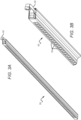
- hook 52 of a grow tower 50 includes a main body 53 and corresponding member 58 that engages groove 1002 as shown in Figures 5A and 8 . These hooks allow the grow towers 50 to hook into the groove 1002 and slide along the grow line 202 as discussed below.
- grow towers 50 can be manually unhooked from a grow line 202 and removed from production. This ability may be necessary if a crop in a grow tower 50 becomes diseased so that it does not infect other towers.
- the width of groove 1002 (for example, 13 mm) is an optimization between two different factors. First, the narrower the groove the more favorable the binding rate and the less likely grow tower hooks 52 are to bind. Conversely, the wider the groove the slower the grow tower hooks wear due to having a greater contact patch. Similarly, the depth of the groove, for example 10 mm, may be an optimization between space savings and accidental fallout of tower hooks.
- Hooks 52 may be injection-molded plastic parts.
- the plastic may be polyvinyl chloride (PVC), acrylonitrile butadiene styrene (ABS), or an Acetyl Homopolymer (e.g., Delrin ® sold by DuPont Company).
- the hook 52 may be solvent bonded to the top of the grow tower 50 and/or attached using rivets or other mechanical fasteners.
- the groove-engaging member 58 which rides in the rectangular groove 1002 of the grow line 202 may be a separate part or integrally formed with hook 52. If separate, this part can be made from a different material with lower friction and better wear properties than the rest of the hook, such as ultra-high-molecular weight polyethylene or acetal. To keep assembly costs low, this separate part may snap onto the main body of the hook 52. Alternatively, the separate part also be over-molded onto the main body of hook 52.
- the top section of the extrusion profile of grow line 202 contains a downward facing t-slot 1004.
- Linear guide carriages 610 ride within the t-slot 1004.
- the center portion of the t-slot 1004 may be recessed to provide clearance from screws or over-molded inserts which may protrude from the carriages 610.
- Each grow line 202 can be assembled from a number of separately fabricated sections. In one implementation, sections of grow line 202 are currently modeled in 6-meter lengths. Longer sections reduce the number of junctions but are more susceptible to thermal expansion issues and may significantly increase shipping costs. Additional features not captured by the Figures include intermittent mounting holes to attach the grow line 202 to the ceiling structure and to attach irrigation lines. Interruptions to the t-slot 1004 may also be machined into the conveyor body. These interruptions allow the linear guide carriages 610 to be removed without having to slide them all the way out the end of a grow line 202.
- a block 612 may be located in the t-slots 1004 of both conveyor bodies. This block serves to align the two grow line sections so that grow towers 50 may slide smoothly between them.
- Alternative methods for aligning sections of a grow line 202 include the use of dowel pins that fit into dowel holes in the extrusion profile of the section.
- the block 612 may be clamped to one of the grow line sections via a set screw, so that the grow line sections can still come together and move apart as the result of thermal expansion. Based on the relatively tight tolerances and small amount of material required, these blocks may be machined. Bronze may be used as the material for such blocks due to its strength, corrosion resistance, and wear properties.
- the vertical tower conveyance system 200 utilizes a reciprocating cam structure to move grow towers 50 along grow line 202.
- Figures 5A, 6 and 7 illustrate one possible reciprocating cam mechanism that can be used to move grow towers 50 across grow lines 202.
- Cams 602 physically push grow towers 50 along grow line 202.
- Cams 602 are attached to cam channel 604 (see below) and rotate about one axis. On the forward stroke, the rotation is limited by the top of the cam channel 604, causing the cams 602 to push grow towers 50 forward. On the reserve or back stroke, the rotation is unconstrained, thereby allowing the cams to ratchet over the top of the grow towers 50.
- a control system controls the operation of the reciprocating cam mechanism of each grow line 202 to move the grow towers 50 according to a programmed growing sequence. In between movement cycles, the actuator and reciprocating cam mechanism remain idle.
- the pivot point of the cams 602 and the means of attachment to the cam channel 604 consists of a binding post 606 and a hex head bolt 608; alternatively, detent clevis pins may be used.
- the hex head bolt 608 is positioned on the inner side of the cam channel 604 where there is no tool access in the axial direction. Being a hex head, it can be accessed radially with a wrench for removal. Given the large number of cams needed for a full-scale farm, a high-volume manufacturing process such as injection molding is suitable. ABS is suitable material given its stiffness and relatively low cost. All the cams 602 for a corresponding grow line 202 are attached to the cam channel 604.
- cam channel 604 When connected to an actuator, this common beam structure allows all cams 602 to stroke back and forth in unison.
- the structure of the cam channel 604 in one implementation, is a downward facing u-channel constructed from sheet metal. Holes in the downward facing walls of cam channel 604 provide mounting points for cams 602 using binding posts 606.
- cams 602 can be spaced relative to one another at any integer multiple of 12.7 mm, allowing for variable grow tower spacing with only one cam channel.
- the base of the cam channel 604 limits rotation of the cams during the forward stroke. All degrees of freedom of the cam channel 604, except for translation in the axial direction, are constrained by linear guide carriages 610 (described below) which mount to the base of the cam channel 604 and ride in the t-slot 1004 of the grow line 202.
- Cam channel 604 may be assembled from separately formed sections, such as sections in 6-meter lengths. Longer sections reduce the number of junctions but may significantly increase shipping costs.
- Linear guide carriages 610 are bolted to the base of the cam channels 604 and ride within the t-slots 1004 of the grow lines 202. In some implementations, one carriage 610 is used per 6-meter section of cam channel. Carriages 610 may be injection molded plastic for low friction and wear resistance. Bolts attach the carriages 610 to the cam channel 604 by threading into over molded threaded inserts. If select cams 602 are removed, these bolts are accessible so that a section of cam channel 604 can be detached from the carriage and removed.
- Sections of cam channel 604 are joined together with pairs of connectors 616 at each joint; alternatively, detent clevis pins may be used.
- Connectors 616 may be galvanized steel bars with machined holes at 20 mm spacing (the same hole spacing as the cam channel 604).
- Shoulder bolts 618 pass through holes in the outer connector, through the cam channel 604, and thread into holes in the inner connector. If the shoulder bolts fall in the same position as a cam 602, they can be used in place of a binding post. The heads of the shoulder bolts 618 are accessible so that connectors and sections of cam channel can be removed.
- cam channel 604 attaches to a linear actuator, which operates in a forward and a back stroke.
- a suitable linear actuator may be the T13-B4010MS053-62 actuator offered by Thomson, Inc. of Redford, Virginia; however, the reciprocating cam mechanism described herein can be operated with a variety of different actuators.
- the linear actuator may be attached to cam channel 604 at the off-loading end of a grow line 202, rather than the on-boarding end. In such a configuration, cam channel 604 is under tension when loaded by the towers 50 during a forward stroke of the actuator (which pulls the cam channel 604) which reduces risks of buckling.
- Figure 7A illustrates operation of the reciprocating cam mechanism according to one implementation of the invention.
- step A the linear actuator has completed a full back stroke; as Figure 7A illustrates, one or more cams 602 may ratchet over the hooks 52 of a grow tower 50.
- Step B of Figure 7A illustrates the position of cam channel 604 and cams 602 at the end of a forward stroke. During the forward stroke, cams 602 engage corresponding grow towers 50 and move them in the forward direction along grow line 202 as shown.
- Step C of Figure 7A illustrates how a new grow tower 50 (Tower 0) may be inserted onto a grow line 202 and how the last tower (Tower 9) may be removed.
- Step D illustrates how cams 602 ratchet over the grow towers 50 during a back stroke, in the same manner as Step A.
- the basic principle of this reciprocating cam mechanism is that reciprocating motion from a relatively short stroke of the actuator transports towers 50 in one direction along the entire length of the grow line 202. More specifically, on the forward stroke, all grow towers 50 on a grow line 202 are pushed forward one position. On the back stroke, the cams 602 ratchet over an adjacent tower one position back; the grow towers remain in the same location. As shown, when a grow line 202 is full, a new grow tower may be loaded and a last tower unloaded after each forward stroke of the linear actuator. In some implementations, the top portion of the hook 52 (the portion on which the cams push), is slightly narrower than the width of a grow tower 50.
- FIG. 7A shows 9 grow towers for didactic purposes.
- a grow line 202 can be configured to be quite long (for example, 40 meters) allowing for a much greater number of towers 50 on a grow line 202 (such as 400-450).
- the minimum tower spacing can be set equal to or slightly greater than two times the side-to-side distance of a grow tower 50 to allow more than one grow tower 50 to be loaded onto a grow line 202 in each cycle.
- the spacing of cams 602 along the cam channel 604 can be arranged to effect one-dimensional plant indexing along the grow line 202.
- the cams 602 of the reciprocating cam mechanism can be configured such that spacing between towers 50 increases as they travel along a grow line 202.
- spacing between cams 602 may gradually increase from a minimum spacing at the beginning of a grow line to a maximum spacing at the end of the grow line 202. This may be useful for spacing plants apart as they grow to increase light interception and provide spacing, and, through variable spacing or indexing, increasing efficient usage of the growth chamber 20 and associated components, such as lighting.
- the forward and back stroke distance of the linear actuator is equal to (or slightly greater than) the maximum tower spacing.
- cams 602 at the beginning of a grow line 202 may ratchet and overshoot a grow tower 50.
- cams located further along the grow line 202 may travel shorter distances before engaging a tower or engage substantially immediately.
- the maximum tower spacing cannot be two times greater than the minimum tower spacing; otherwise, a cam 602 may ratchet over and engage two or more grow towers 50.
- an expansion joint may be used, as illustrated in Figure 7B .
- expansion joint 710 allows the leading section of the cam channel 604 to begin traveling before the trailing end of the cam channel 604, thereby achieving a long stroke.
- expansion joint 710 may attach to sections 604a and 604b of cam channel 604.
- the expansion joint 710 In the initial position (702), the expansion joint 710 is collapsed.
- the leading section 604a of cam channel 604 moves forward (as the actuator pulls on cam channel 604), while the trailing section 604b remains stationary.
- the trailing section 604 of cam channel 604 begins to move forward as well.
- the expansion joint 710 collapses to its initial position.
- the leading section 604a moves backward, while the trailing section remains stationary, until the expansion joint reaches the initial, collapsed position.
- a lead screw mechanism may be employed.
- the threads of the lead screw engage hooks 52 disposed on grow line 202 and move grow towers 50 as the shaft rotates.
- the pitch of the thread may be varied to achieve one-dimensional plant indexing.
- a belt conveyor include paddles along the belt may be employed to move grow towers 50 along a grow line 202.
- a power-and-free conveyor may be employed to move grow towers 50 along a grow line 202.
- the grow line 202 illustrated in the various figures is horizontal to the ground, the grow line 202 may be sloped at a slight angle, either downwardly or upwardly relative to the direction of tower travel. Still further, while the grow line 202 described above operates to convey grow towers in a single direction, the grow line 202 may be configured to include multiple sections, where each section is oriented in a different direction. For example, two sections may be perpendicular to each other. In other implementations, two sections may run parallel to each other, but have opposite directions of travel.
- FIG 8 illustrates how an irrigation line 802 may be attached to grow line 202 to supply an aqueous nutrient solution to crops disposed in grow towers 50 as they translate through the vertical tower conveyance system 200.
- Irrigation line 802 in one implementation, is a pressurized line with spaced-apart openings or holes disposed at the expected locations of the towers 50 as they advance along grow line 202 with each movement cycle.
- the irrigation line 802 may be a PVC pipe having an inner diameter of 38,1mm (1.5 inches) and holes having diameters of 3,17mm (0.125 inches).
- the irrigation line 802 may be approximately 40 meters in length spanning the entire length of a grow line 202. To ensure adequate pressure across the entire line, irrigation line 802 may be broken into shorter sections, each connected to a manifold, so that pressure drop is reduced.
- a funnel structure 902 collects aqueous nutrient solution from irrigation line 802 and distributes the aqueous nutrient solution to the cavity(ies) 54a, 54b of the grow tower 50 as discussed in more detail below.
- Figures 9 and 11A illustrate that the funnel structure 902 may be integrated into hook 52.
- the funnel structure 902 may include a collector 910, first and second passageways 912 and first and second slots 920.
- the groove-engaging member 58 of the hook may disposed at a centerline of the overall hook structure.
- the funnel structure 902 may include flange sections 906 extending downwardly opposite the collector 910 and on opposing sides of the centerline.
- the outlets of the first and second passageways are oriented substantially adjacent to and at opposing sides of the flange sections 906, as shown.
- Flange sections 906 register with central wall 56 of grow tower 50 to center the hook 52 and provides additional sites to adhere or otherwise attach hook 52 to grow tower 50.
- central wall 56 is disposed between flange sections 906.
- collector 910 extends laterally from the main body 53 of hook 52.
- funnel structure 902 includes a collector 910 that collects nutrient fluid and distributes the fluid evenly to the inner cavities 54a and 54b of tower through passageways 912. Passageways 912 are configured to distribute aqueous nutrient solution near the central wall 56 and to the center back of each cavity 54a, 54b over the ends of the plug holders 158 and where the roots of a planted crop are expected.
- the funnel structure 902 includes slots 920 that promote the even distribution of nutrient fluid to both passageways 912. For nutrient fluid to reach passageways 912, it must flow through one of the slots 920.
- Each slot 920 may have a V-like configuration where the width of the slot opening increases as it extends from the substantially flat bottom surface 922 of collector 910.
- each slot 920 may have a width of 1 millimeter at the bottom surface 922.
- the width of slot 920 may increase to 5 millimeters over a height of 25 millimeters.
- the configuration of the slots 920 causes nutrient fluid supplied at a sufficient flow rate by irrigation line 802 to accumulate in collector 910, as opposed to flowing directly to a particular passageway 912, and flow through slots 920 to promote even distribution of nutrient fluid to both passageways 912.
- irrigation line 802 provides aqueous nutrient solution to funnel structure 902 that even distributes the water to respective cavities 54a, 54b of grow tower 50.
- the aqueous nutrient solution supplied from the funnel structure 902 irrigates crops contained in respective plug containers 158 as it trickles down.
- a gutter disposed under each grow line 202 collects excess water from the grow towers 50 for recycling.
- the funnel structure may be configured with two separate collectors that operate separately to distribute aqueous nutrient solution to a corresponding cavity 54a, 54b of a grow tower 50.
- the irrigation supply line can be configured with one hole or aperture for each collector.
- an emitter structure or nozzle may be attached to each hole or aperture.
- the towers may only include a single cavity and include plug containers only on a single face 101 of the towers. Such a configuration still calls for a use of a funnel structure that directs aqueous nutrient solution to a desired portion of the tower cavity, but obviates the need for separate collectors or other structures facilitating even distribution.
Landscapes
- Life Sciences & Earth Sciences (AREA)
- Environmental Sciences (AREA)
- Engineering & Computer Science (AREA)
- Water Supply & Treatment (AREA)
- Soil Sciences (AREA)
- Mechanical Engineering (AREA)
- Hydroponics (AREA)
- Cultivation Of Plants (AREA)
- Cultivation Receptacles Or Flower-Pots, Or Pots For Seedlings (AREA)
Claims (9)
- Système de production agricole pour une agriculture en environnement contrôlé, comprenant :une ou plusieurs lignes de culture (202), chacune des une ou plusieurs lignes de culture comprenant un mécanisme de transport de culture (200) ; etune pluralité de tours de culture (50), chacune de la pluralité de tours de culture étant fixée verticalement à, et mobile le long d'une ligne de culture respective des une ou plusieurs lignes de culture (202) ;dans lequel chacun des un ou plusieurs mécanismes de transport (200) comprend :un longeron commun (604) disposé dans une voie, la voie s'étendant dans une direction parallèle à la ligne de culture ;un actionneur fixé au longeron commun (604), dans lequel l'actionneur est opérationnel pour déplacer le longeron commun le long de la voie dans une course vers l'avant et une course vers l'arrière ; etune pluralité de cames (602) fixées de manière pivotante au niveau de positions choisies le long du longeron commun (604), dans lequel chaque came est montée pour limiter une rotation de la came pendant la course vers l'avant, amenant la came à venir en prise avec une première tour (50) et à pousser celle-ci vers l'avant dans une première direction pendant la course vers l'avant et pour permettre à la came de coulisser sur une seconde tour (50) pendant la course vers l'arrière ;dans lequel les positions choisies de la pluralité de cames (602) sont chacune conçues de sorte que dans une course vers l'avant, une came respective vient en prise avec une première tour de culture (50) pendant la course vers l'avant et assure l'encliquetage sur une seconde tour de culture (50) adjacente à la première tour pendant la course vers l'arrière.
- Système de production agricole selon la revendication 1, dans lequel l'espacement des positions choisies augmente dans la première direction de sorte qu'un espacement des tours de culture (50) augmente à mesure que ces tours de culture sont poussées le long d'une ou de plusieurs lignes de culture avec des cycles successifs de l'actionneur.
- Système de production agricole selon la revendication 1, dans lequel le longeron commun (604) a un profil en forme de U ayant des première et seconde parois s'étendant depuis une base, et dans lequel la pluralité de cames (602) sont chacune montées au niveau des positions choisies le long des première et seconde parois.
- Système de production agricole selon la revendication 1, dans lequel chacune de la pluralité de tours de culture (50) comprend un crochet (52) fixé au sommet de la tour de culture, dans lequel le crochet est conçu pour venir en prise avec la ligne de culture (202).
- Système de production agricole selon la revendication 4, dans lequel chacune des une ou plusieurs lignes de culture (202) comporte une région de rainure (1002) à laquelle le crochet (52) d'une tour de culture (50) se fixe de manière coulissante.
- Système de production agricole selon la revendication 1, dans lequel chacune de la pluralité de tours de culture (50) comprend une première pluralité de contenants de motte (158) agencés le long d'une première face (101) de la tour de culture.
- Système de production agricole selon la revendication 6, dans lequel chacune de la pluralité de tours de culture (50) comprend une seconde pluralité de contenants de motte (158) agencés le long d'une seconde face (101) de la tour de culture, dans lequel la seconde face est opposée à la première face.
- Système de production agricole selon la revendication 1, comprenant en outre un mécanisme de chargement (47) comprenant un convoyeur motorisé et libre et un ou plusieurs chariots (1202) ; dans lequel les un ou plusieurs chariots sont conçus pour venir en prise de manière amovible avec des tours de culture (50) ; et dans lequel le convoyeur motorisé et libre (47) est conçu pour insérer des tours de culture sur une ligne de culture (202) choisie des une ou plusieurs lignes de culture.
- Système de production agricole selon la revendication 2, dans lequel le longeron commun (604) comprend une première section de longeron (604a), une seconde section de longeron (604b) et un compensateur de dilatation (710) fixé à des extrémités opposées des première et seconde sections de longeron, dans lequel le compensateur de dilatation est mobile depuis une position repliée vers une position ouverte et conçu de sorte que, pendant la course vers l'avant, le compensateur de dilatation se déplace depuis la position repliée vers la position ouverte, amenant ainsi la première section de longeron (604a) à se déplacer vers l'avant tandis que la seconde section de longeron (604b) reste fixe jusqu'à ce que le compensateur de dilatation soit dans la position ouverte et, pendant la course vers l'arrière, le compensateur de dilatation se déplace depuis la position ouverte vers la position repliée.
Priority Applications (1)
| Application Number | Priority Date | Filing Date | Title |
|---|---|---|---|
| EP22215490.8A EP4197317A1 (fr) | 2018-03-21 | 2019-03-20 | Système de transport de tour de culture verticale multi compartiments |
Applications Claiming Priority (3)
| Application Number | Priority Date | Filing Date | Title |
|---|---|---|---|
| US201862761366P | 2018-03-21 | 2018-03-21 | |
| US201862752974P | 2018-10-30 | 2018-10-30 | |
| PCT/US2019/023201 WO2019183244A2 (fr) | 2018-03-21 | 2019-03-20 | Système de transport de tours de croissance verticales pour agriculture à environnement contrôlé |
Related Child Applications (2)
| Application Number | Title | Priority Date | Filing Date |
|---|---|---|---|
| EP22215490.8A Division-Into EP4197317A1 (fr) | 2018-03-21 | 2019-03-20 | Système de transport de tour de culture verticale multi compartiments |
| EP22215490.8A Division EP4197317A1 (fr) | 2018-03-21 | 2019-03-20 | Système de transport de tour de culture verticale multi compartiments |
Publications (3)
| Publication Number | Publication Date |
|---|---|
| EP3768071A2 EP3768071A2 (fr) | 2021-01-27 |
| EP3768071B1 true EP3768071B1 (fr) | 2023-06-07 |
| EP3768071C0 EP3768071C0 (fr) | 2023-06-07 |
Family
ID=66001379
Family Applications (2)
| Application Number | Title | Priority Date | Filing Date |
|---|---|---|---|
| EP19715343.0A Active EP3768071B1 (fr) | 2018-03-21 | 2019-03-20 | Système de transport de tours de croissance verticales pour agriculture à environnement contrôlé |
| EP22215490.8A Pending EP4197317A1 (fr) | 2018-03-21 | 2019-03-20 | Système de transport de tour de culture verticale multi compartiments |
Family Applications After (1)
| Application Number | Title | Priority Date | Filing Date |
|---|---|---|---|
| EP22215490.8A Pending EP4197317A1 (fr) | 2018-03-21 | 2019-03-20 | Système de transport de tour de culture verticale multi compartiments |
Country Status (8)
| Country | Link |
|---|---|
| US (3) | US11089741B2 (fr) |
| EP (2) | EP3768071B1 (fr) |
| JP (2) | JP7299232B2 (fr) |
| KR (1) | KR20200140803A (fr) |
| CN (2) | CN112105256B (fr) |
| AU (2) | AU2019240064B2 (fr) |
| SG (1) | SG11202007903UA (fr) |
| WO (1) | WO2019183244A2 (fr) |
Families Citing this family (18)
| Publication number | Priority date | Publication date | Assignee | Title |
|---|---|---|---|---|
| JP7299232B2 (ja) * | 2018-03-21 | 2023-06-27 | エムジェイエヌエヌ, エルエルシー | 環境制御農業用の垂直栽培タワー搬送システム |
| WO2020092506A1 (fr) | 2018-10-30 | 2020-05-07 | Mjnn Llc | Agencement d'installation de production pour une agriculture à environnement contrôlé automatisé |
| JP7473542B2 (ja) * | 2018-10-30 | 2024-04-23 | エムジェイエヌエヌ, エルエルシー | 環境制御農業システム用の栽培タワー処理 |
| TWI766160B (zh) * | 2019-04-26 | 2022-06-01 | 元通光電科技股份有限公司 | 人工智慧植物工廠一貫自動化採收系統及植栽回流裝置 |
| EP3965559A4 (fr) | 2019-05-09 | 2023-04-26 | 80 Acres Urban Agriculture Inc. | Procédé et appareil d'agriculture en intérieur haute-densité |
| WO2020232151A1 (fr) | 2019-05-13 | 2020-11-19 | 80 Acres Urban Agriculture, Inc. | Système et procédé de commande de fermes intérieures à distance et interface utilisateur associée |
| CA3161029A1 (fr) | 2019-09-20 | 2021-03-25 | Gage Goodspeed COFFIN | Agencements d'installation de production pour une agriculture a environnement controle automatise |
| CN114423280B (zh) | 2019-09-20 | 2023-02-03 | Mjnn有限责任公司 | 用于受控环境农业的作物生产系统及相关联方法 |
| US11570958B2 (en) | 2019-09-20 | 2023-02-07 | Mjnn Llc | Catch mechanism facilitating loading of vertical grow towers onto grow lines in a vertical farm system |
| US20210137037A1 (en) * | 2019-11-12 | 2021-05-13 | Fork Farms Holdings, Llc | Hydroponic growth system and assembly |
| GB2590712B (en) * | 2019-12-30 | 2023-11-22 | Seven Seas Productions Ltd | Hydroponic apparatus |
| RU2735220C1 (ru) * | 2020-04-21 | 2020-10-28 | Общество с ограниченной ответственностью "Городские агротехнологии" (ООО "Городские агротехнологии") | Способ выращивания растениеводческой продукции в вертикально ориентированных тепличных комплексах |
| US11211538B1 (en) | 2020-12-23 | 2021-12-28 | Joseph L. Pikulski | Thermal management system for electrically-powered devices |
| KR102241200B1 (ko) * | 2020-12-28 | 2021-04-16 | (주)코트론 | 수직형 수경재배기 |
| US20220287256A1 (en) * | 2021-03-12 | 2022-09-15 | NW Farms, Inc. | Vertically oriented plant beds for use with a hydroponic system |
| WO2023004320A1 (fr) * | 2021-07-21 | 2023-01-26 | Mjnn Llc | Indexage vertical de segments de tour de croissance |
| CN114673966A (zh) * | 2022-04-14 | 2022-06-28 | 北京金晟达生物电子科技有限公司 | 一种便于更换光照模组的旋转塔 |
| CN115474542B (zh) * | 2022-09-26 | 2023-08-15 | 北京中农富通园艺有限公司 | 一种水培自动化系统 |
Family Cites Families (127)
| Publication number | Priority date | Publication date | Assignee | Title |
|---|---|---|---|---|
| US2244677A (en) | 1937-07-06 | 1941-06-10 | Fay D Cornell | System of plant production |
| US3254448A (en) | 1964-03-23 | 1966-06-07 | Ruthner Othmar | Installation for the artificial cultivation of plants, bacteria and other organisms |
| US3719327A (en) | 1971-08-13 | 1973-03-06 | Mcmahan Brothers Mfg Co Inc | Drip irrigation nozzle |
| IT1008055B (it) | 1972-10-13 | 1976-11-10 | Hydroculture | Sistema di coltivazione agricola idroponica |
| US4454684A (en) | 1983-03-16 | 1984-06-19 | Hare Louis R O | Root augmentor for vertical horticulture |
| US4965962A (en) | 1984-11-21 | 1990-10-30 | Q. P. Corporation | Hydroponic culture system |
| JPH0614663B2 (ja) | 1986-09-19 | 1994-02-23 | 株式会社リコー | 光走査装置 |
| JP2529803B2 (ja) * | 1992-07-02 | 1996-09-04 | タバイエスペック株式会社 | 植物体移動装置 |
| FR2700918B1 (fr) * | 1993-02-03 | 1995-04-21 | Geraflor | Installation pour la culture hors-sol de plantes. |
| US5617673A (en) | 1993-11-17 | 1997-04-08 | Takashima; Yasukazu | Gravity independent photosynthetic growing system |
| US5555676A (en) | 1994-11-03 | 1996-09-17 | A.C.T., Inc. | Vertical planter apparatus and method |
| US5502923A (en) | 1995-04-25 | 1996-04-02 | Bradshaw; John A. | Hydroponic growth systems and methods |
| US6061957A (en) | 1998-05-14 | 2000-05-16 | Takashima; Yasukazu | Plant growth system with collapsible rib structure |
| AU2001244736A1 (en) | 2000-07-07 | 2002-01-21 | Cosmo Plant Co., Ltd | Method of producing plants, plant cultivating device, and light-emitting panel |
| US6276410B1 (en) * | 2000-09-21 | 2001-08-21 | Stephen G. Esmeralda | Oil funnel assembly |
| JP2006507848A (ja) * | 2002-11-27 | 2006-03-09 | リン,スン−ホ | 養液栽培装置及びそれに使用される養液栽培ポート |
| KR200313390Y1 (ko) * | 2002-11-27 | 2003-05-14 | 임선호 | 양액재배포트 |
| US20040103583A1 (en) | 2002-12-03 | 2004-06-03 | Eriksen Martin Woergaard | Hanging garden planter |
| DE602004005118D1 (de) | 2003-09-17 | 2007-04-19 | Air Quality Solutions Ltd | Träger für eine vertikale hydroponische Pflanzenmatrix |
| JP2008500062A (ja) | 2004-05-24 | 2008-01-10 | ファウンテンヘッド,エルエルシー | 超拡大、浮力調整型浮島 |
| WO2006096650A2 (fr) | 2005-03-07 | 2006-09-14 | Terrasphere Systems Llc | Procede et appareil de culture de plantes |
| CA2499512A1 (fr) | 2005-03-07 | 2006-09-07 | Terrasphere Systems Llc | Methode et dispositif de culture des plantes |
| US7559173B2 (en) | 2005-03-07 | 2009-07-14 | Terrasphere Systems Llc | Method and apparatus for growing plants in carousels |
| US20060201058A1 (en) | 2005-03-09 | 2006-09-14 | Ripatti Matti T | Multipurpose growing system |
| US7785207B2 (en) | 2005-04-20 | 2010-08-31 | Water Ride Concepts, Inc. | Water amusement system with elevated structure |
| CN101472465B (zh) | 2006-03-06 | 2011-07-06 | 高架景观科技公司 | 垂直植物支架系统 |
| NL1031559C2 (nl) * | 2006-04-10 | 2007-10-11 | Logiqs Agro B V | Gewasdrager, gewasondersteuning en teeltsysteem. |
| WO2008022312A2 (fr) | 2006-08-17 | 2008-02-21 | Algepower, Llc | Enceinte de développement hydroponique et procédé de développement, de récolte, de traitement et de distribution d'algues, de microorganismes apparentés et de leurs sous-produits |
| US20080086942A1 (en) | 2006-10-14 | 2008-04-17 | Martin Donald Maier | Low profile office partition planter |
| US8122642B1 (en) | 2008-02-13 | 2012-02-28 | EZ Care Growing Technologies, LLC. | Horticultural growth medium |
| US8074398B2 (en) | 2008-03-20 | 2011-12-13 | Haim Hazan | Growing system for enhanced yield |
| US8151518B2 (en) | 2008-06-17 | 2012-04-10 | New York Sun Works | Vertically integrated greenhouse |
| US8234814B2 (en) * | 2008-07-29 | 2012-08-07 | Malcolm Glen Kertz | Plant growing assembly |
| CA2753766A1 (fr) * | 2009-02-27 | 2010-09-02 | Valcent Products (Eu) Limited | Appareil utilisable pour la culture de plantes |
| US10638677B2 (en) | 2009-08-03 | 2020-05-05 | University Of Wyoming | Vertical hydroponic plant production apparatus |
| US9491915B2 (en) | 2009-08-03 | 2016-11-15 | University Of Wyoming | Vertical hydroponic plant production apparatus |
| US11026378B2 (en) | 2009-08-03 | 2021-06-08 | University Of Wyoming | Vertical hydroponic plant production apparatus |
| US9380751B2 (en) | 2009-08-03 | 2016-07-05 | University Of Wyoming | Vertical hydroponic plant production apparatus |
| WO2011016856A1 (fr) | 2009-08-03 | 2011-02-10 | University Of Wyoming | Appareil vertical pour la production hydroponique de plantes |
| US8141294B2 (en) | 2009-09-05 | 2012-03-27 | Christopher James Bribach | Vertical garden panel |
| US8250809B2 (en) | 2009-09-11 | 2012-08-28 | Robert Simmons | Apparatus for aeroponically growing and developing plants |
| US20110131876A1 (en) | 2009-11-22 | 2011-06-09 | Glen James Pettibone | Combined Vertical Farm, Biofuel, Biomass, and Electric Power Generation Process and Facility |
| US9504209B2 (en) | 2010-04-09 | 2016-11-29 | Rain Bird Corporation | Irrigation sprinkler nozzle |
| US20130067814A1 (en) | 2010-05-27 | 2013-03-21 | Britta Riley | Hydroponic system |
| US8689485B2 (en) | 2010-12-15 | 2014-04-08 | Inventurous, LLC | Vertical planter and gardening wall |
| US20120167460A1 (en) | 2010-12-31 | 2012-07-05 | Julian Omidi | Cultivation system for medicinal vegetation |
| AU2012253156B2 (en) | 2011-05-06 | 2016-11-24 | Cubicfarm Systems Corp. | Method and apparatus for growing plants along an undulating path |
| US20120285084A1 (en) | 2011-05-11 | 2012-11-15 | Pang-Ling Hu | Vertical garden assembly |
| CA2853757A1 (fr) | 2011-07-07 | 2013-01-10 | Tim Dewey Carpenter | Agencement et procede de croissance pour jardiniere verticale |
| US20130019527A1 (en) | 2011-07-21 | 2013-01-24 | Ingrid Howe-Sylvain | Mobile, Automatic Plant Growth System |
| US9043962B2 (en) | 2012-01-13 | 2015-06-02 | Danielle Trofe Design, Llc | Modular self-sustaining planter system |
| KR20140124801A (ko) | 2012-01-30 | 2014-10-27 | 버티컬 디자인스 엘티디. | 자동화된 원예 및 영농을 위한 방법 및 장치 |
| US20130298462A1 (en) | 2012-05-14 | 2013-11-14 | Sean Thomas Moran | Modular plant growing system for food production and decoration, and methodology for use. |
| US10136594B2 (en) | 2012-05-18 | 2018-11-27 | Tower Garden, Llc | Aeroponic growing system and method |
| WO2013184224A1 (fr) | 2012-06-08 | 2013-12-12 | Living Greens Farm, Inc. | Système d'irrigation |
| EP2858477B1 (fr) | 2012-06-08 | 2021-08-04 | Living Greens Farm, Inc. | Système d'irrigation pour utilisation dans un environnement contrôlé |
| MX2012008531A (es) | 2012-07-23 | 2012-12-05 | Luis Hector Alberto Martinez Ruanova | Unidad colgante vertical en forma de bolsas para cultivo hidroponico de plantas y un panel de unidades colgantes verticales en forma de bolsas para cultivo hidroponico. |
| EP2901849A4 (fr) | 2012-09-27 | 2016-08-17 | Toyo Tire & Rubber Co | Particules de sol artificiel, agrégats de sol artificiel, corps moulé à base de sol artificiel, tapis végétal, panneau pour mur végétal et blocs de jardinage utilisant un corps moulé à base de sol artificiel |
| CN102893799A (zh) * | 2012-11-02 | 2013-01-30 | 北京工业大学 | 自动化蔬菜种植与收获生产线 |
| US9359759B2 (en) | 2012-11-30 | 2016-06-07 | Eleven Solutions Rfe S.A. De C.V. | Ecological construction systems for buildings with green walls |
| JP6367828B2 (ja) | 2013-01-11 | 2018-08-01 | フィリップス ライティング ホールディング ビー ヴィ | 植物の成長及び植物のバイオリズムを刺激する園芸用照明装置並びに方法 |
| US20140223816A1 (en) | 2013-02-12 | 2014-08-14 | Bobby M. Parker | Vertical gardening apparatus |
| WO2014152953A1 (fr) | 2013-03-14 | 2014-09-25 | Sealy Technology, Llc | Système de fabrication et d'assemblage de ressort intérieur et éléments pour l'orientation de spire sélectionnable, le réglage de position et le transport de spire |
| US20140259904A1 (en) | 2013-03-15 | 2014-09-18 | William Charles Collard | System and process for irrigating and monitoring the growth of plants |
| US9374952B1 (en) | 2013-03-15 | 2016-06-28 | John Thomas Cross | Rotatable vertical growing system |
| WO2014144368A1 (fr) | 2013-03-15 | 2014-09-18 | Zbode, Llc | Appareils, systèmes et procédés pour espaces d'habitation transformables |
| US8627598B1 (en) * | 2013-03-15 | 2014-01-14 | Sprouting Works, LLC | Sprouted seed grain growing and harvesting apparatus and method |
| GB201304996D0 (en) | 2013-03-19 | 2013-05-01 | Nedlaw Living Walls Inc | In-room hydroponic air cleansing unit |
| US20140318010A1 (en) | 2013-04-25 | 2014-10-30 | David J. Tomlinson | Modular Tensile Vegetated Wall System |
| WO2015123587A1 (fr) | 2014-02-13 | 2015-08-20 | Fred Collins | Procédé et système modulaires légers réglables verticaux de culture hydroponique |
| CA2940062C (fr) | 2014-02-20 | 2022-05-03 | Affinor Growers Inc. | Procede et appareil d'horticulture et d'agriculture verticales automatisees |
| US9730400B2 (en) | 2014-03-20 | 2017-08-15 | Gro-Volution, Llc | Three dimensional vegetation growing systems |
| US9357715B2 (en) | 2014-05-01 | 2016-06-07 | Brian Cottrell | Vertical planter |
| WO2015175415A1 (fr) | 2014-05-11 | 2015-11-19 | University Of Wyoming | Système à râtelier hydroponique modulaire pour la culture et le transport de végétaux |
| US10499575B2 (en) | 2014-05-22 | 2019-12-10 | Aero Development Corp. | Modular aeroponic growing column and system |
| AU2015269088B2 (en) | 2014-06-06 | 2017-11-30 | RackREIT, LLC | System and method for cultivating plants |
| TWM494487U (zh) * | 2014-07-18 | 2015-02-01 | Huang Maggie | 直立式栽培器及直立式栽培裝置 |
| WO2016015152A1 (fr) | 2014-07-31 | 2016-02-04 | Mark Nelson | Ensemble pour réseau végétal vertical |
| CN107072156B (zh) | 2014-07-31 | 2022-07-12 | 生活绿色农场股份有限公司 | 生长系统 |
| JP5880901B2 (ja) * | 2014-08-29 | 2016-03-09 | 富士通株式会社 | 水耕栽培方法 |
| US10172301B2 (en) | 2014-09-11 | 2019-01-08 | Freight Farms, Inc. | Insulated shipping containers modified for high-yield fungi production capable in any environment |
| AT14614U1 (de) * | 2014-11-07 | 2016-02-15 | Hoffmann Arne | Pflanzenhalte- und Bewässerungssystem |
| US20160135398A1 (en) | 2014-11-17 | 2016-05-19 | Bellwether Innovations, Llc | Vertical growing system and method |
| US10094116B2 (en) | 2015-01-01 | 2018-10-09 | Aravinda Raama Mawendra | Central processing horticulture |
| US10201122B2 (en) | 2015-01-23 | 2019-02-12 | Kevin W. Higgins | Large-scale helical farming apparatus |
| US20160212946A1 (en) | 2015-01-23 | 2016-07-28 | Kevin W. Higgins | Large-scale helical farming apparatus |
| JP6876891B2 (ja) * | 2015-02-13 | 2021-06-02 | 伊東電機株式会社 | 植物栽培装置及び植物栽培システム |
| US20160235025A1 (en) | 2015-02-15 | 2016-08-18 | Azoth Solutions, LLC | Aeroponic Cultivation System |
| CA2882972A1 (fr) | 2015-02-24 | 2016-08-24 | Gaston Beaulieu | Serre multietage a ecosysteme ferme destinee a la production industrielle integree verticalement |
| RU2708795C2 (ru) * | 2015-03-19 | 2019-12-12 | Рокеха Лтд. | Система культивации растений в помещении в условиях, имитирующих естественное освещение |
| WO2016154360A1 (fr) | 2015-03-24 | 2016-09-29 | Smarter Planet Enterprises Corporation | Biosystème agraire portatif |
| WO2016164652A1 (fr) | 2015-04-09 | 2016-10-13 | Growx Inc. | Systèmes, procédés et dispositifs pour ensemble de diodes électroluminescentes et appareil d'horticulture |
| EP3287004A4 (fr) | 2015-04-21 | 2019-07-10 | Tsubakimoto Chain Co. | Dispositif de transplantation, système de transplantation et procédé de transplantation, et programme informatique |
| EP3302026A4 (fr) | 2015-05-26 | 2019-01-23 | Delos Living LLC | Système modulaire de mur végétalisé |
| US10485193B2 (en) | 2015-05-28 | 2019-11-26 | Robert V. Neuhoff, JR. | Automated hydroponics system and method |
| HK1203026A2 (en) * | 2015-06-26 | 2015-10-09 | 馮志華 | Vertical tower for organic farming |
| US10736284B2 (en) | 2015-09-01 | 2020-08-11 | Keith Baker | Vertical hydroponic system |
| CA2908823A1 (fr) | 2015-09-09 | 2017-03-09 | Zale Lewis David Tabakman | Methode et module de croissance de legumes dans un environnement ferme |
| US10047943B2 (en) | 2015-11-19 | 2018-08-14 | Minn, Llc | Water-cooled LED lighting system for indoor farming |
| US9924639B1 (en) | 2015-12-15 | 2018-03-27 | Chandler A. Arrighi | Temperature control structure for indoor gardens |
| US10390503B2 (en) | 2016-01-20 | 2019-08-27 | Stephen A. Dufresne | Automated mobile terrace growing system |
| US10390504B2 (en) | 2016-07-08 | 2019-08-27 | Stephen A. Dufresne | Multilevel mobile gutter system for growing indoor vegetation |
| US10618530B2 (en) * | 2016-04-08 | 2020-04-14 | Still Water Designs, Inc. | System for growing plants |
| US20170339841A1 (en) | 2016-05-31 | 2017-11-30 | Fernando Ortiz Monasterio | System and method for modular garden |
| JP6812668B2 (ja) * | 2016-06-17 | 2021-01-13 | 東洋製罐グループホールディングス株式会社 | 水耕栽培システム |
| WO2018013163A1 (fr) | 2016-07-14 | 2018-01-18 | Mjnn Llc | Systèmes de commande et de détection destinés à un système d'agriculture verticale climatisé |
| CN206061848U (zh) * | 2016-08-19 | 2017-04-05 | 肖洪英 | 一种养鸡用鸡群饮水设备 |
| US20180077884A1 (en) | 2016-09-19 | 2018-03-22 | Econow Systems, LLC | Apparatus And Method For Automated Aeroponic Systems For Growing Plants |
| US10765071B2 (en) | 2016-09-29 | 2020-09-08 | Mariplast North America, Inc. | Enclosing vegetative sheath |
| US20180098513A1 (en) | 2016-10-06 | 2018-04-12 | Brian Richie Designs Incorporated | Growth Efficiency System |
| US10327399B2 (en) | 2016-11-29 | 2019-06-25 | Invia Robotics, Inc. | Harvesting robots for hydroponics |
| US10772271B2 (en) | 2016-12-06 | 2020-09-15 | Mjnn, Llc | Rapid transplanting system |
| US20180153115A1 (en) | 2016-12-07 | 2018-06-07 | Rajesh Edke | Appratus for crop/plant/life-form cultivation |
| US20180168108A1 (en) | 2016-12-16 | 2018-06-21 | Robert Neil H. Foreman | Modular plant growth system |
| CN106508654B (zh) * | 2016-12-22 | 2019-12-06 | 江苏省农业科学院 | 适于发根农杆菌转基因组合植株根系培养的专用水培装置 |
| CN206821390U (zh) * | 2017-01-16 | 2018-01-02 | 深圳市绿意生态环境科技有限公司 | 室内空气净化植物墙 |
| US10136587B1 (en) * | 2017-10-12 | 2018-11-27 | Gary Lind Johnson | Agricultural apparatus and method |
| CA2986879A1 (fr) | 2017-11-28 | 2019-05-28 | Warren Vesty | Mecanisme de croissance vegetale a recirculation |
| NL2020300B1 (en) * | 2018-01-22 | 2019-07-29 | Visser S Gravendeel Holding B V | Container, such as a tray or strip, with cutting edges |
| US10701875B2 (en) | 2018-03-02 | 2020-07-07 | Mjnn, Llc | Multi-piece hydroponic tower with hinged tower face |
| US10986791B2 (en) | 2018-03-02 | 2021-04-27 | Mjnn Llc | Hydroponic tower compatible plant plug holder |
| US20190269080A1 (en) | 2018-03-02 | 2019-09-05 | Mjnn, Llc | Hydroponic Tower Compatible Plant Container |
| JP7299232B2 (ja) * | 2018-03-21 | 2023-06-27 | エムジェイエヌエヌ, エルエルシー | 環境制御農業用の垂直栽培タワー搬送システム |
| US11602106B2 (en) | 2018-07-06 | 2023-03-14 | Eden Green Global Technologies Limited | Hydroponics |
| US11673080B2 (en) * | 2019-06-04 | 2023-06-13 | Michael F. Dolan | Fluid filling diverter and collector apparatus |
| US11284573B2 (en) * | 2019-07-08 | 2022-03-29 | Cecil Logan Ellsworth | Modular hydroponic growing apparatus and system |
| US11027955B2 (en) * | 2019-09-26 | 2021-06-08 | Gerald J Pelle | Apparatus for the transfer and preservation of juices |
-
2019
- 2019-03-20 JP JP2020551334A patent/JP7299232B2/ja active Active
- 2019-03-20 AU AU2019240064A patent/AU2019240064B2/en active Active
- 2019-03-20 KR KR1020207025953A patent/KR20200140803A/ko not_active Application Discontinuation
- 2019-03-20 WO PCT/US2019/023201 patent/WO2019183244A2/fr unknown
- 2019-03-20 EP EP19715343.0A patent/EP3768071B1/fr active Active
- 2019-03-20 US US16/982,549 patent/US11089741B2/en active Active
- 2019-03-20 CN CN201980017206.6A patent/CN112105256B/zh active Active
- 2019-03-20 EP EP22215490.8A patent/EP4197317A1/fr active Pending
- 2019-03-20 CN CN202210656063.7A patent/CN114847153A/zh active Pending
- 2019-03-20 SG SG11202007903UA patent/SG11202007903UA/en unknown
-
2021
- 2021-07-12 US US17/372,751 patent/US11690326B2/en active Active
- 2021-07-12 US US17/372,739 patent/US11612112B2/en active Active
-
2023
- 2023-03-23 JP JP2023046874A patent/JP2023068144A/ja active Pending
-
2024
- 2024-04-11 AU AU2024202370A patent/AU2024202370A1/en active Pending
Also Published As
| Publication number | Publication date |
|---|---|
| EP3768071A2 (fr) | 2021-01-27 |
| US20210000022A1 (en) | 2021-01-07 |
| JP7299232B2 (ja) | 2023-06-27 |
| WO2019183244A3 (fr) | 2019-10-31 |
| SG11202007903UA (en) | 2020-09-29 |
| US20210337741A1 (en) | 2021-11-04 |
| JP2023068144A (ja) | 2023-05-16 |
| CN112105256B (zh) | 2023-04-14 |
| US20210337742A1 (en) | 2021-11-04 |
| AU2024202370A1 (en) | 2024-05-02 |
| WO2019183244A2 (fr) | 2019-09-26 |
| US11612112B2 (en) | 2023-03-28 |
| CN112105256A (zh) | 2020-12-18 |
| JP2021518153A (ja) | 2021-08-02 |
| EP4197317A1 (fr) | 2023-06-21 |
| AU2019240064A1 (en) | 2020-09-03 |
| US11690326B2 (en) | 2023-07-04 |
| KR20200140803A (ko) | 2020-12-16 |
| US11089741B2 (en) | 2021-08-17 |
| EP3768071C0 (fr) | 2023-06-07 |
| AU2019240064B2 (en) | 2024-05-23 |
| CN114847153A (zh) | 2022-08-05 |
Similar Documents
| Publication | Publication Date | Title |
|---|---|---|
| EP3768071B1 (fr) | Système de transport de tours de croissance verticales pour agriculture à environnement contrôlé | |
| US11832569B2 (en) | Grow tower processing for controlled environment agriculture system | |
| AU2020350507A1 (en) | Production facility layouts for automated controlled environment agriculture | |
| US11832566B2 (en) | Vertical farm irrigation system with dual return pumps | |
| US11944049B2 (en) | Vertical grow tower conveyance system for controlled environment agriculture including tower shuttle | |
| EP3970088B1 (fr) | Mécanisme d'alignement de tour de culture | |
| CA3135568C (fr) | Systemes de repiqueuse pour environnements de croissance controles automatises | |
| US11570958B2 (en) | Catch mechanism facilitating loading of vertical grow towers onto grow lines in a vertical farm system | |
| US20220225572A1 (en) | Harvester for grow tower agriculture production systems | |
| WO2024064549A2 (fr) | Irrigation localisée de sites de culture de plantes pour tours supports de culture de plantes |
Legal Events
| Date | Code | Title | Description |
|---|---|---|---|
| STAA | Information on the status of an ep patent application or granted ep patent |
Free format text: STATUS: UNKNOWN |
|
| STAA | Information on the status of an ep patent application or granted ep patent |
Free format text: STATUS: THE INTERNATIONAL PUBLICATION HAS BEEN MADE |
|
| PUAI | Public reference made under article 153(3) epc to a published international application that has entered the european phase |
Free format text: ORIGINAL CODE: 0009012 |
|
| STAA | Information on the status of an ep patent application or granted ep patent |
Free format text: STATUS: REQUEST FOR EXAMINATION WAS MADE |
|
| 17P | Request for examination filed |
Effective date: 20200915 |
|
| AK | Designated contracting states |
Kind code of ref document: A2 Designated state(s): AL AT BE BG CH CY CZ DE DK EE ES FI FR GB GR HR HU IE IS IT LI LT LU LV MC MK MT NL NO PL PT RO RS SE SI SK SM TR |
|
| AX | Request for extension of the european patent |
Extension state: BA ME |
|
| DAV | Request for validation of the european patent (deleted) | ||
| DAX | Request for extension of the european patent (deleted) | ||
| GRAP | Despatch of communication of intention to grant a patent |
Free format text: ORIGINAL CODE: EPIDOSNIGR1 |
|
| STAA | Information on the status of an ep patent application or granted ep patent |
Free format text: STATUS: GRANT OF PATENT IS INTENDED |
|
| INTG | Intention to grant announced |
Effective date: 20220215 |
|
| GRAJ | Information related to disapproval of communication of intention to grant by the applicant or resumption of examination proceedings by the epo deleted |
Free format text: ORIGINAL CODE: EPIDOSDIGR1 |
|
| STAA | Information on the status of an ep patent application or granted ep patent |
Free format text: STATUS: REQUEST FOR EXAMINATION WAS MADE |
|
| INTC | Intention to grant announced (deleted) | ||
| GRAP | Despatch of communication of intention to grant a patent |
Free format text: ORIGINAL CODE: EPIDOSNIGR1 |
|
| STAA | Information on the status of an ep patent application or granted ep patent |
Free format text: STATUS: GRANT OF PATENT IS INTENDED |
|
| INTG | Intention to grant announced |
Effective date: 20220901 |
|
| GRAS | Grant fee paid |
Free format text: ORIGINAL CODE: EPIDOSNIGR3 |
|
| GRAA | (expected) grant |
Free format text: ORIGINAL CODE: 0009210 |
|
| STAA | Information on the status of an ep patent application or granted ep patent |
Free format text: STATUS: THE PATENT HAS BEEN GRANTED |
|
| AK | Designated contracting states |
Kind code of ref document: B1 Designated state(s): AL AT BE BG CH CY CZ DE DK EE ES FI FR GB GR HR HU IE IS IT LI LT LU LV MC MK MT NL NO PL PT RO RS SE SI SK SM TR |
|
| REG | Reference to a national code |
Ref country code: GB Ref legal event code: FG4D |
|
| REG | Reference to a national code |
Ref country code: CH Ref legal event code: EP Ref country code: AT Ref legal event code: REF Ref document number: 1571876 Country of ref document: AT Kind code of ref document: T Effective date: 20230615 Ref country code: DE Ref legal event code: R096 Ref document number: 602019030125 Country of ref document: DE |
|
| U01 | Request for unitary effect filed |
Effective date: 20230705 |
|
| U07 | Unitary effect registered |
Designated state(s): AT BE BG DE DK EE FI FR IT LT LU LV MT NL PT SE SI Effective date: 20230718 |
|
| REG | Reference to a national code |
Ref country code: NO Ref legal event code: T2 Effective date: 20230607 |
|
| REG | Reference to a national code |
Ref country code: LT Ref legal event code: MG9D |
|
| PG25 | Lapsed in a contracting state [announced via postgrant information from national office to epo] |
Ref country code: ES Free format text: LAPSE BECAUSE OF FAILURE TO SUBMIT A TRANSLATION OF THE DESCRIPTION OR TO PAY THE FEE WITHIN THE PRESCRIBED TIME-LIMIT Effective date: 20230607 |
|
| PG25 | Lapsed in a contracting state [announced via postgrant information from national office to epo] |
Ref country code: RS Free format text: LAPSE BECAUSE OF FAILURE TO SUBMIT A TRANSLATION OF THE DESCRIPTION OR TO PAY THE FEE WITHIN THE PRESCRIBED TIME-LIMIT Effective date: 20230607 Ref country code: HR Free format text: LAPSE BECAUSE OF FAILURE TO SUBMIT A TRANSLATION OF THE DESCRIPTION OR TO PAY THE FEE WITHIN THE PRESCRIBED TIME-LIMIT Effective date: 20230607 Ref country code: GR Free format text: LAPSE BECAUSE OF FAILURE TO SUBMIT A TRANSLATION OF THE DESCRIPTION OR TO PAY THE FEE WITHIN THE PRESCRIBED TIME-LIMIT Effective date: 20230908 |
|
| PG25 | Lapsed in a contracting state [announced via postgrant information from national office to epo] |
Ref country code: SK Free format text: LAPSE BECAUSE OF FAILURE TO SUBMIT A TRANSLATION OF THE DESCRIPTION OR TO PAY THE FEE WITHIN THE PRESCRIBED TIME-LIMIT Effective date: 20230607 |
|
| PG25 | Lapsed in a contracting state [announced via postgrant information from national office to epo] |
Ref country code: IS Free format text: LAPSE BECAUSE OF FAILURE TO SUBMIT A TRANSLATION OF THE DESCRIPTION OR TO PAY THE FEE WITHIN THE PRESCRIBED TIME-LIMIT Effective date: 20231007 |
|
| PG25 | Lapsed in a contracting state [announced via postgrant information from national office to epo] |
Ref country code: SM Free format text: LAPSE BECAUSE OF FAILURE TO SUBMIT A TRANSLATION OF THE DESCRIPTION OR TO PAY THE FEE WITHIN THE PRESCRIBED TIME-LIMIT Effective date: 20230607 Ref country code: SK Free format text: LAPSE BECAUSE OF FAILURE TO SUBMIT A TRANSLATION OF THE DESCRIPTION OR TO PAY THE FEE WITHIN THE PRESCRIBED TIME-LIMIT Effective date: 20230607 Ref country code: RO Free format text: LAPSE BECAUSE OF FAILURE TO SUBMIT A TRANSLATION OF THE DESCRIPTION OR TO PAY THE FEE WITHIN THE PRESCRIBED TIME-LIMIT Effective date: 20230607 Ref country code: IS Free format text: LAPSE BECAUSE OF FAILURE TO SUBMIT A TRANSLATION OF THE DESCRIPTION OR TO PAY THE FEE WITHIN THE PRESCRIBED TIME-LIMIT Effective date: 20231007 Ref country code: CZ Free format text: LAPSE BECAUSE OF FAILURE TO SUBMIT A TRANSLATION OF THE DESCRIPTION OR TO PAY THE FEE WITHIN THE PRESCRIBED TIME-LIMIT Effective date: 20230607 |
|
| PG25 | Lapsed in a contracting state [announced via postgrant information from national office to epo] |
Ref country code: PL Free format text: LAPSE BECAUSE OF FAILURE TO SUBMIT A TRANSLATION OF THE DESCRIPTION OR TO PAY THE FEE WITHIN THE PRESCRIBED TIME-LIMIT Effective date: 20230607 |
|
| REG | Reference to a national code |
Ref country code: DE Ref legal event code: R097 Ref document number: 602019030125 Country of ref document: DE |
|
| PLBE | No opposition filed within time limit |
Free format text: ORIGINAL CODE: 0009261 |
|
| STAA | Information on the status of an ep patent application or granted ep patent |
Free format text: STATUS: NO OPPOSITION FILED WITHIN TIME LIMIT |
|
| PGFP | Annual fee paid to national office [announced via postgrant information from national office to epo] |
Ref country code: IE Payment date: 20240329 Year of fee payment: 6 |
|
| PGFP | Annual fee paid to national office [announced via postgrant information from national office to epo] |
Ref country code: GB Payment date: 20240329 Year of fee payment: 6 |
|
| 26N | No opposition filed |
Effective date: 20240308 |