EP3767813A1 - Electric power converter - Google Patents
Electric power converter Download PDFInfo
- Publication number
- EP3767813A1 EP3767813A1 EP18909648.0A EP18909648A EP3767813A1 EP 3767813 A1 EP3767813 A1 EP 3767813A1 EP 18909648 A EP18909648 A EP 18909648A EP 3767813 A1 EP3767813 A1 EP 3767813A1
- Authority
- EP
- European Patent Office
- Prior art keywords
- coolant
- power converter
- cooler
- input
- output portion
- Prior art date
- Legal status (The legal status is an assumption and is not a legal conclusion. Google has not performed a legal analysis and makes no representation as to the accuracy of the status listed.)
- Granted
Links
Images







Classifications
-
- H—ELECTRICITY
- H05—ELECTRIC TECHNIQUES NOT OTHERWISE PROVIDED FOR
- H05K—PRINTED CIRCUITS; CASINGS OR CONSTRUCTIONAL DETAILS OF ELECTRIC APPARATUS; MANUFACTURE OF ASSEMBLAGES OF ELECTRICAL COMPONENTS
- H05K7/00—Constructional details common to different types of electric apparatus
- H05K7/20—Modifications to facilitate cooling, ventilating, or heating
- H05K7/2089—Modifications to facilitate cooling, ventilating, or heating for power electronics, e.g. for inverters for controlling motor
- H05K7/20927—Liquid coolant without phase change
-
- H—ELECTRICITY
- H02—GENERATION; CONVERSION OR DISTRIBUTION OF ELECTRIC POWER
- H02K—DYNAMO-ELECTRIC MACHINES
- H02K5/00—Casings; Enclosures; Supports
- H02K5/04—Casings or enclosures characterised by the shape, form or construction thereof
-
- H—ELECTRICITY
- H02—GENERATION; CONVERSION OR DISTRIBUTION OF ELECTRIC POWER
- H02M—APPARATUS FOR CONVERSION BETWEEN AC AND AC, BETWEEN AC AND DC, OR BETWEEN DC AND DC, AND FOR USE WITH MAINS OR SIMILAR POWER SUPPLY SYSTEMS; CONVERSION OF DC OR AC INPUT POWER INTO SURGE OUTPUT POWER; CONTROL OR REGULATION THEREOF
- H02M3/00—Conversion of DC power input into DC power output
- H02M3/02—Conversion of DC power input into DC power output without intermediate conversion into AC
- H02M3/04—Conversion of DC power input into DC power output without intermediate conversion into AC by static converters
- H02M3/10—Conversion of DC power input into DC power output without intermediate conversion into AC by static converters using discharge tubes with control electrode or semiconductor devices with control electrode
- H02M3/145—Conversion of DC power input into DC power output without intermediate conversion into AC by static converters using discharge tubes with control electrode or semiconductor devices with control electrode using devices of a triode or transistor type requiring continuous application of a control signal
- H02M3/155—Conversion of DC power input into DC power output without intermediate conversion into AC by static converters using discharge tubes with control electrode or semiconductor devices with control electrode using devices of a triode or transistor type requiring continuous application of a control signal using semiconductor devices only
-
- H—ELECTRICITY
- H02—GENERATION; CONVERSION OR DISTRIBUTION OF ELECTRIC POWER
- H02M—APPARATUS FOR CONVERSION BETWEEN AC AND AC, BETWEEN AC AND DC, OR BETWEEN DC AND DC, AND FOR USE WITH MAINS OR SIMILAR POWER SUPPLY SYSTEMS; CONVERSION OF DC OR AC INPUT POWER INTO SURGE OUTPUT POWER; CONTROL OR REGULATION THEREOF
- H02M3/00—Conversion of DC power input into DC power output
- H02M3/22—Conversion of DC power input into DC power output with intermediate conversion into AC
- H02M3/24—Conversion of DC power input into DC power output with intermediate conversion into AC by static converters
- H02M3/28—Conversion of DC power input into DC power output with intermediate conversion into AC by static converters using discharge tubes with control electrode or semiconductor devices with control electrode to produce the intermediate AC
-
- H—ELECTRICITY
- H02—GENERATION; CONVERSION OR DISTRIBUTION OF ELECTRIC POWER
- H02M—APPARATUS FOR CONVERSION BETWEEN AC AND AC, BETWEEN AC AND DC, OR BETWEEN DC AND DC, AND FOR USE WITH MAINS OR SIMILAR POWER SUPPLY SYSTEMS; CONVERSION OF DC OR AC INPUT POWER INTO SURGE OUTPUT POWER; CONTROL OR REGULATION THEREOF
- H02M7/00—Conversion of AC power input into DC power output; Conversion of DC power input into AC power output
- H02M7/003—Constructional details, e.g. physical layout, assembly, wiring or busbar connections
-
- H—ELECTRICITY
- H02—GENERATION; CONVERSION OR DISTRIBUTION OF ELECTRIC POWER
- H02M—APPARATUS FOR CONVERSION BETWEEN AC AND AC, BETWEEN AC AND DC, OR BETWEEN DC AND DC, AND FOR USE WITH MAINS OR SIMILAR POWER SUPPLY SYSTEMS; CONVERSION OF DC OR AC INPUT POWER INTO SURGE OUTPUT POWER; CONTROL OR REGULATION THEREOF
- H02M7/00—Conversion of AC power input into DC power output; Conversion of DC power input into AC power output
- H02M7/42—Conversion of DC power input into AC power output without possibility of reversal
- H02M7/44—Conversion of DC power input into AC power output without possibility of reversal by static converters
- H02M7/48—Conversion of DC power input into AC power output without possibility of reversal by static converters using discharge tubes with control electrode or semiconductor devices with control electrode
-
- H—ELECTRICITY
- H05—ELECTRIC TECHNIQUES NOT OTHERWISE PROVIDED FOR
- H05K—PRINTED CIRCUITS; CASINGS OR CONSTRUCTIONAL DETAILS OF ELECTRIC APPARATUS; MANUFACTURE OF ASSEMBLAGES OF ELECTRICAL COMPONENTS
- H05K7/00—Constructional details common to different types of electric apparatus
- H05K7/20—Modifications to facilitate cooling, ventilating, or heating
- H05K7/20845—Modifications to facilitate cooling, ventilating, or heating for automotive electronic casings
- H05K7/20872—Liquid coolant without phase change
Definitions
- the present invention relates to a power converter.
- JP2014-225938A has disclosed a structure in which the coolant introduction pipe and the coolant discharge pipe are coupled to one another with a coupling plate and are fastened with bolts at a plurality of parts to a case covering the cooler via clamps.
- the above-described power converter improves the durability by dispersing the external force input to the coolant introduction pipe and the coolant discharge pipe into the entire cooler including the case via, for example, the clamps.
- the input external force is large, not only the coolant introduction pipe and the coolant discharge pipe but also the cooler main body is possibility damaged.
- An object of the present invention is to provide a technique that ensures avoiding a cooler main body to be damaged without a need for a member, such as a coupling plate and a clamp, even in a case where an external force input to a coolant introduction pipe and a coolant discharge pipe is large.
- a power converter includes a power converter circuit, a cooler, and a cover member.
- the power converter circuit is configured to convert the input electric power into DC power or AC power.
- the power converter circuit is placed on the cooler.
- the cooler is configured to cool the power converter.
- the power converter circuit is housed between the cooler and the cover member.
- the cooler includes a main body, a coolant flow passage, and a coolant input/output portion.
- the coolant flow passage is formed inside the main body.
- a coolant is circulatable through the coolant flow passage.
- the coolant input/output portion is coupled to the coolant flow passage.
- the coolant input/output portion includes a coolant introduction pipe and a coolant discharge pipe.
- the coolant introduction pipe introduces the coolant from outside the cooler.
- the coolant discharge pipe discharges the coolant to outside the cooler.
- the coolant input/output portion is joined to the main body.
- the joined part has a joining strength lower than a strength of the main body
- FIG. 1 is a schematic configuration diagram describing a power converter 100 of the first embodiment.
- the power converter 100 includes a power converter circuit 1, a cooler 2, and a cover 3.
- the power converter 100 is, for example, mounted to a vehicle including a motor and functions as an in-car power converter as electric power supply means for this motor.
- the power converter circuit 1 is an electric circuit, for example, an inverter that converts input electric power into predetermined electric power and outputs the predetermined electric power.
- the power converter circuit 1 is constituted of, for example, a semiconductor module and a smoothing capacitor.
- the power converter circuit 1 is electrically coupled to an external power supply via an electrical terminal (input terminal) (not illustrated) and coupled to the motor (not illustrated) via another electrical terminal (output terminal).
- the power converter circuit 1 converts DC power supplied from the above-described external power supply into AC power and supplies the AC power to the motor or converts AC power supplied from the motor into DC power and supplies the DC power to the external power supply.
- the power converter circuit 1 of this embodiment is placed on one surface (upper surface) of the cooler 2 and is fixed to the cooler 2 with, for example, a fixing bolt (not illustrated).
- the cooler 2 cools the power converter circuit 1.
- the cooler 2 includes a coolant flow passage 21 (see FIG. 2 ) inside which coolant (such as cooling water) can be flowed.
- the cooler 2 is heat-exchanged between the coolant flowing through the coolant flow passage 21 and the power converter circuit 1 to cool the power converter circuit 1.
- the cooler 2 includes a coolant introduction pipe 22a and a coolant discharge pipe 22b on its one surface (lower surface).
- the coolant introduction pipe 22a causes the coolant from outside the cooler 2 to run into the coolant flow passage 21.
- the coolant discharge pipe 22b discharges the coolant inside the coolant flow passage 21 to outside the cooler 2.
- coolant input/output portion 22 the coolant introduction pipe 22a and the coolant discharge pipe 22b are collectively referred to as "coolant input/output portion 22." Details of a configuration of the cooler 2 including the coolant input/output portion 22 will be described later with reference to FIG. 2 and the like. It should be noted that this Description designates a surface on a side where the power converter circuit 1 is disposed of the cooler 2 as an upper surface (a surface on the upper side in the drawing) and a surface on a side where the coolant input/output portion 22 is disposed as a lower surface (a surface on the lower side in the drawing).
- the cover 3 functions as a housing that houses at least the power converter circuit 1 disposed on the cooler 2.
- the cover 3 of this embodiment has a depressed portion and is fixed to the upper surface of the cooler 2 using a fixing bolt (not illustrated) or the like such that the power converter circuit 1 is housed in this depressed portion. That is, in the power converter 100 of this embodiment, the cover 3 and the cooler 2 function as the housing that houses the power converter circuit 1. That is, the cooler 2 may be configured to double as a function as a part of the housing that houses the power converter circuit 1, in addition to the above-described cooling function. It should be noted that, the cover 3 may be configured to cover the lower surface side, not only the upper surface of the cooler 2.
- the cover 3 functions as the housing that houses both the power converter circuit 1 and the cooler 2.
- the cover 3 has a hole portion to pass through a power line coupling the power converter circuit 1 and the external power supply or the like in a state of being fixed to the cooler 2.
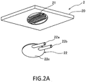
- FIG. 2A and FIG. 2B are drawings describing details of the cooler 2 of this embodiment and schematic perspective views when the cooler 2 is viewed from obliquely downward.
- FIG. 2A is a drawing describing components of the cooler 2.
- FIG. 2B is a drawing describing the configuration of the cooler 2 in a state where the respective components are combined with one another.
- the cooler 2 includes a plate-shaped main body 20, the coolant flow passage 21, and the coolant input/output portion 22.
- the coolant flow passage 21 is configured to circulate the coolant inside the main body 20. More specifically, the coolant flow passage 21 is formed such that the lower surface side of the main body 20 is open inside the main body 20.
- the coolant input/output portion 22 is joined to the lower surface of the main body 20 so as to cover the coolant flow passage 21 to allow the coolant to be held and flow inside the coolant flow passage 21.
- the coolant input/output portion 22 is joined to the lower surface of the main body 20 so as to cover at least the open part of the coolant flow passage 21 to form the coolant flow passage 21 that can hold and flow the coolant.
- the coolant input/output portion 22 includes the coolant introduction pipe 22a, the coolant discharge pipe 22b, and a supporting portion 22c.
- the coolant introduction pipe 22a introduces the coolant from outside the cooler 2 to the coolant flow passage 21.
- the coolant discharge pipe 22b discharges the coolant inside the coolant flow passage 21 to outside the cooler 2.
- the supporting portion 22c supports the coolant introduction pipe 22a and the coolant discharge pipe 22b. That is, the coolant input/output portion 22 is coupled to the coolant flow passage 21 and has a function to exchange the coolant between outside the cooler 2 and the coolant flow passage 21.
- FIG. 2B illustrates the cooler 2 in a state where the coolant input/output portion 22 is joined to the main body 20.
- the coolant input/output portion 22 of this embodiment is joined to the main body 20 such that at least a part of distal end portions of the coolant introduction pipe 22a and the coolant discharge pipe 22b project in a surface direction of the main body 20 (outside with respect to the side surface).
- the dotted line illustrated near an outer edge of the coolant input/output portion 22 in the drawing indicates a joined part between the coolant input/output portion 22 and the main body 20.
- hoses are mounted to the distal ends of the coolant introduction pipe 22a and the coolant discharge pipe 22b, and the coolant is exchanged between outside the cooler 2 and the coolant flow passage 21 via these hoses.
- the power converter 100 assuming the above-described configuration further includes the following features. That is, with the power converter 100 of this embodiment, a joining strength of the part (sealed portion) where the main body 20 and the coolant input/output portion 22 constituting the cooler 2 is joined together is configured lower than a strength of the main body 20.
- the sealed portions are joined by bolt fastening using a bolt made of a material having a strength lower than at least a strength of the metal forming the main body 20.
- the sealed portions are joined by joining technique, such as welding and brazing, in which the joining strength is configured to be lower than at least the strength of the metal forming the main body 20.
- the sealed portions are joined by bolt fastening using a bolt made of a material having a strength lower than at least a strength of the resin forming the main body 20.
- the sealed portions are joined by joining technique, such as welding, in which the joining strength is configured to be lower than at least the strength of the resin forming the main body 20.
- the joining is performed by bolt fastening using a bolt made of a material having a strength lower than at least a strength of the material forming the main body 20 or by joining technique, such as joining of different kinds of materials, in which the joining strength is configured to be lower than at least a strength of the material forming the main body 20. It should be noted that, formation of at least one of the main body 20 and the coolant input/output portion 22 with resin allows weight reduction and low cost compared with formation of these portions with metal.
- the coolant input/output portion 22 may have the strength configured lower than the joining strength of the sealed portions. In this case, when an external force is input to the coolant input/output portion 22, the coolant input/output portion 22 deforms to ensure reducing stress acting on the sealed portions.
- the joining strength of the joined part (sealed portion) with the main body 20 is configured lower than at least the strength of the main body 20.
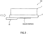
- FIG. 3 is a drawing describing the effects provided by the power converter 100 of the present embodiment.
- FIG. 3 is a schematic configuration diagram when the power converter 100 excluding the cover 3 is viewed from the side surface.
- the arrow in the drawing exemplifies a principal direction of the external force input to the power converter 100 during collision or the like.
- the external force acting on the illustrated direction is input to the coolant input/output portion 22 via a hose (not illustrated) or the like.
- the joining strength of the sealed portions is lower than the strength of the main body 20 in the power converter 100 of the present embodiment, the joining of the sealed portions is released against this external force before the main body 20 is damaged.
- the joining of the sealed portions is released in the case where the sealed portions are joined by bolt fastening, due to a breakage of the bolt, such as a fracture of the bolt.
- the joining of the sealed portions is released in the case where the sealed portions are joined by welding, deposition, or the like, due to a breakage of these joined parts caused by, for example, separation and peeling, the joining of the sealed portions is released.
- the parts (sealed portions) having the low strength is purposely configured in the power converter 100, thus determining the sealed portion as the broken part due to the external force. Consequently, when the external force is input to the coolant input/output portion 22, the coolant input/output portion 22 is displaced according to this external force. This allows reducing this external force reaching a part other than the sealed portion of the main body 20. As a result, damage of the main body 20 in the cooler 2 due to the external force can be avoided.
- the broken part due to the external force is determined to be the sealed portion. Therefore, a direction in which the coolant leaks can be limited to downward in the gravity direction (a direction to the lower surface side of the cooler 2). Therefore, a failure of the power converter circuit 1 caused by adhesion of leaked coolant to the power converter circuit 1, which is placed on the upper surface of the cooler 2, can be avoided. Further, when the external force acts on the power converter 100, the coolant input/output portion 22 is displaced according to this external force to ensure avoiding the influence from this external force to reach the power converter circuit 1 placed on the main body 20. Accordingly, a possibility of damage of the power converter circuit 1 due to this external force can be reduced.
- the in-car power converter 100 of the present embodiment includes the power converter circuit 1, the cooler 2, and the cover member 3.
- the power converter circuit 1 is configured to convert the input electric power into DC power or AC power.
- the power converter circuit 1 is placed on the cooler 2.
- the cooler 2 is configured to cool the power converter 1.
- the power converter circuit 1 is housed between the cooler 2 and the cover member 3.
- the cooler 2 includes the main body 20, the coolant flow passage 21, and the coolant input/output portion 22.
- the coolant flow passage 21 is formed inside the main body 20.
- the coolant is circulatable through the coolant flow passage 21.
- the coolant input/output portion 22 is coupled to the coolant flow passage 21.
- the coolant input/output portion 22 includes the coolant introduction pipe 22a and the coolant discharge pipe 22b.
- the coolant introduction pipe 22a introduces the coolant from outside the cooler 2.
- the coolant discharge pipe 22b discharges the coolant to outside the cooler 2.
- the coolant input/output portion 22 is joined to the main body 20.
- the joined part (sealed portions) has the joining strength lower than the strength of the main body 20.
- the in-car power converter 100 of the present embodiment includes the power converter circuit 1, the cooler 2, and the cover member 3.
- the power converter circuit 1 is configured to convert the input electric power into DC power or AC power.
- the power converter circuit 1 is placed on the cooler 2.
- the cooler 2 is configured to cool the power converter 1.
- the power converter circuit 1 is housed between the cooler 2 and the cover member 3.
- the cooler 2 includes the main body 20, the coolant flow passage 21, and the coolant input/output portion 22.
- the coolant flow passage 21 is formed inside the main body 20.
- the coolant is circulatable through the coolant flow passage 21.
- the coolant input/output portion 22 is coupled to the coolant flow passage 21.
- the coolant input/output portion 22 includes the coolant introduction pipe 22a and the coolant discharge pipe 22b.
- the coolant introduction pipe 22a introduces the coolant from outside the cooler 2.
- the coolant discharge pipe 22b discharges the coolant to outside the cooler 2.
- the coolant input/output portion 22 is joined to the main body 20. The joined parts (sealed portions) between the coolant input/output portion 22 and the main body 20 are broken prior to the main body 20 when the external force is input to the coolant input/output portion 22.
- the broken part due to this external force can be determined to be the sealed portion. Therefore, the displacement of the coolant input/output portion 22 according to this external force allows avoiding the main body of the cooler 2 to be damaged. Consequently, damage or a failure of the power converter circuit 1, which is placed on the upper surface of the cooler 2, due to the external force input to the power converter 100 can be avoided.
- the coolant input/output portion 22 is joined to the main body 20 such that at least the distal end portions of the coolant introduction pipe 22a and the coolant discharge pipe 22b project in the surface direction of the main body. This facilitates inputting the external force input from outside the cooler 2 to the coolant introduction pipe 22a and the coolant discharge pipe 22b prior to the main body 20, thereby further ensuring reducing a possibility of the external force acting on the main body 20.
- the power converter circuit 1 is placed on the upper surface of the main body 20.
- the coolant input/output portion 22 is joined to the lower surface of the main body 20. This allows limiting the direction in which the coolant leaks to downward in the gravity direction (the direction to the lower surface side of the cooler 2). Therefore, the adhesion of leaked coolant to the power converter circuit 1, which is placed on the upper surface of the cooler 2, can be avoided.
- At least one of the main body 20 and the coolant input/output portion 22 is made of resin. This formation allows weight reduction and low cost compared with the formation of the main body 20 and the coolant input/output portion 22 with metal.
- the following describes a power converter 200 of the second embodiment.
- the power converter 200 differs from that of the first embodiment in that a reinforcing member 5 is further provided.
- the reinforcing member 5 is configured as a member to reduce stress especially acting on the sealed portion when the external force is input to the coolant input/output portion 22.
- the following describes the reinforcing member 5.
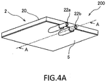
- FIG. 4 is a schematic configuration diagram describing the reinforcing member 5 of this embodiment.
- FIG. 4A is a perspective view when, in the power converter 200 including the reinforcing member 5, the cooler 2 and the reinforcing member 5 are viewed from obliquely downward.
- FIG. 4B is a cross-sectional view taken along A-A of the power converter 200 illustrated in FIG. 4A .
- the reinforcing member 5 of the present embodiment is a plate-shaped member.
- the reinforcing member 5 is configured so as to cover at least a part of the coolant input/output portion 22 on the lower surface of the cooler 2. More specifically, the reinforcing member 5 covers at least a part of respective coolant introduction pipe 22a and coolant discharge pipe 22b provided with the coolant input/output portion 22 on the lower surface of the cooler 2.
- the reinforcing member 5 of the present embodiment is fixed to the lower surface of the cooler 2 with a joining strength higher than at least joining strength of the sealed portions with a bolt (not illustrated) or the like.
- the reinforcing member 5 thus covering at least a part of the coolant input/output portion 22 ensures reducing the displacement of the coolant input/output portion 22 due to the external force when this external force acts on the coolant input/output portion 22.
- FIG. 4B is a cross-sectional view taken along A-A of the power converter 200 illustrated in FIG. 4A and a cross-sectional side view of the cooler 2 and the reinforcing member 5.
- the reinforcing member 5 of the present embodiment has a clearance (clearance A) having a predetermined width in a thickness direction of the cooler 2 (an up-down direction in the drawing) from lower surfaces of the coolant introduction pipe 22a and the coolant discharge pipe 22b of the coolant input/output portion 22.
- the reinforcing member 5 has a clearance (clearance B) having a predetermined width in the surface direction of the cooler 2 (the right-left direction in the drawing) from an end portion on an opposite side from an introduction port of the coolant introduction pipe 22a and a discharge port of the coolant discharge pipe 22b of the coolant input/output portion 22 in a principal input direction of the external force (the arrow direction in the drawing).
- the clearances A and B may be appropriately configured.
- configuring the clearance A allows restricting the displacement or the deformation of the coolant introduction pipe 22a and the coolant discharge pipe 22b mainly in the thickness direction when the external force is input to the coolant input/output portion with the clearance A.
- configuring the clearance B allows restricting the displacement of the coolant introduction pipe 22a and the coolant discharge pipe 22b mainly in the surface direction when the external force is input to the coolant input/output portion with the clearance B.
- the reinforcing member 5 allows reducing the displacement of the coolant input/output portion 22 caused by the external force within a predetermined range. Accordingly, a possibility of a breakage of the sealed portion can be reduced and durability of the entire cooler 2 can be improved.
- the strength of the cooler 2 can be configured to be lower than that of the conventional one, ensuring achieving low cost and reduction in size.
- the clearance A may be configured to be approximately 0 such that the reinforcing member 5 and the lower surface of the coolant input/output portion 22 nearly contact.
- the clearance B is not narrowed down like the clearance A but may be configured as follows. That is, as illustrated in FIG. 4B , the clearance B of the present embodiment may be configured to have a length where the displacement of the coolant input/output portion 22 in the principal input direction of the external force (the arrow direction in the drawing) when this external force is input to is not interfered.
- the clearance B of the reinforcing member 5 thus configured allows the displacement in the principal input direction of the external force while reducing the displacement of the coolant input/output portion 22 in the thickness direction of the cooler 2.
- the coolant input/output portion 22 is displaced in the surface direction of the cooler 2 according to this external force.
- the broken part due to the external force can be further accurately determined to be the sealed portion.
- the material of the reinforcing member 5 is not especially limited, a material, such as metal, having a strength higher than at least that of the coolant input/output portion 22 is preferred.
- the reinforcing member 5 of the present embodiment may be configured to double as a function (electromagnetic shielding function) that blocks an influence from an electromagnetic wave possibly generated in a vehicle to the power converter 200.
- the reinforcing member 5 may be made of a material having a conductive property and grounded to a vehicle body (electrically conducted to GND of the vehicle). This ensures improving the durability of the cooler 2 and configuring the power converter 200 including the reinforcing member 5 having the electromagnetic shielding function. This eliminates the need for separately preparing a member having an electromagnetic shielding function and allows configuring the power converter 200 having the electromagnetic shielding function at a price lower than the conventional one.
- the reinforcing member 5 may be made of a material at a low price further (for example, a press-worked thin walled metal plate). In that case, the reinforcing member 5 may be configured into the power converter 200 as a member independently having the electromagnetic shielding function, not the member to improve the durability of the cooler 2.
- the cooler 2 includes the reinforcing member 5.
- the reinforcing member 5 covers at least a part of the coolant input/output portion 22.
- the reinforcing member 5 is the plate-shaped member.
- the reinforcing member 5 has the conductive property and is grounded to the vehicle body. Accordingly, the reinforcing member 5 can double as the electromagnetic shielding function, thereby eliminating the need for separately preparing the member having the electromagnetic shielding function. Consequently, the power converter 200 having the electromagnetic shielding function can be configured at a price lower than the conventional one.
- the predetermined clearances (clearances A and B) are provided in the surface direction of the cooler 2 and the direction perpendicular to the surface direction.
- the reinforcing member 5 allows reducing the displacement of the coolant input/output portion 22 caused by the external force within the predetermined range (clearances A and B). Accordingly, a possibility of a breakage of the sealed portion can be reduced and durability of the entire cooler 2 can be improved.
- the following describes a power converter 300 of the third embodiment.
- the power converter 300 differs from that of the second embodiment in an aspect of the reinforcing member 5.
- the power converter 300 of the present embodiment features that a part of a motor housing 7 housing a motor 6 mounted to a vehicle is utilized as the reinforcing member 5, instead of the reinforcing member 5 as the plate-shaped member in the second embodiment.
- FIG. 5 to FIG. 8 are drawings describing the motor housing 7 utilized as the reinforcing member 5 in the power converter 300 of the present embodiment.
- FIG. 5 to FIG. 8 mainly illustrate the motor 6, the motor housing 7 housing the motor 6, and the cooler 2 disposed on the upper surface or above the motor housing 7.
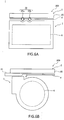
- FIG. 5A and FIG. 5B are drawings describing the aspect that the motor housing 7 doubles as the function of the reinforcing member 5 in the power converter 300.
- FIG. 5A is a front view when the power converter 300 is viewed from an axis direction of the motor 6.
- FIG. 5B is a side view when the power converter 300 is viewed from a direction perpendicular to the axis direction of the motor 6.
- a part of the lower surface of the cooler 2 especially at least a part of the lower surfaces of the coolant introduction pipe 22a and the coolant discharge pipe 22b of the coolant input/output portion 22 are disposed close to at least a part of an upper surface of the motor housing 7.
- the power converter 300 is configured such that a part of the motor housing 7 plays a role as the function of the reinforcing member 5. It should be noted that, the motor housing 7 having the conductive property may be grounded to the vehicle body to double as the electromagnetic shielding function similarly to the reinforcing member 5 of the second embodiment.
- a space for mounting the power converter 300 to the vehicle can be further decreased.
- the motor housing 7 doubling as the function of the reinforcing member 5 eliminates the need for separately disposing the reinforcing member as the plate-shaped member as in the second embodiment, ensuring achieving a low cost.
- a relative arrangement between the cooler 2 and the motor housing 7 and a shape of the upper surface of the motor housing 7 are preferably configured providing the predetermined clearance (clearance A) according to the shape of the lower surface of the coolant input/output portion 22 as illustrated in the drawings.
- the power converter 300 may separately include a plate-shaped member 8 covering a part other than the part covered by the motor housing 7 in the lower surface of the cooler 2.
- the motor housing 7 and the plate-shaped member 8 have the function of the reinforcing member 5 covering the entire lower surface of the cooler 2.
- FIG. 6A and FIG. 6B are drawings describing the aspect where the motor housing 7 doubles as the function of the reinforcing member 5 in the power converter 300 and illustrate an aspect where an arrangement of the cooler 2 relative to the motor housing 7 is rotated by 90 degrees in the surface direction compared with the arrangement of the cooler 2 illustrated in FIG. 5 .
- FIG. 6A is a side view when the power converter 300 is viewed from the direction perpendicular to the axis direction of the motor 6.
- FIG. 6B is a front view when the power converter 300 is viewed from the axis direction of the motor 6.
- a part of the motor housing 7 doubling as the function of the reinforcing member 5 allows disposing the power converter 300 close to the motor housing 7 further.
- the space for mounting the power converter 300 to the vehicle can be further decreased. That is, the relative arrangement between the cooler 2 and the motor housing 7 in the surface direction may be appropriately configured and is not specifically limited.
- FIG. 7A and FIG. 7B are drawings describing the aspect where the motor housing 7 doubles as the function of the reinforcing member 5 in the power converter 300.
- FIG. 7A is a side view when the power converter 300 is viewed from the direction perpendicular to the axis direction of the motor 6.
- FIG. 7B is a front view when the power converter 300 is viewed from the axis direction of the motor 6.
- the lower surface of the cooler 2 is disposed close to the upper surface of the motor housing 7. Accordingly, a part of the motor housing 7 can play a role as the function of the reinforcing member 5 covering the entire lower surface of the cooler 2.
- the motor housing 7 having the conductive property may be grounded to the vehicle body to double as the electromagnetic shielding function similarly to the configuration described above with reference to FIG. 5 .
- the power converter 300 and the motor housing 7 can be disposed to be close further, a space for mounting the power converter 300 to the vehicle can be further decreased.
- the motor housing 7 doubling as the function of the reinforcing member 5 eliminates the need for separately disposing the reinforcing member as the plate-shaped member as in the second embodiment, thus ensuring achieving cost reduction.
- a relative arrangement between the cooler 2 and the motor housing 7 and a shape of the upper surface of the motor housing 7 are preferably configured providing the predetermined clearances (the clearance A and the clearance B) from the shape of the lower surface of the cooler 2 as illustrated in the drawings.
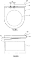
- FIG. 8A and FIG. 8B are drawings describing the aspect where the motor housing 7 doubles as the function of the reinforcing member 5 in the power converter 300 and illustrate an aspect where an arrangement of the cooler 2 relative to the motor housing 7 is rotated by 90 degrees in the surface direction compared with the arrangement of the cooler 2 illustrated in FIG. 7 .
- FIG. 8A is a front view when the power converter 300 is viewed from the axis direction of the motor 6.
- FIG. 8B is a side view when the power converter 300 is viewed from the direction perpendicular to the axis direction of the motor 6.
- cooler 2 and the motor housing 7 provided with the power converter 300 only need to maintain the above-described relative arrangement in the vehicle body, and the cooler 2 and the motor housing 7 are not necessary to be directly joined.
- the above-described relative arrangement can be achieved by, for example, fixing each of the cooler 2 and the motor housing 7 to a part of the vehicle body (not illustrated).
- the cooler 2 is disposed above the motor 6 provided with the vehicle and the reinforcing member 5 is a part of the motor housing 7 that houses the motor 6. Accordingly, regarding a layout of the vehicle body, since the power converter 300 and the motor housing 7 can be disposed to be close further, a space for mounting the power converter 300 to the vehicle can be further decreased.
- the motor housing 7 doubling as the function of the reinforcing member 5 eliminates the need for separately disposing the reinforcing member as the plate-shaped member as in the second embodiment, ensuring achieving a low cost further.
- the following describes a power converter 400 of the fourth embodiment.
- the power converter 400 especially features a material forming the cover 3 and provision of a rule on the relative arrangement between the cover 3 and the motor housing 7, in addition to the configuration of the power converter 300.
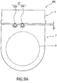
- FIG. 9A and FIG. 9B are drawings describing the function that the cover 3 and the motor housing 7 have in the power converter 400.
- FIG. 9A is a front view when the power converter 400 is viewed from the axis direction of the motor 6.
- FIG. 9B is a side view when the power converter 400 is viewed from the direction perpendicular to the axis direction of the motor 6.
- the cover 3 of the present embodiment has the conductive property and is grounded to the vehicle body.
- the motor housing 7 also has the conductive property and is grounded to the vehicle body.
- a predetermined clearance c is provided between the lower surface of the cover 3 and the upper surface of the motor housing 7.
- As the predetermined clearance c a length shorter than a wavelength of an electromagnetic wave possibly generated in the vehicle, that is, an electromagnetic wave possibly input to the power converter 400 is configured.
- the cover 3 and the motor housing 7 thus configured allow the cover 3 and the motor housing 7 to have the electromagnetic shielding function for the power converter circuit 1 housed inside. This eliminates the need for separately including a member having the electromagnetic shielding function. Therefore, while the power converter 400 has the electromagnetic shielding function, downsizing and low cost can be further achieved compared with the conventional one.
- the relative arrangement between the cover 3 and the motor housing 7 in the surface direction may be appropriately configured and is not specifically limited.
- the cover member 3 and the motor housing 6 have the conductive property and are grounded to the vehicle body.
- the clearance c shorter than the wavelength of the electromagnetic wave possibly generated in the vehicle is provided between the cover member 3 and the motor housing 7. This eliminates the need for separately including a member having the electromagnetic shielding function. Therefore, while the power converter 400 has the electromagnetic shielding function, downsizing and low cost can be further achieved compared with the conventional one.
- the method for joining the main body 20 and the coolant input/output portion 22 together is not limited to the exemplified methods. As long as assuming that the joining strength of the joined part (sealed portion) is lower than the strength of the main body 20, the joining method may be appropriately selected.
- the input of the external force to the coolant input/output portion 22 is not necessarily only the direct input to the coolant input/output portion 22 but also includes an indirect input via the hose or the like coupled to the coolant input/output portion 22. Additionally, the external force input to the coolant input/output portion 22 is not only caused by a collision or the like but includes a pressure or the like when the hose is coupled to the coolant input/output portion 22.
- the coolant introduction portion 22a and the coolant discharge portion 22b may be joined to the main body 20 without having the projecting parts in the surface direction of the main body 20.
- the coolant input/output portion 22 is not necessarily to be joined to the lower surface of the main body 20 but may be joined to the side surface or the upper surface of the main body 20.
- the coolant introduction portion 22a and the coolant discharge portion 22b are not necessarily to be integrally configured but may be configured as two separate members.
- the shape of the coolant input/output portion 22 illustrated in FIG. 2B may be, for example, an aspect as illustrated in FIG. 10 . That is, as illustrated in FIG. 10 , in the coolant input/output portion 22, the supporting portion 22c may cover the entire lower surface of the cooler 2. It should be noted that, in that case, the coolant input/output portion 22 may be joined to the lower surface of the cooler 2, for example, at the dotted line part illustrated in FIG. 10 . Further, the coolant input/output portion 22 illustrated in FIG. 10 made of metal or the like can double as the electromagnetic shielding function similarly to the reinforcing member 5.
Landscapes
- Engineering & Computer Science (AREA)
- Microelectronics & Electronic Packaging (AREA)
- Power Engineering (AREA)
- Physics & Mathematics (AREA)
- Thermal Sciences (AREA)
- Inverter Devices (AREA)
- Electric Propulsion And Braking For Vehicles (AREA)
- Dc-Dc Converters (AREA)
Abstract
Description
- The present invention relates to a power converter.
- In order to improve durability against an external force input to a coolant introduction pipe and a coolant discharge pipe to introduce coolant from outside or discharge the coolant in a cooler provided with a power converter,
JP2014-225938A - However, since the coolant introduction pipe and the coolant discharge pipe are fixed to the case using the coupling plate and the clamps in the above-described power converter, a space required to dispose the power converter in the case increases, thereby increasing a size of the entire case. Additionally, each of the coupling plate, the clamps, and the case need to have a strength enduring an external force. Therefore, expensive members having these strengths are required and this results in a cost increase.
- Further, the above-described power converter improves the durability by dispersing the external force input to the coolant introduction pipe and the coolant discharge pipe into the entire cooler including the case via, for example, the clamps. In view of this, in a case where the input external force is large, not only the coolant introduction pipe and the coolant discharge pipe but also the cooler main body is possibility damaged.
- An object of the present invention is to provide a technique that ensures avoiding a cooler main body to be damaged without a need for a member, such as a coupling plate and a clamp, even in a case where an external force input to a coolant introduction pipe and a coolant discharge pipe is large.
- A power converter according to one aspect of the present invention includes a power converter circuit, a cooler, and a cover member. The power converter circuit is configured to convert the input electric power into DC power or AC power. The power converter circuit is placed on the cooler. The cooler is configured to cool the power converter. The power converter circuit is housed between the cooler and the cover member. The cooler includes a main body, a coolant flow passage, and a coolant input/output portion. The coolant flow passage is formed inside the main body. A coolant is circulatable through the coolant flow passage. The coolant input/output portion is coupled to the coolant flow passage. The coolant input/output portion includes a coolant introduction pipe and a coolant discharge pipe. The coolant introduction pipe introduces the coolant from outside the cooler. The coolant discharge pipe discharges the coolant to outside the cooler. The coolant input/output portion is joined to the main body. The joined part has a joining strength lower than a strength of the main body.
- The following describes the embodiments of the present invention in detail with accompanying drawings.
-
-
FIG. 1 is a schematic configuration diagram describing an in-car power converter of a first embodiment. -
FIG. 2A is a drawing describing components of a cooler. -
FIG. 2B is a drawing describing a configuration of the cooler. -
FIG. 3 is a drawing describing effects provided by the power converter of the first embodiment. -
FIG. 4A is a perspective view when a cooler and a reinforcing member of a second embodiment are viewed from obliquely downward. -
FIG. 4B is a cross-sectional view taken along A-A of the power converter illustrated inFIG. 4A . -
FIG. 5A is a front view when a power converter of a third embodiment is viewed from an axis direction of a motor. -
FIG. 5B is a side view when the power converter of the third embodiment is viewed from a direction perpendicular to the axis direction of the motor. -
FIG. 6A is a side view when a power converter of another aspect of the third embodiment is viewed from the direction perpendicular to the axis direction of the motor. -
FIG. 6B is a front view when the power converter of another aspect of the third embodiment is viewed from the axis direction of the motor. -
FIG. 7A is a side view when a power converter of another aspect of the third embodiment is viewed from the direction perpendicular to the axis direction of the motor. -
FIG. 7B is a front view when the power converter of another aspect of the third embodiment is viewed from the axis direction of the motor. -
FIG. 8A is a front view when a power converter of another aspect of the third embodiment is viewed from the axis direction of the motor. -
FIG. 8B is a side view when the power converter of another aspect of the third embodiment is viewed from the direction perpendicular to the axis direction of the motor. -
FIG. 9A is a front view when a power converter of a fourth embodiment is viewed from the axis direction of the motor. -
FIG. 9B is a side view when the power converter of the fourth embodiment is viewed from the direction perpendicular to the axis direction of the motor. -
FIG. 10 is a drawing describing another aspect of a coolant input/output portion of the first embodiment. -
FIG. 1 is a schematic configuration diagram describing apower converter 100 of the first embodiment. - The
power converter 100 includes apower converter circuit 1, acooler 2, and acover 3. Thepower converter 100 is, for example, mounted to a vehicle including a motor and functions as an in-car power converter as electric power supply means for this motor. - The
power converter circuit 1 is an electric circuit, for example, an inverter that converts input electric power into predetermined electric power and outputs the predetermined electric power. Thepower converter circuit 1 is constituted of, for example, a semiconductor module and a smoothing capacitor. Thepower converter circuit 1 is electrically coupled to an external power supply via an electrical terminal (input terminal) (not illustrated) and coupled to the motor (not illustrated) via another electrical terminal (output terminal). Thepower converter circuit 1 converts DC power supplied from the above-described external power supply into AC power and supplies the AC power to the motor or converts AC power supplied from the motor into DC power and supplies the DC power to the external power supply. Further, thepower converter circuit 1 of this embodiment is placed on one surface (upper surface) of thecooler 2 and is fixed to thecooler 2 with, for example, a fixing bolt (not illustrated). - The
cooler 2 cools thepower converter circuit 1. Thecooler 2 includes a coolant flow passage 21 (seeFIG. 2 ) inside which coolant (such as cooling water) can be flowed. Thecooler 2 is heat-exchanged between the coolant flowing through thecoolant flow passage 21 and thepower converter circuit 1 to cool thepower converter circuit 1. Thecooler 2 includes acoolant introduction pipe 22a and acoolant discharge pipe 22b on its one surface (lower surface). Thecoolant introduction pipe 22a causes the coolant from outside thecooler 2 to run into thecoolant flow passage 21. Thecoolant discharge pipe 22b discharges the coolant inside thecoolant flow passage 21 to outside thecooler 2. Hereinafter, thecoolant introduction pipe 22a and thecoolant discharge pipe 22b are collectively referred to as "coolant input/output portion 22." Details of a configuration of thecooler 2 including the coolant input/output portion 22 will be described later with reference toFIG. 2 and the like. It should be noted that this Description designates a surface on a side where thepower converter circuit 1 is disposed of thecooler 2 as an upper surface (a surface on the upper side in the drawing) and a surface on a side where the coolant input/output portion 22 is disposed as a lower surface (a surface on the lower side in the drawing). - The
cover 3 functions as a housing that houses at least thepower converter circuit 1 disposed on thecooler 2. Thecover 3 of this embodiment has a depressed portion and is fixed to the upper surface of thecooler 2 using a fixing bolt (not illustrated) or the like such that thepower converter circuit 1 is housed in this depressed portion. That is, in thepower converter 100 of this embodiment, thecover 3 and thecooler 2 function as the housing that houses thepower converter circuit 1. That is, thecooler 2 may be configured to double as a function as a part of the housing that houses thepower converter circuit 1, in addition to the above-described cooling function. It should be noted that, thecover 3 may be configured to cover the lower surface side, not only the upper surface of thecooler 2. In this case, thecover 3 functions as the housing that houses both thepower converter circuit 1 and thecooler 2. Although not illustrated, thecover 3 has a hole portion to pass through a power line coupling thepower converter circuit 1 and the external power supply or the like in a state of being fixed to thecooler 2. -
FIG. 2A andFIG. 2B are drawings describing details of thecooler 2 of this embodiment and schematic perspective views when thecooler 2 is viewed from obliquely downward.FIG. 2A is a drawing describing components of thecooler 2.FIG. 2B is a drawing describing the configuration of thecooler 2 in a state where the respective components are combined with one another. - As illustrated in
FIG. 2A , thecooler 2 includes a plate-shapedmain body 20, thecoolant flow passage 21, and the coolant input/output portion 22. Thecoolant flow passage 21 is configured to circulate the coolant inside themain body 20. More specifically, thecoolant flow passage 21 is formed such that the lower surface side of themain body 20 is open inside themain body 20. The coolant input/output portion 22 is joined to the lower surface of themain body 20 so as to cover thecoolant flow passage 21 to allow the coolant to be held and flow inside thecoolant flow passage 21. In other words, the coolant input/output portion 22 is joined to the lower surface of themain body 20 so as to cover at least the open part of thecoolant flow passage 21 to form thecoolant flow passage 21 that can hold and flow the coolant. - Additionally, the coolant input/
output portion 22 includes thecoolant introduction pipe 22a, thecoolant discharge pipe 22b, and a supportingportion 22c. Thecoolant introduction pipe 22a introduces the coolant from outside thecooler 2 to thecoolant flow passage 21. Thecoolant discharge pipe 22b discharges the coolant inside thecoolant flow passage 21 to outside thecooler 2. The supportingportion 22c supports thecoolant introduction pipe 22a and thecoolant discharge pipe 22b. That is, the coolant input/output portion 22 is coupled to thecoolant flow passage 21 and has a function to exchange the coolant between outside thecooler 2 and thecoolant flow passage 21. -
FIG. 2B illustrates thecooler 2 in a state where the coolant input/output portion 22 is joined to themain body 20. The coolant input/output portion 22 of this embodiment is joined to themain body 20 such that at least a part of distal end portions of thecoolant introduction pipe 22a and thecoolant discharge pipe 22b project in a surface direction of the main body 20 (outside with respect to the side surface). The dotted line illustrated near an outer edge of the coolant input/output portion 22 in the drawing indicates a joined part between the coolant input/output portion 22 and themain body 20. It should be noted that, hereinafter, this joined part is referred to as "sealed portion." It should be noted that, although not illustrated, hoses are mounted to the distal ends of thecoolant introduction pipe 22a and thecoolant discharge pipe 22b, and the coolant is exchanged between outside thecooler 2 and thecoolant flow passage 21 via these hoses. - The
power converter 100 assuming the above-described configuration further includes the following features. That is, with thepower converter 100 of this embodiment, a joining strength of the part (sealed portion) where themain body 20 and the coolant input/output portion 22 constituting thecooler 2 is joined together is configured lower than a strength of themain body 20. - Specifically, for example, with the
main body 20 and the coolant input/output portion 22 made of metal, the sealed portions are joined by bolt fastening using a bolt made of a material having a strength lower than at least a strength of the metal forming themain body 20. Alternatively, instead of the bolt fastening, the sealed portions are joined by joining technique, such as welding and brazing, in which the joining strength is configured to be lower than at least the strength of the metal forming themain body 20. - Alternatively, with the
main body 20 and the coolant input/output portion 22 made of resin, the sealed portions are joined by bolt fastening using a bolt made of a material having a strength lower than at least a strength of the resin forming themain body 20. Alternatively, instead of the bolt fastening, the sealed portions are joined by joining technique, such as welding, in which the joining strength is configured to be lower than at least the strength of the resin forming themain body 20. - Alternatively, in a case where the
main body 20 and the coolant input/output portion 22 are made of different kinds of materials, such as themain body 20 being made of metal and the coolant input/output portion 22 being made of resin, the joining is performed by bolt fastening using a bolt made of a material having a strength lower than at least a strength of the material forming themain body 20 or by joining technique, such as joining of different kinds of materials, in which the joining strength is configured to be lower than at least a strength of the material forming themain body 20. It should be noted that, formation of at least one of themain body 20 and the coolant input/output portion 22 with resin allows weight reduction and low cost compared with formation of these portions with metal. The coolant input/output portion 22 may have the strength configured lower than the joining strength of the sealed portions. In this case, when an external force is input to the coolant input/output portion 22, the coolant input/output portion 22 deforms to ensure reducing stress acting on the sealed portions. - As exemplified above, in the coolant input/
output portion 22 of this embodiment, the joining strength of the joined part (sealed portion) with themain body 20 is configured lower than at least the strength of themain body 20. The following describes effects obtained by the coolant input/output portion 22 of this embodiment thus configured with reference toFIG. 3 . -
FIG. 3 is a drawing describing the effects provided by thepower converter 100 of the present embodiment.FIG. 3 is a schematic configuration diagram when thepower converter 100 excluding thecover 3 is viewed from the side surface. The arrow in the drawing exemplifies a principal direction of the external force input to thepower converter 100 during collision or the like. The external force acting on the illustrated direction is input to the coolant input/output portion 22 via a hose (not illustrated) or the like. - At this time, since the joining strength of the sealed portions is lower than the strength of the
main body 20 in thepower converter 100 of the present embodiment, the joining of the sealed portions is released against this external force before themain body 20 is damaged. For example, in the case where the sealed portions are joined by bolt fastening, due to a breakage of the bolt, such as a fracture of the bolt, the joining of the sealed portions is released. For example, in the case where the sealed portions are joined by welding, deposition, or the like, due to a breakage of these joined parts caused by, for example, separation and peeling, the joining of the sealed portions is released. - That is, in the present embodiment, the parts (sealed portions) having the low strength is purposely configured in the
power converter 100, thus determining the sealed portion as the broken part due to the external force. Consequently, when the external force is input to the coolant input/output portion 22, the coolant input/output portion 22 is displaced according to this external force. This allows reducing this external force reaching a part other than the sealed portion of themain body 20. As a result, damage of themain body 20 in the cooler 2 due to the external force can be avoided. - Additionally, even when the influence from the external force causes a leakage of the coolant in the
coolant flow passage 21, the broken part due to the external force is determined to be the sealed portion. Therefore, a direction in which the coolant leaks can be limited to downward in the gravity direction (a direction to the lower surface side of the cooler 2). Therefore, a failure of thepower converter circuit 1 caused by adhesion of leaked coolant to thepower converter circuit 1, which is placed on the upper surface of thecooler 2, can be avoided. Further, when the external force acts on thepower converter 100, the coolant input/output portion 22 is displaced according to this external force to ensure avoiding the influence from this external force to reach thepower converter circuit 1 placed on themain body 20. Accordingly, a possibility of damage of thepower converter circuit 1 due to this external force can be reduced. - As described above, the in-
car power converter 100 of the present embodiment includes thepower converter circuit 1, thecooler 2, and thecover member 3. Thepower converter circuit 1 is configured to convert the input electric power into DC power or AC power. Thepower converter circuit 1 is placed on thecooler 2. Thecooler 2 is configured to cool thepower converter 1. Thepower converter circuit 1 is housed between thecooler 2 and thecover member 3. Thecooler 2 includes themain body 20, thecoolant flow passage 21, and the coolant input/output portion 22. Thecoolant flow passage 21 is formed inside themain body 20. The coolant is circulatable through thecoolant flow passage 21. The coolant input/output portion 22 is coupled to thecoolant flow passage 21. The coolant input/output portion 22 includes thecoolant introduction pipe 22a and thecoolant discharge pipe 22b. Thecoolant introduction pipe 22a introduces the coolant from outside thecooler 2. Thecoolant discharge pipe 22b discharges the coolant to outside thecooler 2. The coolant input/output portion 22 is joined to themain body 20. The joined part (sealed portions) has the joining strength lower than the strength of themain body 20. - The in-
car power converter 100 of the present embodiment includes thepower converter circuit 1, thecooler 2, and thecover member 3. Thepower converter circuit 1 is configured to convert the input electric power into DC power or AC power. Thepower converter circuit 1 is placed on thecooler 2. Thecooler 2 is configured to cool thepower converter 1. Thepower converter circuit 1 is housed between thecooler 2 and thecover member 3. Thecooler 2 includes themain body 20, thecoolant flow passage 21, and the coolant input/output portion 22. Thecoolant flow passage 21 is formed inside themain body 20. The coolant is circulatable through thecoolant flow passage 21. The coolant input/output portion 22 is coupled to thecoolant flow passage 21. The coolant input/output portion 22 includes thecoolant introduction pipe 22a and thecoolant discharge pipe 22b. Thecoolant introduction pipe 22a introduces the coolant from outside thecooler 2. Thecoolant discharge pipe 22b discharges the coolant to outside thecooler 2. The coolant input/output portion 22 is joined to themain body 20. The joined parts (sealed portions) between the coolant input/output portion 22 and themain body 20 are broken prior to themain body 20 when the external force is input to the coolant input/output portion 22. - Accordingly, when the external force is input to the
power converter 100, the broken part due to this external force can be determined to be the sealed portion. Therefore, the displacement of the coolant input/output portion 22 according to this external force allows avoiding the main body of thecooler 2 to be damaged. Consequently, damage or a failure of thepower converter circuit 1, which is placed on the upper surface of thecooler 2, due to the external force input to thepower converter 100 can be avoided. - Additionally, with the
power converter 100 of the first embodiment, the coolant input/output portion 22 is joined to themain body 20 such that at least the distal end portions of thecoolant introduction pipe 22a and thecoolant discharge pipe 22b project in the surface direction of the main body. This facilitates inputting the external force input from outside thecooler 2 to thecoolant introduction pipe 22a and thecoolant discharge pipe 22b prior to themain body 20, thereby further ensuring reducing a possibility of the external force acting on themain body 20. - With the
power converter 100 of the first embodiment, thepower converter circuit 1 is placed on the upper surface of themain body 20. The coolant input/output portion 22 is joined to the lower surface of themain body 20. This allows limiting the direction in which the coolant leaks to downward in the gravity direction (the direction to the lower surface side of the cooler 2). Therefore, the adhesion of leaked coolant to thepower converter circuit 1, which is placed on the upper surface of thecooler 2, can be avoided. - With the
power converter 100 of the first embodiment, at least one of themain body 20 and the coolant input/output portion 22 is made of resin. This formation allows weight reduction and low cost compared with the formation of themain body 20 and the coolant input/output portion 22 with metal. - The following describes a
power converter 200 of the second embodiment. Thepower converter 200 differs from that of the first embodiment in that a reinforcingmember 5 is further provided. The reinforcingmember 5 is configured as a member to reduce stress especially acting on the sealed portion when the external force is input to the coolant input/output portion 22. The following describes the reinforcingmember 5. -
FIG. 4 is a schematic configuration diagram describing the reinforcingmember 5 of this embodiment.FIG. 4A is a perspective view when, in thepower converter 200 including the reinforcingmember 5, thecooler 2 and the reinforcingmember 5 are viewed from obliquely downward.FIG. 4B is a cross-sectional view taken along A-A of thepower converter 200 illustrated inFIG. 4A . - As illustrated in
FIG. 4A , the reinforcingmember 5 of the present embodiment is a plate-shaped member. The reinforcingmember 5 is configured so as to cover at least a part of the coolant input/output portion 22 on the lower surface of thecooler 2. More specifically, the reinforcingmember 5 covers at least a part of respectivecoolant introduction pipe 22a andcoolant discharge pipe 22b provided with the coolant input/output portion 22 on the lower surface of thecooler 2. The reinforcingmember 5 of the present embodiment is fixed to the lower surface of thecooler 2 with a joining strength higher than at least joining strength of the sealed portions with a bolt (not illustrated) or the like. The reinforcingmember 5 thus covering at least a part of the coolant input/output portion 22 ensures reducing the displacement of the coolant input/output portion 22 due to the external force when this external force acts on the coolant input/output portion 22. -
FIG. 4B is a cross-sectional view taken along A-A of thepower converter 200 illustrated inFIG. 4A and a cross-sectional side view of thecooler 2 and the reinforcingmember 5. As illustrated inFIG. 4B , the reinforcingmember 5 of the present embodiment has a clearance (clearance A) having a predetermined width in a thickness direction of the cooler 2 (an up-down direction in the drawing) from lower surfaces of thecoolant introduction pipe 22a and thecoolant discharge pipe 22b of the coolant input/output portion 22. Additionally, the reinforcingmember 5 has a clearance (clearance B) having a predetermined width in the surface direction of the cooler 2 (the right-left direction in the drawing) from an end portion on an opposite side from an introduction port of thecoolant introduction pipe 22a and a discharge port of thecoolant discharge pipe 22b of the coolant input/output portion 22 in a principal input direction of the external force (the arrow direction in the drawing). - The clearances A and B may be appropriately configured. In the present embodiment, configuring the clearance A allows restricting the displacement or the deformation of the
coolant introduction pipe 22a and thecoolant discharge pipe 22b mainly in the thickness direction when the external force is input to the coolant input/output portion with the clearance A. Moreover, configuring the clearance B allows restricting the displacement of thecoolant introduction pipe 22a and thecoolant discharge pipe 22b mainly in the surface direction when the external force is input to the coolant input/output portion with the clearance B. Thus, the reinforcingmember 5 allows reducing the displacement of the coolant input/output portion 22 caused by the external force within a predetermined range. Accordingly, a possibility of a breakage of the sealed portion can be reduced and durability of theentire cooler 2 can be improved. As a result, the strength of thecooler 2 can be configured to be lower than that of the conventional one, ensuring achieving low cost and reduction in size. It should be noted that, the clearance A may be configured to be approximately 0 such that the reinforcingmember 5 and the lower surface of the coolant input/output portion 22 nearly contact. - Meanwhile, the clearance B is not narrowed down like the clearance A but may be configured as follows. That is, as illustrated in
FIG. 4B , the clearance B of the present embodiment may be configured to have a length where the displacement of the coolant input/output portion 22 in the principal input direction of the external force (the arrow direction in the drawing) when this external force is input to is not interfered. The clearance B of the reinforcingmember 5 thus configured allows the displacement in the principal input direction of the external force while reducing the displacement of the coolant input/output portion 22 in the thickness direction of thecooler 2. Thus, when the external force is input to the coolant input/output portion 22, the coolant input/output portion 22 is displaced in the surface direction of thecooler 2 according to this external force. Therefore, the broken part due to the external force can be further accurately determined to be the sealed portion. It should be noted that, while the material of the reinforcingmember 5 is not especially limited, a material, such as metal, having a strength higher than at least that of the coolant input/output portion 22 is preferred. - Additionally, the reinforcing
member 5 of the present embodiment may be configured to double as a function (electromagnetic shielding function) that blocks an influence from an electromagnetic wave possibly generated in a vehicle to thepower converter 200. Specifically, the reinforcingmember 5 may be made of a material having a conductive property and grounded to a vehicle body (electrically conducted to GND of the vehicle). This ensures improving the durability of thecooler 2 and configuring thepower converter 200 including the reinforcingmember 5 having the electromagnetic shielding function. This eliminates the need for separately preparing a member having an electromagnetic shielding function and allows configuring thepower converter 200 having the electromagnetic shielding function at a price lower than the conventional one. It should be noted that, without taking the improvement of the durability of thecooler 2 into consideration, the reinforcingmember 5 may be made of a material at a low price further (for example, a press-worked thin walled metal plate). In that case, the reinforcingmember 5 may be configured into thepower converter 200 as a member independently having the electromagnetic shielding function, not the member to improve the durability of thecooler 2. - As described above, with the
power converter 200 of the second embodiment, thecooler 2 includes the reinforcingmember 5. The reinforcingmember 5 covers at least a part of the coolant input/output portion 22. The reinforcingmember 5 is the plate-shaped member. Thus, the displacement of the coolant input/output portion 22 against the external force input to the coolant input/output portion 22 can be reduced and a possibility of a breakage of the sealed portion can be reduced. As a result, the durability of theentire cooler 2 can be improved. - With the
power converter 200 of the second embodiment, the reinforcingmember 5 has the conductive property and is grounded to the vehicle body. Accordingly, the reinforcingmember 5 can double as the electromagnetic shielding function, thereby eliminating the need for separately preparing the member having the electromagnetic shielding function. Consequently, thepower converter 200 having the electromagnetic shielding function can be configured at a price lower than the conventional one. - With the
power converter 200 of the second embodiment, between the coolant input/output portion 22 and the reinforcingmember 5, the predetermined clearances (clearances A and B) are provided in the surface direction of thecooler 2 and the direction perpendicular to the surface direction. Thus, the reinforcingmember 5 allows reducing the displacement of the coolant input/output portion 22 caused by the external force within the predetermined range (clearances A and B). Accordingly, a possibility of a breakage of the sealed portion can be reduced and durability of theentire cooler 2 can be improved. - The following describes a
power converter 300 of the third embodiment. Thepower converter 300 differs from that of the second embodiment in an aspect of the reinforcingmember 5. Thepower converter 300 of the present embodiment features that a part of amotor housing 7 housing amotor 6 mounted to a vehicle is utilized as the reinforcingmember 5, instead of the reinforcingmember 5 as the plate-shaped member in the second embodiment. -
FIG. 5 to FIG. 8 are drawings describing themotor housing 7 utilized as the reinforcingmember 5 in thepower converter 300 of the present embodiment.FIG. 5 to FIG. 8 mainly illustrate themotor 6, themotor housing 7 housing themotor 6, and thecooler 2 disposed on the upper surface or above themotor housing 7. -
FIG. 5A and FIG. 5B are drawings describing the aspect that themotor housing 7 doubles as the function of the reinforcingmember 5 in thepower converter 300.FIG. 5A is a front view when thepower converter 300 is viewed from an axis direction of themotor 6.FIG. 5B is a side view when thepower converter 300 is viewed from a direction perpendicular to the axis direction of themotor 6. As illustrated in the drawings, in thepower converter 300, a part of the lower surface of thecooler 2, especially at least a part of the lower surfaces of thecoolant introduction pipe 22a and thecoolant discharge pipe 22b of the coolant input/output portion 22 are disposed close to at least a part of an upper surface of themotor housing 7. Thus, thepower converter 300 is configured such that a part of themotor housing 7 plays a role as the function of the reinforcingmember 5. It should be noted that, themotor housing 7 having the conductive property may be grounded to the vehicle body to double as the electromagnetic shielding function similarly to the reinforcingmember 5 of the second embodiment. - Accordingly, regarding a layout of the vehicle body, since the
power converter 300 and themotor housing 7 can be disposed to be close further, a space for mounting thepower converter 300 to the vehicle can be further decreased. Themotor housing 7 doubling as the function of the reinforcingmember 5 eliminates the need for separately disposing the reinforcing member as the plate-shaped member as in the second embodiment, ensuring achieving a low cost. It should be noted that, a relative arrangement between thecooler 2 and themotor housing 7 and a shape of the upper surface of themotor housing 7 are preferably configured providing the predetermined clearance (clearance A) according to the shape of the lower surface of the coolant input/output portion 22 as illustrated in the drawings. As illustrated in the drawings, thepower converter 300 may separately include a plate-shapedmember 8 covering a part other than the part covered by themotor housing 7 in the lower surface of thecooler 2. In this case, themotor housing 7 and the plate-shapedmember 8 have the function of the reinforcingmember 5 covering the entire lower surface of thecooler 2. -
FIG. 6A and FIG. 6B are drawings describing the aspect where themotor housing 7 doubles as the function of the reinforcingmember 5 in thepower converter 300 and illustrate an aspect where an arrangement of thecooler 2 relative to themotor housing 7 is rotated by 90 degrees in the surface direction compared with the arrangement of thecooler 2 illustrated inFIG. 5 .FIG. 6A is a side view when thepower converter 300 is viewed from the direction perpendicular to the axis direction of themotor 6.FIG. 6B is a front view when thepower converter 300 is viewed from the axis direction of themotor 6. With the aspect illustrated inFIG. 6 as well, similarly to the aspect described above with reference toFIG. 5 , a part of themotor housing 7 doubling as the function of the reinforcingmember 5 allows disposing thepower converter 300 close to themotor housing 7 further. Thus, the space for mounting thepower converter 300 to the vehicle can be further decreased. That is, the relative arrangement between thecooler 2 and themotor housing 7 in the surface direction may be appropriately configured and is not specifically limited. -
FIG. 7A and FIG. 7B are drawings describing the aspect where themotor housing 7 doubles as the function of the reinforcingmember 5 in thepower converter 300.FIG. 7A is a side view when thepower converter 300 is viewed from the direction perpendicular to the axis direction of themotor 6.FIG. 7B is a front view when thepower converter 300 is viewed from the axis direction of themotor 6. As illustrated in the drawings, with thepower converter 300, the lower surface of thecooler 2 is disposed close to the upper surface of themotor housing 7. Accordingly, a part of themotor housing 7 can play a role as the function of the reinforcingmember 5 covering the entire lower surface of thecooler 2. It should be noted that, themotor housing 7 having the conductive property may be grounded to the vehicle body to double as the electromagnetic shielding function similarly to the configuration described above with reference toFIG. 5 . - Accordingly, since the
power converter 300 and themotor housing 7 can be disposed to be close further, a space for mounting thepower converter 300 to the vehicle can be further decreased. Themotor housing 7 doubling as the function of the reinforcingmember 5 eliminates the need for separately disposing the reinforcing member as the plate-shaped member as in the second embodiment, thus ensuring achieving cost reduction. It should be noted that, a relative arrangement between thecooler 2 and themotor housing 7 and a shape of the upper surface of themotor housing 7 are preferably configured providing the predetermined clearances (the clearance A and the clearance B) from the shape of the lower surface of thecooler 2 as illustrated in the drawings. -
FIG. 8A and FIG. 8B are drawings describing the aspect where themotor housing 7 doubles as the function of the reinforcingmember 5 in thepower converter 300 and illustrate an aspect where an arrangement of thecooler 2 relative to themotor housing 7 is rotated by 90 degrees in the surface direction compared with the arrangement of thecooler 2 illustrated inFIG. 7 .FIG. 8A is a front view when thepower converter 300 is viewed from the axis direction of themotor 6.FIG. 8B is a side view when thepower converter 300 is viewed from the direction perpendicular to the axis direction of themotor 6. With the aspect illustrated inFIG. 8 as well, similar to the aspect described above with reference toFIG. 7 , a part of themotor housing 7 doubling as the function of the reinforcingmember 5 allows disposing thepower converter 300 close to themotor housing 7 further. Thus, the space for mounting thepower converter 300 to the vehicle can be further decreased. - It should be noted that, the
cooler 2 and themotor housing 7 provided with thepower converter 300 only need to maintain the above-described relative arrangement in the vehicle body, and thecooler 2 and themotor housing 7 are not necessary to be directly joined. The above-described relative arrangement can be achieved by, for example, fixing each of thecooler 2 and themotor housing 7 to a part of the vehicle body (not illustrated). - As described above, with the
power converter 300 of the third embodiment, thecooler 2 is disposed above themotor 6 provided with the vehicle and the reinforcingmember 5 is a part of themotor housing 7 that houses themotor 6. Accordingly, regarding a layout of the vehicle body, since thepower converter 300 and themotor housing 7 can be disposed to be close further, a space for mounting thepower converter 300 to the vehicle can be further decreased. Themotor housing 7 doubling as the function of the reinforcingmember 5 eliminates the need for separately disposing the reinforcing member as the plate-shaped member as in the second embodiment, ensuring achieving a low cost further. - The following describes a
power converter 400 of the fourth embodiment. Thepower converter 400 especially features a material forming thecover 3 and provision of a rule on the relative arrangement between thecover 3 and themotor housing 7, in addition to the configuration of thepower converter 300. -
FIG. 9A andFIG. 9B are drawings describing the function that thecover 3 and themotor housing 7 have in thepower converter 400.FIG. 9A is a front view when thepower converter 400 is viewed from the axis direction of themotor 6.FIG. 9B is a side view when thepower converter 400 is viewed from the direction perpendicular to the axis direction of themotor 6. - The
cover 3 of the present embodiment has the conductive property and is grounded to the vehicle body. Themotor housing 7 also has the conductive property and is grounded to the vehicle body. A predetermined clearance c is provided between the lower surface of thecover 3 and the upper surface of themotor housing 7. As the predetermined clearance c, a length shorter than a wavelength of an electromagnetic wave possibly generated in the vehicle, that is, an electromagnetic wave possibly input to thepower converter 400 is configured. Thecover 3 and themotor housing 7 thus configured allow thecover 3 and themotor housing 7 to have the electromagnetic shielding function for thepower converter circuit 1 housed inside. This eliminates the need for separately including a member having the electromagnetic shielding function. Therefore, while thepower converter 400 has the electromagnetic shielding function, downsizing and low cost can be further achieved compared with the conventional one. It should be noted that the relative arrangement between thecover 3 and themotor housing 7 in the surface direction may be appropriately configured and is not specifically limited. - As described above, with the
power converter 400 of the fourth embodiment, thecover member 3 and themotor housing 6 have the conductive property and are grounded to the vehicle body. The clearance c shorter than the wavelength of the electromagnetic wave possibly generated in the vehicle is provided between thecover member 3 and themotor housing 7. This eliminates the need for separately including a member having the electromagnetic shielding function. Therefore, while thepower converter 400 has the electromagnetic shielding function, downsizing and low cost can be further achieved compared with the conventional one. - While the embodiments of the present invention and their modifications have been described, the embodiments and the modifications merely describe some application examples of the present invention and not a gist to limit the technical scope of the present invention to the specific configurations of the above embodiments. The above-described embodiments and their modifications can be combined appropriately within a scope not causing inconsistency.
- For example, the method for joining the
main body 20 and the coolant input/output portion 22 together is not limited to the exemplified methods. As long as assuming that the joining strength of the joined part (sealed portion) is lower than the strength of themain body 20, the joining method may be appropriately selected. - Moreover, the input of the external force to the coolant input/
output portion 22 is not necessarily only the direct input to the coolant input/output portion 22 but also includes an indirect input via the hose or the like coupled to the coolant input/output portion 22. Additionally, the external force input to the coolant input/output portion 22 is not only caused by a collision or the like but includes a pressure or the like when the hose is coupled to the coolant input/output portion 22. - It should be noted that, the illustrated drawings in this description are merely the schematic diagrams. Accordingly, the configurations illustrated in the drawings are one example. As long as meeting the matters defined in the above-described description, the configurations and the aspects are not limited to those illustrated in the drawings. For example, the
coolant introduction portion 22a and thecoolant discharge portion 22b may be joined to themain body 20 without having the projecting parts in the surface direction of themain body 20. The coolant input/output portion 22 is not necessarily to be joined to the lower surface of themain body 20 but may be joined to the side surface or the upper surface of themain body 20. In the coolant input/output portion 22, thecoolant introduction portion 22a and thecoolant discharge portion 22b are not necessarily to be integrally configured but may be configured as two separate members. - The shape of the coolant input/
output portion 22 illustrated inFIG. 2B may be, for example, an aspect as illustrated inFIG. 10 . That is, as illustrated inFIG. 10 , in the coolant input/output portion 22, the supportingportion 22c may cover the entire lower surface of thecooler 2. It should be noted that, in that case, the coolant input/output portion 22 may be joined to the lower surface of thecooler 2, for example, at the dotted line part illustrated inFIG. 10 . Further, the coolant input/output portion 22 illustrated inFIG. 10 made of metal or the like can double as the electromagnetic shielding function similarly to the reinforcingmember 5.
Claims (11)
- A power converter comprising:a power converter circuit configured to convert input electric power into DC power or AC power;a cooler on which the power converter circuit is placed to cool the power converter; anda cover member that houses the power converter circuit between the cooler and the cover member, whereinthe cooler includes:a main body;a coolant flow passage formed inside the main body, a coolant being circulatable through the coolant flow passage; anda coolant input/output portion coupled to the coolant flow passage, the coolant input/output portion including a coolant introduction pipe and a coolant discharge pipe, the coolant introduction pipe introducing the coolant from outside the cooler, the coolant discharge pipe discharging the coolant to outside the cooler, andthe coolant input/output portion is joined to the main body, the joined part having a joining strength lower than a strength of the main body.
- A power converter comprising:a power converter circuit configured to convert input electric power into DC power or AC power;a cooler on which the power converter circuit is placed to cool the power converter; anda cover member that houses the power converter circuit between the cooler and the cover member, whereinthe cooler includes:a main body;a coolant flow passage formed inside the main body, a coolant being circulatable through the coolant flow passage; anda coolant input/output portion coupled to the coolant flow passage, the coolant input/output portion including a coolant introduction pipe and a coolant discharge pipe, the coolant introduction pipe introducing the coolant from outside the cooler, the coolant discharge pipe discharging the coolant to outside the cooler, andthe coolant input/output portion is joined to the main body, the joined part between the coolant input/output portion and the main body being broken prior to the main body when an external force is input to the coolant input/output portion.
- The power converter according to claim 1 or claim 2, wherein
the coolant input/output portion is joined to the main body such that at least distal end portions of the coolant introduction pipe and the coolant discharge pipe project in a surface direction of the main body. - The power converter according to any one of claim 1 to claim 3, wherein
the power converter circuit is placed on an upper surface of the main body, and
the coolant input/output portion is joined to a lower surface of the main body. - The power converter according to any one of claim 1 to claim 4, wherein
at least one of the main body and the coolant input/output portion is made of resin. - The power converter according to any one of claim 1 to claim 5, wherein
the cooler includes a reinforcing member, the reinforcing member covering at least a part of the coolant input/output portion. - The power converter according to claim 6, wherein
the reinforcing member is a plate-shaped member. - The power converter according to claim 6, wherein
the cooler is disposed above a motor provided with a vehicle, and
the reinforcing member is a part of a motor housing that houses the motor. - The power converter according to any one of claim 6 to claim 8, wherein
the reinforcing member has a conductive property and is grounded to a vehicle body. - The power converter according to any one of claim 6 to claim 9, wherein
predetermined clearances are provided between the coolant input/output portion and the reinforcing member in a surface direction of the cooler and a direction perpendicular to the surface direction. - The power converter according to claim 8, wherein
the cover member and the motor housing have a conductive property and are grounded to a vehicle body, a clearance shorter than a wavelength of an electromagnetic wave possibly generated in the vehicle is provided between the cover member and the motor housing.
Applications Claiming Priority (1)
| Application Number | Priority Date | Filing Date | Title |
|---|---|---|---|
| PCT/JP2018/009692 WO2019175958A1 (en) | 2018-03-13 | 2018-03-13 | Electric power converter |
Publications (3)
| Publication Number | Publication Date |
|---|---|
| EP3767813A1 true EP3767813A1 (en) | 2021-01-20 |
| EP3767813A4 EP3767813A4 (en) | 2021-03-10 |
| EP3767813B1 EP3767813B1 (en) | 2024-08-07 |
Family
ID=67906543
Family Applications (1)
| Application Number | Title | Priority Date | Filing Date |
|---|---|---|---|
| EP18909648.0A Active EP3767813B1 (en) | 2018-03-13 | 2018-03-13 | Electric power converter |
Country Status (5)
| Country | Link |
|---|---|
| US (1) | US11516949B2 (en) |
| EP (1) | EP3767813B1 (en) |
| JP (1) | JP7067611B2 (en) |
| CN (1) | CN111954974B (en) |
| WO (1) | WO2019175958A1 (en) |
Family Cites Families (44)
| Publication number | Priority date | Publication date | Assignee | Title |
|---|---|---|---|---|
| US2450170A (en) * | 1946-11-15 | 1948-09-28 | Robert L Kahn | Fitting |
| US3659877A (en) * | 1970-09-11 | 1972-05-02 | Shell Oil Co | Breakaway pipe coupling |
| US4022497A (en) * | 1976-01-09 | 1977-05-10 | Imperial-Eastman Corporation | One-piece nut and sleeve for improved tube fitting |
| US4833567A (en) * | 1986-05-30 | 1989-05-23 | Digital Equipment Corporation | Integral heat pipe module |
| US4917149A (en) * | 1988-04-14 | 1990-04-17 | Dayco Products, Inc. | Breakaway coupling, conduit system utilizing the coupling and methods of making the same |
| US5023695A (en) * | 1988-05-09 | 1991-06-11 | Nec Corporation | Flat cooling structure of integrated circuit |
| US4975766A (en) * | 1988-08-26 | 1990-12-04 | Nec Corporation | Structure for temperature detection in a package |
| US4944534A (en) * | 1988-10-03 | 1990-07-31 | Mcneil (Ohio) Corporation | Frangible male coupling component |
| JPH06104358A (en) * | 1992-09-04 | 1994-04-15 | Hitachi Ltd | Electronic device cooled by liquid |
| US5316075A (en) * | 1992-12-22 | 1994-05-31 | Hughes Aircraft Company | Liquid jet cold plate for impingement cooling |
| US5448108A (en) * | 1993-11-02 | 1995-09-05 | Hughes Aircraft Company | Cooling of semiconductor power modules by flushing with dielectric liquid |
| US6367543B1 (en) * | 2000-12-11 | 2002-04-09 | Thermal Corp. | Liquid-cooled heat sink with thermal jacket |
| US6550263B2 (en) * | 2001-02-22 | 2003-04-22 | Hp Development Company L.L.P. | Spray cooling system for a device |
| US6679315B2 (en) * | 2002-01-14 | 2004-01-20 | Marconi Communications, Inc. | Small scale chip cooler assembly |
| US6994151B2 (en) * | 2002-10-22 | 2006-02-07 | Cooligy, Inc. | Vapor escape microchannel heat exchanger |
| US6754076B2 (en) * | 2002-10-30 | 2004-06-22 | International Business Machines Corporation | Stackable liquid cooling pump |
| US6986382B2 (en) * | 2002-11-01 | 2006-01-17 | Cooligy Inc. | Interwoven manifolds for pressure drop reduction in microchannel heat exchangers |
| US20050111188A1 (en) * | 2003-11-26 | 2005-05-26 | Anandaroop Bhattacharya | Thermal management device for an integrated circuit |
| US7380409B2 (en) * | 2004-09-30 | 2008-06-03 | International Business Machines Corporation | Isolation valve and coolant connect/disconnect assemblies and methods of fabrication for interfacing a liquid cooled electronics subsystem and an electronics housing |
| US7562444B2 (en) * | 2005-09-08 | 2009-07-21 | Delphi Technologies, Inc. | Method for manufacturing a CPU cooling assembly |
| US7272006B2 (en) * | 2005-09-30 | 2007-09-18 | Intel Corporation | IC coolant microchannel assembly with integrated attachment hardware |
| US7849914B2 (en) * | 2006-05-02 | 2010-12-14 | Clockspeed, Inc. | Cooling apparatus for microelectronic devices |
| US20080093054A1 (en) * | 2006-08-29 | 2008-04-24 | Tilton Charles L | Manifold for a Two-Phase Cooling System |
| US20110079376A1 (en) * | 2009-10-03 | 2011-04-07 | Wolverine Tube, Inc. | Cold plate with pins |
| JP5678490B2 (en) * | 2010-06-30 | 2015-03-04 | 株式会社デンソー | Power converter |
| JP5370297B2 (en) * | 2010-07-14 | 2013-12-18 | 株式会社デンソー | Power converter |
| JP5425029B2 (en) | 2010-09-15 | 2014-02-26 | アイシン・エィ・ダブリュ株式会社 | Semiconductor cooling device and vehicle drive device |
| JP2012139708A (en) * | 2010-12-28 | 2012-07-26 | Daikin Industries Ltd | Joint structure for metallic pipes |
| JP5423998B2 (en) * | 2011-08-31 | 2014-02-19 | 株式会社安川電機 | Electronic component cooling unit and power conversion device |
| US8934250B2 (en) * | 2012-09-26 | 2015-01-13 | International Business Machines Corporation | Immersion-cooling of selected electronic component(s) mounted to printed circuit board |
| JP6107400B2 (en) | 2013-05-15 | 2017-04-05 | 株式会社デンソー | Power converter |
| JP5880491B2 (en) * | 2013-07-01 | 2016-03-09 | トヨタ自動車株式会社 | Inverter case |
| JP6164304B2 (en) * | 2013-11-28 | 2017-07-19 | 富士電機株式会社 | Manufacturing method of semiconductor module cooler, semiconductor module cooler, semiconductor module, and electrically driven vehicle |
| JP5862646B2 (en) * | 2013-12-04 | 2016-02-16 | トヨタ自動車株式会社 | Refrigerant tube connection structure and inverter with built-in cooler |
| JP5991345B2 (en) * | 2013-12-26 | 2016-09-14 | 株式会社デンソー | Power converter |
| JP2015149825A (en) * | 2014-02-06 | 2015-08-20 | トヨタ自動車株式会社 | Laminated cooling unit |
| JP6237312B2 (en) * | 2014-02-17 | 2017-11-29 | 株式会社デンソー | Power converter |
| JP6331866B2 (en) * | 2014-08-18 | 2018-05-30 | 株式会社デンソー | Power converter |
| EP3195711A4 (en) * | 2014-09-15 | 2018-08-29 | D'Onofrio, Nicholas, Michael | Liquid cooled metal core printed circuit board |
| EP3295777A4 (en) * | 2015-05-15 | 2019-01-23 | Wolverine Tube, Inc. | Liquid cooled coldplate |
| JP6296027B2 (en) * | 2015-09-04 | 2018-03-20 | トヨタ自動車株式会社 | Refrigerant passage connection structure |
| JP6578917B2 (en) * | 2015-12-04 | 2019-09-25 | 株式会社デンソー | Power converter |
| JP6447480B2 (en) * | 2015-12-11 | 2019-01-09 | トヨタ自動車株式会社 | Sealing structure |
| JP6304270B2 (en) * | 2016-01-29 | 2018-04-04 | トヨタ自動車株式会社 | Control unit mounting structure |
-
2018
- 2018-03-13 CN CN201880091105.9A patent/CN111954974B/en active Active
- 2018-03-13 EP EP18909648.0A patent/EP3767813B1/en active Active
- 2018-03-13 WO PCT/JP2018/009692 patent/WO2019175958A1/en not_active Ceased
- 2018-03-13 US US16/980,260 patent/US11516949B2/en active Active
- 2018-03-13 JP JP2020505978A patent/JP7067611B2/en active Active
Also Published As
| Publication number | Publication date |
|---|---|
| US20210029851A1 (en) | 2021-01-28 |
| US11516949B2 (en) | 2022-11-29 |
| JPWO2019175958A1 (en) | 2021-03-11 |
| EP3767813B1 (en) | 2024-08-07 |
| CN111954974B (en) | 2024-10-01 |
| JP7067611B2 (en) | 2022-05-16 |
| CN111954974A (en) | 2020-11-17 |
| EP3767813A4 (en) | 2021-03-10 |
| WO2019175958A1 (en) | 2019-09-19 |
Similar Documents
| Publication | Publication Date | Title |
|---|---|---|
| JP5158176B2 (en) | Power converter | |
| CA2986550C (en) | Drive device | |
| US8435019B2 (en) | Vehicle-air-conditioner electric compressor | |
| JP5393324B2 (en) | Inverter-integrated electric compressor | |
| JP5327195B2 (en) | Power converter | |
| US9894812B2 (en) | Inverter case | |
| CN102148562B (en) | Power conversion apparatus | |
| CN104821690B (en) | Cooling device for motor and motor | |
| JP5195612B2 (en) | Inverter unit integrated electric compressor | |
| CN105917117A (en) | Inverter integrated electric compressor | |
| CN105317655A (en) | Electric compressor | |
| CN104584408A (en) | Power conversion apparatus | |
| US11489402B2 (en) | Electric compressor | |
| JP6233051B2 (en) | Power converter | |
| EP3767813B1 (en) | Electric power converter | |
| JP5595461B2 (en) | Inverter-integrated electric compressor | |
| CN111903200A (en) | Housing for electronic component | |
| JP6354712B2 (en) | Power control device | |
| KR20140117267A (en) | Brake control apparatus | |
| JP2013021918A (en) | Inverter integrated type electric compressor | |
| JP6046546B2 (en) | Power terminal box structure and compressor using the same | |
| US20200182245A1 (en) | Electric oil pump | |
| JP6376051B2 (en) | Electric drive | |
| JP7460592B2 (en) | Power Supplies | |
| CN120377090A (en) | Electrical cabinet and electrical device |
Legal Events
| Date | Code | Title | Description |
|---|---|---|---|
| STAA | Information on the status of an ep patent application or granted ep patent |
Free format text: STATUS: THE INTERNATIONAL PUBLICATION HAS BEEN MADE |
|
| PUAI | Public reference made under article 153(3) epc to a published international application that has entered the european phase |
Free format text: ORIGINAL CODE: 0009012 |
|
| STAA | Information on the status of an ep patent application or granted ep patent |
Free format text: STATUS: REQUEST FOR EXAMINATION WAS MADE |
|
| 17P | Request for examination filed |
Effective date: 20201013 |
|
| AK | Designated contracting states |
Kind code of ref document: A1 Designated state(s): AL AT BE BG CH CY CZ DE DK EE ES FI FR GB GR HR HU IE IS IT LI LT LU LV MC MK MT NL NO PL PT RO RS SE SI SK SM TR |
|
| AX | Request for extension of the european patent |
Extension state: BA ME |
|
| A4 | Supplementary search report drawn up and despatched |
Effective date: 20210208 |
|
| RIC1 | Information provided on ipc code assigned before grant |
Ipc: H02M 3/28 20060101ALI20210202BHEP Ipc: H02M 7/48 20070101AFI20210202BHEP Ipc: H05K 7/20 20060101ALI20210202BHEP Ipc: H02M 3/155 20060101ALI20210202BHEP |
|
| DAV | Request for validation of the european patent (deleted) | ||
| DAX | Request for extension of the european patent (deleted) | ||
| RAP3 | Party data changed (applicant data changed or rights of an application transferred) |
Owner name: RENAULT S.A.S Owner name: NISSAN MOTOR CO., LTD. |
|
| RAP3 | Party data changed (applicant data changed or rights of an application transferred) |
Owner name: RENAULT S.A.S Owner name: NISSAN MOTOR CO., LTD. |
|
| STAA | Information on the status of an ep patent application or granted ep patent |
Free format text: STATUS: EXAMINATION IS IN PROGRESS |
|
| 17Q | First examination report despatched |
Effective date: 20221116 |
|
| GRAP | Despatch of communication of intention to grant a patent |
Free format text: ORIGINAL CODE: EPIDOSNIGR1 |
|
| STAA | Information on the status of an ep patent application or granted ep patent |
Free format text: STATUS: GRANT OF PATENT IS INTENDED |
|
| INTG | Intention to grant announced |
Effective date: 20240603 |
|
| GRAS | Grant fee paid |
Free format text: ORIGINAL CODE: EPIDOSNIGR3 |
|
| GRAA | (expected) grant |
Free format text: ORIGINAL CODE: 0009210 |
|
| STAA | Information on the status of an ep patent application or granted ep patent |
Free format text: STATUS: THE PATENT HAS BEEN GRANTED |
|
| AK | Designated contracting states |
Kind code of ref document: B1 Designated state(s): AL AT BE BG CH CY CZ DE DK EE ES FI FR GB GR HR HU IE IS IT LI LT LU LV MC MK MT NL NO PL PT RO RS SE SI SK SM TR |
|
| REG | Reference to a national code |
Ref country code: GB Ref legal event code: FG4D |
|
| REG | Reference to a national code |
Ref country code: CH Ref legal event code: EP |
|
| REG | Reference to a national code |
Ref country code: DE Ref legal event code: R096 Ref document number: 602018072953 Country of ref document: DE |
|
| REG | Reference to a national code |
Ref country code: IE Ref legal event code: FG4D |
|
| REG | Reference to a national code |
Ref country code: LT Ref legal event code: MG9D |
|
| REG | Reference to a national code |
Ref country code: NL Ref legal event code: MP Effective date: 20240807 |
|
| PG25 | Lapsed in a contracting state [announced via postgrant information from national office to epo] |
Ref country code: NO Free format text: LAPSE BECAUSE OF FAILURE TO SUBMIT A TRANSLATION OF THE DESCRIPTION OR TO PAY THE FEE WITHIN THE PRESCRIBED TIME-LIMIT Effective date: 20241107 |
|
| REG | Reference to a national code |
Ref country code: AT Ref legal event code: MK05 Ref document number: 1712032 Country of ref document: AT Kind code of ref document: T Effective date: 20240807 |
|
| PG25 | Lapsed in a contracting state [announced via postgrant information from national office to epo] |
Ref country code: FI Free format text: LAPSE BECAUSE OF FAILURE TO SUBMIT A TRANSLATION OF THE DESCRIPTION OR TO PAY THE FEE WITHIN THE PRESCRIBED TIME-LIMIT Effective date: 20240807 Ref country code: NL Free format text: LAPSE BECAUSE OF FAILURE TO SUBMIT A TRANSLATION OF THE DESCRIPTION OR TO PAY THE FEE WITHIN THE PRESCRIBED TIME-LIMIT Effective date: 20240807 Ref country code: PL Free format text: LAPSE BECAUSE OF FAILURE TO SUBMIT A TRANSLATION OF THE DESCRIPTION OR TO PAY THE FEE WITHIN THE PRESCRIBED TIME-LIMIT Effective date: 20240807 Ref country code: PT Free format text: LAPSE BECAUSE OF FAILURE TO SUBMIT A TRANSLATION OF THE DESCRIPTION OR TO PAY THE FEE WITHIN THE PRESCRIBED TIME-LIMIT Effective date: 20241209 Ref country code: GR Free format text: LAPSE BECAUSE OF FAILURE TO SUBMIT A TRANSLATION OF THE DESCRIPTION OR TO PAY THE FEE WITHIN THE PRESCRIBED TIME-LIMIT Effective date: 20241108 |
|
| PG25 | Lapsed in a contracting state [announced via postgrant information from national office to epo] |
Ref country code: BG Free format text: LAPSE BECAUSE OF FAILURE TO SUBMIT A TRANSLATION OF THE DESCRIPTION OR TO PAY THE FEE WITHIN THE PRESCRIBED TIME-LIMIT Effective date: 20240807 |
|
| PG25 | Lapsed in a contracting state [announced via postgrant information from national office to epo] |
Ref country code: LV Free format text: LAPSE BECAUSE OF FAILURE TO SUBMIT A TRANSLATION OF THE DESCRIPTION OR TO PAY THE FEE WITHIN THE PRESCRIBED TIME-LIMIT Effective date: 20240807 |
|
| PG25 | Lapsed in a contracting state [announced via postgrant information from national office to epo] |
Ref country code: AT Free format text: LAPSE BECAUSE OF FAILURE TO SUBMIT A TRANSLATION OF THE DESCRIPTION OR TO PAY THE FEE WITHIN THE PRESCRIBED TIME-LIMIT Effective date: 20240807 Ref country code: IS Free format text: LAPSE BECAUSE OF FAILURE TO SUBMIT A TRANSLATION OF THE DESCRIPTION OR TO PAY THE FEE WITHIN THE PRESCRIBED TIME-LIMIT Effective date: 20241207 |
|
| PG25 | Lapsed in a contracting state [announced via postgrant information from national office to epo] |
Ref country code: HR Free format text: LAPSE BECAUSE OF FAILURE TO SUBMIT A TRANSLATION OF THE DESCRIPTION OR TO PAY THE FEE WITHIN THE PRESCRIBED TIME-LIMIT Effective date: 20240807 |
|
| PG25 | Lapsed in a contracting state [announced via postgrant information from national office to epo] |
Ref country code: RS Free format text: LAPSE BECAUSE OF FAILURE TO SUBMIT A TRANSLATION OF THE DESCRIPTION OR TO PAY THE FEE WITHIN THE PRESCRIBED TIME-LIMIT Effective date: 20241107 Ref country code: ES Free format text: LAPSE BECAUSE OF FAILURE TO SUBMIT A TRANSLATION OF THE DESCRIPTION OR TO PAY THE FEE WITHIN THE PRESCRIBED TIME-LIMIT Effective date: 20240807 |
|
| PG25 | Lapsed in a contracting state [announced via postgrant information from national office to epo] |
Ref country code: RS Free format text: LAPSE BECAUSE OF FAILURE TO SUBMIT A TRANSLATION OF THE DESCRIPTION OR TO PAY THE FEE WITHIN THE PRESCRIBED TIME-LIMIT Effective date: 20241107 Ref country code: PT Free format text: LAPSE BECAUSE OF FAILURE TO SUBMIT A TRANSLATION OF THE DESCRIPTION OR TO PAY THE FEE WITHIN THE PRESCRIBED TIME-LIMIT Effective date: 20241209 Ref country code: PL Free format text: LAPSE BECAUSE OF FAILURE TO SUBMIT A TRANSLATION OF THE DESCRIPTION OR TO PAY THE FEE WITHIN THE PRESCRIBED TIME-LIMIT Effective date: 20240807 Ref country code: NO Free format text: LAPSE BECAUSE OF FAILURE TO SUBMIT A TRANSLATION OF THE DESCRIPTION OR TO PAY THE FEE WITHIN THE PRESCRIBED TIME-LIMIT Effective date: 20241107 Ref country code: NL Free format text: LAPSE BECAUSE OF FAILURE TO SUBMIT A TRANSLATION OF THE DESCRIPTION OR TO PAY THE FEE WITHIN THE PRESCRIBED TIME-LIMIT Effective date: 20240807 Ref country code: LV Free format text: LAPSE BECAUSE OF FAILURE TO SUBMIT A TRANSLATION OF THE DESCRIPTION OR TO PAY THE FEE WITHIN THE PRESCRIBED TIME-LIMIT Effective date: 20240807 Ref country code: IS Free format text: LAPSE BECAUSE OF FAILURE TO SUBMIT A TRANSLATION OF THE DESCRIPTION OR TO PAY THE FEE WITHIN THE PRESCRIBED TIME-LIMIT Effective date: 20241207 Ref country code: HR Free format text: LAPSE BECAUSE OF FAILURE TO SUBMIT A TRANSLATION OF THE DESCRIPTION OR TO PAY THE FEE WITHIN THE PRESCRIBED TIME-LIMIT Effective date: 20240807 Ref country code: GR Free format text: LAPSE BECAUSE OF FAILURE TO SUBMIT A TRANSLATION OF THE DESCRIPTION OR TO PAY THE FEE WITHIN THE PRESCRIBED TIME-LIMIT Effective date: 20241108 Ref country code: FI Free format text: LAPSE BECAUSE OF FAILURE TO SUBMIT A TRANSLATION OF THE DESCRIPTION OR TO PAY THE FEE WITHIN THE PRESCRIBED TIME-LIMIT Effective date: 20240807 Ref country code: ES Free format text: LAPSE BECAUSE OF FAILURE TO SUBMIT A TRANSLATION OF THE DESCRIPTION OR TO PAY THE FEE WITHIN THE PRESCRIBED TIME-LIMIT Effective date: 20240807 Ref country code: BG Free format text: LAPSE BECAUSE OF FAILURE TO SUBMIT A TRANSLATION OF THE DESCRIPTION OR TO PAY THE FEE WITHIN THE PRESCRIBED TIME-LIMIT Effective date: 20240807 Ref country code: AT Free format text: LAPSE BECAUSE OF FAILURE TO SUBMIT A TRANSLATION OF THE DESCRIPTION OR TO PAY THE FEE WITHIN THE PRESCRIBED TIME-LIMIT Effective date: 20240807 |
|
| PG25 | Lapsed in a contracting state [announced via postgrant information from national office to epo] |
Ref country code: SM Free format text: LAPSE BECAUSE OF FAILURE TO SUBMIT A TRANSLATION OF THE DESCRIPTION OR TO PAY THE FEE WITHIN THE PRESCRIBED TIME-LIMIT Effective date: 20240807 Ref country code: DK Free format text: LAPSE BECAUSE OF FAILURE TO SUBMIT A TRANSLATION OF THE DESCRIPTION OR TO PAY THE FEE WITHIN THE PRESCRIBED TIME-LIMIT Effective date: 20240807 Ref country code: RO Free format text: LAPSE BECAUSE OF FAILURE TO SUBMIT A TRANSLATION OF THE DESCRIPTION OR TO PAY THE FEE WITHIN THE PRESCRIBED TIME-LIMIT Effective date: 20240807 |
|
| PG25 | Lapsed in a contracting state [announced via postgrant information from national office to epo] |
Ref country code: EE Free format text: LAPSE BECAUSE OF FAILURE TO SUBMIT A TRANSLATION OF THE DESCRIPTION OR TO PAY THE FEE WITHIN THE PRESCRIBED TIME-LIMIT Effective date: 20240807 |
|
| PG25 | Lapsed in a contracting state [announced via postgrant information from national office to epo] |
Ref country code: CZ Free format text: LAPSE BECAUSE OF FAILURE TO SUBMIT A TRANSLATION OF THE DESCRIPTION OR TO PAY THE FEE WITHIN THE PRESCRIBED TIME-LIMIT Effective date: 20240807 |
|
| PG25 | Lapsed in a contracting state [announced via postgrant information from national office to epo] |
Ref country code: SK Free format text: LAPSE BECAUSE OF FAILURE TO SUBMIT A TRANSLATION OF THE DESCRIPTION OR TO PAY THE FEE WITHIN THE PRESCRIBED TIME-LIMIT Effective date: 20240807 |
|
| REG | Reference to a national code |
Ref country code: DE Ref legal event code: R097 Ref document number: 602018072953 Country of ref document: DE |
|
| PLBE | No opposition filed within time limit |
Free format text: ORIGINAL CODE: 0009261 |
|
| STAA | Information on the status of an ep patent application or granted ep patent |
Free format text: STATUS: NO OPPOSITION FILED WITHIN TIME LIMIT |
|
| 26N | No opposition filed |
Effective date: 20250508 |
|
| PG25 | Lapsed in a contracting state [announced via postgrant information from national office to epo] |
Ref country code: SE Free format text: LAPSE BECAUSE OF FAILURE TO SUBMIT A TRANSLATION OF THE DESCRIPTION OR TO PAY THE FEE WITHIN THE PRESCRIBED TIME-LIMIT Effective date: 20240807 |
|
| PG25 | Lapsed in a contracting state [announced via postgrant information from national office to epo] |
Ref country code: MC Free format text: LAPSE BECAUSE OF FAILURE TO SUBMIT A TRANSLATION OF THE DESCRIPTION OR TO PAY THE FEE WITHIN THE PRESCRIBED TIME-LIMIT Effective date: 20240807 |
|
| REG | Reference to a national code |
Ref country code: CH Ref legal event code: H13 Free format text: ST27 STATUS EVENT CODE: U-0-0-H10-H13 (AS PROVIDED BY THE NATIONAL OFFICE) Effective date: 20251023 |
|
| PG25 | Lapsed in a contracting state [announced via postgrant information from national office to epo] |
Ref country code: LU Free format text: LAPSE BECAUSE OF NON-PAYMENT OF DUE FEES Effective date: 20250313 |
|
| REG | Reference to a national code |
Ref country code: BE Ref legal event code: MM Effective date: 20250331 |
|
| PG25 | Lapsed in a contracting state [announced via postgrant information from national office to epo] |
Ref country code: BE Free format text: LAPSE BECAUSE OF NON-PAYMENT OF DUE FEES Effective date: 20250331 |
|
| PG25 | Lapsed in a contracting state [announced via postgrant information from national office to epo] |
Ref country code: CH Free format text: LAPSE BECAUSE OF NON-PAYMENT OF DUE FEES Effective date: 20250331 |
|
| PG25 | Lapsed in a contracting state [announced via postgrant information from national office to epo] |
Ref country code: IE Free format text: LAPSE BECAUSE OF NON-PAYMENT OF DUE FEES Effective date: 20250313 |
|
| PG25 | Lapsed in a contracting state [announced via postgrant information from national office to epo] |
Ref country code: IT Free format text: LAPSE BECAUSE OF FAILURE TO SUBMIT A TRANSLATION OF THE DESCRIPTION OR TO PAY THE FEE WITHIN THE PRESCRIBED TIME-LIMIT Effective date: 20240807 |
|
| PGFP | Annual fee paid to national office [announced via postgrant information from national office to epo] |
Ref country code: GB Payment date: 20260219 Year of fee payment: 9 |
|
| PGFP | Annual fee paid to national office [announced via postgrant information from national office to epo] |
Ref country code: DE Payment date: 20260219 Year of fee payment: 9 |
|
| PGFP | Annual fee paid to national office [announced via postgrant information from national office to epo] |
Ref country code: FR Payment date: 20260220 Year of fee payment: 9 |