EP3767792A1 - Rotor structure, permanent magnet auxiliary synchronous reluctance motor and electric automobile - Google Patents
Rotor structure, permanent magnet auxiliary synchronous reluctance motor and electric automobile Download PDFInfo
- Publication number
- EP3767792A1 EP3767792A1 EP18909325.5A EP18909325A EP3767792A1 EP 3767792 A1 EP3767792 A1 EP 3767792A1 EP 18909325 A EP18909325 A EP 18909325A EP 3767792 A1 EP3767792 A1 EP 3767792A1
- Authority
- EP
- European Patent Office
- Prior art keywords
- slot
- permanent magnet
- bent
- rotor body
- rotor
- Prior art date
- Legal status (The legal status is an assumption and is not a legal conclusion. Google has not performed a legal analysis and makes no representation as to the accuracy of the status listed.)
- Pending
Links
Images


Classifications
-
- H—ELECTRICITY
- H02—GENERATION; CONVERSION OR DISTRIBUTION OF ELECTRIC POWER
- H02K—DYNAMO-ELECTRIC MACHINES
- H02K1/00—Details of the magnetic circuit
- H02K1/06—Details of the magnetic circuit characterised by the shape, form or construction
- H02K1/22—Rotating parts of the magnetic circuit
- H02K1/27—Rotor cores with permanent magnets
- H02K1/2706—Inner rotors
- H02K1/272—Inner rotors the magnetisation axis of the magnets being perpendicular to the rotor axis
- H02K1/274—Inner rotors the magnetisation axis of the magnets being perpendicular to the rotor axis the rotor consisting of two or more circumferentially positioned magnets
- H02K1/2753—Inner rotors the magnetisation axis of the magnets being perpendicular to the rotor axis the rotor consisting of two or more circumferentially positioned magnets the rotor consisting of magnets or groups of magnets arranged with alternating polarity
- H02K1/276—Magnets embedded in the magnetic core, e.g. interior permanent magnets [IPM]
- H02K1/2766—Magnets embedded in the magnetic core, e.g. interior permanent magnets [IPM] having a flux concentration effect
-
- H—ELECTRICITY
- H02—GENERATION; CONVERSION OR DISTRIBUTION OF ELECTRIC POWER
- H02K—DYNAMO-ELECTRIC MACHINES
- H02K29/00—Motors or generators having non-mechanical commutating devices, e.g. discharge tubes or semiconductor devices
- H02K29/03—Motors or generators having non-mechanical commutating devices, e.g. discharge tubes or semiconductor devices with a magnetic circuit specially adapted for avoiding torque ripples or self-starting problems
-
- B—PERFORMING OPERATIONS; TRANSPORTING
- B60—VEHICLES IN GENERAL
- B60K—ARRANGEMENT OR MOUNTING OF PROPULSION UNITS OR OF TRANSMISSIONS IN VEHICLES; ARRANGEMENT OR MOUNTING OF PLURAL DIVERSE PRIME-MOVERS IN VEHICLES; AUXILIARY DRIVES FOR VEHICLES; INSTRUMENTATION OR DASHBOARDS FOR VEHICLES; ARRANGEMENTS IN CONNECTION WITH COOLING, AIR INTAKE, GAS EXHAUST OR FUEL SUPPLY OF PROPULSION UNITS IN VEHICLES
- B60K1/00—Arrangement or mounting of electrical propulsion units
-
- H—ELECTRICITY
- H02—GENERATION; CONVERSION OR DISTRIBUTION OF ELECTRIC POWER
- H02K—DYNAMO-ELECTRIC MACHINES
- H02K1/00—Details of the magnetic circuit
- H02K1/06—Details of the magnetic circuit characterised by the shape, form or construction
- H02K1/22—Rotating parts of the magnetic circuit
- H02K1/27—Rotor cores with permanent magnets
- H02K1/2706—Inner rotors
- H02K1/272—Inner rotors the magnetisation axis of the magnets being perpendicular to the rotor axis
- H02K1/274—Inner rotors the magnetisation axis of the magnets being perpendicular to the rotor axis the rotor consisting of two or more circumferentially positioned magnets
- H02K1/2753—Inner rotors the magnetisation axis of the magnets being perpendicular to the rotor axis the rotor consisting of two or more circumferentially positioned magnets the rotor consisting of magnets or groups of magnets arranged with alternating polarity
- H02K1/276—Magnets embedded in the magnetic core, e.g. interior permanent magnets [IPM]
- H02K1/2766—Magnets embedded in the magnetic core, e.g. interior permanent magnets [IPM] having a flux concentration effect
- H02K1/2773—Magnets embedded in the magnetic core, e.g. interior permanent magnets [IPM] having a flux concentration effect consisting of tangentially magnetized radial magnets
-
- H—ELECTRICITY
- H02—GENERATION; CONVERSION OR DISTRIBUTION OF ELECTRIC POWER
- H02K—DYNAMO-ELECTRIC MACHINES
- H02K21/00—Synchronous motors having permanent magnets; Synchronous generators having permanent magnets
- H02K21/12—Synchronous motors having permanent magnets; Synchronous generators having permanent magnets with stationary armatures and rotating magnets
- H02K21/14—Synchronous motors having permanent magnets; Synchronous generators having permanent magnets with stationary armatures and rotating magnets with magnets rotating within the armatures
-
- H—ELECTRICITY
- H02—GENERATION; CONVERSION OR DISTRIBUTION OF ELECTRIC POWER
- H02K—DYNAMO-ELECTRIC MACHINES
- H02K2213/00—Specific aspects, not otherwise provided for and not covered by codes H02K2201/00 - H02K2211/00
- H02K2213/03—Machines characterised by numerical values, ranges, mathematical expressions or similar information
-
- Y—GENERAL TAGGING OF NEW TECHNOLOGICAL DEVELOPMENTS; GENERAL TAGGING OF CROSS-SECTIONAL TECHNOLOGIES SPANNING OVER SEVERAL SECTIONS OF THE IPC; TECHNICAL SUBJECTS COVERED BY FORMER USPC CROSS-REFERENCE ART COLLECTIONS [XRACs] AND DIGESTS
- Y02—TECHNOLOGIES OR APPLICATIONS FOR MITIGATION OR ADAPTATION AGAINST CLIMATE CHANGE
- Y02T—CLIMATE CHANGE MITIGATION TECHNOLOGIES RELATED TO TRANSPORTATION
- Y02T10/00—Road transport of goods or passengers
- Y02T10/60—Other road transportation technologies with climate change mitigation effect
- Y02T10/64—Electric machine technologies in electromobility
Definitions
- the present application relates to the technical field of a motor, and particularly to a rotor structure, a permanent magnet auxiliary synchronous reluctance motor, and an electric vehicle.
- Torque components of a permanent magnet synchronous reluctance motor include permanent magnet torque and reluctance torque. Affected by the reluctance torque, the rotor structure has a greater influence on a torque ripple. Therefore, the optimization of torque ripples has always been one of the focus of the research and development of the motor.
- the torque ripples of the permanent magnet reluctance motor in the art are relative low, which affects the power of the motor.
- the main objective of the present application is to provide a rotor structure, a permanent magnet auxiliary synchronous reluctance motor, and an electric vehicle, to solve the problem of low power of the motor in the art.
- a rotor structure includes a rotor body provided with permanent magnet slots groups; the permanent magnet slots groups each includes an outer layer permanent magnet slot; the rotor body is further provided with a third bent slot and a fourth bent slot; the third bent slot is in communication with a first segment of the outer layer permanent magnet slot; the fourth bent slot is in communication with a second segment of the outer layer permanent magnet slot; a length directional geometric center line of the third bent slot and a length directional geometric center line of the first segment of the outer layer permanent magnet slot form a third angle; a length directional geometric center line of the fourth bent slot and a length directional geometric center line of the second segment of the outer layer permanent magnet slot form a fourth angle; an extension line of a side wall of the third bent slot and an outer edge of the rotor body intersect at a first point; an extension line of a side wall of the fourth bent slot and the outer edge of the rotor body intersect at a
- the third bent slot and the fourth bent slot are disposed at two sides of a direct-axis of the rotor body respectively; the extension line of the side wall of the third bent slot proximate to the direct-axis and the outer edge of the rotor body intersect at the first point; and the extension line of the side wall of the fourth bent slot proximate to the direct-axis and the outer edge of the rotor body intersect at the second point.
- first segment of the outer layer permanent magnet slot extends outwardly in a radial direction of the rotor body; the second segment of the outer layer permanent magnet slot extends outwardly in a radial direction of the rotor body; and an intermediate segment of the outer layer permanent magnet slot is arranged to protrude towards a rotation shaft hole of the rotor body.
- the permanent magnet slots groups each further include an inner layer permanent magnet slot; the rotor body is further provided with a first bent slot and a second bent slot; the first bent slot is in communication with a first segment of the inner layer permanent magnet slot; a length directional geometric center line of the first bent slot and a length directional geometric center line of the first segment of the inner layer permanent magnet slot form a first angle; the second bent slot is in communication with a second segment of the inner layer permanent magnet slot and a length directional geometric center line of the second bent slot and a length directional geometric center line of the second segment of the inner layer permanent magnet slot form a second angle.
- a first flux barrier is formed between a side wall of the first bent slot and/or the second bent slot proximate to the outer edge of the rotor body, and the outer edge of the rotor body;
- second flux barrier is formed between the outer edge of the rotor body and a side wall of the third bent slot and/or the fourth bent slot proximate to the outer edge of the rotor body; and 0. 18 ⁇ 360°/p > A 2 + A3 > 0. 13 ⁇ 360°/p is satisfied,
- a 2 denotes a central angle corresponding to an arc of the first flux barrier, and
- A3 denotes a central angle corresponding to an arc of the second flux barrier.
- A2 ⁇ A3 ⁇ 1.5xWt, and Wt denotes a width of a stator slot.
- J denotes an angle formed by a tangent of the rotor body passing the first point and the extension line of the side wall of the third bent slot proximate to the direct-axis, wherein J ⁇ 155°; and/or J1 denotes an angle formed by a tangent of the rotor body passing the second point and the extension line of the side wall of the fourth bent slot proximate to the direct-axis, wherein J 1 ⁇ 155°.
- the side wall of the third bent slot proximate to the direct-axis extends outwardly in a radial direction of the rotor body and spreads gradually away from the direct-axis
- the side wall of the fourth bent slot proximate to the direct-axis extends outwardly in a radial direction of the rotor body and spreads gradually away from the direct-axis.
- a permanent magnet auxiliary synchronous reluctance motor is provided, and the motor includes any one of the rotor structures above.
- an electric vehicle is provided, and the electric vehicle includes any one of the rotor structure above.
- the directions of the magnetic induction lines are optimized, thereby increasing the output power of the permanent magnet torque, and further increasing the power of the motor.
- a rotor structure is provided according to embodiments of the present application.
- the rotor structure includes a rotor body 10.
- the rotor body 10 is provided with permanent magnet slots groups.
- the permanent magnet slots groups each include an outer layer permanent magnet slot 12.
- the rotor body 10 is further provided with a third bent slot 23 and a fourth bent slot 24.
- the third bent slot 23 is in communication with a first segment of the outer layer permanent magnet slot 12, and the fourth bent slot 24 is in communication with a second segment of the outer layer permanent magnet slot 12.
- a length directional geometric center line of the third bent slot 23 and a length directional geometric center line of a first segment of the outer layer permanent magnet slot 12 form a third angle.
- a length directional geometric center line of the fourth bent slot 24 and a length directional geometric center line of the second segment of the outer layer permanent magnet slot 12 form a fourth angle.
- a 1 denotes a central angle corresponding to an arc of a connection line of the first point and the second point, where A 1 > 0.63 ⁇ 360°/p, where p denotes a number of poles of the rotor structure.
- directions of magnetic induction lines are optimized by setting a relationship between the number p of poles of the rotor structure and the angle between the bent slots, thereby increasing output power of the permanent magnet torque, and further increasing power of the permanent magnet auxiliary synchronous reluctance motor (hereinafter referred to motor).
- the third bent slot 23 and the fourth bent slot 24 are disposed at two sides of a direct-axis (as shown in FIG. 1 , the direct-axis is the d-axis in the figure, and a quadrature-axis is the q-axis in the figure) of the rotor body 10 respectively.
- An extension line of a side wall of the third bent slot 23 proximate to the direct-axis and an outer edge of the rotor body 10 intersect at a first point.
- An extension line of a side wall of the fourth bent slot 24 proximate to the direct-axis and the outer edge of the rotor body 10 intersect at a second point, thus achieving a better effect of conducting the magnetic induction lines.
- the first segment of the outer layer permanent magnet slot 12 extends outwardly in a radial direction of the rotor body 10.
- the second segment of the outer layer permanent magnet slot 12 extends outwardly in a radial direction of the rotor body 10.
- An intermediate segment of the outer layer permanent magnet slot 12 is arranged to protrude towards a rotation shaft hole 13 of the rotor body 10.
- the permanent magnet slots groups each further include an inner layer permanent magnet slot 11.
- the rotor body 10 is further provided with a first bent slot 21 and a second bent slot 22.
- the first bent slot 21 is in communication with a first segment of the inner layer permanent magnet slot 11.
- a length directional geometric center line of the first bent slot and a length directional geometric center line of the first segment of the inner layer permanent magnet slot 11 form a first angle.
- the second bent slot 22 is in communication with a second segment of the inner layer permanent magnet slot 11.
- a length directional geometric center line of the second bent slot and a length directional geometric center line of the second segment of the inner layer permanent magnet slot 11 form a second angle.
- a first flux barrier 53 is formed between the outer edge of the rotor body 10 and a side wall of the first bent slot 21 and/or a side wall of the second bent slot 22 proximate to the outer edge of the rotor body 10
- a second flux barrier 54 is formed between a side wall of the third bent slot 23 and/or a side wall of the fourth bent slot 24 proximate to the outer edge of the rotor body 10 and the outer edge of the rotor body 10, and 0. 18 ⁇ 360°/p > A 2 + A 3 > 0.
- J denotes an angle formed by a tangent of the rotor body 10 passing the first point and the extension line of the side wall of the third bent slot 23 proximate to the direct-axis, where J ⁇ 155°.
- J1 denotes an angle formed by a tangent of the rotor body 10 passing the second point and the extension line of the side wall of the fourth bent slot 24 proximate to the direct-axis, where J 1 ⁇ 155°.
- the two requirements can be met simultaneously. Such an arrangement can mitigate torque ripples caused by the local magnetic saturation.
- the side wall of the third bent slot 23 proximate to the direct-axis extends outwardly in a radial direction of the rotor body 10 and spreads gradually away from the direct-axis.
- the side wall of the fourth bent slot 24 proximate to the direct-axis extends outwardly in the radial direction of the rotor body 10 and spreads gradually away from the direct-axis.
- the rotor structures of the above embodiments can also be applied in the technical field of motor equipment. That is, according to another aspect of the present application, a permanent magnet auxiliary synchronous reluctance motor is provided.
- the permanent magnet auxiliary synchronous reluctance motor includes a rotor structure, and the rotor structure is any one of the above-mentioned rotor structures.
- the rotor structures of the above embodiments can also be applied in the technical field of vehicle equipment. That is, according to another aspect of the present application, an electric vehicle is provided.
- the electric vehicle includes a rotor structure, and the rotor structure is any one of the above-mentioned rotor structures.
- a rotor is arranged inside a stator through a shaft hole.
- the stator 30 includes stator teeth 31.
- the stator 30 and the rotor have an air gap therebetween.
- the rotor has a plurality of poles.
- Each pole has a plurality of permanent magnet slots.
- Each permanent magnet slot is a hollow air slot, and penetrates in an axial direction of an iron core.
- Each permanent magnet is arranged in a corresponding permanent magnet slot.
- a first flux barrier 53 having a thin-wall structure is disposed between the end portion 52 of the outer layer arm permanent magnet slot and the air gap
- a second flux barrier 54 having a thin-wall structure is disposed between the end portion 51 of the inner layer arm permanent magnet slot and the air gap, thus playing a role of structurally connecting punching sheets of the rotor as a whole, preventing the flux linkage passing through the magnetic circuit of the thin-wall structures in a magnetic saturation state to realize magnetic isolation.
- the permanent magnet slot is a U-shaped or V-shaped structure.
- the U-shaped structure can be integrated, that is, the sections of the integrated U-shaped structure are continuous.
- the U-shaped structure can also be formed by combining a plurality of permanent magnet slots. For example, two inner layer arm permanent magnet slots and one inner layer bottom permanent magnet slot are shown in FIG. 1 .
- the "plate-shaped" permanent magnets are correspondingly arranged in the permanent magnet slots, such as the inner layer arm permanent magnet 41, the inner layer bottom permanent magnet 42, and the outer layer arm permanent magnet 43.
- the inner layer permanent magnet slot and the outer layer permanent magnet slot both can be U-shaped, or both can be V-shaped, or can be a combination of being U-shaped or V-shaped.
- the d-axis is a center line for each magnetic pole, that is, an open angle formed by the end portions of the permanent magnet slot is greater than an opening angle formed by the permanent magnet.
- the end portion of the permanent magnet slot is a portion starting from a point where the contour of the main portion of the permanent magnet slot is bent, even if the permanent magnet is not filled up to the bent point of the main portion of the permanent magnet slot.
- Two bent edges of the end portion of the permanent magnet slot are not parallel to each other, and one bent edge proximate to the d-axis has a larger bend.
- the smallest distance between the two bent edges is proximate to the outer periphery of the rotator, and the largest distance between the two bent edges is proximate to the bent point, so that the magnetic circuit can be adapted for different penetration depth of magnetic field according to different loads, and that the torque ripple maintains at a corresponding level for a fractional load and a large load.
- the reluctance torque component is affected by the reluctance of the magnetic circuit.
- the level of the torque ripple can be reduced when a central angle A2 corresponding to an arc of the internal layer flux barrier pole, a central angle A3 corresponding to an arc of the outer flux barrier pole, and a width Wt of a stator slot opening satisfy the following relationship.
- the central angle of the arc of the internal flux barrier and the central angle of the arc of the outer flux barrier satisfy A2 ⁇ A3 ⁇ 1.5 ⁇ Wt.
- the increase of the permanent magnet torque component also has effects of improving the resultant torque ripple.
- the magnetic flux conduction area in the d-axial direction is increased, and a sum of the lengths (A2, A3) of the flux barriers at the end portions of the permanent magnet slots is limited to a certain percentage, thus the salient pole ratio can be ensured not to decrease significantly, while the area of the magnetic flux conduction portion at the outer periphery of the rotor is decreased, thereby increasing the flux linkage of permanent magnets, wherein A1, A2 and A3 satisfy the following relationship: A 1 > 0.63 ⁇ 360 ° / p ; and 0.18 ⁇ 360 ° / p > A 2 + A 3 > 0.13 ⁇ 360 ° / p , where p is a number of poles.
- a d-axis component of a resultant current is 1 increases; the q-axis component of the resultant current is 1 decreases; and the saturation degree of the q-axis decreases. Therefore, it is more sensitive to the lengths of the flux barriers.
- the torque ripple can be ensured to be at a lower level in the deeply weakened magnetic field, when the following relationship can be satisfied.
- an angle J formed by the circumscribed edge and a tangent passing an intersection point of the circumscribed edge and the outer periphery of the rotor, is preferred less than 155°.
- the ripple level of the reluctance torque of the torque components of the motor is optimized by designing the positions of the flux barriers at the end portions of the inner layer permanent magnet slot and the outer layer permanent magnet slot.
- the magnetic flux conduction area of the d-axis is increased by a structure of the circumscribed edges of the outer flux barrier.
- the length of the internal flux barrier is set to be less than the length of the outer flux barrier in a reasonable range, thus the q-axis component is reduced in the deeply weakened magnetic field, and under the effect of the reduction of the saturation, it is more sensitive to the lengths of the flux barriers.
- the pre-designed value is small, the level of the torque ripple under the deeply weakened magnetic field can be improved.
Landscapes
- Engineering & Computer Science (AREA)
- Power Engineering (AREA)
- Chemical & Material Sciences (AREA)
- Combustion & Propulsion (AREA)
- Transportation (AREA)
- Mechanical Engineering (AREA)
- Permanent Field Magnets Of Synchronous Machinery (AREA)
- Synchronous Machinery (AREA)
- Iron Core Of Rotating Electric Machines (AREA)
Abstract
Description
- The present application relates to the technical field of a motor, and particularly to a rotor structure, a permanent magnet auxiliary synchronous reluctance motor, and an electric vehicle.
- Torque components of a permanent magnet synchronous reluctance motor include permanent magnet torque and reluctance torque. Affected by the reluctance torque, the rotor structure has a greater influence on a torque ripple. Therefore, the optimization of torque ripples has always been one of the focus of the research and development of the motor. The torque ripples of the permanent magnet reluctance motor in the art are relative low, which affects the power of the motor.
- The main objective of the present application is to provide a rotor structure, a permanent magnet auxiliary synchronous reluctance motor, and an electric vehicle, to solve the problem of low power of the motor in the art.
- In order to achieve the above objective, according to an aspect of the present application, a rotor structure is provided. The rotor structure includes a rotor body provided with permanent magnet slots groups; the permanent magnet slots groups each includes an outer layer permanent magnet slot; the rotor body is further provided with a third bent slot and a fourth bent slot; the third bent slot is in communication with a first segment of the outer layer permanent magnet slot; the fourth bent slot is in communication with a second segment of the outer layer permanent magnet slot; a length directional geometric center line of the third bent slot and a length directional geometric center line of the first segment of the outer layer permanent magnet slot form a third angle; a length directional geometric center line of the fourth bent slot and a length directional geometric center line of the second segment of the outer layer permanent magnet slot form a fourth angle; an extension line of a side wall of the third bent slot and an outer edge of the rotor body intersect at a first point; an extension line of a side wall of the fourth bent slot and the outer edge of the rotor body intersect at a second point; A1 denotes a central angle corresponding to an arc of the first point and the second point is A1; and A1>0.63×360°/p is satisfied, wherein p denotes a number of poles of the rotor structure.
- Further, the third bent slot and the fourth bent slot are disposed at two sides of a direct-axis of the rotor body respectively; the extension line of the side wall of the third bent slot proximate to the direct-axis and the outer edge of the rotor body intersect at the first point; and the extension line of the side wall of the fourth bent slot proximate to the direct-axis and the outer edge of the rotor body intersect at the second point.
- Further, the first segment of the outer layer permanent magnet slot extends outwardly in a radial direction of the rotor body; the second segment of the outer layer permanent magnet slot extends outwardly in a radial direction of the rotor body; and an intermediate segment of the outer layer permanent magnet slot is arranged to protrude towards a rotation shaft hole of the rotor body.
- Further, the permanent magnet slots groups each further include an inner layer permanent magnet slot; the rotor body is further provided with a first bent slot and a second bent slot; the first bent slot is in communication with a first segment of the inner layer permanent magnet slot; a length directional geometric center line of the first bent slot and a length directional geometric center line of the first segment of the inner layer permanent magnet slot form a first angle; the second bent slot is in communication with a second segment of the inner layer permanent magnet slot and a length directional geometric center line of the second bent slot and a length directional geometric center line of the second segment of the inner layer permanent magnet slot form a second angle.
- Further, a first flux barrier is formed between a side wall of the first bent slot and/or the second bent slot proximate to the outer edge of the rotor body, and the outer edge of the rotor body; second flux barrier is formed between the outer edge of the rotor body and a side wall of the third bent slot and/or the fourth bent slot proximate to the outer edge of the rotor body; and 0. 18 × 360°/p > A2 + A3 > 0. 13 × 360°/p is satisfied, A2 denotes a central angle corresponding to an arc of the first flux barrier, and A3 denotes a central angle corresponding to an arc of the second flux barrier.
- Further, A2<A3<1.5xWt, and Wt denotes a width of a stator slot.
- Further, 0.25<A2/ (A2+A3) <0.5.
- Further, J denotes an angle formed by a tangent of the rotor body passing the first point and the extension line of the side wall of the third bent slot proximate to the direct-axis, wherein J<155°; and/or J1 denotes an angle formed by a tangent of the rotor body passing the second point and the extension line of the side wall of the fourth bent slot proximate to the direct-axis, wherein J1<155°.
- Further, the side wall of the third bent slot proximate to the direct-axis extends outwardly in a radial direction of the rotor body and spreads gradually away from the direct-axis, and/or the side wall of the fourth bent slot proximate to the direct-axis extends outwardly in a radial direction of the rotor body and spreads gradually away from the direct-axis.
- According to another aspect of the present application, a permanent magnet auxiliary synchronous reluctance motor is provided, and the motor includes any one of the rotor structures above.
- According to another aspect of the present application, an electric vehicle is provided, and the electric vehicle includes any one of the rotor structure above.
- By applying the technical solutions of the present application, and by setting the relationship between the number p of poles of the rotor structure and the angle between the bent slots, the directions of the magnetic induction lines are optimized, thereby increasing the output power of the permanent magnet torque, and further increasing the power of the motor.
- The accompanying drawings, which constitute a part of the present application, are used to provide further understanding of the present application. The illustrative embodiments of the present application and the descriptions thereof are used to interpret the present application, but not intended to constitute any improper limitation on the present application. In the drawings:
-
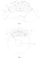
FIG. 1 is a schematic structure diagram illustrating a rotor structure according to a first embodiment of the present application; -
FIG. 2 is a schematic structure diagram illustrating a rotor structure according to a second embodiment of the present application; -
FIG. 3 is a schematic diagram illustrating current vectors in a weakened magnetic field and a deeply weakened magnetic field of a motor according to the present application; -
FIG. 4 is a diagram illustrating magnetic induction lines of the rotor structure in a weakened magnetic field according to an embodiment of the present application. The above-mentioned figures include the following reference numerals:- 10, rotor body;
- 11, inner layer permanent magnet slot;
- 12, outer layer permanent magnet slot; 13, rotation shaft hole;
- 21, first bent slot; 22, second bent slot; 23, third bent slot; 24, fourth bent slot;
- 30, stator; 31, stator teeth;
- 41, inner layer arm permanent magnet; 42, inner layer bottom permanent magnet;
- 43, outer layer arm permanent magnet;
- 51, end portion of inner layer arm permanent magnet slot; 52, end portion of outer layer arm permanent magnet slot; 53, first flux barrier; 54, second flux barrier.
- It should be noted that, under the premise of no conflict, the embodiments in the present application and the features included in the embodiments can be combined with each other. The present application will be described in details below with reference to the drawings in connection with the embodiments.
- Referring to
FIGS. 1 to 4 , a rotor structure is provided according to embodiments of the present application. - Specifically, the rotor structure includes a
rotor body 10. Therotor body 10 is provided with permanent magnet slots groups. The permanent magnet slots groups each include an outer layerpermanent magnet slot 12. Therotor body 10 is further provided with athird bent slot 23 and afourth bent slot 24. Thethird bent slot 23 is in communication with a first segment of the outer layerpermanent magnet slot 12, and thefourth bent slot 24 is in communication with a second segment of the outer layerpermanent magnet slot 12. A length directional geometric center line of thethird bent slot 23 and a length directional geometric center line of a first segment of the outer layer permanent magnet slot 12form a third angle. A length directional geometric center line of thefourth bent slot 24 and a length directional geometric center line of the second segment of the outer layerpermanent magnet slot 12 form a fourth angle. An extension line of a side wall of thethird bent slot 23 and an outer edge of therotor body 10 intersect at a first point, and an extension line of a side wall of thefourth bent slot 24 and the outer edge of therotor body 10 intersect at a second point. A1 denotes a central angle corresponding to an arc of a connection line of the first point and the second point, where A1 > 0.63 × 360°/p, where p denotes a number of poles of the rotor structure. - In the present embodiment, directions of magnetic induction lines are optimized by setting a relationship between the number p of poles of the rotor structure and the angle between the bent slots, thereby increasing output power of the permanent magnet torque, and further increasing power of the permanent magnet auxiliary synchronous reluctance motor (hereinafter referred to motor).
- In this embodiment, the
third bent slot 23 and thefourth bent slot 24 are disposed at two sides of a direct-axis (as shown inFIG. 1 , the direct-axis is the d-axis in the figure, and a quadrature-axis is the q-axis in the figure) of therotor body 10 respectively. An extension line of a side wall of thethird bent slot 23 proximate to the direct-axis and an outer edge of therotor body 10 intersect at a first point. An extension line of a side wall of thefourth bent slot 24 proximate to the direct-axis and the outer edge of therotor body 10 intersect at a second point, thus achieving a better effect of conducting the magnetic induction lines. - As shown in
FIG. 2 , the first segment of the outer layerpermanent magnet slot 12 extends outwardly in a radial direction of therotor body 10. The second segment of the outer layerpermanent magnet slot 12 extends outwardly in a radial direction of therotor body 10. An intermediate segment of the outer layerpermanent magnet slot 12 is arranged to protrude towards arotation shaft hole 13 of therotor body 10. Thus the distribution of the magnetic induction lines of each magnetic circuit can be further regulated, reducing a local saturation. - In an embodiment, the permanent magnet slots groups each further include an inner layer permanent magnet slot 11. The
rotor body 10 is further provided with afirst bent slot 21 and asecond bent slot 22. Thefirst bent slot 21 is in communication with a first segment of the inner layer permanent magnet slot 11. A length directional geometric center line of the first bent slot and a length directional geometric center line of the first segment of the inner layer permanent magnet slot 11 form a first angle. The secondbent slot 22 is in communication with a second segment of the inner layer permanent magnet slot 11. A length directional geometric center line of the second bent slot and a length directional geometric center line of the second segment of the inner layer permanent magnet slot 11 form a second angle. Thus, a better effect of conducting the magnetic induction lines can be realized. - As shown in
FIGS. 1 and2 , a first flux barrier 53 is formed between the outer edge of therotor body 10 and a side wall of the firstbent slot 21 and/or a side wall of the secondbent slot 22 proximate to the outer edge of therotor body 10, and asecond flux barrier 54 is formed between a side wall of the thirdbent slot 23 and/or a side wall of the fourthbent slot 24 proximate to the outer edge of therotor body 10 and the outer edge of therotor body 10, and 0. 18 × 360°/p > A2 + A3 > 0. 13 × 360°/p is satisfied, where A2 denotes a central angle corresponding to an arc of the first flux barrier 53, and A3 denotes a central angle corresponding to an arc of thesecond flux barrier 54. Thus, the reluctance torque ripple of the torque component of the motor is optimized. - A2<A3<1.5 ×Wt is satisfied, where Wt denotes a width of a stator slot. Thus, the torque ripple can be reduced.
- Further, 0.25<A2/ (A2+A3) <0.5 is satisfied. Such an arrangement ensures the salient pole ratio not to decrease significantly while increasing an area of a magnetic flux conduction portion at an outer periphery of the rotor, thereby increasing flux linkage of permanent magnets.
- In an embodiment, J denotes an angle formed by a tangent of the
rotor body 10 passing the first point and the extension line of the side wall of the thirdbent slot 23 proximate to the direct-axis, where J<155°. Alternatively, J1 denotes an angle formed by a tangent of therotor body 10 passing the second point and the extension line of the side wall of the fourthbent slot 24 proximate to the direct-axis, where J1<155°. Of course, the two requirements can be met simultaneously. Such an arrangement can mitigate torque ripples caused by the local magnetic saturation. - In an embodiment, the side wall of the third
bent slot 23 proximate to the direct-axis extends outwardly in a radial direction of therotor body 10 and spreads gradually away from the direct-axis. Alternatively, the side wall of the fourthbent slot 24 proximate to the direct-axis extends outwardly in the radial direction of therotor body 10 and spreads gradually away from the direct-axis. Of course, the two requirements can be met simultaneously. Thus a better effect of conducting the magnetic induction lines can be realized. - The rotor structures of the above embodiments can also be applied in the technical field of motor equipment. That is, according to another aspect of the present application, a permanent magnet auxiliary synchronous reluctance motor is provided. The permanent magnet auxiliary synchronous reluctance motor includes a rotor structure, and the rotor structure is any one of the above-mentioned rotor structures.
- The rotor structures of the above embodiments can also be applied in the technical field of vehicle equipment. That is, according to another aspect of the present application, an electric vehicle is provided. The electric vehicle includes a rotor structure, and the rotor structure is any one of the above-mentioned rotor structures.
- In an embodiment, a rotor is arranged inside a stator through a shaft hole. The stator 30 includes stator teeth 31. The stator 30 and the rotor have an air gap therebetween. The rotor has a plurality of poles. Each pole has a plurality of permanent magnet slots. Each permanent magnet slot is a hollow air slot, and penetrates in an axial direction of an iron core. Each permanent magnet is arranged in a corresponding permanent magnet slot. After being assembled, portions of the permanent magnet slots, which are proximate to the outer periphery of the rotor, are not fully filled and form an end portion 51 of an inner layer arm permanent magnet slot and an
end portion 52 of an outer layer arm permanent magnet slot. A first flux barrier 53 having a thin-wall structure is disposed between theend portion 52 of the outer layer arm permanent magnet slot and the air gap, and asecond flux barrier 54 having a thin-wall structure is disposed between the end portion 51 of the inner layer arm permanent magnet slot and the air gap, thus playing a role of structurally connecting punching sheets of the rotor as a whole, preventing the flux linkage passing through the magnetic circuit of the thin-wall structures in a magnetic saturation state to realize magnetic isolation. - In an embodiment, the permanent magnet slot is a U-shaped or V-shaped structure. The U-shaped structure can be integrated, that is, the sections of the integrated U-shaped structure are continuous. Of course, taking account of the complexity of the manufacturing process of a permanent magnet having an integrated U-shaped structure, the U-shaped structure can also be formed by combining a plurality of permanent magnet slots. For example, two inner layer arm permanent magnet slots and one inner layer bottom permanent magnet slot are shown in
FIG. 1 . The "plate-shaped" permanent magnets are correspondingly arranged in the permanent magnet slots, such as the inner layer armpermanent magnet 41, the inner layer bottompermanent magnet 42, and the outer layer armpermanent magnet 43. The inner layer permanent magnet slot and the outer layer permanent magnet slot both can be U-shaped, or both can be V-shaped, or can be a combination of being U-shaped or V-shaped. Compared with the main body portion of the permanent magnet slot, the end portions of the permanent magnet slot have a more obvious developing trend outwardly. The d-axis is a center line for each magnetic pole, that is, an open angle formed by the end portions of the permanent magnet slot is greater than an opening angle formed by the permanent magnet. The end portion of the permanent magnet slot is a portion starting from a point where the contour of the main portion of the permanent magnet slot is bent, even if the permanent magnet is not filled up to the bent point of the main portion of the permanent magnet slot. Two bent edges of the end portion of the permanent magnet slot are not parallel to each other, and one bent edge proximate to the d-axis has a larger bend. Thus, the smallest distance between the two bent edges is proximate to the outer periphery of the rotator, and the largest distance between the two bent edges is proximate to the bent point, so that the magnetic circuit can be adapted for different penetration depth of magnetic field according to different loads, and that the torque ripple maintains at a corresponding level for a fractional load and a large load. - In an embodiment, the reluctance torque component is affected by the reluctance of the magnetic circuit. The level of the torque ripple can be reduced when a central angle A2 corresponding to an arc of the internal layer flux barrier pole, a central angle A3 corresponding to an arc of the outer flux barrier pole, and a width Wt of a stator slot opening satisfy the following relationship. the central angle of the arc of the internal flux barrier and the central angle of the arc of the outer flux barrier: satisfy A2<A3<1.5 ×Wt. Furthermore, the increase of the permanent magnet torque component also has effects of improving the resultant torque ripple. In order to increase the permanent magnet torque component, the magnetic flux conduction area in the d-axial direction is increased, and a sum of the lengths (A2, A3) of the flux barriers at the end portions of the permanent magnet slots is limited to a certain percentage, thus the salient pole ratio can be ensured not to decrease significantly, while the area of the magnetic flux conduction portion at the outer periphery of the rotor is decreased, thereby increasing the flux linkage of permanent magnets, wherein A1, A2 and A3 satisfy the following relationship:


- Further, in a deeply weakened magnetic field, a d-axis component of a resultant current is1 increases; the q-axis component of the resultant current is1 decreases; and the saturation degree of the q-axis decreases. Therefore, it is more sensitive to the lengths of the flux barriers. The torque ripple can be ensured to be at a lower level in the deeply weakened magnetic field, when the following relationship can be satisfied.
- Excessive saturation of the flux circuit can also lead to the increase of the torque ripple, therefore circumscribed edges of the end portions of the outer layer arm permanent magnet slot proximate to the d-axis can only spread outwardly to a certain extent, otherwise a sharp angle will be formed at the end portions of the permanent magnet slots, thus causing a serious saturation. Therefore, during designing the circumscribed edges, an angle J, formed by the circumscribed edge and a tangent passing an intersection point of the circumscribed edge and the outer periphery of the rotor, is preferred less than 155°.
- Moreover, the above design analysis is based on the motor of a type 72S12P. Changes of slot-pole cooperation of the motor, scaling based on equal proportions, and limitations of changes of dimensions can be considered as a technology that can easily be mastered by those skilled in the art inspired by the present application.
- In view of the above description, it can be understood that the above-mentioned embodiments of the present application achieve the following technical effects.
- The ripple level of the reluctance torque of the torque components of the motor is optimized by designing the positions of the flux barriers at the end portions of the inner layer permanent magnet slot and the outer layer permanent magnet slot. The magnetic flux conduction area of the d-axis is increased by a structure of the circumscribed edges of the outer flux barrier. By increasing the percentage of the permanent magnet torque component and changing the phases of the permanent magnet torque and the reluctance torque, the peaks and valleys of the permanent magnet torque component and the reluctance torque component are staggered in time, thereby achieving a torque ripple of a low level. Through a research on the relationship of the lengths of the internal layer flux barrier and the outer layer flux barrier, the length of the internal flux barrier is set to be less than the length of the outer flux barrier in a reasonable range, thus the q-axis component is reduced in the deeply weakened magnetic field, and under the effect of the reduction of the saturation, it is more sensitive to the lengths of the flux barriers. In the case that the pre-designed value is small, the level of the torque ripple under the deeply weakened magnetic field can be improved.
- The above descriptions are merely preferred embodiments of the present application but not intended to limit the present application. For those skilled in the art, the present application may have various modifications and changes. Any modification, equivalent replacement, or improvement made within the spirit and principle of the present application shall fall in the protection scope of the present application.
Claims (11)
- A rotor structure, characterized by comprising:a rotor body (10) provided with permanent magnet slots groups, the permanent magnet slots groups each comprising an outer layer permanent magnet slot (12), the rotor body (10) being further provided with a third bent slot (23) and a fourth bent slot (24);wherein the third bent slot (23) is in communication with a first segment of the outer layer permanent magnet slot (12); the fourth bent slot (24) is in communication with a second segment of the outer layer permanent magnet slot (12); a length directional geometric center line of the third bent slot (23) and a length directional geometric center line of the first segment of the outer layer permanent magnet slot (12) form a third angle; a length directional geometric center line of the fourth bent slot (24) and a length directional geometric center line of the second segment of the outer layer permanent magnet slot (12) form a fourth angle;an extension line of a side wall of the third bent slot (23) and an outer edge of the rotor body (10) intersect at a first point; an extension line of a side wall of the fourth bent slot (24) and the outer edge of the rotor body (10) intersect at a second point; A1 denotes a central angle corresponding to an arc of a connection line of the first point and the second point; and A1>0.63×360°/p is satisfied, wherein p denotes a number of poles of the rotor structure.
- The rotor structure of claim 1, characterized in that the third bent slot (23) and the fourth bent slot (24) are disposed at two sides of a direct-axis of the rotor body (10) respectively; the extension line of the side wall of the third bent slot (23) proximate to the direct-axis and the outer edge of the rotor body (10) intersect at the first point; and the extension line of the side wall of the fourth bent slot (24) proximate to the direct-axis and the outer edge of the rotor body (10) intersect at the second point.
- The rotor structure of claim 1, characterized in that the first segment of the outer layer permanent magnet slot (12) extends outwardly in a radial direction of the rotor body (10); the second segment of the outer layer permanent magnet slot (12) extends outwardly in a radial direction of the rotor body (10); and an intermediate segment of the outer layer permanent magnet slot (12) is arranged to protrude towards a rotation shaft hole (13) of the rotor body (10).
- The rotor structure of claim 1, characterized in that the permanent magnet slots groups each further comprise an inner layer permanent magnet slot (11); the rotor body (10) is further provided with a first bent slot (21) and a second bent slot (22); the first bent slot (21) is in communication with a first segment of the inner layer permanent magnet slot (11); a length directional geometric center line of the first bent slot (21) and a length directional geometric center line of the first segment of the inner layer permanent magnet slot (11) form a first angle; the second bent slot (22) is in communication with a second segment of the inner layer permanent magnet slot (11) and a length directional geometric center line of the second bent slot (22) and a length directional geometric center line of the second segment of the inner layer permanent magnet slot (11) form a second angle.
- The rotor structure of claim 4, characterized in that
a first flux barrier (53) is formed between a side wall of the first bent slot (21) and/or the second bent slot (22) proximate to the outer edge of the rotor body (10), and the outer edge of the rotor body (10);
a second flux barrier (54) is formed between the outer edge of the rotor body (10) and a side wall of the third bent slot (23) and/or the fourth bent slot (24) proximate to the outer edge of the rotor body (10); and 0. 18 × 360°/p > A2 + A3 > 0. 13 × 360°/p is satisfied, A2 denotes a central angle corresponding to an arc of the first flux barrier (53), and A3 denotes a central angle corresponding to an arc of the second flux barrier (54). - The rotor structure of claim 5, characterized in that A2 < A3 < 1.5 ×Wt, and Wt denotes a width of a stator slot.
- The rotor structure of claim 5, characterized in that 0.25 < A2 / (A2 + A3) < 0.5 .
- The rotor structure of claim 2, characterized in that
J denotes an angle formed by a tangent of the rotor body (10) passing the first point and the extension line of the side wall of the third bent slot (23) proximate to the direct-axis, wherein J<155°; and/or
J1 denotes an angle formed by a tangent of the rotor body (10) passing the second point and the extension line of the side wall of the fourth bent slot (24) proximate to the direct-axis, wherein J1<155°. - The rotor structure of claim 2, characterized in that
the side wall of the third bent slot (23) proximate to the direct-axis extends outwardly in a radial direction of the rotor body (10) and spreads gradually away from the direct-axis, and/or
the side wall of the fourth bent slot (24) proximate to the direct-axis extends outwardly in a radial direction of the rotor body (10) and spreads gradually away from the direct-axis. - A permanent magnet auxiliary synchronous reluctance motor, characterized by comprising the rotor structure of any one of claims 1 to 9.
- An electric vehicle, characterized by comprising the rotor structure of any one of claims 1 to 9.
Applications Claiming Priority (2)
| Application Number | Priority Date | Filing Date | Title |
|---|---|---|---|
| CN201810219844.3A CN108566005B (en) | 2018-03-16 | 2018-03-16 | Rotor structure, permanent magnet auxiliary synchronous reluctance motor and electric automobile |
| PCT/CN2018/119781 WO2019174312A1 (en) | 2018-03-16 | 2018-12-07 | Rotor structure, permanent magnet auxiliary synchronous reluctance motor and electric automobile |
Publications (2)
| Publication Number | Publication Date |
|---|---|
| EP3767792A1 true EP3767792A1 (en) | 2021-01-20 |
| EP3767792A4 EP3767792A4 (en) | 2021-04-14 |
Family
ID=63532881
Family Applications (1)
| Application Number | Title | Priority Date | Filing Date |
|---|---|---|---|
| EP18909325.5A Pending EP3767792A4 (en) | 2018-03-16 | 2018-12-07 | ROTOR STRUCTURE, AUXILIARY PERMANENT MAGNET SYNCHRONOUS RELUCTANCE MOTOR AND ELECTRIC AUTOMOTIVE |
Country Status (4)
| Country | Link |
|---|---|
| US (1) | US11770038B2 (en) |
| EP (1) | EP3767792A4 (en) |
| CN (1) | CN108566005B (en) |
| WO (1) | WO2019174312A1 (en) |
Cited By (1)
| Publication number | Priority date | Publication date | Assignee | Title |
|---|---|---|---|---|
| EP4329153A1 (en) * | 2022-08-22 | 2024-02-28 | Sanyo Denki Co., Ltd. | Permanent magnet rotor with reduced torque ripple |
Families Citing this family (7)
| Publication number | Priority date | Publication date | Assignee | Title |
|---|---|---|---|---|
| CN108321954B (en) * | 2018-03-16 | 2020-10-23 | 珠海格力节能环保制冷技术研究中心有限公司 | Rotor structure, permanent magnet auxiliary synchronous reluctance motor and electric automobile |
| CN108566005B (en) * | 2018-03-16 | 2020-10-30 | 珠海格力节能环保制冷技术研究中心有限公司 | Rotor structure, permanent magnet auxiliary synchronous reluctance motor and electric automobile |
| CN108566006A (en) * | 2018-03-16 | 2018-09-21 | 珠海格力节能环保制冷技术研究中心有限公司 | Rotor structure, permanent magnetism assist in synchronization reluctance motor and electric vehicle |
| CN109861488B (en) * | 2019-03-21 | 2024-01-26 | 深圳市振桦电机有限公司 | Magnetic levitation components and electric toothbrushes |
| CN110994834B (en) * | 2019-11-28 | 2021-12-21 | 江苏大学 | Alternating-direct axis inductance variable permanent magnet brushless motor and wide-area efficient optimization design method thereof |
| CN114801088B (en) * | 2022-03-28 | 2025-01-07 | 宁波勤悦节能科技有限公司 | An electric melt adhesive structure of an injection molding machine |
| CN116742856B (en) * | 2023-07-03 | 2024-05-31 | 山东理工大学 | Magnetic field distribution adjustable motor with arc-shaped magnetic barriers |
Family Cites Families (29)
| Publication number | Priority date | Publication date | Assignee | Title |
|---|---|---|---|---|
| JP3605475B2 (en) * | 1996-08-06 | 2004-12-22 | 松下電器産業株式会社 | Permanent magnet synchronous motor |
| US6008559A (en) * | 1997-07-22 | 1999-12-28 | Matsushita Electric Industrial Co., Ltd. | Motor using a rotor including an interior permanent magnet |
| US6774521B2 (en) | 2001-05-16 | 2004-08-10 | Koyo Seiko Co., Ltd. | Brushless DC motor |
| JP5059614B2 (en) * | 2004-10-26 | 2012-10-24 | コルモーゲン コーポレイション | Structure of magnet and web in permanent magnet embedded rotor |
| JP4404223B2 (en) * | 2007-03-20 | 2010-01-27 | 株式会社安川電機 | Electromagnetic steel sheet forming body, electromagnetic steel sheet laminate, permanent magnet type synchronous rotating electric machine equipped with the same, permanent magnet type synchronous rotating electric machine, vehicle using the rotating electric machine, elevator, fluid machine, processing machine |
| EP2304863B1 (en) * | 2008-07-30 | 2018-06-27 | Regal Beloit America, Inc. | Interior permanent magnet motor including rotor with unequal poles |
| JP5360219B2 (en) * | 2009-08-31 | 2013-12-04 | 株式会社安川電機 | Rotor, permanent magnet type synchronous rotating electric machine, vehicle, elevator, fluid machine, and processing machine |
| JP5479978B2 (en) * | 2010-03-30 | 2014-04-23 | アイシン・エィ・ダブリュ株式会社 | Rotating electric machine |
| JP5643127B2 (en) | 2011-02-03 | 2014-12-17 | トヨタ自動車株式会社 | Rotating machine rotor |
| CN103023256B (en) * | 2011-09-26 | 2017-03-01 | 辐射通量实验室私人有限公司 | Magneto |
| JP5857627B2 (en) | 2011-10-27 | 2016-02-10 | スズキ株式会社 | Electric rotating machine |
| CN202444347U (en) * | 2012-03-05 | 2012-09-19 | 珠海格力节能环保制冷技术研究中心有限公司 | Permanent magnet auxiliary synchronous reluctance motor and rotor thereof |
| CN202444345U (en) | 2012-03-05 | 2012-09-19 | 珠海格力节能环保制冷技术研究中心有限公司 | Rotor of permanent magnet auxiliary synchronous magnetic reluctance motor and motor thereof |
| JP5974599B2 (en) * | 2012-04-12 | 2016-08-23 | 株式会社デンソー | Rotating electric machine |
| CN204089392U (en) * | 2014-10-17 | 2015-01-07 | 珠海格力节能环保制冷技术研究中心有限公司 | A kind of rotor and adopt its permagnetic synchronous motor |
| CN105703502A (en) | 2014-11-26 | 2016-06-22 | 天津市松正电动汽车技术股份有限公司 | Synchronous reluctance motor rotor structure |
| CN104638864A (en) * | 2015-02-16 | 2015-05-20 | 武汉华大新型电机科技股份有限公司 | Permanent magnet motor and method for accelerating rotating speed of permanent magnet motor |
| JP6390506B2 (en) * | 2015-04-28 | 2018-09-19 | 株式会社デンソー | Rotating electrical machine rotor |
| DE102015212127A1 (en) | 2015-06-30 | 2017-01-05 | Robert Bosch Gmbh | Permanently energized electric machine with optimized geometry |
| DE112016004565T5 (en) | 2015-10-06 | 2018-07-05 | Mitsubishi Electric Corporation | ELECTRICAL ROTATION MACHINE |
| CN106936284B (en) | 2015-12-29 | 2024-04-16 | 丹佛斯(天津)有限公司 | Electric Motor |
| CN205566051U (en) * | 2015-12-29 | 2016-09-07 | 丹佛斯(天津)有限公司 | Electric motor |
| CN105553143B (en) * | 2016-02-25 | 2019-06-07 | 珠海格力节能环保制冷技术研究中心有限公司 | Rotor core and permanent magnet synchronous motor with it |
| CN205693464U (en) * | 2016-06-08 | 2016-11-16 | 珠海格力节能环保制冷技术研究中心有限公司 | Core construction, rotor assembly and magneto |
| CN106329773B (en) | 2016-08-31 | 2018-11-27 | 恒大法拉第未来智能汽车(广东)有限公司 | Rotor, motor and the vehicle of motor |
| CN108336842B (en) | 2018-03-16 | 2020-10-16 | 珠海格力节能环保制冷技术研究中心有限公司 | Rotor structure, permanent magnet auxiliary synchronous reluctance motor and electric automobile |
| CN108566005B (en) | 2018-03-16 | 2020-10-30 | 珠海格力节能环保制冷技术研究中心有限公司 | Rotor structure, permanent magnet auxiliary synchronous reluctance motor and electric automobile |
| CN208015475U (en) | 2018-03-16 | 2018-10-26 | 珠海格力节能环保制冷技术研究中心有限公司 | Rotor structure, permanent magnetism assist in synchronization reluctance motor and electric vehicle |
| CN208015476U (en) * | 2018-03-16 | 2018-10-26 | 珠海格力节能环保制冷技术研究中心有限公司 | Rotor structure, permanent magnetism assist in synchronization reluctance motor and electric vehicle |
-
2018
- 2018-03-16 CN CN201810219844.3A patent/CN108566005B/en active Active
- 2018-12-07 WO PCT/CN2018/119781 patent/WO2019174312A1/en not_active Ceased
- 2018-12-07 US US16/981,255 patent/US11770038B2/en active Active
- 2018-12-07 EP EP18909325.5A patent/EP3767792A4/en active Pending
Cited By (2)
| Publication number | Priority date | Publication date | Assignee | Title |
|---|---|---|---|---|
| EP4329153A1 (en) * | 2022-08-22 | 2024-02-28 | Sanyo Denki Co., Ltd. | Permanent magnet rotor with reduced torque ripple |
| US12519355B2 (en) | 2022-08-22 | 2026-01-06 | Sanyo Denki Co., Ltd. | Rotor |
Also Published As
| Publication number | Publication date |
|---|---|
| US20210044166A1 (en) | 2021-02-11 |
| US11770038B2 (en) | 2023-09-26 |
| EP3767792A4 (en) | 2021-04-14 |
| CN108566005A (en) | 2018-09-21 |
| CN108566005B (en) | 2020-10-30 |
| WO2019174312A1 (en) | 2019-09-19 |
Similar Documents
| Publication | Publication Date | Title |
|---|---|---|
| EP3767792A1 (en) | Rotor structure, permanent magnet auxiliary synchronous reluctance motor and electric automobile | |
| EP3767795B1 (en) | Rotor structure, permanent magnet auxiliary synchronous reluctance motor, and electric vehicle | |
| CN104638863B (en) | A kind of permagnetic synchronous motor | |
| EP3089327B1 (en) | Permanent magnet motor | |
| EP3745560B1 (en) | Rotor structure, permanent magnet auxiliary synchronous reluctance motor and electric vehicle | |
| CN108321954B (en) | Rotor structure, permanent magnet auxiliary synchronous reluctance motor and electric automobile | |
| US12095311B2 (en) | Direct starting synchronous reluctance motor rotor and motor | |
| EP3767796B1 (en) | Rotor structure, permanent magnet auxiliary synchronous reluctance motor and electric vehicle | |
| US11699930B2 (en) | Rotor structure, permanent magnet auxiliary synchronous reluctance motor and electric vehicle | |
| US11799333B2 (en) | Permanent magnet auxiliary synchronous reluctance motor and electric vehicle provided with same | |
| CN112271838A (en) | Motor rotor with magnetic steel in double-V arrangement structure | |
| CN210839094U (en) | Rotor structure of direct-start synchronous reluctance motor and motor | |
| EP3926795A1 (en) | Direct start-up and synchronous reluctance motor rotor structure and motor comprising same | |
| CN108711973B (en) | Rotor structure, permanent magnet auxiliary synchronous reluctance motor and electric automobile | |
| CN210629214U (en) | Rotor structure and permanent magnet synchronous motor | |
| JP2019186973A (en) | Permanent magnet motor | |
| JP2012139068A (en) | Rotor for embedded magnet type motor | |
| CN120546320A (en) | A wide-area high-efficiency permanent magnet brushless motor with enhanced winding function and its design method | |
| CN213906402U (en) | Motor rotor with magnetic steel in double-V arrangement structure | |
| CN209562264U (en) | Motor rotor, motor and compressor | |
| JP5451090B2 (en) | Rotating electric machine |
Legal Events
| Date | Code | Title | Description |
|---|---|---|---|
| STAA | Information on the status of an ep patent application or granted ep patent |
Free format text: STATUS: THE INTERNATIONAL PUBLICATION HAS BEEN MADE |
|
| PUAI | Public reference made under article 153(3) epc to a published international application that has entered the european phase |
Free format text: ORIGINAL CODE: 0009012 |
|
| STAA | Information on the status of an ep patent application or granted ep patent |
Free format text: STATUS: REQUEST FOR EXAMINATION WAS MADE |
|
| 17P | Request for examination filed |
Effective date: 20200831 |
|
| AK | Designated contracting states |
Kind code of ref document: A1 Designated state(s): AL AT BE BG CH CY CZ DE DK EE ES FI FR GB GR HR HU IE IS IT LI LT LU LV MC MK MT NL NO PL PT RO RS SE SI SK SM TR |
|
| AX | Request for extension of the european patent |
Extension state: BA ME |
|
| A4 | Supplementary search report drawn up and despatched |
Effective date: 20210317 |
|
| RIC1 | Information provided on ipc code assigned before grant |
Ipc: H02K 1/27 20060101AFI20210311BHEP Ipc: H02K 29/03 20060101ALI20210311BHEP Ipc: H02K 21/14 20060101ALN20210311BHEP |
|
| DAV | Request for validation of the european patent (deleted) | ||
| DAX | Request for extension of the european patent (deleted) | ||
| STAA | Information on the status of an ep patent application or granted ep patent |
Free format text: STATUS: EXAMINATION IS IN PROGRESS |
|
| 17Q | First examination report despatched |
Effective date: 20230323 |
|
| P01 | Opt-out of the competence of the unified patent court (upc) registered |
Effective date: 20230530 |
|
| GRAP | Despatch of communication of intention to grant a patent |
Free format text: ORIGINAL CODE: EPIDOSNIGR1 |
|
| STAA | Information on the status of an ep patent application or granted ep patent |
Free format text: STATUS: GRANT OF PATENT IS INTENDED |
|
| RIC1 | Information provided on ipc code assigned before grant |
Ipc: H02K 1/27 20060101AFI20251220BHEP Ipc: H02K 29/03 20060101ALI20251220BHEP Ipc: H02K 1/276 20220101ALI20251220BHEP Ipc: H02K 21/14 20060101ALN20251220BHEP |
|
| INTG | Intention to grant announced |
Effective date: 20260127 |
|
| RIC1 | Information provided on ipc code assigned before grant |
Ipc: H02K 1/27 20060101AFI20260118BHEP Ipc: H02K 29/03 20060101ALI20260118BHEP Ipc: H02K 1/276 20220101ALI20260118BHEP Ipc: H02K 21/14 20060101ALN20260118BHEP |
|
| GRAS | Grant fee paid |
Free format text: ORIGINAL CODE: EPIDOSNIGR3 |
|
| GRAA | (expected) grant |
Free format text: ORIGINAL CODE: 0009210 |
|
| STAA | Information on the status of an ep patent application or granted ep patent |
Free format text: STATUS: THE PATENT HAS BEEN GRANTED |