EP3767786B1 - Construction equipment - Google Patents
Construction equipment Download PDFInfo
- Publication number
- EP3767786B1 EP3767786B1 EP19767991.3A EP19767991A EP3767786B1 EP 3767786 B1 EP3767786 B1 EP 3767786B1 EP 19767991 A EP19767991 A EP 19767991A EP 3767786 B1 EP3767786 B1 EP 3767786B1
- Authority
- EP
- European Patent Office
- Prior art keywords
- time
- battery
- balancing
- state
- key switch
- Prior art date
- Legal status (The legal status is an assumption and is not a legal conclusion. Google has not performed a legal analysis and makes no representation as to the accuracy of the status listed.)
- Active
Links
Images

Classifications
-
- B—PERFORMING OPERATIONS; TRANSPORTING
- B60—VEHICLES IN GENERAL
- B60L—PROPULSION OF ELECTRICALLY-PROPELLED VEHICLES; SUPPLYING ELECTRIC POWER FOR AUXILIARY EQUIPMENT OF ELECTRICALLY-PROPELLED VEHICLES; ELECTRODYNAMIC BRAKE SYSTEMS FOR VEHICLES IN GENERAL; MAGNETIC SUSPENSION OR LEVITATION FOR VEHICLES; MONITORING OPERATING VARIABLES OF ELECTRICALLY-PROPELLED VEHICLES; ELECTRIC SAFETY DEVICES FOR ELECTRICALLY-PROPELLED VEHICLES
- B60L1/00—Supplying electric power to auxiliary equipment of vehicles
- B60L1/003—Supplying electric power to auxiliary equipment of vehicles to auxiliary motors, e.g. for pumps, compressors
-
- B—PERFORMING OPERATIONS; TRANSPORTING
- B60—VEHICLES IN GENERAL
- B60L—PROPULSION OF ELECTRICALLY-PROPELLED VEHICLES; SUPPLYING ELECTRIC POWER FOR AUXILIARY EQUIPMENT OF ELECTRICALLY-PROPELLED VEHICLES; ELECTRODYNAMIC BRAKE SYSTEMS FOR VEHICLES IN GENERAL; MAGNETIC SUSPENSION OR LEVITATION FOR VEHICLES; MONITORING OPERATING VARIABLES OF ELECTRICALLY-PROPELLED VEHICLES; ELECTRIC SAFETY DEVICES FOR ELECTRICALLY-PROPELLED VEHICLES
- B60L50/00—Electric propulsion with power supplied within the vehicle
- B60L50/50—Electric propulsion with power supplied within the vehicle using propulsion power supplied by batteries or fuel cells
- B60L50/60—Electric propulsion with power supplied within the vehicle using propulsion power supplied by batteries or fuel cells using power supplied by batteries
- B60L50/61—Electric propulsion with power supplied within the vehicle using propulsion power supplied by batteries or fuel cells using power supplied by batteries by batteries charged by engine-driven generators, e.g. series hybrid electric vehicles
-
- B—PERFORMING OPERATIONS; TRANSPORTING
- B60—VEHICLES IN GENERAL
- B60L—PROPULSION OF ELECTRICALLY-PROPELLED VEHICLES; SUPPLYING ELECTRIC POWER FOR AUXILIARY EQUIPMENT OF ELECTRICALLY-PROPELLED VEHICLES; ELECTRODYNAMIC BRAKE SYSTEMS FOR VEHICLES IN GENERAL; MAGNETIC SUSPENSION OR LEVITATION FOR VEHICLES; MONITORING OPERATING VARIABLES OF ELECTRICALLY-PROPELLED VEHICLES; ELECTRIC SAFETY DEVICES FOR ELECTRICALLY-PROPELLED VEHICLES
- B60L50/00—Electric propulsion with power supplied within the vehicle
- B60L50/50—Electric propulsion with power supplied within the vehicle using propulsion power supplied by batteries or fuel cells
- B60L50/60—Electric propulsion with power supplied within the vehicle using propulsion power supplied by batteries or fuel cells using power supplied by batteries
- B60L50/66—Arrangements of batteries
-
- B—PERFORMING OPERATIONS; TRANSPORTING
- B60—VEHICLES IN GENERAL
- B60L—PROPULSION OF ELECTRICALLY-PROPELLED VEHICLES; SUPPLYING ELECTRIC POWER FOR AUXILIARY EQUIPMENT OF ELECTRICALLY-PROPELLED VEHICLES; ELECTRODYNAMIC BRAKE SYSTEMS FOR VEHICLES IN GENERAL; MAGNETIC SUSPENSION OR LEVITATION FOR VEHICLES; MONITORING OPERATING VARIABLES OF ELECTRICALLY-PROPELLED VEHICLES; ELECTRIC SAFETY DEVICES FOR ELECTRICALLY-PROPELLED VEHICLES
- B60L53/00—Methods of charging batteries, specially adapted for electric vehicles; Charging stations or on-board charging equipment therefor; Exchange of energy storage elements in electric vehicles
- B60L53/10—Methods of charging batteries, specially adapted for electric vehicles; Charging stations or on-board charging equipment therefor; Exchange of energy storage elements in electric vehicles characterised by the energy transfer between the charging station and the vehicle
- B60L53/14—Conductive energy transfer
-
- B—PERFORMING OPERATIONS; TRANSPORTING
- B60—VEHICLES IN GENERAL
- B60L—PROPULSION OF ELECTRICALLY-PROPELLED VEHICLES; SUPPLYING ELECTRIC POWER FOR AUXILIARY EQUIPMENT OF ELECTRICALLY-PROPELLED VEHICLES; ELECTRODYNAMIC BRAKE SYSTEMS FOR VEHICLES IN GENERAL; MAGNETIC SUSPENSION OR LEVITATION FOR VEHICLES; MONITORING OPERATING VARIABLES OF ELECTRICALLY-PROPELLED VEHICLES; ELECTRIC SAFETY DEVICES FOR ELECTRICALLY-PROPELLED VEHICLES
- B60L58/00—Methods or circuit arrangements for monitoring or controlling batteries or fuel cells, specially adapted for electric vehicles
- B60L58/10—Methods or circuit arrangements for monitoring or controlling batteries or fuel cells, specially adapted for electric vehicles for monitoring or controlling batteries
- B60L58/12—Methods or circuit arrangements for monitoring or controlling batteries or fuel cells, specially adapted for electric vehicles for monitoring or controlling batteries responding to state of charge [SoC]
-
- B—PERFORMING OPERATIONS; TRANSPORTING
- B60—VEHICLES IN GENERAL
- B60L—PROPULSION OF ELECTRICALLY-PROPELLED VEHICLES; SUPPLYING ELECTRIC POWER FOR AUXILIARY EQUIPMENT OF ELECTRICALLY-PROPELLED VEHICLES; ELECTRODYNAMIC BRAKE SYSTEMS FOR VEHICLES IN GENERAL; MAGNETIC SUSPENSION OR LEVITATION FOR VEHICLES; MONITORING OPERATING VARIABLES OF ELECTRICALLY-PROPELLED VEHICLES; ELECTRIC SAFETY DEVICES FOR ELECTRICALLY-PROPELLED VEHICLES
- B60L58/00—Methods or circuit arrangements for monitoring or controlling batteries or fuel cells, specially adapted for electric vehicles
- B60L58/10—Methods or circuit arrangements for monitoring or controlling batteries or fuel cells, specially adapted for electric vehicles for monitoring or controlling batteries
- B60L58/18—Methods or circuit arrangements for monitoring or controlling batteries or fuel cells, specially adapted for electric vehicles for monitoring or controlling batteries of two or more battery modules
- B60L58/19—Switching between serial connection and parallel connection of battery modules
-
- B—PERFORMING OPERATIONS; TRANSPORTING
- B60—VEHICLES IN GENERAL
- B60L—PROPULSION OF ELECTRICALLY-PROPELLED VEHICLES; SUPPLYING ELECTRIC POWER FOR AUXILIARY EQUIPMENT OF ELECTRICALLY-PROPELLED VEHICLES; ELECTRODYNAMIC BRAKE SYSTEMS FOR VEHICLES IN GENERAL; MAGNETIC SUSPENSION OR LEVITATION FOR VEHICLES; MONITORING OPERATING VARIABLES OF ELECTRICALLY-PROPELLED VEHICLES; ELECTRIC SAFETY DEVICES FOR ELECTRICALLY-PROPELLED VEHICLES
- B60L58/00—Methods or circuit arrangements for monitoring or controlling batteries or fuel cells, specially adapted for electric vehicles
- B60L58/10—Methods or circuit arrangements for monitoring or controlling batteries or fuel cells, specially adapted for electric vehicles for monitoring or controlling batteries
- B60L58/18—Methods or circuit arrangements for monitoring or controlling batteries or fuel cells, specially adapted for electric vehicles for monitoring or controlling batteries of two or more battery modules
- B60L58/20—Methods or circuit arrangements for monitoring or controlling batteries or fuel cells, specially adapted for electric vehicles for monitoring or controlling batteries of two or more battery modules having different nominal voltages
-
- B—PERFORMING OPERATIONS; TRANSPORTING
- B60—VEHICLES IN GENERAL
- B60L—PROPULSION OF ELECTRICALLY-PROPELLED VEHICLES; SUPPLYING ELECTRIC POWER FOR AUXILIARY EQUIPMENT OF ELECTRICALLY-PROPELLED VEHICLES; ELECTRODYNAMIC BRAKE SYSTEMS FOR VEHICLES IN GENERAL; MAGNETIC SUSPENSION OR LEVITATION FOR VEHICLES; MONITORING OPERATING VARIABLES OF ELECTRICALLY-PROPELLED VEHICLES; ELECTRIC SAFETY DEVICES FOR ELECTRICALLY-PROPELLED VEHICLES
- B60L58/00—Methods or circuit arrangements for monitoring or controlling batteries or fuel cells, specially adapted for electric vehicles
- B60L58/10—Methods or circuit arrangements for monitoring or controlling batteries or fuel cells, specially adapted for electric vehicles for monitoring or controlling batteries
- B60L58/18—Methods or circuit arrangements for monitoring or controlling batteries or fuel cells, specially adapted for electric vehicles for monitoring or controlling batteries of two or more battery modules
- B60L58/22—Balancing the charge of battery modules
-
- E—FIXED CONSTRUCTIONS
- E02—HYDRAULIC ENGINEERING; FOUNDATIONS; SOIL SHIFTING
- E02F—DREDGING; SOIL-SHIFTING
- E02F3/00—Dredgers; Soil-shifting machines
- E02F3/04—Dredgers; Soil-shifting machines mechanically-driven
- E02F3/28—Dredgers; Soil-shifting machines mechanically-driven with digging tools mounted on a dipper- or bucket-arm, i.e. there is either one arm or a pair of arms, e.g. dippers, buckets
- E02F3/30—Dredgers; Soil-shifting machines mechanically-driven with digging tools mounted on a dipper- or bucket-arm, i.e. there is either one arm or a pair of arms, e.g. dippers, buckets with a dipper-arm pivoted on a cantilever beam, i.e. boom
- E02F3/32—Dredgers; Soil-shifting machines mechanically-driven with digging tools mounted on a dipper- or bucket-arm, i.e. there is either one arm or a pair of arms, e.g. dippers, buckets with a dipper-arm pivoted on a cantilever beam, i.e. boom working downwardly and towards the machine, e.g. with backhoes
-
- E—FIXED CONSTRUCTIONS
- E02—HYDRAULIC ENGINEERING; FOUNDATIONS; SOIL SHIFTING
- E02F—DREDGING; SOIL-SHIFTING
- E02F9/00—Component parts of dredgers or soil-shifting machines, not restricted to one of the kinds covered by groups E02F3/00 - E02F7/00
- E02F9/20—Drives; Control devices
- E02F9/2058—Electric or electro-mechanical or mechanical control devices of vehicle sub-units
- E02F9/2091—Control of energy storage means for electrical energy, e.g. battery or capacitors
-
- H—ELECTRICITY
- H01—ELECTRIC ELEMENTS
- H01M—PROCESSES OR MEANS, e.g. BATTERIES, FOR THE DIRECT CONVERSION OF CHEMICAL ENERGY INTO ELECTRICAL ENERGY
- H01M10/00—Secondary cells; Manufacture thereof
- H01M10/42—Methods or arrangements for servicing or maintenance of secondary cells or secondary half-cells
- H01M10/44—Methods for charging or discharging
-
- H—ELECTRICITY
- H01—ELECTRIC ELEMENTS
- H01M—PROCESSES OR MEANS, e.g. BATTERIES, FOR THE DIRECT CONVERSION OF CHEMICAL ENERGY INTO ELECTRICAL ENERGY
- H01M10/00—Secondary cells; Manufacture thereof
- H01M10/42—Methods or arrangements for servicing or maintenance of secondary cells or secondary half-cells
- H01M10/48—Accumulators combined with arrangements for measuring, testing or indicating the condition of cells, e.g. the level or density of the electrolyte
- H01M10/482—Accumulators combined with arrangements for measuring, testing or indicating the condition of cells, e.g. the level or density of the electrolyte for several batteries or cells simultaneously or sequentially
-
- H—ELECTRICITY
- H02—GENERATION; CONVERSION OR DISTRIBUTION OF ELECTRIC POWER
- H02J—CIRCUIT ARRANGEMENTS OR SYSTEMS FOR SUPPLYING OR DISTRIBUTING ELECTRIC POWER; SYSTEMS FOR STORING ELECTRIC ENERGY
- H02J7/00—Circuit arrangements for charging or depolarising batteries or for supplying loads from batteries
- H02J7/0013—Circuit arrangements for charging or depolarising batteries or for supplying loads from batteries acting upon several batteries simultaneously or sequentially
- H02J7/0014—Circuits for equalisation of charge between batteries
- H02J7/0019—Circuits for equalisation of charge between batteries using switched or multiplexed charge circuits
-
- H—ELECTRICITY
- H02—GENERATION; CONVERSION OR DISTRIBUTION OF ELECTRIC POWER
- H02J—CIRCUIT ARRANGEMENTS OR SYSTEMS FOR SUPPLYING OR DISTRIBUTING ELECTRIC POWER; SYSTEMS FOR STORING ELECTRIC ENERGY
- H02J7/00—Circuit arrangements for charging or depolarising batteries or for supplying loads from batteries
- H02J7/0047—Circuit arrangements for charging or depolarising batteries or for supplying loads from batteries with monitoring or indicating devices or circuits
-
- H—ELECTRICITY
- H02—GENERATION; CONVERSION OR DISTRIBUTION OF ELECTRIC POWER
- H02J—CIRCUIT ARRANGEMENTS OR SYSTEMS FOR SUPPLYING OR DISTRIBUTING ELECTRIC POWER; SYSTEMS FOR STORING ELECTRIC ENERGY
- H02J7/00—Circuit arrangements for charging or depolarising batteries or for supplying loads from batteries
- H02J7/14—Circuit arrangements for charging or depolarising batteries or for supplying loads from batteries for charging batteries from dynamo-electric generators driven at varying speed, e.g. on vehicle
- H02J7/1446—Circuit arrangements for charging or depolarising batteries or for supplying loads from batteries for charging batteries from dynamo-electric generators driven at varying speed, e.g. on vehicle in response to parameters of a vehicle
-
- B—PERFORMING OPERATIONS; TRANSPORTING
- B60—VEHICLES IN GENERAL
- B60L—PROPULSION OF ELECTRICALLY-PROPELLED VEHICLES; SUPPLYING ELECTRIC POWER FOR AUXILIARY EQUIPMENT OF ELECTRICALLY-PROPELLED VEHICLES; ELECTRODYNAMIC BRAKE SYSTEMS FOR VEHICLES IN GENERAL; MAGNETIC SUSPENSION OR LEVITATION FOR VEHICLES; MONITORING OPERATING VARIABLES OF ELECTRICALLY-PROPELLED VEHICLES; ELECTRIC SAFETY DEVICES FOR ELECTRICALLY-PROPELLED VEHICLES
- B60L2200/00—Type of vehicles
- B60L2200/40—Working vehicles
-
- B—PERFORMING OPERATIONS; TRANSPORTING
- B60—VEHICLES IN GENERAL
- B60L—PROPULSION OF ELECTRICALLY-PROPELLED VEHICLES; SUPPLYING ELECTRIC POWER FOR AUXILIARY EQUIPMENT OF ELECTRICALLY-PROPELLED VEHICLES; ELECTRODYNAMIC BRAKE SYSTEMS FOR VEHICLES IN GENERAL; MAGNETIC SUSPENSION OR LEVITATION FOR VEHICLES; MONITORING OPERATING VARIABLES OF ELECTRICALLY-PROPELLED VEHICLES; ELECTRIC SAFETY DEVICES FOR ELECTRICALLY-PROPELLED VEHICLES
- B60L2240/00—Control parameters of input or output; Target parameters
- B60L2240/40—Drive Train control parameters
- B60L2240/54—Drive Train control parameters related to batteries
- B60L2240/547—Voltage
-
- B—PERFORMING OPERATIONS; TRANSPORTING
- B60—VEHICLES IN GENERAL
- B60L—PROPULSION OF ELECTRICALLY-PROPELLED VEHICLES; SUPPLYING ELECTRIC POWER FOR AUXILIARY EQUIPMENT OF ELECTRICALLY-PROPELLED VEHICLES; ELECTRODYNAMIC BRAKE SYSTEMS FOR VEHICLES IN GENERAL; MAGNETIC SUSPENSION OR LEVITATION FOR VEHICLES; MONITORING OPERATING VARIABLES OF ELECTRICALLY-PROPELLED VEHICLES; ELECTRIC SAFETY DEVICES FOR ELECTRICALLY-PROPELLED VEHICLES
- B60L2240/00—Control parameters of input or output; Target parameters
- B60L2240/80—Time limits
-
- B—PERFORMING OPERATIONS; TRANSPORTING
- B60—VEHICLES IN GENERAL
- B60L—PROPULSION OF ELECTRICALLY-PROPELLED VEHICLES; SUPPLYING ELECTRIC POWER FOR AUXILIARY EQUIPMENT OF ELECTRICALLY-PROPELLED VEHICLES; ELECTRODYNAMIC BRAKE SYSTEMS FOR VEHICLES IN GENERAL; MAGNETIC SUSPENSION OR LEVITATION FOR VEHICLES; MONITORING OPERATING VARIABLES OF ELECTRICALLY-PROPELLED VEHICLES; ELECTRIC SAFETY DEVICES FOR ELECTRICALLY-PROPELLED VEHICLES
- B60L2250/00—Driver interactions
- B60L2250/16—Driver interactions by display
-
- B—PERFORMING OPERATIONS; TRANSPORTING
- B60—VEHICLES IN GENERAL
- B60Y—INDEXING SCHEME RELATING TO ASPECTS CROSS-CUTTING VEHICLE TECHNOLOGY
- B60Y2200/00—Type of vehicle
- B60Y2200/40—Special vehicles
- B60Y2200/41—Construction vehicles, e.g. graders, excavators
-
- H—ELECTRICITY
- H01—ELECTRIC ELEMENTS
- H01M—PROCESSES OR MEANS, e.g. BATTERIES, FOR THE DIRECT CONVERSION OF CHEMICAL ENERGY INTO ELECTRICAL ENERGY
- H01M10/00—Secondary cells; Manufacture thereof
- H01M10/42—Methods or arrangements for servicing or maintenance of secondary cells or secondary half-cells
- H01M10/425—Structural combination with electronic components, e.g. electronic circuits integrated to the outside of the casing
- H01M2010/4271—Battery management systems including electronic circuits, e.g. control of current or voltage to keep battery in healthy state, cell balancing
-
- H—ELECTRICITY
- H01—ELECTRIC ELEMENTS
- H01M—PROCESSES OR MEANS, e.g. BATTERIES, FOR THE DIRECT CONVERSION OF CHEMICAL ENERGY INTO ELECTRICAL ENERGY
- H01M2220/00—Batteries for particular applications
- H01M2220/20—Batteries in motive systems, e.g. vehicle, ship, plane
-
- H—ELECTRICITY
- H02—GENERATION; CONVERSION OR DISTRIBUTION OF ELECTRIC POWER
- H02P—CONTROL OR REGULATION OF ELECTRIC MOTORS, ELECTRIC GENERATORS OR DYNAMO-ELECTRIC CONVERTERS; CONTROLLING TRANSFORMERS, REACTORS OR CHOKE COILS
- H02P27/00—Arrangements or methods for the control of AC motors characterised by the kind of supply voltage
- H02P27/04—Arrangements or methods for the control of AC motors characterised by the kind of supply voltage using variable-frequency supply voltage, e.g. inverter or converter supply voltage
- H02P27/06—Arrangements or methods for the control of AC motors characterised by the kind of supply voltage using variable-frequency supply voltage, e.g. inverter or converter supply voltage using DC to AC converters or inverters
-
- Y—GENERAL TAGGING OF NEW TECHNOLOGICAL DEVELOPMENTS; GENERAL TAGGING OF CROSS-SECTIONAL TECHNOLOGIES SPANNING OVER SEVERAL SECTIONS OF THE IPC; TECHNICAL SUBJECTS COVERED BY FORMER USPC CROSS-REFERENCE ART COLLECTIONS [XRACs] AND DIGESTS
- Y02—TECHNOLOGIES OR APPLICATIONS FOR MITIGATION OR ADAPTATION AGAINST CLIMATE CHANGE
- Y02E—REDUCTION OF GREENHOUSE GAS [GHG] EMISSIONS, RELATED TO ENERGY GENERATION, TRANSMISSION OR DISTRIBUTION
- Y02E60/00—Enabling technologies; Technologies with a potential or indirect contribution to GHG emissions mitigation
- Y02E60/10—Energy storage using batteries
-
- Y—GENERAL TAGGING OF NEW TECHNOLOGICAL DEVELOPMENTS; GENERAL TAGGING OF CROSS-SECTIONAL TECHNOLOGIES SPANNING OVER SEVERAL SECTIONS OF THE IPC; TECHNICAL SUBJECTS COVERED BY FORMER USPC CROSS-REFERENCE ART COLLECTIONS [XRACs] AND DIGESTS
- Y02—TECHNOLOGIES OR APPLICATIONS FOR MITIGATION OR ADAPTATION AGAINST CLIMATE CHANGE
- Y02T—CLIMATE CHANGE MITIGATION TECHNOLOGIES RELATED TO TRANSPORTATION
- Y02T10/00—Road transport of goods or passengers
- Y02T10/60—Other road transportation technologies with climate change mitigation effect
- Y02T10/62—Hybrid vehicles
-
- Y—GENERAL TAGGING OF NEW TECHNOLOGICAL DEVELOPMENTS; GENERAL TAGGING OF CROSS-SECTIONAL TECHNOLOGIES SPANNING OVER SEVERAL SECTIONS OF THE IPC; TECHNICAL SUBJECTS COVERED BY FORMER USPC CROSS-REFERENCE ART COLLECTIONS [XRACs] AND DIGESTS
- Y02—TECHNOLOGIES OR APPLICATIONS FOR MITIGATION OR ADAPTATION AGAINST CLIMATE CHANGE
- Y02T—CLIMATE CHANGE MITIGATION TECHNOLOGIES RELATED TO TRANSPORTATION
- Y02T10/00—Road transport of goods or passengers
- Y02T10/60—Other road transportation technologies with climate change mitigation effect
- Y02T10/70—Energy storage systems for electromobility, e.g. batteries
-
- Y—GENERAL TAGGING OF NEW TECHNOLOGICAL DEVELOPMENTS; GENERAL TAGGING OF CROSS-SECTIONAL TECHNOLOGIES SPANNING OVER SEVERAL SECTIONS OF THE IPC; TECHNICAL SUBJECTS COVERED BY FORMER USPC CROSS-REFERENCE ART COLLECTIONS [XRACs] AND DIGESTS
- Y02—TECHNOLOGIES OR APPLICATIONS FOR MITIGATION OR ADAPTATION AGAINST CLIMATE CHANGE
- Y02T—CLIMATE CHANGE MITIGATION TECHNOLOGIES RELATED TO TRANSPORTATION
- Y02T10/00—Road transport of goods or passengers
- Y02T10/60—Other road transportation technologies with climate change mitigation effect
- Y02T10/7072—Electromobility specific charging systems or methods for batteries, ultracapacitors, supercapacitors or double-layer capacitors
-
- Y—GENERAL TAGGING OF NEW TECHNOLOGICAL DEVELOPMENTS; GENERAL TAGGING OF CROSS-SECTIONAL TECHNOLOGIES SPANNING OVER SEVERAL SECTIONS OF THE IPC; TECHNICAL SUBJECTS COVERED BY FORMER USPC CROSS-REFERENCE ART COLLECTIONS [XRACs] AND DIGESTS
- Y02—TECHNOLOGIES OR APPLICATIONS FOR MITIGATION OR ADAPTATION AGAINST CLIMATE CHANGE
- Y02T—CLIMATE CHANGE MITIGATION TECHNOLOGIES RELATED TO TRANSPORTATION
- Y02T10/00—Road transport of goods or passengers
- Y02T10/80—Technologies aiming to reduce greenhouse gasses emissions common to all road transportation technologies
- Y02T10/92—Energy efficient charging or discharging systems for batteries, ultracapacitors, supercapacitors or double-layer capacitors specially adapted for vehicles
-
- Y—GENERAL TAGGING OF NEW TECHNOLOGICAL DEVELOPMENTS; GENERAL TAGGING OF CROSS-SECTIONAL TECHNOLOGIES SPANNING OVER SEVERAL SECTIONS OF THE IPC; TECHNICAL SUBJECTS COVERED BY FORMER USPC CROSS-REFERENCE ART COLLECTIONS [XRACs] AND DIGESTS
- Y02—TECHNOLOGIES OR APPLICATIONS FOR MITIGATION OR ADAPTATION AGAINST CLIMATE CHANGE
- Y02T—CLIMATE CHANGE MITIGATION TECHNOLOGIES RELATED TO TRANSPORTATION
- Y02T90/00—Enabling technologies or technologies with a potential or indirect contribution to GHG emissions mitigation
- Y02T90/10—Technologies relating to charging of electric vehicles
- Y02T90/14—Plug-in electric vehicles
Definitions
- the present invention relates to a construction machine such as a hydraulic excavator.
- a construction machine provided with an electric motor as a drive source of a vehicle body.
- power is supplied to the electric motor from a battery unit.
- the battery unit is configured of a plurality of cells series-connected for achieving a large capacity of the power.
- the battery unit performs charging or discharging at the time of driving the electric motor. At this time, each cell is required to be used within a range between an upper limit voltage and a lower limit voltage for preventing the performance degradation of the battery unit.
- the cell in the battery unit naturally discharges a little by a little by an influence of an internal resistance, for example.
- the discharge amount varies for each cell.
- the discharge amount for each cell varies the more greatly.
- Patent Document 1 discloses the configuration that for equalizing the charging rate between the cells based upon cell information in relation to a plurality of cells, only cells the charging rate of which is high are selected to be discharged. This discharging is executed from a point where a key switch is turned on and a vehicle body is activated to a point where the equalization of the charging rate between the cells is completed.
- Patent Document 2 discloses the configuration that a signal is sent to a power source part for each preset periodic time to launch a control part of the balancing control and periodically execute the balancing control.
- Patent Document 3 discloses the configuration that first, the control part of the balancing control is activated, and in that state, the determination part of the balancing control is activated for each preset periodic time.
- Patent Document 4 shows a shovel comprising: a lower traveling body; an upper turning body turnably mounted to the lower traveling body; a boom having one end rotatably attached on the upper rotating body; an arm having one end rotatably attached to the other end of the boom; a bucket rotatably attached to the other end of the arm; a capacitor with a plurality of capacitor cells mounted to the upper turning body; a power storage management device equalizing the cell voltage of each of the capacitor cells; and a controller exchanging information with the power storage management device.
- the power storage management device equalizes the cell voltage of each of the capacitor cells.
- Patent Document 5 shows a cell control device including a discharge circuit discharging each unit cell selected by first switches among a plurality of unit cells connected in series; a charging circuit charging each unit cell selected by second switches among the unit cells connected in series, a voltage detection unit detecting a voltage of each unit cell via voltage detection lines connected to positive and negative electrodes of the unit cells; an oscillator irradiating high frequency electromagnetic radiation upon the voltage detection lines; and a charging control unit controlling switching of the first switches, performing discharge of the each unit cell, and a charging control unit controlling switching of the second switches, performing charging of the unit cells, based on voltages of the unit cells detected by the voltage detection unit.
- Patent Document 1 Japanese Patent Laid-Open No. 2009-89484 A
- Patent Document 2 WO 2014/061153 A1 ( Japanese Patent No. 5980943 )
- Patent Document 3 Japanese Patent Laid-Open No. 2014-18038 A ( Japanese Patent No. 5831376 )
- Patent Document 4 JP WO20 1412 2869 A1
- Patent Document 5 US 2012/161708 A
- Patent document 4 relates to an excavator comprising a system for balancing charge of a battery.
- Patent document 5 relates to a cell control device for controlling charging and discharging of cells in an electricity storage device of a vehicle.
- the construction machine is provided with a power source battery different from the battery unit.
- This power source battery supplies power to a controller for executing the balancing control.
- a state of the power source battery is also managed. Therefore, even when the balancing control is executed, the battery unit and the power source battery each maintain a normal state.
- the balancing control is executed out of the appropriate range of the power source battery or the battery unit, possibly exerting the effect over the next vehicle activation.
- a construction machine comprises a hydraulic pump driven by an electric motor; a working mechanism driven by hydraulic oil delivered from the hydraulic pump; a first battery that is configured of a plurality of cells series-connected to each other and supplies power to the electric motor; a cell voltage detector that detects a cell voltage of each of the plurality of cells; a battery controller to which power is supplied from a second battery and that executes balancing control for reducing variation in the cell voltage of the plurality of cells; and a key switch having a drive position for driving the electric motor and a stop position for stopping the electric motor, wherein the battery controller executes the balancing control in a time range during which a voltage of the second battery becomes equal to or more than a predetermined given voltage value and a charging rate of the first battery becomes equal to or more than a predetermined given charging rate value after the key switch is switched from the drive position to the stop position.
- the charging rate between cells can be equalized in order to prevent an influence of balancing control from being exerted over the activation of a vehicle body.
- Fig. 1 and Fig. 2 show a hybrid hydraulic excavator 1 according to the embodiment.
- the hydraulic excavator 1 is provided with an automotive lower traveling structure 2 of a crawler type, an upper revolving structure 4 that is mounted on the lower traveling structure 2 through a revolving device 3 to be capable of revolving thereon, and a working mechanism 5 of an articulated structure that is provided in the front side of the upper revolving structure 4 to perform an excavating operation and the like.
- the lower traveling structure 2 and the upper revolving structure 4 configure a vehicle body of the hydraulic excavator 1.
- the lower traveling structure 2 is provided with a hydraulic motor 2A for performing a traveling operation.
- the revolving device 3 is provided with a hydraulic motor 3A for performing a revolving operation.
- a lower traveling structure of a crawler type is exemplified as the lower traveling structure 2, but even a lower traveling structure of a wheel type may be adopted.
- the working mechanism 5 is a front actuator mechanism.
- the working mechanism 5 is configured of, for example, a boom 5A, an arm 5B and a bucket 5C, and a boom cylinder 5D, an arm cylinder 5E and a bucket cylinder 5F, which drive the above components.
- the working mechanism 5 is attached to a revolving frame 6 of the upper revolving structure 4.
- the working mechanism 5 is drive by hydraulic oil delivered by a hydraulic pump 8. It should be noted that the working mechanism 5 is not limited to one provided with the bucket 5C, but may be provided with, for example, a grapple or the like.
- the upper revolving structure 4 is provided with an engine 7 as an internal combustion engine such as a diesel engine, and the hydraulic pump 8 (a main pump) that is driven by the engine 7.
- an assist power generation motor 10 is connected mechanically to the engine 7. Therefore, the hydraulic pump 8 is driven by the assist power generation motor 10 as well.
- the hydraulic pump 8 delivers the hydraulic oil.
- the lower traveling structure 2, the upper revolving structure 4 and the working mechanism 5 operate independently from each other by this hydraulic oil.
- the lower traveling structure 2 drives a pair of crawlers 2B (only one of them is shown in Fig. 1 ) for travel by delivery of the hydraulic oil from the hydraulic pump 8 to the traveling hydraulic motor 2A.
- the upper revolving structure 4 drives and revolves by delivery of the hydraulic oil from the hydraulic pump 8 to the revolving hydraulic motor 3A.
- the cylinders 5D to 5F expand or contract by delivery of the hydraulic oil from the hydraulic pump 8 thereto.
- the working mechanism 5 performs lifting and tilting operations to perform a work such as an excavating operation or a land leveling operation.
- the upper revolving structure 4 is provided with a cab 9. An operator gets on the cab 9 and controls the hydraulic excavator 1.
- the assist power generation motor 10 is coupled mechanically to the engine 7.
- the assist power generation motor 10 and the engine 7 drive the hydraulic pump 8 as a hydraulic generator. Therefore, the assist power generation motor 10 configures an electric motor that drives the hydraulic pump 8.
- the hydraulic oil delivered from the hydraulic pump 8 is distributed in a control valve 11, based upon an operation by the operator.
- the boom cylinder 5D, the arm cylinder 5E, the bucket cylinder 5F, the traveling hydraulic motor 2A and the revolving hydraulic motor 3A are driven by the hydraulic oil delivered from the hydraulic pump 8.
- the assist power generation motor 10 plays two roles of power generation of performing power supply to a lithium-ion battery unit 20 (hereinafter, referred to as "battery unit 20") by acting as a power generator using the engine 7 as a power source, and power running of assisting in the engine 7 and the drive of the hydraulic pump 8 by acting as a motor using the power from the battery unit 20 as a power source. Accordingly, when the assist power generation motor 10 dives as the motor, the assist power generation motor 10 is driven by the power of the battery unit 20.
- the assist power generation motor 10 is connected via a first inverter 12 as a power converter to a pair of DC buses 13A, 13B (DC cables) at a positive electrode side and at a negative electrode side.
- the first inverter 12 is configured using a plurality of switching elements such as a transistor and an insulating gate bipolar transistor (IGBT) .
- IGBT insulating gate bipolar transistor
- the first inverter 12 converts AC power from the assist power generation motor 10 into DC power, which is supplied to the battery unit 20.
- the first inverter 12 converts the DC power of the DC buses 13A, 13B into AC power, which is supplied to the assist power generation motor 10.
- a revolving electric motor 14 is driven by the power from the assist power generation motor 10 or the battery unit 20.
- the revolving electric motor 14 is configured of, for example, a three-phase induction motor, and is disposed on the upper revolving structure 4 together with the hydraulic motor 3A.
- the revolving electric motor 14 drives the revolving device 3 in cooperation with the hydraulic motor 3A.
- the revolving electric motor 14 is connected via a second inverter 15 to the DC buses 13A, 13B.
- the revolving electric motor 14 plays two roles of power running of driving/rotating by receiving the power from the battery unit 20 or the assist power generation motor 10, and regeneration of storing power in the battery unit 20 by generating the power with extra torque at the revolving braking time.
- the second inverter 15 is configured of a plurality of switching elements, as similar to the first inverter 12.
- a key switch 16 has a drive position (an on position) for driving the assist power generation motor 10 and a stop position (an off position) for stopping the assist power generation motor 10.
- a vehicle body activation signal is sent to a vehicle body controller 17 and the battery unit 20.
- the vehicle body controller 17 outputs a torque command to the first inverter 12 and the second inverter 15.
- the vehicle body controller 17 causes a monitor 18 to display a state of the battery unit 20.
- the assist power generation motor 10 is connected via the first inverter 12 to the battery unit 20.
- the assist power generation motor 10 assists in the hydraulic pump 8 and performs charging to the battery unit 20 in response to the torque command outputted from the vehicle body controller 17.
- the revolving electric motor 14 is connected via the second inverter 15 to the battery unit 20.
- the revolving electric motor 14 assists in the hydraulic motor 3A at the revolving operation time of the upper revolving structure 4 and performs the charging to the battery unit 20 by regeneration braking in response to the torque command outputted from the vehicle body controller 17.
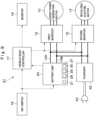
- the battery unit 20 is provided with a plurality of cells 22A to 22N as an example .
- the number of the cells may be two, or three or any number more than three.
- Fig. 3 shows the configuration of the battery unit 20.
- the battery unit 20 is provided with a storage battery 21, cell balancing circuits 23A to 23N, cell voltage detectors 24A to 24N, a total voltage detector 25, a current detector 26 and a battery controller 27.
- the storage battery 21 configures a first battery that supplies power to the assist power generation motor 10 as an electric motor.
- the storage battery 21 supplies the power to the revolving electric motor 14 as well.
- the storage battery 21 is configured of the plurality of cells 22A to 22N series-connected to each other.
- the storage battery 21 is a lithium-ion secondary battery, for example, and is an assembled battery configured of the plurality of cells 22A to 22N.
- the plurality of cells 22A to 22N hold electrical charges.
- a terminal 21A of the storage battery 21 at the positive electrode side is connected via a relay (not shown) to the DC bus 13A at the positive electrode side.
- a terminal 21B of the storage battery 21 at the negative electrode side is connected via a relay (not shown) to the DC bus 13B at the negative electrode side.
- the cell balancing circuit 23A is parallelly-connected to the cell 22A.
- the cell balancing circuit 23A adjusts a charging rate of the cell 22A in response to a signal of a balancing control section 28.
- the cell balancing circuit 23A is provided with a switch and a discharge resistance series-connected to each other (any of them is not shown).
- the switch of the cell balancing circuit 23A is normally in an off state (in an opened state) .
- the cell balancing circuit 23A turns on (closes) a switch SW based upon a command of the balancing control section 28.
- the cell balancing circuit 23A causes a current to the discharge resistance to discharge the cell 22A.
- the cell voltage detector 24A is connected to the cell 22A.
- the cell voltage detector 24A measures a cell voltage VcA applied to both ends of the cell 22A.
- the cell balancing circuits 23B to 23N and the cell voltage detectors 24B to 24N are connected, as similar to the cell 22A, to the cells 22B to 22N as well.
- the cell voltage detectors 24A to 24N detect cell voltages VcA to VcN of the plurality of cells 22A to 22N respectively.
- the total voltage detector 25 is connected to both ends of the storage battery 21.
- the total voltage detector 25 detects a total voltage value Vt of the series-connected cells 22A to 22N. At this time, the total voltage value Vt amounts to an additional value of all of the cell voltages VcA to VcN.
- the total voltage detector 25 outputs the detected total voltage value Vt to a charging rate calculating section 30 of the battery controller 27.
- the current detector 26 detects a current value I flowing in the cells 22A to 22N.
- the current detector 26 outputs the detected current value I to the charging rate calculating section 30 of the battery controller 27.
- the battery controller 27 controls the cell voltages VcA to VcN.
- the battery controller 27 receives power supplied from a lead battery 31 (a second battery) to execute the balancing control that reduces variation in the cell voltages VcA to VcN of the plurality of cells 22A to 22N.
- the battery controller 27 is configured of a microcomputer, for example.
- the battery controller 27 is provided with the balancing control section 28, a battery control section 29 and the charging rate calculating section 30.
- a program of the balancing control processing as shown in Fig. 4 and Fig. 5 is stored in a memory part (not shown) of the battery controller 27.
- the balancing control section 28 discharges cells high in the cell voltage based upon each of the cell voltages VcA to VcN detected by the cell voltage detectors 24A to 24N to control the cell balancing circuits 23A to 23N to equalize the cell voltage. Specifically, while the balancing command is outputted from the balancing control section 28, when a difference in voltage between the maximum cell voltage of the cell voltages VcA to VcN and the minimum cell voltage of the cell voltages VcA to VcN goes beyond a predetermined threshold value voltage, the balancing control section 28 executes the balancing control. As a result, the difference in voltage is suppressed to a value smaller than the threshold value voltage .
- the balancing control section 28 calculates a balancing required time Tb0 based upon the cell voltages VcA to VcN of the cell voltage detectors 24A to 24N in response to a balancing command from the battery control section 29.
- the balancing control section 28 controls the cell balancing circuits 23A to 23N and executes the balancing control in accordance with the balancing required time Tb0.
- the battery control section 29 outputs the balancing command to the balancing control section 28 to control start and stop of the balancing control by the balancing control section 28.
- the balancing control section 28, the key switch 16, the charging rate calculating section 30 and a lead battery monitoring section 34 are connected to the input side of the battery control section 29.
- the balancing control section 28, a second relay 33 and the vehicle body controller 17 are connected to the output side of the battery control section 29.
- the battery control section 29 executes the program of the balancing control processing as shown in Fig. 4 and Fig. 5 .
- the battery control section 29 outputs the balancing command when the key switch 16 is switched from an off state to an on state. Thereby, the battery control section 29 starts the balancing control.
- the battery control section 29 continues to output the balancing command to continuously execute the balancing control even when the key switch 16 is switched from the on state to the off state. Thereafter, the battery control section 29 stops the balancing control based upon the balancing required time Tb0 calculated by the balancing control section 28, the charging rate of the storage battery 21 calculated by the charging rate calculating section 30 and the voltage state of the lead battery 31 detected by the lead battery monitoring section 34.
- the battery control section 29 causes the balancing control section 28 to execute the balancing control in a time range during which the voltage of the lead battery 31 becomes equal to or more than a predetermined given voltage value V1 and the charging rate of the storage battery 21 becomes equal to or more than a predetermined given charging rate value SOC1 after the key switch 16 is switched from the on state (the drive position) to the off state (the stop position).
- the battery control section 29 is provided with a first time calculating section 29A that calculates a first balancing remaining time Tb3 (a first time) as a remaining time required until the balancing control is completed when the key switch 16 is switched from the on state to the off state, a second time calculating section 29B that calculates a first balancing possible time Tb4 (a second time) as a time during which the balancing control is possible based upon the voltage state of the lead battery 31, and a third time calculating section 29C that calculates a second balancing possible time Tb6 (a third time) as a time during which the balancing control is possible based upon the charging rate of the storage battery 21.
- a first time calculating section 29A that calculates a first balancing remaining time Tb3 (a first time) as a remaining time required until the balancing control is completed when the key switch 16 is switched from the on state to the off state
- a second time calculating section 29B that calculates a first balancing possible time T
- the battery control section 29 causes the balancing control section 28 to execute the balancing control by a minimum time (a second balancing limit time Tb7) out of the time calculated by the first time calculating section 29A, the time calculated by the second time calculating section 29B, and the time calculated by the third time calculating section 29C.
- a minimum time (a second balancing limit time Tb7) out of the time calculated by the first time calculating section 29A, the time calculated by the second time calculating section 29B, and the time calculated by the third time calculating section 29C.
- the battery control section 29 subtracts an elapse time (a continuation time Tb8) after the key switch 16 is switched from the on state to the off state from the minimum time (the second balancing limit time Tb7) to calculate a second balancing remaining time Tb9.
- the battery control section 29 outputs the second balancing remaining time Tb9 to the vehicle body controller 17.
- the vehicle body controller 17 outputs the second balancing remaining time Tb9 to the monitor 18.
- the battery control section 29 causes the monitor 18 to display the second balancing remaining time Tb9 as a remaining time of the balancing control.
- the input side of the charging rate calculating section 30 is connected to the total voltage detector 25 and the current detector 26.
- the output side of the charging rate calculating section 30 is connected to the battery control section 29.
- the charging rate calculating section 30 calculates the charging rate of the storage battery 21 based upon a total voltage value Vt detected by the total voltage detector 25 and a current value I detected by the current detector 26.
- the charging rate calculating section 30 outputs the charging rate of the storage battery 21 to the battery control section 29.
- the lead battery 31 configures a second battery that supplies driving power to the battery controller 27.
- the lead battery 31 supplies the power lower than the storage battery 21.
- the lead battery 31 is connected via a first relay 32 and the second relay 33 connected in parallel to each other to the battery controller 27.
- the first relay 32 is switched between an on state (a connection state) and an off state (a disconnection state) based upon a signal from the key switch 16.
- the first relay 32 is turned on when the key switch 16 is turned on (is turned to a drive position) .
- the first relay 32 is turned off when the key switch 16 is turned off (is turned to a stop position) .
- the second relay 33 is switched between an on state (a connection state) and an off state (a disconnection state) in response to a signal (a balancing command) from the battery control section 29.
- the second relay 33 is turned on when the battery control section 29 outputs the balancing command.
- the second relay 33 is turned off when the battery control section 29 stops the output of the balancing command.
- the second relay 33 is switched from the on state to the off state when the minimum time (the second balancing limit time Tb7) elapses from start of the output of the balancing command.
- the input side of the lead battery monitoring section 34 is connected to both ends of the lead battery 31.
- the output side of the lead battery monitoring section 34 is connected to the battery control section 29.
- the lead battery monitoring section 34 detects the voltage of the lead battery 31.
- the lead battery monitoring section 34 outputs the detected voltage value of the lead battery 31 to the battery control section 29.
- the input side of the vehicle body controller 17 is connected to the battery control section 29.
- the output side of the vehicle body controller 17 is connected to the monitor 18.
- Time information of the balancing control is inputted to the vehicle body controller 17 from the battery control section 29.
- the second balancing remaining time Tb9 is inputted to the vehicle body controller 17 as a remaining time of the balancing control after the key switch 16 is switched to the off state.
- the vehicle body controller 17 outputs the second balancing remaining time Tb9 to the monitor 18. Thereby, the monitor 18 displays the second balancing remaining time Tb9.
- the first relay 32 When the key switch 16 is turned on, the first relay 32 is turned on to activate the battery controller 27.
- the battery control section 29 executes the balancing control processing as shown in Fig. 4 and Fig. 5 .
- step S1 the second relay 33 is turned on.
- step S2 the balancing command is turned on, which is outputted to the balancing control section 28.
- the balancing control section 28 calculates the balancing required time Tb0 and starts the balancing control.
- the balancing required time Tb0 is the maximum value Tb1 of the time required for the variation in the charging rate of each of the cells 22A to 22N to be reduced to a tolerance range by the balancing control.
- the battery control section 29 obtains the maximum value Tb1 of the balancing required time Tb0 from the balancing control section 28.
- step S4 the balancing continuation time Tb2 after the key switch 16 is turned on is measured.
- step S5 the signal of the key switch 16 is determined, and the process goes back to step S4 while the key switch 16 is in the on state.
- the battery control section 29 determines the first balancing remaining time Tb3. In a case where the first balancing remaining time Tb3 is equal to or less than 0 (Tb3 ⁇ 0), in step S7 "YES" is determined, and the process goes to step S16.
- step S7 "NO" is determined, and the process goes to step S8.
- step S8 the voltage state of the lead battery 31 is obtained from the lead battery monitoring section 34, and the first balancing possible time Tb4 is calculated based upon the voltage state of the lead battery 31.
- the first balancing possible time Tb4 is a time during which it is possible to keep the voltage of the lead battery 31 to be equal to or more than the given voltage value V1 even when the balancing control continues to be executed in a state where the key switch 16 is in the off state.
- the given voltage value V1 is a voltage in which the engine 7 can be activated using the lead battery 31 when the key switch 16 is switched to the on state next time, for example. That is, the given voltage value V1 is a voltage in which it is possible to drive a starter motor of the engine 7 (not shown) using the lead battery 31, for example.
- step S10 the charging rate of the storage battery 21 is obtained from the charging rate calculating section 30, and the second balancing possible time Tb6 is calculated based upon the charging rate of the storage battery 21.
- the second balancing possible time Tb6 is a time during which it is possible to keep the charging rate of the storage battery 21 to be equal to or more than the given charging rate value SOC1 even when the balancing control continues to be executed in a state where the key switch 16 is in the off state.
- the given charging rate value SOC1 of the charging rate is, for example, a lower limit value (for example, approximately 30%) in an appropriate use range (for example, 70% to 30%) of the charging rate.
- step S12 the balancing continuation time Tb8 is measured after the key switch 16 is switched from the on state to the off state.
- the balancing continuation time Tb8 is a time during which the balancing control continues to be executed after the key switch 16 is switched from the on state to the off state.
- step S14 the battery control section 29 outputs the second balancing remaining time Tb9 to the vehicle body controller 17. Thereby, the vehicle body controller 17 causes the monitor 18 to display the second balancing remaining time Tb9.
- step S15 the battery control section 29 determines the second balancing remaining time Tb9.
- the second balancing remaining time Tb9 is larger than 0 (Tb9 > 0)
- step S15 "NO” is determined, and the process goes back to step S12.
- step S15 "YES” is determined, and the process goes to step S16.
- step S16 the balancing command outputted from the step S2 is turned off.
- step S17 the second relay 33 is turned off to stop the battery controller 27.
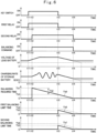
- Fig. 6 to Fig. 8 show a time change in the key switch 16, the first relay 32, the second relay 33, the balancing command, the voltage of the lead battery 31, the charging rate of the storage battery 21, the balancing required time, the first balancing limit time, and the second balancing limit time.
- the key switch 16 is switched from the off state to the on state, and the first relay 32 is turned on.
- the power is supplied to the battery controller 27 from the lead battery 31 to activate the battery controller 27.
- the battery control section 29 outputs a signal to the second relay 33 to turn on the second relay 33.
- the battery control section 29 outputs the balancing command in the on state to the balancing control section 28.
- the balancing control section 28 calculates the balancing required time Tb0, and transmits the balancing required time Tb0 as the maximum value Tb1 to the battery control section 29.
- the balancing control of the cells 22A to 22N is executed and the balancing continuation time Tb2 is measured during a period where the key switch 16 is kept in the on state.
- the key switch 16 is switched from the on state to the off state, and thereby, the first relay 32 is turned off. Meanwhile, since the second relay 33 is in the on state, the battery controller 27 continues to be activated. At this time, the battery control section 29 subtracts the balancing continuation time Tb2 from the maximum value Tb1 of the balancing required time Tb0 to calculate the first balancing remaining time Tb3. The battery control section 29 determines whether or not the first balancing remaining time Tb3 is equal to or less than 0 . At time t13, the first balancing remaining time Tb3 is larger than 0.
- the battery control section 29 calculates the first balancing possible time Tb4 from the voltage state of the lead battery 31. At this time, since the voltage of the lead battery 31 is sufficiently higher than the given voltage value V1, the first balancing possible time Tb4 is made long. At time t13, when the first balancing possible time Tb4 and the first balancing remaining time Tb3 are compared, the first balancing remaining time Tb3 is shorter. Therefore, the first balancing limit time Tb5 becomes equal to the first balancing remaining time Tb3.
- the battery control section 29 calculates the second balancing possible time Tb6 from the charging rate of the storage battery 21. At this time, since the charging rate of the storage battery 21 is sufficiently higher than the given charging rate value SOC1, the second balancing possible time Tb6 is made long. At time t13, when the second balancing possible time Tb6 and the first balancing limit time Tb5 are compared, the first balancing limit time Tb5 is shorter. Therefore, the second balancing limit time Tb7 becomes equal to the first balancing limit time Tb5. Thereby, the second balancing limit time Tb7 becomes the same value as the first balancing remaining time Tb3.
- the battery control section 29 subtracts the balancing continuation time Tb8 after the key switch 16 is turned off from the second balancing limit time Tb7 to calculate the second balancing remaining time Tb9.
- the battery control section 29 executes the balancing control of the cells 22A to 22N during a period until the second balancing remaining time Tb9 becomes equal to 0.
- the second balancing remaining time Tb9 becomes equal to 0.
- the battery control section 29 turns off the balancing command.
- the battery control section 29 turns off the second relay 33. Thereby, the battery controller 27 is stopped.
- the balancing control of the cells 22A to 22N is executed until the completion. Thereby, it is possible to equalize the charging rate between the cells 22A to 22N in the storage battery 21.
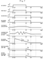
- the battery control section 29 calculates the second balancing possible time Tb6 based upon the charging rate of the storage battery 21. At this time, since the charging rate of the storage battery 21 is in a sufficiently high state, the second balancing possible time Tb6 is longer than the first balancing possible time Tb4. Accordingly, when the second balancing possible time Tb6 and the first balancing limit time Tb5 are compared, the first balancing limit time Tb5 is shorter. Therefore, the second balancing limit time Tb7 becomes equal to the first balancing limit time Tb5. Thereby, the second balancing limit time Tb7 becomes the same value as the first balancing possible time Tb4.
- the second balancing remaining time Tb9 becomes equal to 0, and the first balancing possible time Tb4 becomes equal to 0. That is, even when the balancing control continues to be executed in a state where the key switch 16 is in the off state, the balancing control is executed by the upper limit time during which it is possible to keep the voltage of the lead battery 31 to be equal to or more than the given voltage value V1.
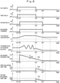
- the second balancing remaining time Tb9 becomes equal to 0, and the second balancing possible time Tb6 becomes equal to 0. That is, even when the balancing control continues to be executed in a state where the key switch 16 is in the off state, the balancing control is executed by the upper limit time during which it is possible to keep the charging rate of the storage battery 21 to be equal to or more than the given charging rate value SOC1.
- the battery controller 27 executes the balancing control in a time range during which the voltage of the lead battery 31 becomes equal to or more than the predetermined given voltage value V1 and the charging rate of the storage battery 21 becomes equal to or more than the predetermined given charging rate value SOC1 after the key switch 16 is switched from the on state (the drive position) to the off state (the stop position).
- the battery controller 27 calculates the first balancing remaining time Tb3 (the first time) as a remaining time required until the balancing control is completed when the key switch 16 is switched from the on state to the off state, calculates the first balancing possible time Tb4 (the second time) as a time during which the balancing control is possible based upon the voltage state of the lead battery 31, and calculates the second balancing possible time Tb6 (the third time) as a time during which the balancing control is possible based upon the charging rate of the storage battery 21.
- the battery controller 27 executes the balancing control by the minimum time (the second balancing limit time Tb7) out of the first balancing remaining time Tb3 (the first time), the first balancing possible time Tb4 (the second time) and the second balancing possible time Tb6 (the third time).
- the balancing control is executed in a state where the key switch 16 is in the off state, the voltage of the lead battery 31 is kept to be equal to or more than the given voltage value V1 required for the next activation of the vehicle body.
- the charging rate of the storage battery 21 is kept to be equal to or more than the given charging rate value SOC1 required for the next activation of the vehicle body. As a result, it is possible to equalize the charging rate between the cells 22A to 22N in consideration of a state of the storage battery 21 and the lead battery 31 preventing the activation of the vehicle body from being affected.
- the battery controller 27 subtracts the elapse time (the balancing continuation time Tb8) after the key switch 16 is switched from the on state (the drive position) to the off state (the stop position) from the minimum time (the second balancing limit time Tb7) during which the balancing control is executed, and causes the monitor 18 to display the remaining time (the second balancing remaining time Tb9) of the balancing control. Therefore, an operator can recognize the remaining time when the balancing control is executed after the key switch 16 is turned to the off state, by looking at the monitor 18 visually.
- the lead battery 31 is connected via the first relay 32 and the second relay 33 parallelly connected to each other to the battery controller 27.
- the first relay 32 is turned to the on state (the connection state) when the key switch 16 is switched to the on state (the drive position), and is turned to the off state (the disconnection state) when the key switch 16 is switched to the off state (the stop position).
- the second relay 33 is turned to the on state (the connection state) when the battery controller 27 executes the balancing control, and is turned to the off state (the disconnection) when the second balancing limit time Tb7 (the minimum time) elapses from a point where the balancing control starts.
- the battery control section 29 can cause the balancing control section 28 to continue to execute the balancing control even after the key switch 16 is switched to the off state.
- the battery unit 20 is provided with the single series circuit in which the cells 22A to 22N are series-connected is explained as an example.
- the present invention is not limited thereto, but, for example, an electricity storage device may be configured such that there are provided a plurality of series circuits in which a plurality of cells are series-connected and these series circuits are parallelly connected.
- the hybrid hydraulic excavator 1 provided with the engine 7, the assist power generation motor 10 and the battery unit 20 is explained as an example.
- the present invention is not limited thereto, but may be, as a modification example in Fig. 9 , applied to an electric hydraulic excavator 41.
- the hydraulic excavator 41 is provided with a charger 42 for charging the battery unit 20 from an exterior with an engine removed.
- the charger 42 is connected to the DC buses 13A, 13B.
- the charger 42 has an external power source connecting terminal 43 for connection to an external power source such as a commercial power source.
- the charger 42 supplies power supplied from the external power source connecting terminal 43 to the battery unit 20 to charge the storage battery 21 in the battery unit 20.
- the battery control section 29 in the battery controller 27 calculates the first balancing possible time Tb4 based upon the voltage of the lead battery 31.
- the first balancing possible time Tb4 is a time during which the voltage of the lead battery 31 can be kept to be equal to or more than the given voltage value V1 even when the balancing control continues to be executed in a case where the key switch 16 is in the off state.
- the given voltage value V1 is a voltage with which the activation of the battery controller 27 is made possible using the lead battery 31 when the key switch 16 is turned to the on state the next time, for example.
- the storage battery 21 composed of the lithium-ion secondary battery is explained as an example of the first battery.
- the present invention is not limited thereto, but the first battery may be a secondary battery composed of another material or may be a capacitor.
- the lead battery is explained as an example of the second battery.
- the present invention is not limited thereto, but the second battery may be a lithium-ion secondary battery or a secondary battery composed of another material.
- the assist power generation motor 10 and the revolving electric motor 14 are connected to the battery unit 20.
- the present invention is not limited thereto, but only the assist power generation motor 10 may be connected to the battery unit 20 with the revolving electric motor 14 removed.
- the hydraulic excavator 1 is explained as an example of the construction machine.
- the present invention is not limited thereto, but may be applied to various construction machines such as a wheel loader.
Landscapes
- Engineering & Computer Science (AREA)
- Power Engineering (AREA)
- Mechanical Engineering (AREA)
- Transportation (AREA)
- Sustainable Energy (AREA)
- Sustainable Development (AREA)
- Life Sciences & Earth Sciences (AREA)
- Electrochemistry (AREA)
- General Chemical & Material Sciences (AREA)
- Chemical Kinetics & Catalysis (AREA)
- Chemical & Material Sciences (AREA)
- Manufacturing & Machinery (AREA)
- Civil Engineering (AREA)
- General Engineering & Computer Science (AREA)
- Structural Engineering (AREA)
- Mining & Mineral Resources (AREA)
- Charge And Discharge Circuits For Batteries Or The Like (AREA)
- Electric Propulsion And Braking For Vehicles (AREA)
- Secondary Cells (AREA)
Applications Claiming Priority (2)
| Application Number | Priority Date | Filing Date | Title |
|---|---|---|---|
| JP2018046593A JP6993911B2 (ja) | 2018-03-14 | 2018-03-14 | 建設機械 |
| PCT/JP2019/004441 WO2019176392A1 (ja) | 2018-03-14 | 2019-02-07 | 建設機械 |
Publications (3)
| Publication Number | Publication Date |
|---|---|
| EP3767786A1 EP3767786A1 (en) | 2021-01-20 |
| EP3767786A4 EP3767786A4 (en) | 2021-12-15 |
| EP3767786B1 true EP3767786B1 (en) | 2024-12-25 |
Family
ID=67907653
Family Applications (1)
| Application Number | Title | Priority Date | Filing Date |
|---|---|---|---|
| EP19767991.3A Active EP3767786B1 (en) | 2018-03-14 | 2019-02-07 | Construction equipment |
Country Status (6)
Families Citing this family (5)
| Publication number | Priority date | Publication date | Assignee | Title |
|---|---|---|---|---|
| WO2021173951A1 (en) * | 2020-02-27 | 2021-09-02 | Cnh Industrial America Llc | An electric work vehicle having an electric drivetrain and storage component configuration |
| JP2023139914A (ja) * | 2022-03-22 | 2023-10-04 | 日立建機株式会社 | 建設機械 |
| JP2024044437A (ja) | 2022-09-21 | 2024-04-02 | ヤンマーホールディングス株式会社 | 制御装置 |
| EP4557562A4 (en) * | 2023-02-27 | 2025-08-06 | Huawei Digital Power Tech Co Ltd | BATTERY BALANCING CIRCUIT, ENERGY STORAGE DEVICE AND ENERGY STORAGE SYSTEM AND BALANCING CONTROL METHOD THEREFOR |
| US20250109572A1 (en) * | 2023-09-29 | 2025-04-03 | Caterpillar Inc. | Hot swappable battery configuration |
Citations (1)
| Publication number | Priority date | Publication date | Assignee | Title |
|---|---|---|---|---|
| US20120161708A1 (en) * | 2010-12-22 | 2012-06-28 | Hitachi Vehicle Energy, Ltd. | Cell Control Device and Electricity Storage Device Incorporating the Same |
Family Cites Families (13)
| Publication number | Priority date | Publication date | Assignee | Title |
|---|---|---|---|---|
| JPS5831376B2 (ja) | 1981-04-11 | 1983-07-05 | 住友金属工業株式会社 | 焼結原料の装入方法およびその装置 |
| US8100210B2 (en) | 2006-02-07 | 2012-01-24 | Takeuchi Mfg. Co., Ltd | Electrically driven industrial vehicle |
| JP5127383B2 (ja) | 2007-09-28 | 2013-01-23 | 株式会社日立製作所 | 電池用集積回路および該電池用集積回路を使用した車両用電源システム |
| CN101318489B (zh) * | 2008-05-07 | 2011-09-21 | 中国科学院电工研究所 | 车载电池管理系统控制方法 |
| JP5567956B2 (ja) * | 2010-09-16 | 2014-08-06 | 矢崎総業株式会社 | 複数組電池のセル電圧均等化装置 |
| JP5831376B2 (ja) | 2012-07-11 | 2015-12-09 | 株式会社デンソー | 組電池の制御装置 |
| JP6290092B2 (ja) | 2012-10-10 | 2018-03-07 | 住友建機株式会社 | ショベル |
| US9825477B2 (en) | 2012-10-19 | 2017-11-21 | Hitachi Automotive Systems, Ltd. | Assembled battery monitoring device |
| JP6150821B2 (ja) * | 2013-02-08 | 2017-06-21 | 住友建機株式会社 | ショベル及びショベルの制御方法 |
| JP6430100B2 (ja) | 2013-03-21 | 2018-11-28 | 住友建機株式会社 | ショベル |
| CN107107764B (zh) * | 2014-12-15 | 2020-08-14 | 沃尔沃卡车集团 | 用于对车辆中的电能存储系统充电的方法和装置 |
| JP6361643B2 (ja) | 2015-12-15 | 2018-07-25 | 横河電機株式会社 | 蓄電サービスシステム |
| JP7082755B2 (ja) * | 2018-02-15 | 2022-06-09 | 株式会社ジェイテクト | 電源装置 |
-
2018
- 2018-03-14 JP JP2018046593A patent/JP6993911B2/ja active Active
-
2019
- 2019-02-07 KR KR1020207005787A patent/KR102335839B1/ko active Active
- 2019-02-07 EP EP19767991.3A patent/EP3767786B1/en active Active
- 2019-02-07 WO PCT/JP2019/004441 patent/WO2019176392A1/ja unknown
- 2019-02-07 US US16/644,409 patent/US11085172B2/en active Active
- 2019-02-07 CN CN201980004179.9A patent/CN111052534B/zh active Active
Patent Citations (1)
| Publication number | Priority date | Publication date | Assignee | Title |
|---|---|---|---|---|
| US20120161708A1 (en) * | 2010-12-22 | 2012-06-28 | Hitachi Vehicle Energy, Ltd. | Cell Control Device and Electricity Storage Device Incorporating the Same |
Also Published As
| Publication number | Publication date |
|---|---|
| CN111052534A (zh) | 2020-04-21 |
| EP3767786A1 (en) | 2021-01-20 |
| US11085172B2 (en) | 2021-08-10 |
| JP6993911B2 (ja) | 2022-02-03 |
| US20200199848A1 (en) | 2020-06-25 |
| KR102335839B1 (ko) | 2021-12-07 |
| KR20200035998A (ko) | 2020-04-06 |
| CN111052534B (zh) | 2023-06-16 |
| JP2019161888A (ja) | 2019-09-19 |
| WO2019176392A1 (ja) | 2019-09-19 |
| EP3767786A4 (en) | 2021-12-15 |
Similar Documents
| Publication | Publication Date | Title |
|---|---|---|
| EP3767786B1 (en) | Construction equipment | |
| US9290904B2 (en) | Shovel and method of controlling shovel | |
| JP5225779B2 (ja) | 充放電制御方法 | |
| KR101888044B1 (ko) | 쇼벨 및 쇼벨의 제어방법 | |
| JP6150821B2 (ja) | ショベル及びショベルの制御方法 | |
| US9982416B2 (en) | Shovel and method of controlling shovel | |
| CN112514195B (zh) | 工程机械 | |
| KR102243723B1 (ko) | 건설 기계 | |
| US9725880B2 (en) | Apparatus for controlling a cascaded hybrid construction machine system and a method therefor | |
| JP2015070690A (ja) | 作業機械駆動用蓄電装置の充電装置及び充電方法 | |
| JP6000883B2 (ja) | ショベル | |
| JP6430100B2 (ja) | ショベル |
Legal Events
| Date | Code | Title | Description |
|---|---|---|---|
| STAA | Information on the status of an ep patent application or granted ep patent |
Free format text: STATUS: THE INTERNATIONAL PUBLICATION HAS BEEN MADE |
|
| PUAI | Public reference made under article 153(3) epc to a published international application that has entered the european phase |
Free format text: ORIGINAL CODE: 0009012 |
|
| STAA | Information on the status of an ep patent application or granted ep patent |
Free format text: STATUS: REQUEST FOR EXAMINATION WAS MADE |
|
| 17P | Request for examination filed |
Effective date: 20201014 |
|
| AK | Designated contracting states |
Kind code of ref document: A1 Designated state(s): AL AT BE BG CH CY CZ DE DK EE ES FI FR GB GR HR HU IE IS IT LI LT LU LV MC MK MT NL NO PL PT RO RS SE SI SK SM TR |
|
| AX | Request for extension of the european patent |
Extension state: BA ME |
|
| DAV | Request for validation of the european patent (deleted) | ||
| DAX | Request for extension of the european patent (deleted) | ||
| A4 | Supplementary search report drawn up and despatched |
Effective date: 20211116 |
|
| RIC1 | Information provided on ipc code assigned before grant |
Ipc: H02J 7/00 20060101ALI20211110BHEP Ipc: H01M 10/48 20060101ALI20211110BHEP Ipc: H01M 10/44 20060101ALI20211110BHEP Ipc: B60L 58/00 20190101ALI20211110BHEP Ipc: B60L 55/00 20190101ALI20211110BHEP Ipc: B60L 53/00 20190101ALI20211110BHEP Ipc: B60L 50/50 20190101ALI20211110BHEP Ipc: B60L 50/40 20190101ALI20211110BHEP Ipc: H02J 7/02 20160101AFI20211110BHEP |
|
| GRAP | Despatch of communication of intention to grant a patent |
Free format text: ORIGINAL CODE: EPIDOSNIGR1 |
|
| STAA | Information on the status of an ep patent application or granted ep patent |
Free format text: STATUS: GRANT OF PATENT IS INTENDED |
|
| INTG | Intention to grant announced |
Effective date: 20240717 |
|
| GRAS | Grant fee paid |
Free format text: ORIGINAL CODE: EPIDOSNIGR3 |
|
| GRAA | (expected) grant |
Free format text: ORIGINAL CODE: 0009210 |
|
| STAA | Information on the status of an ep patent application or granted ep patent |
Free format text: STATUS: THE PATENT HAS BEEN GRANTED |
|
| AK | Designated contracting states |
Kind code of ref document: B1 Designated state(s): AL AT BE BG CH CY CZ DE DK EE ES FI FR GB GR HR HU IE IS IT LI LT LU LV MC MK MT NL NO PL PT RO RS SE SI SK SM TR |
|
| REG | Reference to a national code |
Ref country code: GB Ref legal event code: FG4D |
|
| REG | Reference to a national code |
Ref country code: CH Ref legal event code: EP |
|
| REG | Reference to a national code |
Ref country code: DE Ref legal event code: R096 Ref document number: 602019063972 Country of ref document: DE |
|
| REG | Reference to a national code |
Ref country code: IE Ref legal event code: FG4D |
|
| REG | Reference to a national code |
Ref country code: LT Ref legal event code: MG9D |
|
| PG25 | Lapsed in a contracting state [announced via postgrant information from national office to epo] |
Ref country code: HR Free format text: LAPSE BECAUSE OF FAILURE TO SUBMIT A TRANSLATION OF THE DESCRIPTION OR TO PAY THE FEE WITHIN THE PRESCRIBED TIME-LIMIT Effective date: 20241225 |
|
| PGFP | Annual fee paid to national office [announced via postgrant information from national office to epo] |
Ref country code: DE Payment date: 20250228 Year of fee payment: 7 |
|
| PG25 | Lapsed in a contracting state [announced via postgrant information from national office to epo] |
Ref country code: FI Free format text: LAPSE BECAUSE OF FAILURE TO SUBMIT A TRANSLATION OF THE DESCRIPTION OR TO PAY THE FEE WITHIN THE PRESCRIBED TIME-LIMIT Effective date: 20241225 |
|
| PG25 | Lapsed in a contracting state [announced via postgrant information from national office to epo] |
Ref country code: BG Free format text: LAPSE BECAUSE OF FAILURE TO SUBMIT A TRANSLATION OF THE DESCRIPTION OR TO PAY THE FEE WITHIN THE PRESCRIBED TIME-LIMIT Effective date: 20241225 |
|
| PG25 | Lapsed in a contracting state [announced via postgrant information from national office to epo] |
Ref country code: NO Free format text: LAPSE BECAUSE OF FAILURE TO SUBMIT A TRANSLATION OF THE DESCRIPTION OR TO PAY THE FEE WITHIN THE PRESCRIBED TIME-LIMIT Effective date: 20250325 |
|
| PG25 | Lapsed in a contracting state [announced via postgrant information from national office to epo] |
Ref country code: LV Free format text: LAPSE BECAUSE OF FAILURE TO SUBMIT A TRANSLATION OF THE DESCRIPTION OR TO PAY THE FEE WITHIN THE PRESCRIBED TIME-LIMIT Effective date: 20241225 Ref country code: GR Free format text: LAPSE BECAUSE OF FAILURE TO SUBMIT A TRANSLATION OF THE DESCRIPTION OR TO PAY THE FEE WITHIN THE PRESCRIBED TIME-LIMIT Effective date: 20250326 |
|
| PGFP | Annual fee paid to national office [announced via postgrant information from national office to epo] |
Ref country code: GB Payment date: 20250220 Year of fee payment: 7 |
|
| PG25 | Lapsed in a contracting state [announced via postgrant information from national office to epo] |
Ref country code: RS Free format text: LAPSE BECAUSE OF FAILURE TO SUBMIT A TRANSLATION OF THE DESCRIPTION OR TO PAY THE FEE WITHIN THE PRESCRIBED TIME-LIMIT Effective date: 20250325 |
|
| REG | Reference to a national code |
Ref country code: NL Ref legal event code: MP Effective date: 20241225 |
|
| PG25 | Lapsed in a contracting state [announced via postgrant information from national office to epo] |
Ref country code: NL Free format text: LAPSE BECAUSE OF FAILURE TO SUBMIT A TRANSLATION OF THE DESCRIPTION OR TO PAY THE FEE WITHIN THE PRESCRIBED TIME-LIMIT Effective date: 20241225 |
|
| REG | Reference to a national code |
Ref country code: AT Ref legal event code: MK05 Ref document number: 1755015 Country of ref document: AT Kind code of ref document: T Effective date: 20241225 |
|
| PG25 | Lapsed in a contracting state [announced via postgrant information from national office to epo] |
Ref country code: SM Free format text: LAPSE BECAUSE OF FAILURE TO SUBMIT A TRANSLATION OF THE DESCRIPTION OR TO PAY THE FEE WITHIN THE PRESCRIBED TIME-LIMIT Effective date: 20241225 |
|
| PG25 | Lapsed in a contracting state [announced via postgrant information from national office to epo] |
Ref country code: PL Free format text: LAPSE BECAUSE OF FAILURE TO SUBMIT A TRANSLATION OF THE DESCRIPTION OR TO PAY THE FEE WITHIN THE PRESCRIBED TIME-LIMIT Effective date: 20241225 |
|
| PG25 | Lapsed in a contracting state [announced via postgrant information from national office to epo] |
Ref country code: ES Free format text: LAPSE BECAUSE OF FAILURE TO SUBMIT A TRANSLATION OF THE DESCRIPTION OR TO PAY THE FEE WITHIN THE PRESCRIBED TIME-LIMIT Effective date: 20241225 |
|
| PG25 | Lapsed in a contracting state [announced via postgrant information from national office to epo] |
Ref country code: IS Free format text: LAPSE BECAUSE OF FAILURE TO SUBMIT A TRANSLATION OF THE DESCRIPTION OR TO PAY THE FEE WITHIN THE PRESCRIBED TIME-LIMIT Effective date: 20250425 |
|
| PG25 | Lapsed in a contracting state [announced via postgrant information from national office to epo] |
Ref country code: PT Free format text: LAPSE BECAUSE OF FAILURE TO SUBMIT A TRANSLATION OF THE DESCRIPTION OR TO PAY THE FEE WITHIN THE PRESCRIBED TIME-LIMIT Effective date: 20250428 |
|
| PG25 | Lapsed in a contracting state [announced via postgrant information from national office to epo] |
Ref country code: EE Free format text: LAPSE BECAUSE OF FAILURE TO SUBMIT A TRANSLATION OF THE DESCRIPTION OR TO PAY THE FEE WITHIN THE PRESCRIBED TIME-LIMIT Effective date: 20241225 |
|
| PG25 | Lapsed in a contracting state [announced via postgrant information from national office to epo] |
Ref country code: AT Free format text: LAPSE BECAUSE OF FAILURE TO SUBMIT A TRANSLATION OF THE DESCRIPTION OR TO PAY THE FEE WITHIN THE PRESCRIBED TIME-LIMIT Effective date: 20241225 Ref country code: RO Free format text: LAPSE BECAUSE OF FAILURE TO SUBMIT A TRANSLATION OF THE DESCRIPTION OR TO PAY THE FEE WITHIN THE PRESCRIBED TIME-LIMIT Effective date: 20241225 |
|
| PG25 | Lapsed in a contracting state [announced via postgrant information from national office to epo] |
Ref country code: SK Free format text: LAPSE BECAUSE OF FAILURE TO SUBMIT A TRANSLATION OF THE DESCRIPTION OR TO PAY THE FEE WITHIN THE PRESCRIBED TIME-LIMIT Effective date: 20241225 |
|
| PG25 | Lapsed in a contracting state [announced via postgrant information from national office to epo] |
Ref country code: CZ Free format text: LAPSE BECAUSE OF FAILURE TO SUBMIT A TRANSLATION OF THE DESCRIPTION OR TO PAY THE FEE WITHIN THE PRESCRIBED TIME-LIMIT Effective date: 20241225 |
|
| PG25 | Lapsed in a contracting state [announced via postgrant information from national office to epo] |
Ref country code: IT Free format text: LAPSE BECAUSE OF FAILURE TO SUBMIT A TRANSLATION OF THE DESCRIPTION OR TO PAY THE FEE WITHIN THE PRESCRIBED TIME-LIMIT Effective date: 20241225 |