EP3767407A1 - Dispositif, procédé et programme de commande - Google Patents
Dispositif, procédé et programme de commande Download PDFInfo
- Publication number
- EP3767407A1 EP3767407A1 EP19766943.5A EP19766943A EP3767407A1 EP 3767407 A1 EP3767407 A1 EP 3767407A1 EP 19766943 A EP19766943 A EP 19766943A EP 3767407 A1 EP3767407 A1 EP 3767407A1
- Authority
- EP
- European Patent Office
- Prior art keywords
- propagation delay
- data
- field network
- communication
- delay time
- Prior art date
- Legal status (The legal status is an assumption and is not a legal conclusion. Google has not performed a legal analysis and makes no representation as to the accuracy of the status listed.)
- Granted
Links
- 238000000034 method Methods 0.000 title claims description 29
- 238000004891 communication Methods 0.000 claims abstract description 77
- 238000005259 measurement Methods 0.000 claims abstract description 63
- 125000004122 cyclic group Chemical group 0.000 claims abstract description 8
- 238000001514 detection method Methods 0.000 claims abstract description 6
- 238000003745 diagnosis Methods 0.000 claims description 42
- 238000012544 monitoring process Methods 0.000 claims description 11
- 238000012545 processing Methods 0.000 claims description 9
- 230000005540 biological transmission Effects 0.000 description 12
- 238000010586 diagram Methods 0.000 description 11
- 230000005856 abnormality Effects 0.000 description 2
- 238000005516 engineering process Methods 0.000 description 2
- 230000004044 response Effects 0.000 description 2
- 230000010485 coping Effects 0.000 description 1
- 230000000694 effects Effects 0.000 description 1
Images
Classifications
-
- G—PHYSICS
- G05—CONTROLLING; REGULATING
- G05B—CONTROL OR REGULATING SYSTEMS IN GENERAL; FUNCTIONAL ELEMENTS OF SUCH SYSTEMS; MONITORING OR TESTING ARRANGEMENTS FOR SUCH SYSTEMS OR ELEMENTS
- G05B19/00—Programme-control systems
- G05B19/02—Programme-control systems electric
- G05B19/04—Programme control other than numerical control, i.e. in sequence controllers or logic controllers
- G05B19/042—Programme control other than numerical control, i.e. in sequence controllers or logic controllers using digital processors
-
- G—PHYSICS
- G05—CONTROLLING; REGULATING
- G05B—CONTROL OR REGULATING SYSTEMS IN GENERAL; FUNCTIONAL ELEMENTS OF SUCH SYSTEMS; MONITORING OR TESTING ARRANGEMENTS FOR SUCH SYSTEMS OR ELEMENTS
- G05B19/00—Programme-control systems
- G05B19/02—Programme-control systems electric
- G05B19/418—Total factory control, i.e. centrally controlling a plurality of machines, e.g. direct or distributed numerical control [DNC], flexible manufacturing systems [FMS], integrated manufacturing systems [IMS] or computer integrated manufacturing [CIM]
- G05B19/4185—Total factory control, i.e. centrally controlling a plurality of machines, e.g. direct or distributed numerical control [DNC], flexible manufacturing systems [FMS], integrated manufacturing systems [IMS] or computer integrated manufacturing [CIM] characterised by the network communication
- G05B19/4186—Total factory control, i.e. centrally controlling a plurality of machines, e.g. direct or distributed numerical control [DNC], flexible manufacturing systems [FMS], integrated manufacturing systems [IMS] or computer integrated manufacturing [CIM] characterised by the network communication by protocol, e.g. MAP, TOP
-
- H—ELECTRICITY
- H04—ELECTRIC COMMUNICATION TECHNIQUE
- H04L—TRANSMISSION OF DIGITAL INFORMATION, e.g. TELEGRAPHIC COMMUNICATION
- H04L12/00—Data switching networks
- H04L12/28—Data switching networks characterised by path configuration, e.g. LAN [Local Area Networks] or WAN [Wide Area Networks]
- H04L12/40—Bus networks
- H04L12/40006—Architecture of a communication node
- H04L12/40019—Details regarding a bus master
-
- H—ELECTRICITY
- H04—ELECTRIC COMMUNICATION TECHNIQUE
- H04L—TRANSMISSION OF DIGITAL INFORMATION, e.g. TELEGRAPHIC COMMUNICATION
- H04L12/00—Data switching networks
- H04L12/28—Data switching networks characterised by path configuration, e.g. LAN [Local Area Networks] or WAN [Wide Area Networks]
- H04L12/40—Bus networks
- H04L12/40169—Flexible bus arrangements
-
- H—ELECTRICITY
- H04—ELECTRIC COMMUNICATION TECHNIQUE
- H04L—TRANSMISSION OF DIGITAL INFORMATION, e.g. TELEGRAPHIC COMMUNICATION
- H04L43/00—Arrangements for monitoring or testing data switching networks
- H04L43/08—Monitoring or testing based on specific metrics, e.g. QoS, energy consumption or environmental parameters
- H04L43/0805—Monitoring or testing based on specific metrics, e.g. QoS, energy consumption or environmental parameters by checking availability
- H04L43/0817—Monitoring or testing based on specific metrics, e.g. QoS, energy consumption or environmental parameters by checking availability by checking functioning
-
- H—ELECTRICITY
- H04—ELECTRIC COMMUNICATION TECHNIQUE
- H04L—TRANSMISSION OF DIGITAL INFORMATION, e.g. TELEGRAPHIC COMMUNICATION
- H04L43/00—Arrangements for monitoring or testing data switching networks
- H04L43/08—Monitoring or testing based on specific metrics, e.g. QoS, energy consumption or environmental parameters
- H04L43/0852—Delays
-
- H—ELECTRICITY
- H04—ELECTRIC COMMUNICATION TECHNIQUE
- H04L—TRANSMISSION OF DIGITAL INFORMATION, e.g. TELEGRAPHIC COMMUNICATION
- H04L69/00—Network arrangements, protocols or services independent of the application payload and not provided for in the other groups of this subclass
- H04L69/40—Network arrangements, protocols or services independent of the application payload and not provided for in the other groups of this subclass for recovering from a failure of a protocol instance or entity, e.g. service redundancy protocols, protocol state redundancy or protocol service redirection
-
- G—PHYSICS
- G05—CONTROLLING; REGULATING
- G05B—CONTROL OR REGULATING SYSTEMS IN GENERAL; FUNCTIONAL ELEMENTS OF SUCH SYSTEMS; MONITORING OR TESTING ARRANGEMENTS FOR SUCH SYSTEMS OR ELEMENTS
- G05B2219/00—Program-control systems
- G05B2219/30—Nc systems
- G05B2219/31—From computer integrated manufacturing till monitoring
- G05B2219/31135—Fieldbus
-
- G—PHYSICS
- G05—CONTROLLING; REGULATING
- G05B—CONTROL OR REGULATING SYSTEMS IN GENERAL; FUNCTIONAL ELEMENTS OF SUCH SYSTEMS; MONITORING OR TESTING ARRANGEMENTS FOR SUCH SYSTEMS OR ELEMENTS
- G05B2219/00—Program-control systems
- G05B2219/30—Nc systems
- G05B2219/33—Director till display
- G05B2219/33342—Master slave, supervisor, front end and slave processor, hierarchical structure
-
- G—PHYSICS
- G05—CONTROLLING; REGULATING
- G05B—CONTROL OR REGULATING SYSTEMS IN GENERAL; FUNCTIONAL ELEMENTS OF SUCH SYSTEMS; MONITORING OR TESTING ARRANGEMENTS FOR SUCH SYSTEMS OR ELEMENTS
- G05B2219/00—Program-control systems
- G05B2219/30—Nc systems
- G05B2219/34—Director, elements to supervisory
- G05B2219/34279—Pc, personal computer as controller
-
- H—ELECTRICITY
- H04—ELECTRIC COMMUNICATION TECHNIQUE
- H04L—TRANSMISSION OF DIGITAL INFORMATION, e.g. TELEGRAPHIC COMMUNICATION
- H04L12/00—Data switching networks
- H04L12/28—Data switching networks characterised by path configuration, e.g. LAN [Local Area Networks] or WAN [Wide Area Networks]
- H04L12/40—Bus networks
- H04L2012/4026—Bus for use in automation systems
-
- Y—GENERAL TAGGING OF NEW TECHNOLOGICAL DEVELOPMENTS; GENERAL TAGGING OF CROSS-SECTIONAL TECHNOLOGIES SPANNING OVER SEVERAL SECTIONS OF THE IPC; TECHNICAL SUBJECTS COVERED BY FORMER USPC CROSS-REFERENCE ART COLLECTIONS [XRACs] AND DIGESTS
- Y02—TECHNOLOGIES OR APPLICATIONS FOR MITIGATION OR ADAPTATION AGAINST CLIMATE CHANGE
- Y02P—CLIMATE CHANGE MITIGATION TECHNOLOGIES IN THE PRODUCTION OR PROCESSING OF GOODS
- Y02P90/00—Enabling technologies with a potential contribution to greenhouse gas [GHG] emissions mitigation
- Y02P90/02—Total factory control, e.g. smart factories, flexible manufacturing systems [FMS] or integrated manufacturing systems [IMS]
Definitions
- the present invention relates to a technology for communicating control data in a predetermined cycle using a field bus system such as EtherCAT (registered trademark).
- EtherCAT registered trademark
- the FA systems include, for example, a control device and a plurality of slave devices, as described in Patent Literature 1.
- the plurality of slave devices is a measurement instrument, a switch, a control driver, or the like, and a control target device is connected to the control driver.
- control device and the plurality of slave devices communicate control data using a fieldbus system.
- control device and the plurality of slave devices communicate control data in a preset control cycle (cyclic cycle).
- control cycle is set by a setting tool such as a PC connected to the control device.
- control cycle is set according to the number and topology of a plurality of slave devices connected to a field bus.
- Patent Literature 1 Japanese Patent Laid-Open No. 2014-146070
- control system may not start up normally depending on content set by the setting tool.
- an objective of the present invention is to provide a technology capable of more reliably realizing normal startup of a control system.
- the control device includes a communication management part, a computation part, and a result output part.
- the communication management part is configured to manage data communication using cyclic communication conforming to a predetermined communication cycle for a field network.
- the computation part is configured to measure a propagation delay time from received data of data for actual measurement of propagation delay transmitted to the field network, and detect an operation state of the field network using a measurement result of the propagation delay time.
- the result output part is configured to output a detection result of the computation part.
- the computation part includes a propagation delay time measurement part configured to perform measurement of the propagation delay time from the received data of the data for actual measurement of propagation delay; and a monitoring process execution part configured to perform monitoring of a bandwidth load of the field network from the propagation delay time.
- the bandwidth load can be obtained together with the propagation delay time as the operation state.
- the computation part includes a diagnosis process execution part configured to perform a diagnosis of cables for use in the field network on the basis of a reception state of the data for actual measurement of propagation delay.
- the computation part executes a process of detecting the operation state of the field network when an operation input of a running-in operation is received.
- detection of the operation state of the field network is executed in response to an operation input from the user.
- Fig. 3 is a functional block diagram of the control device.
- the control device 10 includes a control part 110, a computation part 120, a communication management part 130, a communication driver 140, a user application processing part 150, and a host communication driver 160, as illustrated in Fig. 3 .
- the computation part 120 includes a propagation delay time measurement part 121, a monitoring process execution part 122, and a diagnosis process execution part 123.
- the control part 110 receives an operation input for a running-in operation from a user via the host communication driver 160.
- the control part 110 outputs information on the operation input of the running-in operation to the computation part 120 and the communication management part 130.
- the propagation delay time measurement part 121 of the computation part 120 receives the operation input of the running-in operation, generates data for actual measurement of a propagation delay time, and outputs the data for actual measurement of the propagation delay time to the communication management part 130.
- the communication management part 130 transmits the data for actual measurement of the propagation delay time to the field network 30 via the communication driver 140 (see Figs. 1 and 2 ).
- the communication management part 130 acquires received data of the data for actual measurement returned from the field network 30, and outputs the received data to the computation part 120.
- the propagation delay time measurement part 121 measures the propagation delay time from the received data.
- the monitoring process execution part 122 calculates a bandwidth load using a communication cycle set by the user application processing part 150 and the propagation delay time.
- the diagnosis process execution part 123 starts up a diagnostic mode for cables constituting the field network 30 and executes cable diagnosis.
- the computation part 120 generates result display data including results thereof and outputs the result display data to the control part 110.
- the control part 110 outputs the result display data to a personal computer 61 via the host communication driver 160, and the personal computer 61 displays the result display data (see Figs. 5(A) and 5(B) ).
- the personal computer 61 (see Fig. 1 ) can also be caused to execute a process of the computation part 120.
- the control device 10 outputs the received data of the data for actual measurement of propagation delay to the personal computer 61 via the host communication driver 160.
- the user can confirm an operation state of the field network 30 before a main operation of the control device 10 starts.
- a control device, a control method, and a control program according to an embodiment of the present invention will be described with reference to the drawings.
- a factory automation (FA) system will be described as an example of the control system.
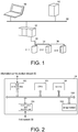
- Fig. 1 is a diagram illustrating a schematic configuration of a device in the control system.
- the control system 1 includes a control device 10, a slave device 211, a slave device 212, a slave device 213, a field network 30, an information communication network 60, the personal computer 61, and a database device 62, as illustrated in Fig. 1 .
- the number of slave devices is not limited thereto, and may be another number.
- the field network 30 is realized by connecting a plurality of slave devices 211, 212, and 213 with communication cables.
- the control device 10 is connected to the slave device 211 via a communication cable
- the slave device 211 is connected to the slave device 212 via a communication cable
- the slave device 212 is connected to the slave device 213 via a communication cable, as illustrated in Fig. 1 .
- the control device 10 is connected to the slave device 212 via the communication cable, the slave device 211, and the communication cable.
- the control device 10 is connected to the slave device 213 via the communication cable, the slave device 211, the communication cable, the slave device 212, and the communication cable.
- the field network 30 is a network conforming to, for example, EtherCAT (registered trademark) as a network standard.
- the field network 30 is not limited thereto, and may be a network in which a controller transmits data in one frame to all slave devices logically connected to a ring network, and the slave device performs "on the fly" on the received frame, thereby realizing time synchronization.
- the information communication network 60 is, for example, a network conforming to Ethernet (registered trademark) as a network standard.
- the control device 10, the personal computer 61, and the database device 62 are connected to one another by an information communication network 60.
- An editing tool for the control program, or the like is installed in the personal computer 61.
- the personal computer 61 creates, edits, and outputs a control program for the control device 10, the slave device 211, the slave device 212, and the slave device 213.
- the personal computer 61 outputs the control program to the control device 10.
- the slave device 211, the slave device 212, and the slave device 213, which are control targets, a control command for each slave device, and the like are described in this control program.
- the personal computer 61 stores an execution program for a running-in operation.
- the personal computer 61 outputs the execution program for a running-in operation to the control device 10 in response to an operation input from the user. Further, the personal computer 61 displays a diagnosis result for the field network 30 according to the execution program for a running-in operation.
- An example of a specific display screen will be described below.
- the database device 62 stores, for example, logs of the respective devices acquired from the control device 10.
- the database device 62 may store the diagnosis result for the field network 30 described above, and a past log of coping methods.
- the control device 10 is specifically realized by, for example, a programmable logic controller (PLC).
- PLC programmable logic controller
- the control device 10 may be another device as long as the device communicates control data and data for a diagnosis of the field network 30 via the field network 30.
- the control device 10 for example, generates control data to be communicated via the field network 30 using the control program from the personal computer 61.
- control device 10 for example, generates the data for a diagnosis of the field network 30 such as the data for actual measurement of propagation delay on the basis of the execution program for a running-in operation from the personal computer 61.
- the slave device 211, the slave device 212, and the slave device 213 are specifically realized by, for example, a servo driver, or a measurement device such as a sensor. These slave devices may be, for example, a robot device or a robot control device connected to the robot device.
- the control device 10, the slave device 211, the slave device 212, and the slave device 213 communicate control data according to a communication cycle preset by the control program or the like, and execute operations and processes in synchronization with a predetermined timing based on the control cycle.
- the control device 10, the slave device 211, the slave device 212, and the slave device 213 perform transmission and reception of the data for actual measurement of propagation delay. Specifically, as outbound processing, the control device 10 transmits the data for actual measurement of propagation delay to the slave device 211.
- the slave device 211 receives the data for actual measurement of propagation delay from the control device 10, writes a time stamp to the data for actual measurement of propagation delay, and transmits the resultant data for actual measurement of propagation delay to the slave device 212 on the end side.
- the slave device 212 receives the data for actual measurement of propagation delay from the slave device 211, writes a time stamp to the data for actual measurement of propagation delay, and transmits the resultant data for actual measurement of propagation delay to the slave device 213 on the end side. Thereafter, as a returning process, when the slave device 213 receives the data for actual measurement of propagation delay from the slave device 212, the slave device 213 writes a time stamp to the data for actual measurement of propagation delay, and returns and transmits the resultant data for actual measurement of propagation delay to the slave device 212.
- the slave device 212 receives the data for actual measurement of propagation delay from the slave device 213, writes a time stamp to the data for actual measurement of propagation delay, and transmits the resultant data for actual measurement of propagation delay to the slave device 211.
- the slave device 211 receives the data for actual measurement of propagation delay from the slave device 212, writes a time stamp to the data for actual measurement of propagation delay, and transmits the resultant data for actual measurement of propagation delay to the control device 10.
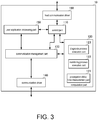
- Fig. 2 is a block diagram illustrating a hardware configuration of the control device.
- the control device 10 includes a CPU 101, a memory 102, a storage medium 103, a transmission and reception part 104, and a host communication part 105, as illustrated in Fig. 2 .
- the CPU 101, the memory 102, the storage medium 103, the transmission and reception part 104, and the host communication part 105 are connected to one another by a data bus 100.
- the CPU 101 reads a system program and a user application program stored in the storage medium 103 into the memory 102 and executes the program, thereby realizing each process of each functional block to be described below.
- the user application program includes, for example, the control program and the execution program for a running-in operation described above.
- the memory 102 is realized by a volatile storage element such as a DRAM or an SRAM. Further, the storage medium 103 is realized by a nonvolatile storage medium such as a magnetic storage medium or a flash memory.
- the transmission and reception part 104 is an interface of the field network 30 in the control device 10.
- the transmission and reception part 104 executes transmission and reception (communication) of control data conforming to a cyclic cycle. Further, the transmission and reception part 104 executes transmission and reception of the data for actual measurement of propagation delay.
- the host communication part 105 is an interface of the information communication network 60 in the control device 10 and executes communication with each device (the personal computer 61, the database device 62, or the like) of a host system described above.
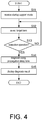
- Fig. 3 is a functional block diagram of the control device.
- the control device 10 includes the control part 110, the computation part 120, the communication management part 130, the communication driver 140, the user application processing part 150, and the host communication driver 160, as illustrated in Fig. 3 .
- the control part 110 performs, for example, scheduling of an overall operation (process) of the control device 10 to execute operation control of the computation part 120, operation control of the user application processing part 150, and operation control of the computation part 12.
- the computation part 120 includes the propagation delay time measurement part 121, the monitoring process execution part 122, and the diagnosis process execution part 123.
- the propagation delay time measurement part 121 generates the data for actual measurement of propagation delay according to the execution program for a running-in operation, and outputs the data for actual measurement of propagation delay to the communication management part 130. Further, the propagation delay time measurement part 121 acquires the received data of the data for actual measurement of propagation delay via the communication management part 130. The propagation delay time measurement part 121 calculates a propagation delay time of each slave device and a propagation delay time due to a plurality of slave device groups from the time stamp written to the received data.
- the monitoring process execution part 122 calculates a bandwidth load status of the field network 30 from the propagation delay time according to the execution program for a running-in operation. Specifically, the monitoring process execution part 122 calculates the bandwidth load status from a ratio of the propagation delay time of all frames transmitted within one cycle to the preset communication cycle.
- the diagnosis process execution part 123 starts up a cable diagnosis mode to execute the cable diagnosis when the received data cannot be acquired within a predetermined time based on the communication cycle despite the fact that the data for actual measurement of propagation delay has been transmitted.
- a known method can be used for cable diagnosis.
- the computation part 120 generates a diagnosis result using processing results of the propagation delay time measurement part 121, the monitoring process execution part 122, and the diagnosis process execution part 123.
- the computation part 120 outputs the diagnosis result to the control part 110, and the control part 110 outputs the diagnosis result to the personal computer 61 connected to the information communication network 60 via the host communication driver 160.
- the communication management part 130 executes scheduling of communication of the control data. Further, the communication management part 130 executes management of transmission and reception of the data for actual measurement of propagation delay.
- the communication driver 140 executes control of the transmission and reception part 104 to communicate the control data via the field network 30 according to the cyclic cycle. Further, the communication driver 140 communicates the data for actual measurement of propagation delay via the field network 30.
- the user application processing part 150 executes the user application program including the control program and the execution program of a running-in operation described above.
- control device 10 executes the running-in operation to generate a diagnosis result for the field network 30 before a main operation.
- the control device 10 outputs the diagnosis result to the personal computer 61, and the personal computer 61 displays the diagnosis result.
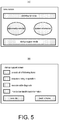
- Fig. 4 is a flowchart of the control method.
- the personal computer 61 receives an operation input in a startup support mode (S11).
- the personal computer 61 executes selection of a diagnosis target item (S12).
- the personal computer 61 receives the execution operation (S13: YES)
- the personal computer 61 instructs the control device 10 to execute the diagnosis of the field network 30.
- the control device 10 measures the propagation delay time and executes diagnosis using the propagation delay time (S14).
- the control device 10 outputs a diagnosis result to the personal computer 61, and the personal computer 61 displays the diagnosis result (S15).
- FIGs. 5(A) and 5(B) are diagrams illustrating an example of a display screen in the diagnostic mode.
- a Home screen for startup support as illustrated in (A) of FIG. 5 is displayed on a screen of the personal computer 61.
- An icon for receiving an operation input for a display of an abnormality status, an icon for receiving an operation input for abnormality release, an icon for receiving selection of a display of system information, and an icon for receiving execution of the startup support mode are displayed on the Home screen, as illustrated in (A) of Fig. 5 .
- the startup support mode in which an operation status of the field network 30 is detected is executed.
- a screen illustrated in (B) of Fig. 5 is displayed.
- a plurality of items to be executed, a box for selecting whether or not the plurality of items is executed, an icon for receiving an operation input for execution, and an icon for receiving an operation input for returning to the Home screen are displayed on the startup support screen, as illustrated in (B) of Fig. 5 .
- the plurality of items includes items such as "execute all items”, “execute a running-in operation”, “execute cable diagnosis”, and “monitor bandwidth load information”.
- items such as "execute all items”, “execute a running-in operation”, “execute cable diagnosis”, and “monitor bandwidth load information”.
- control device 10 executes the running-in operation using the field network 30. In this case, transmission and reception of the data for actual measurement of propagation delay are performed.
- the control device 10 executes the cable diagnosis for the field network 30. Specifically, when the data for actual measurement of propagation delay is not returned within the predetermined time based on the communication cycle, the control device 10 determines that cable diagnosis is necessary, and executes the cable diagnosis mode. When the data for actual measurement of propagation delay is returned within the predetermined time based on the communication cycle, the control device 10 outputs a diagnosis result indicating that there is no problem in the cables.
- the control device 10 transmits or receives the data for actual measurement of propagation delay and acquires the time stamp.
- the control device 10 calculates the propagation delay time from the time stamp, and calculates the bandwidth load from a ratio of the propagation delay time to the preset communication cycle.
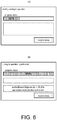
- FIGs. 6(A) and 6(B) are diagrams illustrating an example of a display screen of a diagnosis result.
- a progress status of the running-in operation that is, a progress status of the diagnosis based on the selected item is displayed, as illustrated in (A) of Fig. 6 . Further, in the running-in operation, a currently executed process and a currently known diagnosis result are displayed in an area under the progress status.
- a progress status of the running-in operation (100% completed) is displayed, as illustrated in (B) of Fig. 6 . Further, a diagnosis result is displayed in an area under the progress status after ending of the running-in operation.
- Such a display enables the user to recognize how the field network 30 operates, before a main operation starts, by setting the control program. Thereby, normal startup of the control system can be realized more reliably.
Landscapes
- Engineering & Computer Science (AREA)
- Signal Processing (AREA)
- Computer Networks & Wireless Communication (AREA)
- General Physics & Mathematics (AREA)
- Environmental & Geological Engineering (AREA)
- Physics & Mathematics (AREA)
- Automation & Control Theory (AREA)
- General Engineering & Computer Science (AREA)
- Manufacturing & Machinery (AREA)
- Quality & Reliability (AREA)
- Computer Security & Cryptography (AREA)
- Testing And Monitoring For Control Systems (AREA)
- Programmable Controllers (AREA)
Applications Claiming Priority (2)
| Application Number | Priority Date | Filing Date | Title |
|---|---|---|---|
| JP2018045124A JP6969454B2 (ja) | 2018-03-13 | 2018-03-13 | 制御装置、制御方法、および、制御プログラム |
| PCT/JP2019/001744 WO2019176286A1 (fr) | 2018-03-13 | 2019-01-22 | Dispositif, procédé et programme de commande |
Publications (3)
| Publication Number | Publication Date |
|---|---|
| EP3767407A1 true EP3767407A1 (fr) | 2021-01-20 |
| EP3767407A4 EP3767407A4 (fr) | 2021-11-10 |
| EP3767407B1 EP3767407B1 (fr) | 2023-07-19 |
Family
ID=67908315
Family Applications (1)
| Application Number | Title | Priority Date | Filing Date |
|---|---|---|---|
| EP19766943.5A Active EP3767407B1 (fr) | 2018-03-13 | 2019-01-22 | Diagnostic de système de bus de terrain à l'aide de mesures de temps de propagation |
Country Status (5)
| Country | Link |
|---|---|
| US (1) | US11092945B2 (fr) |
| EP (1) | EP3767407B1 (fr) |
| JP (1) | JP6969454B2 (fr) |
| CN (1) | CN111033400B (fr) |
| WO (1) | WO2019176286A1 (fr) |
Families Citing this family (1)
| Publication number | Priority date | Publication date | Assignee | Title |
|---|---|---|---|---|
| JP6969455B2 (ja) * | 2018-03-13 | 2021-11-24 | オムロン株式会社 | 制御装置、制御システム、制御方法、および、制御プログラム |
Family Cites Families (15)
| Publication number | Priority date | Publication date | Assignee | Title |
|---|---|---|---|---|
| JPH10133966A (ja) * | 1996-10-30 | 1998-05-22 | Hitachi Ltd | プロセス入出力装置 |
| DE19831405A1 (de) * | 1998-07-13 | 2000-01-20 | Siemens Ag | Steuerungssystem mit einem Personalcomputer |
| US7370110B2 (en) * | 2000-04-18 | 2008-05-06 | Hoshiko Llc | Method and system for operating a network server to discourage inappropriate use |
| ES2265055T3 (es) * | 2001-10-17 | 2007-02-01 | Siemens Aktiengesellschaft | Proceso para el funcionamiento de un usuario final de un sistema de comunicacion isocrono y ciclico. |
| US7631229B2 (en) * | 2006-04-24 | 2009-12-08 | Freescale Semiconductor, Inc. | Selective bit error detection at a bus device |
| US8072999B1 (en) * | 2007-05-08 | 2011-12-06 | Motion Engineering Inc. | Method and system for removing and returning nodes in a synchronous network |
| EP2034668B1 (fr) * | 2007-09-05 | 2010-12-29 | Siemens Aktiengesellschaft | Système de communication hautement disponible |
| US9065668B1 (en) * | 2010-02-02 | 2015-06-23 | Qualcomm Incorporated | Distributed bandwidth control in a communication network |
| JP5184597B2 (ja) * | 2010-09-06 | 2013-04-17 | 株式会社日立産機システム | 通信制御装置及び通信・制御システム |
| CN101950175B (zh) * | 2010-10-21 | 2012-07-04 | 广州数控设备有限公司 | 一种基于工业以太网的高速现场总线实现方法 |
| DE102012101957B3 (de) * | 2012-03-08 | 2013-05-29 | Softing Ag | Busteilnehmer-Einrichtung zum Anschluss an einen linienredundanten, seriellen Datenbus und Verfahren zur Steuerung der Kommunikation eines Busteilnehmers mit einem linienredundanten, seriellen Datenbus |
| JP6358088B2 (ja) * | 2012-03-15 | 2018-07-18 | オムロン株式会社 | 制御装置、情報処理装置、制御方法、コンピュータ読取可能な記録媒体、およびプログラム |
| JP6299064B2 (ja) | 2013-01-25 | 2018-03-28 | オムロン株式会社 | 制御装置、制御方法、およびプログラム |
| JP6284043B2 (ja) * | 2015-12-25 | 2018-02-28 | 横河電機株式会社 | プロセス制御システム |
| JP6399136B1 (ja) * | 2017-03-31 | 2018-10-03 | オムロン株式会社 | 制御装置、制御プログラム、および制御システム |
-
2018
- 2018-03-13 JP JP2018045124A patent/JP6969454B2/ja active Active
-
2019
- 2019-01-22 EP EP19766943.5A patent/EP3767407B1/fr active Active
- 2019-01-22 CN CN201980003959.1A patent/CN111033400B/zh active Active
- 2019-01-22 US US16/640,057 patent/US11092945B2/en active Active
- 2019-01-22 WO PCT/JP2019/001744 patent/WO2019176286A1/fr unknown
Also Published As
| Publication number | Publication date |
|---|---|
| EP3767407B1 (fr) | 2023-07-19 |
| EP3767407A4 (fr) | 2021-11-10 |
| US20200225645A1 (en) | 2020-07-16 |
| JP6969454B2 (ja) | 2021-11-24 |
| CN111033400A (zh) | 2020-04-17 |
| US11092945B2 (en) | 2021-08-17 |
| CN111033400B (zh) | 2023-02-21 |
| WO2019176286A1 (fr) | 2019-09-19 |
| JP2019159753A (ja) | 2019-09-19 |
Similar Documents
| Publication | Publication Date | Title |
|---|---|---|
| EP3382481B1 (fr) | Organe de commande, programme de commande et domaine de système de commande | |
| US8249726B2 (en) | Method and device for accessing a functional module of automation system | |
| US10591886B2 (en) | Control system, control program, and control method for device switching responsive to abnormality detection | |
| EP3379358B1 (fr) | Système, dispositif, programme et procédé de commande | |
| EP3432463B1 (fr) | Système de commande de moteur, dispositif de commande de moteur, programme et support d'enregistrement | |
| JP2018151918A (ja) | 制御装置、データ構造、情報処理方法 | |
| JP2017079009A (ja) | プログラマブル・ロジック・コントローラのモニタ装置 | |
| EP3376316B1 (fr) | Dispositif esclave, procédé de commande d'un dispositif esclave, programme de traitement d'informations et support d'enregistrement lisible par ordinateur | |
| JP6998781B2 (ja) | 故障診断システム | |
| EP3767407A1 (fr) | Dispositif, procédé et programme de commande | |
| CN112673326A (zh) | 控制装置及控制程序 | |
| US20210181709A1 (en) | Data collection system and motor controller | |
| EP3767413B1 (fr) | Dispositif de commande, système de commande, procédé de commande, et programme de commande | |
| EP3564766A1 (fr) | Appareil de support, programme de support et procédé de réglage | |
| EP3764175B1 (fr) | Dispositif de commande et système de commande | |
| US20220376806A1 (en) | Control system, communication control method of control system, and control device | |
| EP3767409A1 (fr) | Système d'automatisation industrielle (fa), dispositif de commande, et procédé de commande | |
| US9336181B2 (en) | Retrieval of measured values, diagnostic information or device parameters | |
| CN104570826A (zh) | 用于再现自动化设备的程序进程的方法 | |
| US11226603B2 (en) | Automation system for process automation and a corresponding method | |
| EP3845986A1 (fr) | Système de collecte de données de dispositif industriel et dispositif de commande de moteur | |
| EP3396538A1 (fr) | Procédé et appareil pour le déploiement d'un agent à un dispositif cible d'un système cible | |
| JP2012059128A (ja) | 制御装置用プログラミングツール及び制御装置用プログラムの作成支援方法 | |
| KR20160141965A (ko) | 프로피버스 통신 시스템 |
Legal Events
| Date | Code | Title | Description |
|---|---|---|---|
| STAA | Information on the status of an ep patent application or granted ep patent |
Free format text: STATUS: THE INTERNATIONAL PUBLICATION HAS BEEN MADE |
|
| PUAI | Public reference made under article 153(3) epc to a published international application that has entered the european phase |
Free format text: ORIGINAL CODE: 0009012 |
|
| STAA | Information on the status of an ep patent application or granted ep patent |
Free format text: STATUS: REQUEST FOR EXAMINATION WAS MADE |
|
| 17P | Request for examination filed |
Effective date: 20200214 |
|
| AK | Designated contracting states |
Kind code of ref document: A1 Designated state(s): AL AT BE BG CH CY CZ DE DK EE ES FI FR GB GR HR HU IE IS IT LI LT LU LV MC MK MT NL NO PL PT RO RS SE SI SK SM TR |
|
| AX | Request for extension of the european patent |
Extension state: BA ME |
|
| DAV | Request for validation of the european patent (deleted) | ||
| DAX | Request for extension of the european patent (deleted) | ||
| A4 | Supplementary search report drawn up and despatched |
Effective date: 20211013 |
|
| RIC1 | Information provided on ipc code assigned before grant |
Ipc: H04L 12/26 20060101ALI20211007BHEP Ipc: G05B 19/418 20060101ALI20211007BHEP Ipc: G05B 19/042 20060101ALI20211007BHEP Ipc: H04L 12/40 20060101AFI20211007BHEP |
|
| REG | Reference to a national code |
Ref country code: DE Ref legal event code: R079 Ref document number: 602019033106 Country of ref document: DE Free format text: PREVIOUS MAIN CLASS: G05B0019050000 Ipc: H04L0012400000 Ref country code: DE Ref legal event code: R079 Free format text: PREVIOUS MAIN CLASS: G05B0019050000 Ipc: H04L0012400000 |
|
| GRAP | Despatch of communication of intention to grant a patent |
Free format text: ORIGINAL CODE: EPIDOSNIGR1 |
|
| STAA | Information on the status of an ep patent application or granted ep patent |
Free format text: STATUS: GRANT OF PATENT IS INTENDED |
|
| RIC1 | Information provided on ipc code assigned before grant |
Ipc: H04L 43/0852 20220101ALI20230201BHEP Ipc: H04L 43/0817 20220101ALI20230201BHEP Ipc: G05B 19/418 20060101ALI20230201BHEP Ipc: G05B 19/042 20060101ALI20230201BHEP Ipc: H04L 12/40 20060101AFI20230201BHEP |
|
| INTG | Intention to grant announced |
Effective date: 20230227 |
|
| GRAS | Grant fee paid |
Free format text: ORIGINAL CODE: EPIDOSNIGR3 |
|
| GRAA | (expected) grant |
Free format text: ORIGINAL CODE: 0009210 |
|
| STAA | Information on the status of an ep patent application or granted ep patent |
Free format text: STATUS: THE PATENT HAS BEEN GRANTED |
|
| AK | Designated contracting states |
Kind code of ref document: B1 Designated state(s): AL AT BE BG CH CY CZ DE DK EE ES FI FR GB GR HR HU IE IS IT LI LT LU LV MC MK MT NL NO PL PT RO RS SE SI SK SM TR |
|
| REG | Reference to a national code |
Ref country code: GB Ref legal event code: FG4D |
|
| REG | Reference to a national code |
Ref country code: CH Ref legal event code: EP |
|
| REG | Reference to a national code |
Ref country code: DE Ref legal event code: R096 Ref document number: 602019033106 Country of ref document: DE |
|
| REG | Reference to a national code |
Ref country code: IE Ref legal event code: FG4D |
|
| REG | Reference to a national code |
Ref country code: LT Ref legal event code: MG9D |
|
| REG | Reference to a national code |
Ref country code: NL Ref legal event code: MP Effective date: 20230719 |
|
| REG | Reference to a national code |
Ref country code: AT Ref legal event code: MK05 Ref document number: 1590584 Country of ref document: AT Kind code of ref document: T Effective date: 20230719 |
|
| PG25 | Lapsed in a contracting state [announced via postgrant information from national office to epo] |
Ref country code: NL Free format text: LAPSE BECAUSE OF FAILURE TO SUBMIT A TRANSLATION OF THE DESCRIPTION OR TO PAY THE FEE WITHIN THE PRESCRIBED TIME-LIMIT Effective date: 20230719 |
|
| PG25 | Lapsed in a contracting state [announced via postgrant information from national office to epo] |
Ref country code: GR Free format text: LAPSE BECAUSE OF FAILURE TO SUBMIT A TRANSLATION OF THE DESCRIPTION OR TO PAY THE FEE WITHIN THE PRESCRIBED TIME-LIMIT Effective date: 20231020 |
|
| PG25 | Lapsed in a contracting state [announced via postgrant information from national office to epo] |
Ref country code: IS Free format text: LAPSE BECAUSE OF FAILURE TO SUBMIT A TRANSLATION OF THE DESCRIPTION OR TO PAY THE FEE WITHIN THE PRESCRIBED TIME-LIMIT Effective date: 20231119 |
|
| PG25 | Lapsed in a contracting state [announced via postgrant information from national office to epo] |
Ref country code: SE Free format text: LAPSE BECAUSE OF FAILURE TO SUBMIT A TRANSLATION OF THE DESCRIPTION OR TO PAY THE FEE WITHIN THE PRESCRIBED TIME-LIMIT Effective date: 20230719 Ref country code: RS Free format text: LAPSE BECAUSE OF FAILURE TO SUBMIT A TRANSLATION OF THE DESCRIPTION OR TO PAY THE FEE WITHIN THE PRESCRIBED TIME-LIMIT Effective date: 20230719 Ref country code: PT Free format text: LAPSE BECAUSE OF FAILURE TO SUBMIT A TRANSLATION OF THE DESCRIPTION OR TO PAY THE FEE WITHIN THE PRESCRIBED TIME-LIMIT Effective date: 20231120 Ref country code: NO Free format text: LAPSE BECAUSE OF FAILURE TO SUBMIT A TRANSLATION OF THE DESCRIPTION OR TO PAY THE FEE WITHIN THE PRESCRIBED TIME-LIMIT Effective date: 20231019 Ref country code: LV Free format text: LAPSE BECAUSE OF FAILURE TO SUBMIT A TRANSLATION OF THE DESCRIPTION OR TO PAY THE FEE WITHIN THE PRESCRIBED TIME-LIMIT Effective date: 20230719 Ref country code: LT Free format text: LAPSE BECAUSE OF FAILURE TO SUBMIT A TRANSLATION OF THE DESCRIPTION OR TO PAY THE FEE WITHIN THE PRESCRIBED TIME-LIMIT Effective date: 20230719 Ref country code: IS Free format text: LAPSE BECAUSE OF FAILURE TO SUBMIT A TRANSLATION OF THE DESCRIPTION OR TO PAY THE FEE WITHIN THE PRESCRIBED TIME-LIMIT Effective date: 20231119 Ref country code: HR Free format text: LAPSE BECAUSE OF FAILURE TO SUBMIT A TRANSLATION OF THE DESCRIPTION OR TO PAY THE FEE WITHIN THE PRESCRIBED TIME-LIMIT Effective date: 20230719 Ref country code: GR Free format text: LAPSE BECAUSE OF FAILURE TO SUBMIT A TRANSLATION OF THE DESCRIPTION OR TO PAY THE FEE WITHIN THE PRESCRIBED TIME-LIMIT Effective date: 20231020 Ref country code: FI Free format text: LAPSE BECAUSE OF FAILURE TO SUBMIT A TRANSLATION OF THE DESCRIPTION OR TO PAY THE FEE WITHIN THE PRESCRIBED TIME-LIMIT Effective date: 20230719 Ref country code: AT Free format text: LAPSE BECAUSE OF FAILURE TO SUBMIT A TRANSLATION OF THE DESCRIPTION OR TO PAY THE FEE WITHIN THE PRESCRIBED TIME-LIMIT Effective date: 20230719 |
|
| PG25 | Lapsed in a contracting state [announced via postgrant information from national office to epo] |
Ref country code: PL Free format text: LAPSE BECAUSE OF FAILURE TO SUBMIT A TRANSLATION OF THE DESCRIPTION OR TO PAY THE FEE WITHIN THE PRESCRIBED TIME-LIMIT Effective date: 20230719 |
|
| PG25 | Lapsed in a contracting state [announced via postgrant information from national office to epo] |
Ref country code: ES Free format text: LAPSE BECAUSE OF FAILURE TO SUBMIT A TRANSLATION OF THE DESCRIPTION OR TO PAY THE FEE WITHIN THE PRESCRIBED TIME-LIMIT Effective date: 20230719 |
|
| PG25 | Lapsed in a contracting state [announced via postgrant information from national office to epo] |
Ref country code: SM Free format text: LAPSE BECAUSE OF FAILURE TO SUBMIT A TRANSLATION OF THE DESCRIPTION OR TO PAY THE FEE WITHIN THE PRESCRIBED TIME-LIMIT Effective date: 20230719 Ref country code: RO Free format text: LAPSE BECAUSE OF FAILURE TO SUBMIT A TRANSLATION OF THE DESCRIPTION OR TO PAY THE FEE WITHIN THE PRESCRIBED TIME-LIMIT Effective date: 20230719 Ref country code: ES Free format text: LAPSE BECAUSE OF FAILURE TO SUBMIT A TRANSLATION OF THE DESCRIPTION OR TO PAY THE FEE WITHIN THE PRESCRIBED TIME-LIMIT Effective date: 20230719 Ref country code: EE Free format text: LAPSE BECAUSE OF FAILURE TO SUBMIT A TRANSLATION OF THE DESCRIPTION OR TO PAY THE FEE WITHIN THE PRESCRIBED TIME-LIMIT Effective date: 20230719 Ref country code: DK Free format text: LAPSE BECAUSE OF FAILURE TO SUBMIT A TRANSLATION OF THE DESCRIPTION OR TO PAY THE FEE WITHIN THE PRESCRIBED TIME-LIMIT Effective date: 20230719 Ref country code: CZ Free format text: LAPSE BECAUSE OF FAILURE TO SUBMIT A TRANSLATION OF THE DESCRIPTION OR TO PAY THE FEE WITHIN THE PRESCRIBED TIME-LIMIT Effective date: 20230719 Ref country code: SK Free format text: LAPSE BECAUSE OF FAILURE TO SUBMIT A TRANSLATION OF THE DESCRIPTION OR TO PAY THE FEE WITHIN THE PRESCRIBED TIME-LIMIT Effective date: 20230719 |
|
| PGFP | Annual fee paid to national office [announced via postgrant information from national office to epo] |
Ref country code: DE Payment date: 20240119 Year of fee payment: 6 |