EP3767299A1 - Automatic analyzing apparatus, and method for detecting flow path clogging of the automatic analyzing apparatus - Google Patents
Automatic analyzing apparatus, and method for detecting flow path clogging of the automatic analyzing apparatus Download PDFInfo
- Publication number
- EP3767299A1 EP3767299A1 EP19767024.3A EP19767024A EP3767299A1 EP 3767299 A1 EP3767299 A1 EP 3767299A1 EP 19767024 A EP19767024 A EP 19767024A EP 3767299 A1 EP3767299 A1 EP 3767299A1
- Authority
- EP
- European Patent Office
- Prior art keywords
- vacuum
- vacuum tank
- solenoid valve
- flow path
- clogging
- Prior art date
- Legal status (The legal status is an assumption and is not a legal conclusion. Google has not performed a legal analysis and makes no representation as to the accuracy of the status listed.)
- Granted
Links
Images



Classifications
-
- G—PHYSICS
- G01—MEASURING; TESTING
- G01N—INVESTIGATING OR ANALYSING MATERIALS BY DETERMINING THEIR CHEMICAL OR PHYSICAL PROPERTIES
- G01N35/00—Automatic analysis not limited to methods or materials provided for in any single one of groups G01N1/00 - G01N33/00; Handling materials therefor
- G01N35/10—Devices for transferring samples or any liquids to, in, or from, the analysis apparatus, e.g. suction devices, injection devices
- G01N35/1095—Devices for transferring samples or any liquids to, in, or from, the analysis apparatus, e.g. suction devices, injection devices for supplying the samples to flow-through analysers
-
- G—PHYSICS
- G01—MEASURING; TESTING
- G01M—TESTING STATIC OR DYNAMIC BALANCE OF MACHINES OR STRUCTURES; TESTING OF STRUCTURES OR APPARATUS, NOT OTHERWISE PROVIDED FOR
- G01M3/00—Investigating fluid-tightness of structures
- G01M3/02—Investigating fluid-tightness of structures by using fluid or vacuum
- G01M3/26—Investigating fluid-tightness of structures by using fluid or vacuum by measuring rate of loss or gain of fluid, e.g. by pressure-responsive devices, by flow detectors
-
- G—PHYSICS
- G01—MEASURING; TESTING
- G01N—INVESTIGATING OR ANALYSING MATERIALS BY DETERMINING THEIR CHEMICAL OR PHYSICAL PROPERTIES
- G01N35/00—Automatic analysis not limited to methods or materials provided for in any single one of groups G01N1/00 - G01N33/00; Handling materials therefor
- G01N35/10—Devices for transferring samples or any liquids to, in, or from, the analysis apparatus, e.g. suction devices, injection devices
- G01N35/1004—Cleaning sample transfer devices
-
- G—PHYSICS
- G01—MEASURING; TESTING
- G01N—INVESTIGATING OR ANALYSING MATERIALS BY DETERMINING THEIR CHEMICAL OR PHYSICAL PROPERTIES
- G01N35/00—Automatic analysis not limited to methods or materials provided for in any single one of groups G01N1/00 - G01N33/00; Handling materials therefor
- G01N35/10—Devices for transferring samples or any liquids to, in, or from, the analysis apparatus, e.g. suction devices, injection devices
- G01N35/1009—Characterised by arrangements for controlling the aspiration or dispense of liquids
- G01N35/1016—Control of the volume dispensed or introduced
-
- G—PHYSICS
- G08—SIGNALLING
- G08B—SIGNALLING SYSTEMS, e.g. PERSONAL CALLING SYSTEMS; ORDER TELEGRAPHS; ALARM SYSTEMS
- G08B5/00—Visible signalling systems, e.g. visible personal calling systems or remote indication of seats occupied
- G08B5/22—Visible signalling systems, e.g. visible personal calling systems or remote indication of seats occupied using electric transmission; using electromagnetic transmission
- G08B5/36—Visible signalling systems, e.g. visible personal calling systems or remote indication of seats occupied using electric transmission; using electromagnetic transmission using visible light sources
-
- A—HUMAN NECESSITIES
- A61—MEDICAL OR VETERINARY SCIENCE; HYGIENE
- A61B—DIAGNOSIS; SURGERY; IDENTIFICATION
- A61B1/00—Instruments for performing medical examinations of the interior of cavities or tubes of the body by visual or photographical inspection, e.g. endoscopes; Illuminating arrangements therefor
-
- B—PERFORMING OPERATIONS; TRANSPORTING
- B23—MACHINE TOOLS; METAL-WORKING NOT OTHERWISE PROVIDED FOR
- B23Q—DETAILS, COMPONENTS, OR ACCESSORIES FOR MACHINE TOOLS, e.g. ARRANGEMENTS FOR COPYING OR CONTROLLING; MACHINE TOOLS IN GENERAL CHARACTERISED BY THE CONSTRUCTION OF PARTICULAR DETAILS OR COMPONENTS; COMBINATIONS OR ASSOCIATIONS OF METAL-WORKING MACHINES, NOT DIRECTED TO A PARTICULAR RESULT
- B23Q11/00—Accessories fitted to machine tools for keeping tools or parts of the machine in good working condition or for cooling work; Safety devices specially combined with or arranged in, or specially adapted for use in connection with, machine tools
- B23Q11/10—Arrangements for cooling or lubricating tools or work
-
- B—PERFORMING OPERATIONS; TRANSPORTING
- B23—MACHINE TOOLS; METAL-WORKING NOT OTHERWISE PROVIDED FOR
- B23Q—DETAILS, COMPONENTS, OR ACCESSORIES FOR MACHINE TOOLS, e.g. ARRANGEMENTS FOR COPYING OR CONTROLLING; MACHINE TOOLS IN GENERAL CHARACTERISED BY THE CONSTRUCTION OF PARTICULAR DETAILS OR COMPONENTS; COMBINATIONS OR ASSOCIATIONS OF METAL-WORKING MACHINES, NOT DIRECTED TO A PARTICULAR RESULT
- B23Q17/00—Arrangements for observing, indicating or measuring on machine tools
- B23Q17/09—Arrangements for observing, indicating or measuring on machine tools for indicating or measuring cutting pressure or for determining cutting-tool condition, e.g. cutting ability, load on tool
-
- G—PHYSICS
- G01—MEASURING; TESTING
- G01F—MEASURING VOLUME, VOLUME FLOW, MASS FLOW OR LIQUID LEVEL; METERING BY VOLUME
- G01F1/00—Measuring the volume flow or mass flow of fluid or fluent solid material wherein the fluid passes through a meter in a continuous flow
- G01F1/74—Devices for measuring flow of a fluid or flow of a fluent solid material in suspension in another fluid
-
- G—PHYSICS
- G01—MEASURING; TESTING
- G01M—TESTING STATIC OR DYNAMIC BALANCE OF MACHINES OR STRUCTURES; TESTING OF STRUCTURES OR APPARATUS, NOT OTHERWISE PROVIDED FOR
- G01M1/00—Testing static or dynamic balance of machines or structures
- G01M1/30—Compensating imbalance
- G01M1/36—Compensating imbalance by adjusting position of masses built-in the body to be tested
-
- G—PHYSICS
- G01—MEASURING; TESTING
- G01N—INVESTIGATING OR ANALYSING MATERIALS BY DETERMINING THEIR CHEMICAL OR PHYSICAL PROPERTIES
- G01N35/00—Automatic analysis not limited to methods or materials provided for in any single one of groups G01N1/00 - G01N33/00; Handling materials therefor
- G01N35/00584—Control arrangements for automatic analysers
- G01N35/00594—Quality control, including calibration or testing of components of the analyser
- G01N35/00613—Quality control
- G01N35/00623—Quality control of instruments
- G01N2035/00633—Quality control of instruments logging process history of individual samples
-
- G—PHYSICS
- G01—MEASURING; TESTING
- G01N—INVESTIGATING OR ANALYSING MATERIALS BY DETERMINING THEIR CHEMICAL OR PHYSICAL PROPERTIES
- G01N35/00—Automatic analysis not limited to methods or materials provided for in any single one of groups G01N1/00 - G01N33/00; Handling materials therefor
- G01N35/10—Devices for transferring samples or any liquids to, in, or from, the analysis apparatus, e.g. suction devices, injection devices
- G01N35/1009—Characterised by arrangements for controlling the aspiration or dispense of liquids
- G01N35/1016—Control of the volume dispensed or introduced
- G01N2035/1018—Detecting inhomogeneities, e.g. foam, bubbles, clots
-
- G—PHYSICS
- G01—MEASURING; TESTING
- G01N—INVESTIGATING OR ANALYSING MATERIALS BY DETERMINING THEIR CHEMICAL OR PHYSICAL PROPERTIES
- G01N33/00—Investigating or analysing materials by specific methods not covered by groups G01N1/00 - G01N31/00
- G01N33/48—Biological material, e.g. blood, urine; Haemocytometers
- G01N33/50—Chemical analysis of biological material, e.g. blood, urine; Testing involving biospecific ligand binding methods; Immunological testing
- G01N33/53—Immunoassay; Biospecific binding assay; Materials therefor
- G01N33/543—Immunoassay; Biospecific binding assay; Materials therefor with an insoluble carrier for immobilising immunochemicals
-
- G—PHYSICS
- G01—MEASURING; TESTING
- G01N—INVESTIGATING OR ANALYSING MATERIALS BY DETERMINING THEIR CHEMICAL OR PHYSICAL PROPERTIES
- G01N35/00—Automatic analysis not limited to methods or materials provided for in any single one of groups G01N1/00 - G01N33/00; Handling materials therefor
-
- G—PHYSICS
- G01—MEASURING; TESTING
- G01N—INVESTIGATING OR ANALYSING MATERIALS BY DETERMINING THEIR CHEMICAL OR PHYSICAL PROPERTIES
- G01N35/00—Automatic analysis not limited to methods or materials provided for in any single one of groups G01N1/00 - G01N33/00; Handling materials therefor
- G01N35/00584—Control arrangements for automatic analysers
- G01N35/00594—Quality control, including calibration or testing of components of the analyser
- G01N35/00613—Quality control
- G01N35/00623—Quality control of instruments
-
- G—PHYSICS
- G01—MEASURING; TESTING
- G01N—INVESTIGATING OR ANALYSING MATERIALS BY DETERMINING THEIR CHEMICAL OR PHYSICAL PROPERTIES
- G01N35/00—Automatic analysis not limited to methods or materials provided for in any single one of groups G01N1/00 - G01N33/00; Handling materials therefor
- G01N35/00584—Control arrangements for automatic analysers
- G01N35/00722—Communications; Identification
- G01N35/00871—Communications between instruments or with remote terminals
-
- G—PHYSICS
- G01—MEASURING; TESTING
- G01N—INVESTIGATING OR ANALYSING MATERIALS BY DETERMINING THEIR CHEMICAL OR PHYSICAL PROPERTIES
- G01N35/00—Automatic analysis not limited to methods or materials provided for in any single one of groups G01N1/00 - G01N33/00; Handling materials therefor
- G01N35/02—Automatic analysis not limited to methods or materials provided for in any single one of groups G01N1/00 - G01N33/00; Handling materials therefor using a plurality of sample containers moved by a conveyor system past one or more treatment or analysis stations
-
- G—PHYSICS
- G01—MEASURING; TESTING
- G01N—INVESTIGATING OR ANALYSING MATERIALS BY DETERMINING THEIR CHEMICAL OR PHYSICAL PROPERTIES
- G01N35/00—Automatic analysis not limited to methods or materials provided for in any single one of groups G01N1/00 - G01N33/00; Handling materials therefor
- G01N35/10—Devices for transferring samples or any liquids to, in, or from, the analysis apparatus, e.g. suction devices, injection devices
- G01N35/1002—Reagent dispensers
-
- G—PHYSICS
- G08—SIGNALLING
- G08B—SIGNALLING SYSTEMS, e.g. PERSONAL CALLING SYSTEMS; ORDER TELEGRAPHS; ALARM SYSTEMS
- G08B21/00—Alarms responsive to a single specified undesired or abnormal condition and not otherwise provided for
- G08B21/18—Status alarms
Definitions
- the present invention relates to an automatic analyzer, and a method for detecting flow path clogging of the automatic analyzer.
- An automatic analyzer discharges a certain amount of sample and a certain amount of reagent into a reaction vessel, mixes the sample and the reagent to cause reaction, and analyzes a component, a concentration, and the like of the sample by optically measuring reaction liquid.
- reaction waste liquid in which the sample and the reagent are reacted is generated in the reaction vessel, the waste liquid is suctioned using a vacuum pump or the like in order to remove the reaction waste liquid from the reaction vessel.
- a vacuum pump or the like in order to remove the reaction waste liquid from the reaction vessel.
- Patent Literature 1 WO 07/132632
- the automatic analyzer having a plurality of mechanisms including a mechanism for suctioning the reaction waste liquid and a mechanism for suctioning the cleaning liquid and the like adhered to the surface after probe cleaning, reduces pressure in a vacuum tank by a pressure-reducing pump or the like, arranges a solenoid valve in a flow path from the vacuum tank, opens and closes the solenoid valve, and suctions the waste liquid by a pressure difference in the vacuum tank.
- a contact point of a vacuum switch provided in the vacuum tank is switched and then the analyzer becomes ready for analysis.
- An object of the invention is to provide an automatic analyzer capable of detecting clogging in a flow path and a method for detecting flow path clogging of the automatic analyzer.
- an automatic analyzer of the invention includes a vacuum tank and a vacuum pump that vacuum suctions liquid; a first solenoid valve provided in a flow path connected to the vacuum tank; a determination unit that determines whether a vacuum value in the vacuum tank is equal to or greater than a predetermined threshold, or whether the vacuum value is smaller than the predetermined threshold; and a clogging detection unit that detects clogging in the flow path.
- the clogging detection unit changes the vacuum pump from ON to OFF with the first solenoid valve being in a closed state, and thereafter, changes the first solenoid valve from the closed state to an open state, and detects presence and absence of clogging in the flow path by comparing time that elapses before the determination unit determines that the vacuum value in the vacuum tank is equal to or greater than the predetermined threshold from a time point when the first solenoid valve is changed from the closed state to the open state, to a predetermined threshold.
- a vacuum pump is operated until negative pressure of the vacuum tank becomes constant, and then the vacuum pump is stopped.
- a negative pressure value in the vacuum tank is held at a constant negative pressure value unless there is a normal leak. If the vacuum switch is turned OFF at a certain time, a leak occurs somewhere in the flow path.
- the vacuum pump is stopped when the negative pressure of the vacuum tank is constant, the solenoid valve in the flow path at a part desired to be confirmed and connected to the vacuum tank is opened, and time that elapses before the vacuum switch is turned OFF is measured, and presence and absence of an anomaly in the flow path system is determined by comparing the measured time with a threshold.
- the anomaly of the flow path when there is an anomaly in the flow path, the anomaly of the flow path can be detected without using a sensor for measuring the pressure.
- an automatic analyzer of the invention with a solenoid valve arranged between a vacuum tank and a mechanism requiring vacuum being in a closed state, a vacuum pump is operated until negative pressure of the vacuum tank becomes constant, and then the vacuum pump is stopped. A negative pressure value in the vacuum tank is held at a constant negative pressure value unless there is a normal leak. If a vacuum switch is turned OFF at a certain time, a leak occurs somewhere in the flow path.
- the vacuum pump is stopped when the negative pressure of the vacuum tank is constant, the solenoid valve in the flow path at a part desired to be confirmed and connected to the vacuum tank is opened, and time that elapses before the vacuum switch is turned OFF is measured, and presence and absence of an anomaly in the flow path system is determined by comparing the measured time with a threshold.
- FIG. 1 is a diagram schematically showing the overall configuration of the automatic analyzer according to the present embodiment.
- an automatic analyzer 100 is an apparatus that dispenses a sample and a reagent into a reaction vessel 2 separately to cause reaction, and measures the reacted liquid
- a schematic configuration of the automatic analyzer 100 includes a sample transport mechanism 17, a reagent disk 9, a reaction disk 1, a first sample dispensing mechanism 11, a second sample dispensing mechanism 12, reagent dispensing mechanisms 7, 8, stirring mechanisms 5, 6, a light source 4a, a spectrophotometer 4, a cleaning mechanism 3, and a control unit 22.
- reaction vessels 2 are arranged in a circumferential direction.
- the reaction vessel 2 is a vessel for accommodating mixed liquid in which the sample and the reagent are mixed, and a plurality of reaction vessels 2 are arranged on the reaction disk 1.
- the sample transport mechanism 17 that transports a sample rack 16 on which one or more sample vessels 15 accommodating a sample to be analyzed are mounted is arranged.
- the first sample dispensing mechanism 11 and the second sample dispensing mechanism 12 capable of rotating and moving up and down are arranged between the reaction disk 1 and the sample transport mechanism 17.
- the first sample dispensing mechanism 11 has a sample probe 11a arranged with a tip thereof being directed downward, and a sample pump 19 is connected to the sample probe 11a.
- the first sample dispensing mechanism 11 is configured to be capable of discharging cleaning water (hereinafter referred to as "internal cleaning water"), sent from a cleaning water tank (not shown) by the sample pump 19, from the sample probe 11a.
- the first sample dispensing mechanism 11 is configured to be capable of horizontally rotating and moving up and down, inserts the sample probe 11a into the sample vessel 15 to suction the sample by operating the sample pump 19, and inserts the sample probe 11a into the reaction vessel 2 to discharge the sample.
- the sample is dispensed from the sample vessel 15 to the reaction vessel 2.
- a cleaning tank 13 for cleaning the sample probe 11a with cleaning liquid and a cleaning vessel 23 for cleaning the sample probe 11a with special cleaning liquid are arranged.
- a position where the sample probe 11a is inserted into the sample vessel 15 and the sample is suctioned is set as a first sample suction position
- a position where the sample probe 11a is inserted into the reaction vessel 2 and the sample is discharged is set as a first sample discharge position
- the cleaning tank 13 and the cleaning vessel 23 are arranged between the first sample suction position and the first sample discharge position.
- the second sample dispensing mechanism 12 has a sample probe 12a arranged with a tip thereof being directed downward, and the sample pump 19 is connected to the sample probe 12a.
- the second sample dispensing mechanism 12 is configured to be capable of discharging cleaning water (internal cleaning water), sent from the cleaning water tank (not shown) by the sample pump 19, from the sample probe 12a.
- the second sample dispensing mechanism 12 is configured to be capable of horizontally rotating and moving up and down, inserts the sample probe 12a into the sample vessel 15 to suction the sample by operating the sample pump 19, and inserts the sample probe 12a into the reaction vessel 2 to discharges the sample.
- the sample is dispensed from the sample vessel 15 to the reaction vessel 2.
- a cleaning tank 14 for cleaning the sample probe 12a with cleaning liquid and a cleaning vessel 24 for cleaning the sample probe 12a with special cleaning liquid are arranged.
- the cleaning tank 14 and the cleaning vessel 24 are arranged between the second sample suction position and the second sample discharge position.
- the cleaning tanks 13, 14 are cleaning tanks for cleaning the outside and the inside of the sample probes 11a, 12a after reagent dispensing, each time the sample is to be dispensed. Meanwhile, the cleaning vessels 23, 24 are parts for additional cleaning processing performed on the sample probes 11a, 12a before sample analysis when a measurement request of a pre-registered analysis item is received for a sample of a pre-registered sample type.
- the reagent disk 9 is a storage container on which a plurality of reagent bottles 10 each accommodating a reagent therein can be placed on a circumference. The reagent disk 9 is kept cool.
- the reagent dispensing mechanisms 7, 8 for dispensing the reagent from the reagent bottle 10 to the reaction vessel 2 are provided, which are configured to be capable of horizontally rotating and moving up and down between the reaction disk 1 and the reagent disk 9, and the reagent dispensing mechanisms 7, 8 respectively include reagent probes 7a, 8a with tips thereof being directed downward.
- a reagent pump 18 is connected to the reagent probes 7a, 8a.
- a reagent, a detergent, a diluent, a pretreatment reagent, and the like suctioned from the reagent bottle 10 and the like are dispensed via the reagent probes 7a, 8a into the reaction vessel 2 by the reagent pump 18.
- a cleaning tank 32 for cleaning the reagent probe 7a with cleaning liquid is arranged in an operating range of the reagent dispensing mechanism 7.
- a cleaning tank 33 for cleaning the reagent probe 8a with cleaning liquid is arranged in an operating range of the reagent dispensing mechanism 8.
- the stirring mechanisms 5, 6, the spectrophotometer 4 that measures absorbance of a reaction liquid by measuring transmitted light obtained from the light source 4a via the reaction liquid in the reaction vessel 2, and the cleaning mechanism 3 that cleans the used reaction vessel 2 and the like are arranged.
- the stirring mechanisms 5, 6 are configured to be capable of horizontally rotating and moving up and down, and are inserted into the reaction vessel 2 to stir the mixed liquid (reaction liquid) of the sample and the reagent.
- mixing liquid reaction liquid
- cleaning tanks 30, 31 for cleaning the stirring mechanisms 5, 6 with cleaning liquid are arranged.
- a detergent discharge mechanism 20 is connected to the cleaning mechanism 3.
- the control unit 22 is configured by a computer or the like, controls operation of each of the mechanisms described above in the automatic analyzer, and performs calculation processing for obtaining a concentration of a predetermined component in a liquid sample such as blood or urine.
- a part of the connection between the mechanisms of the automatic analyzer and the control unit 22 is omitted.
- the general configuration of the automatic analyzer 100 has been described above. Analysis processing of an examination sample by the automatic analyzer 100 as described above is generally performed in the following order.
- a sample in the sample vessel 15 placed on the sample rack 16 transported to the vicinity of the reaction disk 1 by the sample transport mechanism 17 is dispensed into the reaction vessel 2 on the reaction disk 1 by the sample probe 11a of the first sample dispensing mechanism 11 or the sample probe 12a of the second sample dispensing mechanism 12.
- a reagent to be used for analysis is dispensed from the reagent bottle 10 on the reagent disk 9 to the reaction vessel 2, in which the sample is previously dispensed, by the reagent probes 7a, 8a of the reagent dispensing mechanisms 7, 8.
- a mixed liquid of the sample and the reagent in the reaction vessel 2 is stirred by the stirring mechanisms 5, 6.
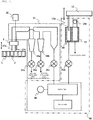
- FIG. 2 is a schematic diagram for illustrating an apparatus configuration for performing waste liquid suction operation.
- an apparatus configuration for suctioning waste liquid will be described.
- the vacuum tank is provided with a vacuum switch 36 for sensing that the pressure in the vacuum tank is reduced to specified negative pressure.
- the control unit 22 determines that analysis is possible.
- the vacuum switch is provided with a pressure receiving portion for receiving pressure and a pressure receiving element for detecting the pressure received by the pressure receiving portion, and is configured with a spring and a switch. When the pressure receiving element senses that the pressure received by the pressure receiving portion reaches a set pressure value, a contact point of the switch is switched by the spring.
- reaction waste liquid suction nozzles 37a, 37b or a cleaning waste liquid suction mechanism 39 is provided, and when solenoid valves 35c, 35d between the vacuum tank and the reaction waste liquid suction nozzles 37a, 37b or the cleaning waste liquid suction mechanism 39 are opened, vacuum suction can be performed.
- Vacuum bottles 34a, 34b for trapping the reaction waste liquid are provided in a flow path of the reaction waste liquid suction nozzles 37a, 37b, and the solenoid valve 35c.
- solenoid valves 35a, 35b connected to the vacuum bottles 34a, 34b are opened, the reaction waste liquid is discharged from the vacuum bottles 34a, 34b.
- the apparatus configuration for suctioning the waste liquid has been described above.
- reaction waste liquid is suctioned by a reaction waste liquid suction mechanism 21.
- the reaction disk 1 rotates and the reaction vessel 2 containing the reaction waste liquid is moved to a position of the cleaning mechanism 3.
- the cleaning mechanism 3 moves down and the reaction waste liquid suction nozzles 37a, 37b enter the inside of the reaction vessel 2, the solenoid valve 35c connected to the vacuum tank is opened and the reaction waste liquid is suctioned.
- the suctioned reaction waste liquid is trapped by the vacuum bottles 34a, 34b, and is discharged to a waste liquid tank or a waste liquid sewage facility outside the apparatus by opening the solenoid valves 35a, 35b.
- the reaction waste liquid suction nozzle 37a high concentration reaction waste liquid in which the sample and the reagent are mixed is suctioned.
- the reaction waste liquid suction nozzle 37b low concentration reaction waste liquid is suctioned in which reaction waste liquid is diluted by a detergent discharged by the detergent discharge mechanism 20 during cleaning operation of the reaction vessel 2 after being suctioned.
- the suction operation of the reaction waste liquid has been described above.
- the cleaning waste liquid is suctioned by a probe cleaning mechanism 40.
- the second sample dispensing mechanism 12 moves the sample probe 12a to the cleaning tank 14. Cleaning water is discharged from a cleaning water discharge mechanism 14a, and the sample adhered to the surface of the sample probe 12a is washed away. Thereafter, the second sample dispensing mechanism 12 moves the sample probe 12a to the cleaning waste liquid suction mechanism 39. Cleaning water remaining on the surface of the sample probe 12a is suctioned by opening the solenoid valve 35d. Since an amount of cleaning water to be suctioned is extremely small, the cleaning water is trapped in the vacuum tank. The suction operation of the cleaning waste liquid is also performed in the cleaning tank 13 for the first sample dispensing mechanism 11. The suction operation of the cleaning waste liquid has been described above.
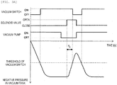
- FIG. 3A a relationship between negative pressure in the vacuum tank and a signal of the vacuum switch when the vacuum tank is opened to the atmosphere without anomaly such as clogging in the flow path connected to the vacuum tank will be described.
- a vertical axis represents the negative pressure in the vacuum tank, and a horizontal axis represents time.
- the vacuum pump is stopped at any time T in a state in which the negative pressure in the vacuum tank is stable, and one of a plurality of solenoid valves connected to the vacuum tank is opened to bring the vacuum tank into an atmosphere open state.
- the negative pressure in the vacuum tank in the atmosphere open state decreases, and when the pressure falls below the threshold of the vacuum switch, the vacuum switch is turned OFF.
- time t n that elapses before the vacuum switch is turned OFF from the any time T is measured.
- the vacuum pump is turned ON and the solenoid valve is closed to make the negative pressure in the vacuum tank constant.
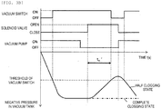
- FIG. 3B a relationship between the negative pressure in the vacuum tank and the opening and closing of the solenoid valve connected to the vacuum tank, the ON/OFF of the vacuum pump, and the signal of the vacuum switch 36 when there is an anomaly such as clogging in the flow path connected to the vacuum tank will be described.
- the vacuum pump is stopped at any time T, and one of the plurality of solenoid valves connected to the vacuum tank is opened to bring the vacuum tank into the atmosphere open state.
- the negative pressure in the vacuum tank in the atmosphere open state decreases more slowly than in the case where there is no clogging, so that time t n ' that elapses before the vacuum switch is turned OFF becomes long. Therefore, since the relationship between the reference values t n and t n ' is t n ⁇ t n ', clogging can be detected.
- the method for determining clogging has been described above.
- FIG. 4A shows a flowchart of determining clogging in the probe cleaning mechanism 40.
- S1 preparation operation, at the start of the flow path clogging determination (S1), all the solenoid valves connected to the vacuum tank are closed (S2) .
- the vacuum pump starts operating (S3), and when the negative pressure in the vacuum tank exceeds a threshold of the vacuum switch, the vacuum switch is turned ON, and the pressure in the vacuum tank becomes constant (S4).
- the vacuum pump is turned OFF (S5).
- the solenoid valve 35c connected to the vacuum tank is opened (S6). Time t 1 that elapses before the vacuum switch is turned OFF is measured (S7), and clogging determination is performed (S8).
- the processing moves to analysis operation (S9).
- a determination result is displayed with an alarm on an operation unit (S10), and the apparatus is stopped (S11). The determination of the clogging is effective even when a plurality of mechanisms that suction cleaning waste liquid are connected to the vacuum tank.
- S1 preparation operation
- all the solenoid valves connected to the vacuum tank are closed (S2) .
- the vacuum pump starts operating (S3), and when the negative pressure in the vacuum tank exceeds the threshold of the vacuum switch, the vacuum switch is turned ON, and the pressure in the vacuum tank becomes constant (S4).
- S5 the vacuum pump is turned OFF (S5).
- a solenoid valve in the flow path corresponding to a reference value t 1 is opened (S16) .
- Time t 1 that elapses before the vacuum switch is turned OFF is measured (S17), and clogging determination is performed (S18).
- a determination result is stored in a storage unit (S25). After the clogging determination, it is confirmed that the opened solenoid valve is closed (S19), the vacuum pump is turned ON, and the vacuum switch is turned ON (S20) . The vacuum pump is stopped and only a solenoid valve corresponding to a reference value t 2 is opened (S21) . Time t 2 ' that elapses before the vacuum switch is turned OFF is measured (S22), and clogging determination is performed (S23) .
- the clogging determination operation and the flowchart are performed at the time of analysis preparation and maintenance.
- the time that elapses before the vacuum switch is turned OFF measured at the time of maintenance is recorded in the apparatus such that the measured time can be compared with a previous value every time the maintenance is performed.
- the clogging determination operation can be used as a preventive maintenance function.
- FIG. 6 shows a relationship between the pressure in the vacuum tank and an altitude when the clogging determination method is used. Since atmospheric pressure is lower in an area at an altitude of 2000 m than that at an altitude of 0 m, the vacuum pump cannot sufficiently draw negative pressure, and there is no margin for the suction operation of the waste liquid using the vacuum. Therefore, when the vacuum pump is stopped in a state in which the negative pressure in the vacuum tank is constant, all the solenoid valves connected to the vacuum tank are opened, and the vacuum tank is opened to the atmosphere, assuming that a reference value until the vacuum switch at an altitude h is turned off is t h , t 0 > t 2000 .
- a reference value t h corresponding to the altitude is set in the apparatus as a value unified for all apparatuses, and time t h ' that elapses before the vacuum switch is turned OFF when the apparatus is installed is measured and is compared with the reference value t h .
- the comparison result is t h > t h ' , since it can be determined that there is no margin for the suction operation of waste liquid using vacuum, it is possible to determine a correspondence such as adding a vacuum pump or replacing the vacuum pump with a vacuum pump capable of drawing a high vacuum degree.
- the reference value t h it is possible to individually set atmosphere open time at the time of analysis completion operation in accordance with the altitude of the installation destination of the apparatus.
- the automatic analyzer it is common to return the pressure inside of the vacuum tank to the atmospheric pressure during the analysis completion operation. This is because if negative pressure remains in the vacuum tank, the vacuum pump is always applied with negative pressure, a load is applied to actuate the diaphragm from a negative pressure state when the vacuum pump is started, and deterioration of the vacuum pump is accelerated.
- the reference value t h as the time required to return the pressure in the vacuum tank to the atmospheric pressure according to the altitude can be set as the atmosphere open time of the analysis completion operation. Accordingly, waiting time of an operator can be shortened by completing the analysis completion operation at appropriate time.
Landscapes
- Physics & Mathematics (AREA)
- General Physics & Mathematics (AREA)
- Health & Medical Sciences (AREA)
- Life Sciences & Earth Sciences (AREA)
- Chemical & Material Sciences (AREA)
- Analytical Chemistry (AREA)
- Biochemistry (AREA)
- General Health & Medical Sciences (AREA)
- Immunology (AREA)
- Pathology (AREA)
- Electromagnetism (AREA)
- Automatic Analysis And Handling Materials Therefor (AREA)
Abstract
Description
- The present invention relates to an automatic analyzer, and a method for detecting flow path clogging of the automatic analyzer.
- An automatic analyzer discharges a certain amount of sample and a certain amount of reagent into a reaction vessel, mixes the sample and the reagent to cause reaction, and analyzes a component, a concentration, and the like of the sample by optically measuring reaction liquid.
- After completion of the analysis, since reaction waste liquid in which the sample and the reagent are reacted is generated in the reaction vessel, the waste liquid is suctioned using a vacuum pump or the like in order to remove the reaction waste liquid from the reaction vessel. In addition, in the automatic analyzer that performs qualitative and quantitative analysis of the sample, by appropriately cleaning a probe used for dispensing the sample to be analyzed, occurrence of cross contamination is prevented and analysis accuracy is maintained, and a cleaning liquid suction mechanism that removes cleaning liquid or the like adhered to a probe surface is also provided.
- Patent Literature 1:
WO 07/132632 - The automatic analyzer having a plurality of mechanisms including a mechanism for suctioning the reaction waste liquid and a mechanism for suctioning the cleaning liquid and the like adhered to the surface after probe cleaning, reduces pressure in a vacuum tank by a pressure-reducing pump or the like, arranges a solenoid valve in a flow path from the vacuum tank, opens and closes the solenoid valve, and suctions the waste liquid by a pressure difference in the vacuum tank. When the pressure in the vacuum tank reaches specified negative pressure, a contact point of a vacuum switch provided in the vacuum tank is switched and then the analyzer becomes ready for analysis. When a flow path portion of each mechanism connected to the vacuum tank is clogged or an operation failure occurs in the solenoid valve, the suction operation cannot be performed normally, and there is a high possibility that the analysis performance will be affected due to such as waste liquid remaining in the reaction vessel or remaining cleaning water adhered to a probe. In the automatic analyzer disclosed in
Patent Literature 1, an individual pressure sensor is installed in a suction nozzle in order to detect clogging of a drainage system of a waste liquid suction unit. In this case, the pressure sensor is required for all of the waste liquid suction units, and the risk of failure increases as the number of sensors increases. Further, in an existing apparatus that does not have a pressure sensor, when a clogging detection function is to be newly added, an installation location of the pressure sensor is limited, and an apparatus configuration is complicated. - An object of the invention is to provide an automatic analyzer capable of detecting clogging in a flow path and a method for detecting flow path clogging of the automatic analyzer.
- To solve the above problems, an automatic analyzer of the invention includes a vacuum tank and a vacuum pump that vacuum suctions liquid; a first solenoid valve provided in a flow path connected to the vacuum tank; a determination unit that determines whether a vacuum value in the vacuum tank is equal to or greater than a predetermined threshold, or whether the vacuum value is smaller than the predetermined threshold; and a clogging detection unit that detects clogging in the flow path. The clogging detection unit changes the vacuum pump from ON to OFF with the first solenoid valve being in a closed state, and thereafter, changes the first solenoid valve from the closed state to an open state, and detects presence and absence of clogging in the flow path by comparing time that elapses before the determination unit determines that the vacuum value in the vacuum tank is equal to or greater than the predetermined threshold from a time point when the first solenoid valve is changed from the closed state to the open state, to a predetermined threshold.
- In order to solve the above problems, with a solenoid valve arranged between a vacuum tank and a mechanism requiring vacuum being in a closed state, a vacuum pump is operated until negative pressure of the vacuum tank becomes constant, and then the vacuum pump is stopped. A negative pressure value in the vacuum tank is held at a constant negative pressure value unless there is a normal leak. If the vacuum switch is turned OFF at a certain time, a leak occurs somewhere in the flow path. Therefore, in order to confirm whether there is a leak in each flow path system, the vacuum pump is stopped when the negative pressure of the vacuum tank is constant, the solenoid valve in the flow path at a part desired to be confirmed and connected to the vacuum tank is opened, and time that elapses before the vacuum switch is turned OFF is measured, and presence and absence of an anomaly in the flow path system is determined by comparing the measured time with a threshold. By performing the above-described determination in all the flow paths using vacuum, presence and absence of an anomaly in the flow path system is determined.
- According to the invention, when there is an anomaly in the flow path, the anomaly of the flow path can be detected without using a sensor for measuring the pressure.
-
- [
FIG. 1] FIG. 1 is a diagram showing an outline of an automatic analyzer according to an embodiment of the invention. - [
FIG. 2] FIG. 2 is a schematic diagram illustrating a connection between a waste liquid suction mechanism and a vacuum tank according to the embodiment of the invention. - [
FIG. 3A] FIG. 3A is a diagram showing waveforms of, when the suction mechanism is normal without clogging, pressure, opening and closing of a solenoid valve, ON/OFF of a vacuum pump and a signal of a vacuum switch at a time of suctioning the waste liquid. - [
FIG. 3B] FIG. 3B is a diagram showing waveforms of, when the suction mechanism is clogged, the pressure, the opening and closing of the solenoid valve, the ON/OFF of the vacuum pump, and the signal of the vacuum switch at the time of suctioning the waste liquid. - [
FIG. 4A] FIG. 4A is a diagram showing a flowchart of determining clogging in a mechanism that suctions cleaning waste liquid. - [
FIG. 4B] FIG. 4B is a diagram showing a flowchart of determining clogging when the mechanism that suctions the cleaning waste liquid is connected to n or more (n = 2) vacuum tanks. - [
FIG. 5] FIG. 5 shows a flowchart of determining clogging when a flow path between a solenoid valve and a nozzle connected to the vacuum tank in a mechanism that suctions reaction waste liquid is branched. - [
FIG. 6] FIG. 6 shows a relationship between pressure in the vacuum tank and an altitude when a clogging determination method is used. - In an automatic analyzer of the invention, with a solenoid valve arranged between a vacuum tank and a mechanism requiring vacuum being in a closed state, a vacuum pump is operated until negative pressure of the vacuum tank becomes constant, and then the vacuum pump is stopped. A negative pressure value in the vacuum tank is held at a constant negative pressure value unless there is a normal leak. If a vacuum switch is turned OFF at a certain time, a leak occurs somewhere in the flow path. Therefore, in order to confirm whether there is a leak in each flow path system, the vacuum pump is stopped when the negative pressure of the vacuum tank is constant, the solenoid valve in the flow path at a part desired to be confirmed and connected to the vacuum tank is opened, and time that elapses before the vacuum switch is turned OFF is measured, and presence and absence of an anomaly in the flow path system is determined by comparing the measured time with a threshold. By performing the above-described determination in all the flow paths using vacuum, presence and absence of an anomaly in the flow path system is determined.
- Hereinafter, an embodiment of an automatic analyzer and a method for cleaning a dispensing probe of the invention will be described in detail with reference to
FIGS. 1 to 6 . - First, an overall configuration of an automatic analyzer will be described with reference to
FIG. 1. FIG. 1 is a diagram schematically showing the overall configuration of the automatic analyzer according to the present embodiment. - In
FIG. 1 , anautomatic analyzer 100 is an apparatus that dispenses a sample and a reagent into areaction vessel 2 separately to cause reaction, and measures the reacted liquid, and a schematic configuration of theautomatic analyzer 100 includes asample transport mechanism 17, areagent disk 9, areaction disk 1, a firstsample dispensing mechanism 11, a secondsample dispensing mechanism 12,reagent dispensing mechanisms 7, 8,stirring mechanisms spectrophotometer 4, acleaning mechanism 3, and acontrol unit 22. - In the
reaction disk 1, thereaction vessels 2 are arranged in a circumferential direction. Thereaction vessel 2 is a vessel for accommodating mixed liquid in which the sample and the reagent are mixed, and a plurality ofreaction vessels 2 are arranged on thereaction disk 1. In a vicinity of thereaction disk 1, thesample transport mechanism 17 that transports asample rack 16 on which one ormore sample vessels 15 accommodating a sample to be analyzed are mounted is arranged. - The first
sample dispensing mechanism 11 and the secondsample dispensing mechanism 12 capable of rotating and moving up and down are arranged between thereaction disk 1 and thesample transport mechanism 17. - The first
sample dispensing mechanism 11 has asample probe 11a arranged with a tip thereof being directed downward, and asample pump 19 is connected to thesample probe 11a. The firstsample dispensing mechanism 11 is configured to be capable of discharging cleaning water (hereinafter referred to as "internal cleaning water"), sent from a cleaning water tank (not shown) by thesample pump 19, from thesample probe 11a. The firstsample dispensing mechanism 11 is configured to be capable of horizontally rotating and moving up and down, inserts thesample probe 11a into thesample vessel 15 to suction the sample by operating thesample pump 19, and inserts thesample probe 11a into thereaction vessel 2 to discharge the sample. Thus, the sample is dispensed from thesample vessel 15 to thereaction vessel 2. In an operating range of the firstsample dispensing mechanism 11, acleaning tank 13 for cleaning thesample probe 11a with cleaning liquid and acleaning vessel 23 for cleaning thesample probe 11a with special cleaning liquid are arranged. When a position where thesample probe 11a is inserted into thesample vessel 15 and the sample is suctioned is set as a first sample suction position, and a position where thesample probe 11a is inserted into thereaction vessel 2 and the sample is discharged is set as a first sample discharge position, thecleaning tank 13 and thecleaning vessel 23 are arranged between the first sample suction position and the first sample discharge position. - The second
sample dispensing mechanism 12 has asample probe 12a arranged with a tip thereof being directed downward, and thesample pump 19 is connected to thesample probe 12a. The secondsample dispensing mechanism 12 is configured to be capable of discharging cleaning water (internal cleaning water), sent from the cleaning water tank (not shown) by thesample pump 19, from thesample probe 12a. The secondsample dispensing mechanism 12 is configured to be capable of horizontally rotating and moving up and down, inserts thesample probe 12a into thesample vessel 15 to suction the sample by operating thesample pump 19, and inserts thesample probe 12a into thereaction vessel 2 to discharges the sample. Thus, the sample is dispensed from thesample vessel 15 to thereaction vessel 2. In an operating range of the secondsample dispensing mechanism 12, acleaning tank 14 for cleaning thesample probe 12a with cleaning liquid and a cleaningvessel 24 for cleaning thesample probe 12a with special cleaning liquid are arranged. When a position where thesample probe 12a is inserted into thesample vessel 15 and the sample is suctioned is set as a second sample suction position, and a position where thesample probe 12a is inserted into thereaction vessel 2 and the sample is discharged is set as a second sample discharge position, thecleaning tank 14 and the cleaningvessel 24 are arranged between the second sample suction position and the second sample discharge position. - The cleaning
tanks cleaning vessels - The
reagent disk 9 is a storage container on which a plurality ofreagent bottles 10 each accommodating a reagent therein can be placed on a circumference. Thereagent disk 9 is kept cool. - The
reagent dispensing mechanisms 7, 8 for dispensing the reagent from thereagent bottle 10 to thereaction vessel 2 are provided, which are configured to be capable of horizontally rotating and moving up and down between thereaction disk 1 and thereagent disk 9, and thereagent dispensing mechanisms 7, 8 respectively includereagent probes reagent pump 18 is connected to the reagent probes 7a, 8a. A reagent, a detergent, a diluent, a pretreatment reagent, and the like suctioned from thereagent bottle 10 and the like are dispensed via the reagent probes 7a, 8a into thereaction vessel 2 by thereagent pump 18. - In an operating range of the reagent dispensing mechanism 7, a
cleaning tank 32 for cleaning thereagent probe 7a with cleaning liquid is arranged. In an operating range of thereagent dispensing mechanism 8, a cleaning tank 33 for cleaning thereagent probe 8a with cleaning liquid is arranged. - Around the
reaction disk 1, the stirringmechanisms spectrophotometer 4 that measures absorbance of a reaction liquid by measuring transmitted light obtained from the light source 4a via the reaction liquid in thereaction vessel 2, and thecleaning mechanism 3 that cleans the usedreaction vessel 2 and the like are arranged. - The stirring
mechanisms reaction vessel 2 to stir the mixed liquid (reaction liquid) of the sample and the reagent. In operating ranges of the stirringmechanisms tanks mechanisms detergent discharge mechanism 20 is connected to thecleaning mechanism 3. - The
control unit 22 is configured by a computer or the like, controls operation of each of the mechanisms described above in the automatic analyzer, and performs calculation processing for obtaining a concentration of a predetermined component in a liquid sample such as blood or urine. InFIG. 1 , for the sake of simplicity, a part of the connection between the mechanisms of the automatic analyzer and thecontrol unit 22 is omitted. - The general configuration of the
automatic analyzer 100 has been described above. Analysis processing of an examination sample by theautomatic analyzer 100 as described above is generally performed in the following order. - First, a sample in the
sample vessel 15 placed on thesample rack 16 transported to the vicinity of thereaction disk 1 by thesample transport mechanism 17 is dispensed into thereaction vessel 2 on thereaction disk 1 by thesample probe 11a of the firstsample dispensing mechanism 11 or thesample probe 12a of the secondsample dispensing mechanism 12. Next, a reagent to be used for analysis is dispensed from thereagent bottle 10 on thereagent disk 9 to thereaction vessel 2, in which the sample is previously dispensed, by the reagent probes 7a, 8a of thereagent dispensing mechanisms 7, 8. Subsequently, a mixed liquid of the sample and the reagent in thereaction vessel 2 is stirred by the stirringmechanisms reaction vessel 2 containing the mixed liquid, and light intensity of the transmitted light is measured by thespectrophotometer 4. The light intensity measured by thespectrophotometer 4 is transmitted to thecontrol unit 22 via an A/D converter and an interface. Then, a calculation is performed by thecontrol unit 22 to obtain a concentration of a predetermined component of the analysis item according to the reagent, and a result is displayed on a display unit (not shown) and stored in a storage unit (not shown). -
FIG. 2 is a schematic diagram for illustrating an apparatus configuration for performing waste liquid suction operation. First, an apparatus configuration for suctioning waste liquid will be described. When the vacuum pump is operated, pressure in the vacuum tank connected to the vacuum pump is reduced. The vacuum tank is provided with avacuum switch 36 for sensing that the pressure in the vacuum tank is reduced to specified negative pressure. When the specified negative pressure is reached and the vacuum switch is turned ON, thecontrol unit 22 determines that analysis is possible. The vacuum switch is provided with a pressure receiving portion for receiving pressure and a pressure receiving element for detecting the pressure received by the pressure receiving portion, and is configured with a spring and a switch. When the pressure receiving element senses that the pressure received by the pressure receiving portion reaches a set pressure value, a contact point of the switch is switched by the spring. At an end of the flow path connected to the vacuum tank, reaction wasteliquid suction nozzles liquid suction mechanism 39 is provided, and whensolenoid valves liquid suction nozzles liquid suction mechanism 39 are opened, vacuum suction can be performed.Vacuum bottles liquid suction nozzles solenoid valve 35c. Whensolenoid valves vacuum bottles vacuum bottles - Next, suction operation of the reaction waste liquid will be described. The reaction waste liquid is suctioned by a reaction waste
liquid suction mechanism 21. After completion of the analysis, since the reaction waste liquid in which the sample and the reagent are reacted remains in thereaction vessel 2, thereaction disk 1 rotates and thereaction vessel 2 containing the reaction waste liquid is moved to a position of thecleaning mechanism 3. When thecleaning mechanism 3 moves down and the reaction wasteliquid suction nozzles reaction vessel 2, thesolenoid valve 35c connected to the vacuum tank is opened and the reaction waste liquid is suctioned. The suctioned reaction waste liquid is trapped by thevacuum bottles solenoid valves liquid suction nozzle 37a, high concentration reaction waste liquid in which the sample and the reagent are mixed is suctioned. In the reaction wasteliquid suction nozzle 37b, low concentration reaction waste liquid is suctioned in which reaction waste liquid is diluted by a detergent discharged by thedetergent discharge mechanism 20 during cleaning operation of thereaction vessel 2 after being suctioned. The suction operation of the reaction waste liquid has been described above. - Next, suction operation of the cleaning waste liquid will be described. The cleaning waste liquid is suctioned by a
probe cleaning mechanism 40. After dispensing, the secondsample dispensing mechanism 12 moves thesample probe 12a to thecleaning tank 14. Cleaning water is discharged from a cleaningwater discharge mechanism 14a, and the sample adhered to the surface of thesample probe 12a is washed away. Thereafter, the secondsample dispensing mechanism 12 moves thesample probe 12a to the cleaning wasteliquid suction mechanism 39. Cleaning water remaining on the surface of thesample probe 12a is suctioned by opening thesolenoid valve 35d. Since an amount of cleaning water to be suctioned is extremely small, the cleaning water is trapped in the vacuum tank. The suction operation of the cleaning waste liquid is also performed in thecleaning tank 13 for the firstsample dispensing mechanism 11. The suction operation of the cleaning waste liquid has been described above. - In the above configuration, a method for detecting an anomaly such as clogging in a plurality of flow paths connected to the vacuum tank will be described. First, in
FIG. 3A , a relationship between negative pressure in the vacuum tank and a signal of the vacuum switch when the vacuum tank is opened to the atmosphere without anomaly such as clogging in the flow path connected to the vacuum tank will be described. A vertical axis represents the negative pressure in the vacuum tank, and a horizontal axis represents time. When the vacuum pump is turned ON, the pressure in the vacuum tank is reduced. When a threshold of the vacuum switch is reached, thevacuum switch 36 is turned ON. The vacuum pump is stopped at any time T in a state in which the negative pressure in the vacuum tank is stable, and one of a plurality of solenoid valves connected to the vacuum tank is opened to bring the vacuum tank into an atmosphere open state. The negative pressure in the vacuum tank in the atmosphere open state decreases, and when the pressure falls below the threshold of the vacuum switch, the vacuum switch is turned OFF. At this time, time tn that elapses before the vacuum switch is turned OFF from the any time T is measured. After the measurement is completed, the vacuum pump is turned ON and the solenoid valve is closed to make the negative pressure in the vacuum tank constant. The above measurement is performed n times for n solenoid valves connected to the vacuum tank (n = 1, 2..., n), and is set in the storage unit as a reference value tn when there is no clogging in each flow path. Since the reference value tn is measured and determined at the time of shipment of the apparatus, an individual difference such as an inner diameter of a tube constituting the solenoid valve or the flow path is offset. Therefore, the setting of the reference value tn is a condition that the measurement is performed with a new flow path configuration. - Next, in
FIG. 3B , a relationship between the negative pressure in the vacuum tank and the opening and closing of the solenoid valve connected to the vacuum tank, the ON/OFF of the vacuum pump, and the signal of thevacuum switch 36 when there is an anomaly such as clogging in the flow path connected to the vacuum tank will be described. As inFIG. 3A , the vacuum pump is stopped at any time T, and one of the plurality of solenoid valves connected to the vacuum tank is opened to bring the vacuum tank into the atmosphere open state. When the flow path is clogged, the negative pressure in the vacuum tank in the atmosphere open state decreases more slowly than in the case where there is no clogging, so that time tn' that elapses before the vacuum switch is turned OFF becomes long. Therefore, since the relationship between the reference values tn and tn' is tn < tn', clogging can be detected. The method for determining clogging has been described above. -
FIG. 4A shows a flowchart of determining clogging in theprobe cleaning mechanism 40. As preparation operation, at the start of the flow path clogging determination (S1), all the solenoid valves connected to the vacuum tank are closed (S2) . The vacuum pump starts operating (S3), and when the negative pressure in the vacuum tank exceeds a threshold of the vacuum switch, the vacuum switch is turned ON, and the pressure in the vacuum tank becomes constant (S4). At any time T, the vacuum pump is turned OFF (S5). As determination operation, thesolenoid valve 35c connected to the vacuum tank is opened (S6). Time t1 that elapses before the vacuum switch is turned OFF is measured (S7), and clogging determination is performed (S8). When it is determined that there is no clogging, the processing moves to analysis operation (S9). When it is determined that there is clogging, a determination result is displayed with an alarm on an operation unit (S10), and the apparatus is stopped (S11). The determination of the clogging is effective even when a plurality of mechanisms that suction cleaning waste liquid are connected to the vacuum tank. -
FIG. 4B is a flowchart when the mechanism that suctions the cleaning waste liquid is connected to n or more (n = 2) vacuum tanks. As inFIG. 4A , as preparation operation, at the start of the flow path clogging determination (S1), all the solenoid valves connected to the vacuum tank are closed (S2) . The vacuum pump starts operating (S3), and when the negative pressure in the vacuum tank exceeds the threshold of the vacuum switch, the vacuum switch is turned ON, and the pressure in the vacuum tank becomes constant (S4). At any time T, the vacuum pump is turned OFF (S5). As determination operation, a solenoid valve in the flow path corresponding to a reference value t1 is opened (S16) . Time t1 that elapses before the vacuum switch is turned OFF is measured (S17), and clogging determination is performed (S18). A determination result is stored in a storage unit (S25). After the clogging determination, it is confirmed that the opened solenoid valve is closed (S19), the vacuum pump is turned ON, and the vacuum switch is turned ON (S20) . The vacuum pump is stopped and only a solenoid valve corresponding to a reference value t2 is opened (S21) . Time t2' that elapses before the vacuum switch is turned OFF is measured (S22), and clogging determination is performed (S23) . By repeating the series of operation n times, clogging determination is performed for each flow path connected to the vacuum tank (S24), and a determination result is displayed (S26) . When there is no clogging, the processing moves to the analysis operation (S27). When there is clogging, an alarm is displayed and the apparatus is stopped (S28). -
FIG. 5 shows a flowchart of determining clogging when there are n or more (n = 2) solenoid valves branched before thesolenoid valve 35c connected to the vacuum tank as in the reaction wasteliquid suction mechanism 21. As preparation operation, at the start of the flow path clogging determination (S1), all the solenoid valves connected to the vacuum tank are closed (S2). The vacuum pump starts operating (S3), and when the negative pressure in the vacuum tank exceeds the threshold of the vacuum switch, the vacuum switch is turned ON, and the pressure in the vacuum tank becomes constant (S4). At any time T, the vacuum pump is turned OFF (S5). As determination operation, only thesolenoid valve 35c connected to the vacuum tank is opened (S36). Time that elapses before the vacuum switch is turned OFF is measured (S37), and the clogging determination is performed (S38). When there is no clogging, the processing moves to the analysis operation (S30). When there is clogging, the opened solenoid valve is closed (S39), and it is confirmed that the vacuum pump is turned ON, and the vacuum switch is turned ON (S40). The vacuum pump is turned OFF, and thesolenoid valve 35c and one of the branched solenoid valves (solenoid valve 35a) are simultaneously opened (S41). Time that elapses before the vacuum switch is turned OFF is measured (S42), and the clogging determination is performed (S43). By repeating the series of operation n times, the clogging determination is performed for each of the branched flow paths (S44), and the determination result is displayed with an alarm (S46), and the apparatus is stopped (S47). - The clogging determination operation and the flowchart are performed at the time of analysis preparation and maintenance. In particular, the time that elapses before the vacuum switch is turned OFF measured at the time of maintenance is recorded in the apparatus such that the measured time can be compared with a previous value every time the maintenance is performed. By recording the measured time that elapses before the vacuum switch is turned off from the time of shipment, deterioration of each flow path can be grasped, and the clogging determination operation can be used as a preventive maintenance function.
-
FIG. 6 shows a relationship between the pressure in the vacuum tank and an altitude when the clogging determination method is used. Since atmospheric pressure is lower in an area at an altitude of 2000 m than that at an altitude of 0 m, the vacuum pump cannot sufficiently draw negative pressure, and there is no margin for the suction operation of the waste liquid using the vacuum. Therefore, when the vacuum pump is stopped in a state in which the negative pressure in the vacuum tank is constant, all the solenoid valves connected to the vacuum tank are opened, and the vacuum tank is opened to the atmosphere, assuming that a reference value until the vacuum switch at an altitude h is turned off is th, t0 > t2000. A reference value th corresponding to the altitude is set in the apparatus as a value unified for all apparatuses, and time th' that elapses before the vacuum switch is turned OFF when the apparatus is installed is measured and is compared with the reference value th. When the comparison result is th > th' , since it can be determined that there is no margin for the suction operation of waste liquid using vacuum, it is possible to determine a correspondence such as adding a vacuum pump or replacing the vacuum pump with a vacuum pump capable of drawing a high vacuum degree. - Further, by using the reference value th, it is possible to individually set atmosphere open time at the time of analysis completion operation in accordance with the altitude of the installation destination of the apparatus. In the automatic analyzer, it is common to return the pressure inside of the vacuum tank to the atmospheric pressure during the analysis completion operation. This is because if negative pressure remains in the vacuum tank, the vacuum pump is always applied with negative pressure, a load is applied to actuate the diaphragm from a negative pressure state when the vacuum pump is started, and deterioration of the vacuum pump is accelerated. When an altitude h of an installation location is input to the apparatus, the reference value th as the time required to return the pressure in the vacuum tank to the atmospheric pressure according to the altitude can be set as the atmosphere open time of the analysis completion operation. Accordingly, waiting time of an operator can be shortened by completing the analysis completion operation at appropriate time.
-
- 1
- reaction disk
- 2
- reaction vessel
- 3
- cleaning mechanism
- 4
- spectrophotometer
- 4a
- light source
- 5, 6
- stirring mechanism
- 7, 8
- reagent dispensing mechanism
- 7a, 8a
- reagent probe
- 9
- reagent disk
- 10
- reagent bottle
- 11
- first sample dispensing mechanism
- 11a
- sample probe
- 12
- second sample dispensing mechanism
- 12a
- sample probe
- 13, 14
- cleaning tank
- 14a
- cleaning water discharge port
- 15, 15a, 15b
- sample vessel
- 16
- sample rack
- 17
- sample transport mechanism
- 18a
- reagent pump
- 19
- sample pump
- 20
- detergent discharge mechanism
- 21
- reaction waste liquid suction mechanism
- 22
- control unit
- 23, 24
- cleaning vessel
- 30, 31, 32, 33
- cleaning tank
- 34a, 34b
- vacuum bottle
- 35a, 35b, 35c, 35d
- solenoid valve
- 36
- vacuum switch
- 37a, 37b
- reaction waste liquid suction nozzle
- 39
- cleaning waste liquid suction mechanism
- 40
- probe cleaning mechanism
- 100
- automatic analyzer
Claims (10)
- An automatic analyzer comprising:a vacuum tank and a vacuum pump that vacuum suctions liquid;a first solenoid valve provided in a flow path connected to the vacuum tank;a determination unit that determines whether a vacuum value in the vacuum tank is equal to or greater than a predetermined threshold, or whether the vacuum value is smaller than the predetermined threshold; anda clogging detection unit that detects clogging in the flow path, whereinthe clogging detection unit:changes the vacuum pump from ON to OFF with the first solenoid valve being in a closed state, andthereafter, changes the first solenoid valve from the closed state to an open state, and detects presence and absence of clogging in the flow path by comparing time that elapses before the determination unit determines that the vacuum value in the vacuum tank is equal to or greater than the predetermined threshold from a time point when the first solenoid valve is changed from the closed state to the open state, to a predetermined threshold.
- The automatic analyzer according to claim 1, further comprising:
a cleaning waste liquid suction mechanism that suctions cleaning liquid on a surface of a sample probe by the vacuum pump, on an opposite side of the first solenoid valve with respect to the vacuum tank. - The automatic analyzer according to claim 2, further comprising:
a cleaning tank that accommodates cleaning liquid for a reagent probe and that is adjacent to the cleaning waste liquid suction mechanism. - The automatic analyzer according to claim 1, wherein
a plurality of combinations of the first solenoid valve and the flow path are provided, and
the clogging detection unit sequentially performs the clogging detection for each flow path by controlling opening and closing of the first solenoid valve. - The automatic analyzer according to claim 1, further comprising:
a waste liquid bottle that accommodates waste liquid from a side closer to the vacuum tank, and a reaction vessel, on an opposite side of the first solenoid valve with respect to the vacuum tank. - The automatic analyzer according to claim 5, wherein
a plurality of waste liquid bottles are provided, and each waste liquid bottle is provided with a second solenoid valve on a discharge side from which waste liquid is discharged, and
a flow path from the reaction vessel to the vacuum tank is provided for each of the waste liquid bottles. - The automatic analyzer according to claim 6, wherein
the clogging detection unit:
when it is determined that the flow path is clogged, closes the first solenoid valve, changes the vacuum pump from OFF to ON, confirms that the vacuum value in the vacuum tank is smaller than the predetermined threshold by the determination unit, thereafter, changes the vacuum pump from ON to OFF, changes the first solenoid valve and any one of the second solenoid valves from the closed state to the open state, and detects presence and absence of the clogging in the flow path by comparing time that elapses before the determination unit determines that the vacuum value in the vacuum tank is equal to or greater than the predetermined threshold from a time point when the valves are changed from the closed state to the open state, to a predetermined threshold. - The automatic analyzer according to claim 7, wherein
which flow path is clogged is detected by sequentially performing operation of changing the first solenoid valve and any one of the second solenoid valves from the closed state to the open state. - The threshold used when the clogging is detected by the determination unit is set based on a height of an altitude at which the apparatus is installed.
- A method for detecting flow path clogging of an automatic analyzer comprising:a vacuum tank and a vacuum pump that vacuum suctions liquid;a first solenoid valve provided in a flow path connected to the vacuum tank;a determination unit that determines whether a vacuum value in the vacuum tank is equal to or greater than a predetermined threshold, or whether the vacuum value is smaller than the predetermined threshold; anda clogging detection unit that detects clogging in the flow path, the method comprising:
the clogging detection unit:changing the vacuum pump from ON to OFF with the first solenoid valve being in a closed state, andthereafter, changing the first solenoid valve from the closed state to an open state, and detecting presence and absence of clogging in the flow path by comparing time that elapses before the determination unit determines that the vacuum value in the vacuum tank is equal to or greater than the predetermined threshold from a time point when the first solenoid valve is changed from the closed state to the open state, to a predetermined threshold.
Applications Claiming Priority (2)
| Application Number | Priority Date | Filing Date | Title |
|---|---|---|---|
| JP2018047432 | 2018-03-15 | ||
| PCT/JP2019/001964 WO2019176295A1 (en) | 2018-03-15 | 2019-01-23 | Automatic analyzing apparatus, and method for detecting flow path clogging of the automatic analyzing apparatus |
Publications (3)
| Publication Number | Publication Date |
|---|---|
| EP3767299A1 true EP3767299A1 (en) | 2021-01-20 |
| EP3767299A4 EP3767299A4 (en) | 2021-12-08 |
| EP3767299B1 EP3767299B1 (en) | 2023-06-07 |
Family
ID=67907101
Family Applications (1)
| Application Number | Title | Priority Date | Filing Date |
|---|---|---|---|
| EP19767024.3A Active EP3767299B1 (en) | 2018-03-15 | 2019-01-23 | Automatic analyzing apparatus, and method for detecting flow path clogging of the automatic analyzing apparatus |
Country Status (5)
| Country | Link |
|---|---|
| US (1) | US11079402B2 (en) |
| EP (1) | EP3767299B1 (en) |
| JP (1) | JP6877629B2 (en) |
| CN (1) | CN111133317B (en) |
| WO (1) | WO2019176295A1 (en) |
Families Citing this family (10)
| Publication number | Priority date | Publication date | Assignee | Title |
|---|---|---|---|---|
| CN111961583B (en) * | 2020-06-17 | 2024-09-10 | 上海仁度生物科技股份有限公司 | Anti-blocking liquid suction device and method for removing blockage of liquid suction device |
| JP7471168B2 (en) * | 2020-07-17 | 2024-04-19 | 株式会社日立ハイテク | Automatic analyzer and method for acquiring gear pump status of automatic analyzer |
| JP7476077B2 (en) * | 2020-11-02 | 2024-04-30 | 日本電子株式会社 | Automatic analysis device and automatic analysis method |
| JP7630354B2 (en) * | 2021-05-21 | 2025-02-17 | 株式会社日立ハイテク | Automated Analysis Equipment |
| US20240278275A1 (en) * | 2021-06-24 | 2024-08-22 | Nordson Corporation | Non-contact ultrasonic nozzle cleaner with closed-loop automatic clog detection |
| CN115184267A (en) * | 2022-07-08 | 2022-10-14 | 上海科华实验系统有限公司 | Peristaltic pump flow detection device and method for chemiluminescence instrument |
| US12104362B1 (en) | 2023-03-22 | 2024-10-01 | Sevee & Maher Engineers, Inc. | Assessing and remediating well clogging from bacteria, systems, apparatuses, and methods |
| WO2025006607A1 (en) * | 2023-06-30 | 2025-01-02 | Beckman Coulter, Inc. | Vacuum monitoring |
| CN120064676A (en) * | 2023-11-28 | 2025-05-30 | 贝克曼库尔特实验系统(苏州)有限公司 | Medical analyzer and method of operating the same |
| CN118731331B (en) * | 2024-07-03 | 2025-07-01 | 中国人民解放军联勤保障部队第九二六医院 | Endocrine detection equipment and detection system based on big data |
Family Cites Families (18)
| Publication number | Priority date | Publication date | Assignee | Title |
|---|---|---|---|---|
| KR870002377A (en) * | 1985-08-05 | 1987-03-31 | 미다 가쓰시게 | Negative pressure supply device for automobile |
| JP3197380B2 (en) | 1993-01-13 | 2001-08-13 | オリンパス光学工業株式会社 | Insufflation device |
| JP3041220B2 (en) * | 1995-07-28 | 2000-05-15 | オリンパス光学工業株式会社 | Insufflation device |
| JP3682138B2 (en) * | 1997-02-13 | 2005-08-10 | アロカ株式会社 | Dispensing device |
| JP3700402B2 (en) * | 1998-07-24 | 2005-09-28 | 富士レビオ株式会社 | Method for detecting clogged suction channel or insufficient suction volume, sample liquid suction device, and dispensing device |
| JP4949389B2 (en) * | 2006-05-11 | 2012-06-06 | ベックマン コールター, インコーポレイテッド | Automatic analyzer |
| WO2007132632A1 (en) | 2006-05-17 | 2007-11-22 | Olympus Corporation | Cleaning equipment and automatic analyzer |
| CH704397A2 (en) * | 2011-01-28 | 2012-07-31 | Tecan Trading Ag | A method for detecting the fillability of a waste of microplate washers. |
| JP6018828B2 (en) * | 2012-07-27 | 2016-11-02 | 株式会社日立ハイテクノロジーズ | Automatic analyzer |
| JP5984584B2 (en) * | 2012-08-28 | 2016-09-06 | 株式会社日立ハイテクノロジーズ | Automatic analyzer |
| EP2891381B1 (en) * | 2012-08-29 | 2018-10-03 | Siemens Healthcare Diagnostics Inc. | Pipettor, reagent, and wash solution heater |
| JP6076108B2 (en) * | 2013-01-31 | 2017-02-08 | 株式会社日立ハイテクノロジーズ | Automatic analyzer |
| JP6261941B2 (en) * | 2013-10-24 | 2018-01-17 | 東芝メディカルシステムズ株式会社 | Automatic analyzer |
| CN105934676B (en) * | 2014-01-27 | 2017-09-22 | 株式会社日立高新技术 | Automatic analysing apparatus |
| JP6316670B2 (en) * | 2014-06-17 | 2018-04-25 | キヤノンメディカルシステムズ株式会社 | Clinical laboratory equipment |
| FR3031388B1 (en) | 2015-01-05 | 2017-08-04 | Soc De Construction D’Equipement De Mecanisations Et De Machines Scemm | SYSTEM FOR DETECTING PARTIAL OR TOTAL OBTRUCTION OF AT LEAST ONE INTERNAL PIPE OF A TOOL |
| JP6567890B2 (en) * | 2015-06-19 | 2019-08-28 | 株式会社日立ハイテクノロジーズ | Automatic analyzer |
| EP3588100B1 (en) * | 2017-02-24 | 2021-12-29 | Hitachi High-Tech Corporation | Automated analyzer |
-
2019
- 2019-01-23 CN CN201980004511.1A patent/CN111133317B/en active Active
- 2019-01-23 WO PCT/JP2019/001964 patent/WO2019176295A1/en not_active Ceased
- 2019-01-23 EP EP19767024.3A patent/EP3767299B1/en active Active
- 2019-01-23 JP JP2020505630A patent/JP6877629B2/en active Active
- 2019-01-23 US US16/645,600 patent/US11079402B2/en active Active
Also Published As
| Publication number | Publication date |
|---|---|
| EP3767299A4 (en) | 2021-12-08 |
| JP6877629B2 (en) | 2021-05-26 |
| US20200278373A1 (en) | 2020-09-03 |
| CN111133317B (en) | 2021-05-04 |
| EP3767299B1 (en) | 2023-06-07 |
| JPWO2019176295A1 (en) | 2020-10-22 |
| WO2019176295A1 (en) | 2019-09-19 |
| US11079402B2 (en) | 2021-08-03 |
| CN111133317A (en) | 2020-05-08 |
Similar Documents
| Publication | Publication Date | Title |
|---|---|---|
| EP3767299B1 (en) | Automatic analyzing apparatus, and method for detecting flow path clogging of the automatic analyzing apparatus | |
| US9599631B2 (en) | Automatic analyzer | |
| EP2293083B1 (en) | Automatic analyzer | |
| JP4152351B2 (en) | Clinical specimen processing apparatus and clinical specimen processing system | |
| US9897624B2 (en) | Automatic analyzer | |
| US9513305B2 (en) | Multiple cleaning stations for a dispensing probe | |
| CN114787634B (en) | Automatic analysis device | |
| WO2010038546A1 (en) | Automatic analyzing system | |
| JP2017009362A (en) | Automatic analyzer | |
| JP6654881B2 (en) | Automatic analyzer and method for determining abnormality of automatic analyzer | |
| US20250035662A1 (en) | Automated Analysis Device | |
| US20240369589A1 (en) | Automatic analysis device | |
| JP5111328B2 (en) | Automatic analyzer | |
| JP5912787B2 (en) | Automatic analyzer | |
| JP3120180U (en) | Automatic analyzer | |
| JP6338898B2 (en) | Automatic analyzer | |
| JP4578518B2 (en) | Clinical specimen processing apparatus and clinical specimen processing system | |
| JP7167037B2 (en) | Abnormal detection method for automatic analyzer and specimen pipetting mechanism | |
| EP4571321A1 (en) | Automatic analysis device and method for adjusting amount of cleaning liquid | |
| JP4713629B2 (en) | Automatic analyzer | |
| JP7471168B2 (en) | Automatic analyzer and method for acquiring gear pump status of automatic analyzer | |
| WO2024150645A1 (en) | Automated analyzing device and method for determining water leakage from same | |
| WO2025169633A1 (en) | Automated analyzing device, and waste liquid unit contamination determination method | |
| CN121488162A (en) | Automatic analysis device | |
| JP2025002374A (en) | Automated Analysis Equipment |
Legal Events
| Date | Code | Title | Description |
|---|---|---|---|
| STAA | Information on the status of an ep patent application or granted ep patent |
Free format text: STATUS: THE INTERNATIONAL PUBLICATION HAS BEEN MADE |
|
| PUAI | Public reference made under article 153(3) epc to a published international application that has entered the european phase |
Free format text: ORIGINAL CODE: 0009012 |
|
| STAA | Information on the status of an ep patent application or granted ep patent |
Free format text: STATUS: REQUEST FOR EXAMINATION WAS MADE |
|
| 17P | Request for examination filed |
Effective date: 20200306 |
|
| AK | Designated contracting states |
Kind code of ref document: A1 Designated state(s): AL AT BE BG CH CY CZ DE DK EE ES FI FR GB GR HR HU IE IS IT LI LT LU LV MC MK MT NL NO PL PT RO RS SE SI SK SM TR |
|
| AX | Request for extension of the european patent |
Extension state: BA ME |
|
| DAV | Request for validation of the european patent (deleted) | ||
| DAX | Request for extension of the european patent (deleted) | ||
| A4 | Supplementary search report drawn up and despatched |
Effective date: 20211105 |
|
| RIC1 | Information provided on ipc code assigned before grant |
Ipc: G01N 35/10 20060101ALI20211029BHEP Ipc: G01N 35/00 20060101AFI20211029BHEP |
|
| GRAP | Despatch of communication of intention to grant a patent |
Free format text: ORIGINAL CODE: EPIDOSNIGR1 |
|
| STAA | Information on the status of an ep patent application or granted ep patent |
Free format text: STATUS: GRANT OF PATENT IS INTENDED |
|
| INTG | Intention to grant announced |
Effective date: 20230223 |
|
| GRAS | Grant fee paid |
Free format text: ORIGINAL CODE: EPIDOSNIGR3 |
|
| GRAA | (expected) grant |
Free format text: ORIGINAL CODE: 0009210 |
|
| STAA | Information on the status of an ep patent application or granted ep patent |
Free format text: STATUS: THE PATENT HAS BEEN GRANTED |
|
| RIN1 | Information on inventor provided before grant (corrected) |
Inventor name: MORI, TAKAMICHI Inventor name: FUKUSHI, YUDAI |
|
| AK | Designated contracting states |
Kind code of ref document: B1 Designated state(s): AL AT BE BG CH CY CZ DE DK EE ES FI FR GB GR HR HU IE IS IT LI LT LU LV MC MK MT NL NO PL PT RO RS SE SI SK SM TR |
|
| REG | Reference to a national code |
Ref country code: GB Ref legal event code: FG4D |
|
| REG | Reference to a national code |
Ref country code: CH Ref legal event code: EP Ref country code: AT Ref legal event code: REF Ref document number: 1576654 Country of ref document: AT Kind code of ref document: T Effective date: 20230615 |
|
| REG | Reference to a national code |
Ref country code: DE Ref legal event code: R096 Ref document number: 602019030404 Country of ref document: DE |
|
| REG | Reference to a national code |
Ref country code: LT Ref legal event code: MG9D |
|
| REG | Reference to a national code |
Ref country code: NL Ref legal event code: MP Effective date: 20230607 |
|
| PG25 | Lapsed in a contracting state [announced via postgrant information from national office to epo] |
Ref country code: SE Free format text: LAPSE BECAUSE OF FAILURE TO SUBMIT A TRANSLATION OF THE DESCRIPTION OR TO PAY THE FEE WITHIN THE PRESCRIBED TIME-LIMIT Effective date: 20230607 Ref country code: NO Free format text: LAPSE BECAUSE OF FAILURE TO SUBMIT A TRANSLATION OF THE DESCRIPTION OR TO PAY THE FEE WITHIN THE PRESCRIBED TIME-LIMIT Effective date: 20230907 Ref country code: ES Free format text: LAPSE BECAUSE OF FAILURE TO SUBMIT A TRANSLATION OF THE DESCRIPTION OR TO PAY THE FEE WITHIN THE PRESCRIBED TIME-LIMIT Effective date: 20230607 |
|
| REG | Reference to a national code |
Ref country code: AT Ref legal event code: MK05 Ref document number: 1576654 Country of ref document: AT Kind code of ref document: T Effective date: 20230607 |
|
| PG25 | Lapsed in a contracting state [announced via postgrant information from national office to epo] |
Ref country code: RS Free format text: LAPSE BECAUSE OF FAILURE TO SUBMIT A TRANSLATION OF THE DESCRIPTION OR TO PAY THE FEE WITHIN THE PRESCRIBED TIME-LIMIT Effective date: 20230607 Ref country code: NL Free format text: LAPSE BECAUSE OF FAILURE TO SUBMIT A TRANSLATION OF THE DESCRIPTION OR TO PAY THE FEE WITHIN THE PRESCRIBED TIME-LIMIT Effective date: 20230607 Ref country code: LV Free format text: LAPSE BECAUSE OF FAILURE TO SUBMIT A TRANSLATION OF THE DESCRIPTION OR TO PAY THE FEE WITHIN THE PRESCRIBED TIME-LIMIT Effective date: 20230607 Ref country code: LT Free format text: LAPSE BECAUSE OF FAILURE TO SUBMIT A TRANSLATION OF THE DESCRIPTION OR TO PAY THE FEE WITHIN THE PRESCRIBED TIME-LIMIT Effective date: 20230607 Ref country code: HR Free format text: LAPSE BECAUSE OF FAILURE TO SUBMIT A TRANSLATION OF THE DESCRIPTION OR TO PAY THE FEE WITHIN THE PRESCRIBED TIME-LIMIT Effective date: 20230607 Ref country code: GR Free format text: LAPSE BECAUSE OF FAILURE TO SUBMIT A TRANSLATION OF THE DESCRIPTION OR TO PAY THE FEE WITHIN THE PRESCRIBED TIME-LIMIT Effective date: 20230908 |
|
| PG25 | Lapsed in a contracting state [announced via postgrant information from national office to epo] |
Ref country code: FI Free format text: LAPSE BECAUSE OF FAILURE TO SUBMIT A TRANSLATION OF THE DESCRIPTION OR TO PAY THE FEE WITHIN THE PRESCRIBED TIME-LIMIT Effective date: 20230607 |
|
| PG25 | Lapsed in a contracting state [announced via postgrant information from national office to epo] |
Ref country code: SK Free format text: LAPSE BECAUSE OF FAILURE TO SUBMIT A TRANSLATION OF THE DESCRIPTION OR TO PAY THE FEE WITHIN THE PRESCRIBED TIME-LIMIT Effective date: 20230607 |
|
| PG25 | Lapsed in a contracting state [announced via postgrant information from national office to epo] |
Ref country code: IS Free format text: LAPSE BECAUSE OF FAILURE TO SUBMIT A TRANSLATION OF THE DESCRIPTION OR TO PAY THE FEE WITHIN THE PRESCRIBED TIME-LIMIT Effective date: 20231007 |
|
| PG25 | Lapsed in a contracting state [announced via postgrant information from national office to epo] |
Ref country code: SM Free format text: LAPSE BECAUSE OF FAILURE TO SUBMIT A TRANSLATION OF THE DESCRIPTION OR TO PAY THE FEE WITHIN THE PRESCRIBED TIME-LIMIT Effective date: 20230607 Ref country code: SK Free format text: LAPSE BECAUSE OF FAILURE TO SUBMIT A TRANSLATION OF THE DESCRIPTION OR TO PAY THE FEE WITHIN THE PRESCRIBED TIME-LIMIT Effective date: 20230607 Ref country code: RO Free format text: LAPSE BECAUSE OF FAILURE TO SUBMIT A TRANSLATION OF THE DESCRIPTION OR TO PAY THE FEE WITHIN THE PRESCRIBED TIME-LIMIT Effective date: 20230607 Ref country code: PT Free format text: LAPSE BECAUSE OF FAILURE TO SUBMIT A TRANSLATION OF THE DESCRIPTION OR TO PAY THE FEE WITHIN THE PRESCRIBED TIME-LIMIT Effective date: 20231009 Ref country code: IS Free format text: LAPSE BECAUSE OF FAILURE TO SUBMIT A TRANSLATION OF THE DESCRIPTION OR TO PAY THE FEE WITHIN THE PRESCRIBED TIME-LIMIT Effective date: 20231007 Ref country code: EE Free format text: LAPSE BECAUSE OF FAILURE TO SUBMIT A TRANSLATION OF THE DESCRIPTION OR TO PAY THE FEE WITHIN THE PRESCRIBED TIME-LIMIT Effective date: 20230607 Ref country code: CZ Free format text: LAPSE BECAUSE OF FAILURE TO SUBMIT A TRANSLATION OF THE DESCRIPTION OR TO PAY THE FEE WITHIN THE PRESCRIBED TIME-LIMIT Effective date: 20230607 Ref country code: AT Free format text: LAPSE BECAUSE OF FAILURE TO SUBMIT A TRANSLATION OF THE DESCRIPTION OR TO PAY THE FEE WITHIN THE PRESCRIBED TIME-LIMIT Effective date: 20230607 |
|
| PG25 | Lapsed in a contracting state [announced via postgrant information from national office to epo] |
Ref country code: PL Free format text: LAPSE BECAUSE OF FAILURE TO SUBMIT A TRANSLATION OF THE DESCRIPTION OR TO PAY THE FEE WITHIN THE PRESCRIBED TIME-LIMIT Effective date: 20230607 |
|
| REG | Reference to a national code |
Ref country code: DE Ref legal event code: R097 Ref document number: 602019030404 Country of ref document: DE |
|
| PLBE | No opposition filed within time limit |
Free format text: ORIGINAL CODE: 0009261 |
|
| STAA | Information on the status of an ep patent application or granted ep patent |
Free format text: STATUS: NO OPPOSITION FILED WITHIN TIME LIMIT |
|
| PG25 | Lapsed in a contracting state [announced via postgrant information from national office to epo] |
Ref country code: DK Free format text: LAPSE BECAUSE OF FAILURE TO SUBMIT A TRANSLATION OF THE DESCRIPTION OR TO PAY THE FEE WITHIN THE PRESCRIBED TIME-LIMIT Effective date: 20230607 |
|
| PG25 | Lapsed in a contracting state [announced via postgrant information from national office to epo] |
Ref country code: SI Free format text: LAPSE BECAUSE OF FAILURE TO SUBMIT A TRANSLATION OF THE DESCRIPTION OR TO PAY THE FEE WITHIN THE PRESCRIBED TIME-LIMIT Effective date: 20230607 |
|
| 26N | No opposition filed |
Effective date: 20240308 |
|
| PG25 | Lapsed in a contracting state [announced via postgrant information from national office to epo] |
Ref country code: SI Free format text: LAPSE BECAUSE OF FAILURE TO SUBMIT A TRANSLATION OF THE DESCRIPTION OR TO PAY THE FEE WITHIN THE PRESCRIBED TIME-LIMIT Effective date: 20230607 Ref country code: IT Free format text: LAPSE BECAUSE OF FAILURE TO SUBMIT A TRANSLATION OF THE DESCRIPTION OR TO PAY THE FEE WITHIN THE PRESCRIBED TIME-LIMIT Effective date: 20230607 |
|
| PG25 | Lapsed in a contracting state [announced via postgrant information from national office to epo] |
Ref country code: MC Free format text: LAPSE BECAUSE OF FAILURE TO SUBMIT A TRANSLATION OF THE DESCRIPTION OR TO PAY THE FEE WITHIN THE PRESCRIBED TIME-LIMIT Effective date: 20230607 |
|
| PG25 | Lapsed in a contracting state [announced via postgrant information from national office to epo] |
Ref country code: MC Free format text: LAPSE BECAUSE OF FAILURE TO SUBMIT A TRANSLATION OF THE DESCRIPTION OR TO PAY THE FEE WITHIN THE PRESCRIBED TIME-LIMIT Effective date: 20230607 |
|
| REG | Reference to a national code |
Ref country code: CH Ref legal event code: PL |
|
| PG25 | Lapsed in a contracting state [announced via postgrant information from national office to epo] |
Ref country code: LU Free format text: LAPSE BECAUSE OF NON-PAYMENT OF DUE FEES Effective date: 20240123 |
|
| GBPC | Gb: european patent ceased through non-payment of renewal fee |
Effective date: 20240123 |
|
| PG25 | Lapsed in a contracting state [announced via postgrant information from national office to epo] |
Ref country code: LU Free format text: LAPSE BECAUSE OF NON-PAYMENT OF DUE FEES Effective date: 20240123 |
|
| PG25 | Lapsed in a contracting state [announced via postgrant information from national office to epo] |
Ref country code: GB Free format text: LAPSE BECAUSE OF NON-PAYMENT OF DUE FEES Effective date: 20240123 |
|
| PG25 | Lapsed in a contracting state [announced via postgrant information from national office to epo] |
Ref country code: BE Free format text: LAPSE BECAUSE OF NON-PAYMENT OF DUE FEES Effective date: 20240131 |
|
| PG25 | Lapsed in a contracting state [announced via postgrant information from national office to epo] |
Ref country code: CH Free format text: LAPSE BECAUSE OF NON-PAYMENT OF DUE FEES Effective date: 20240131 |
|
| PG25 | Lapsed in a contracting state [announced via postgrant information from national office to epo] |
Ref country code: GB Free format text: LAPSE BECAUSE OF NON-PAYMENT OF DUE FEES Effective date: 20240123 Ref country code: CH Free format text: LAPSE BECAUSE OF NON-PAYMENT OF DUE FEES Effective date: 20240131 Ref country code: BE Free format text: LAPSE BECAUSE OF NON-PAYMENT OF DUE FEES Effective date: 20240131 |
|
| REG | Reference to a national code |
Ref country code: BE Ref legal event code: MM Effective date: 20240131 |
|
| PG25 | Lapsed in a contracting state [announced via postgrant information from national office to epo] |
Ref country code: BG Free format text: LAPSE BECAUSE OF FAILURE TO SUBMIT A TRANSLATION OF THE DESCRIPTION OR TO PAY THE FEE WITHIN THE PRESCRIBED TIME-LIMIT Effective date: 20230607 |
|
| PG25 | Lapsed in a contracting state [announced via postgrant information from national office to epo] |
Ref country code: BG Free format text: LAPSE BECAUSE OF FAILURE TO SUBMIT A TRANSLATION OF THE DESCRIPTION OR TO PAY THE FEE WITHIN THE PRESCRIBED TIME-LIMIT Effective date: 20230607 |
|
| PG25 | Lapsed in a contracting state [announced via postgrant information from national office to epo] |
Ref country code: IE Free format text: LAPSE BECAUSE OF NON-PAYMENT OF DUE FEES Effective date: 20240123 |
|
| PG25 | Lapsed in a contracting state [announced via postgrant information from national office to epo] |
Ref country code: IE Free format text: LAPSE BECAUSE OF NON-PAYMENT OF DUE FEES Effective date: 20240123 |
|
| PG25 | Lapsed in a contracting state [announced via postgrant information from national office to epo] |
Ref country code: CY Free format text: LAPSE BECAUSE OF FAILURE TO SUBMIT A TRANSLATION OF THE DESCRIPTION OR TO PAY THE FEE WITHIN THE PRESCRIBED TIME-LIMIT; INVALID AB INITIO Effective date: 20190123 |
|
| PG25 | Lapsed in a contracting state [announced via postgrant information from national office to epo] |
Ref country code: HU Free format text: LAPSE BECAUSE OF FAILURE TO SUBMIT A TRANSLATION OF THE DESCRIPTION OR TO PAY THE FEE WITHIN THE PRESCRIBED TIME-LIMIT; INVALID AB INITIO Effective date: 20190123 |
|
| PG25 | Lapsed in a contracting state [announced via postgrant information from national office to epo] |
Ref country code: TR Free format text: LAPSE BECAUSE OF FAILURE TO SUBMIT A TRANSLATION OF THE DESCRIPTION OR TO PAY THE FEE WITHIN THE PRESCRIBED TIME-LIMIT Effective date: 20230607 |
|
| PGFP | Annual fee paid to national office [announced via postgrant information from national office to epo] |
Ref country code: FR Payment date: 20251217 Year of fee payment: 8 |
|
| PGFP | Annual fee paid to national office [announced via postgrant information from national office to epo] |
Ref country code: DE Payment date: 20251217 Year of fee payment: 8 |