EP3767061A1 - Door drive for a door, especially a piece of furniture or a device, method for operating such a door drive and device comprising at least one such door drive - Google Patents
Door drive for a door, especially a piece of furniture or a device, method for operating such a door drive and device comprising at least one such door drive Download PDFInfo
- Publication number
- EP3767061A1 EP3767061A1 EP19425052.8A EP19425052A EP3767061A1 EP 3767061 A1 EP3767061 A1 EP 3767061A1 EP 19425052 A EP19425052 A EP 19425052A EP 3767061 A1 EP3767061 A1 EP 3767061A1
- Authority
- EP
- European Patent Office
- Prior art keywords
- coupling
- door
- rotation
- relative
- actuating
- Prior art date
- Legal status (The legal status is an assumption and is not a legal conclusion. Google has not performed a legal analysis and makes no representation as to the accuracy of the status listed.)
- Granted
Links
- 238000000034 method Methods 0.000 title claims description 8
- 230000008878 coupling Effects 0.000 claims abstract description 287
- 238000010168 coupling process Methods 0.000 claims abstract description 287
- 238000005859 coupling reaction Methods 0.000 claims abstract description 287
- 239000000463 material Substances 0.000 claims description 6
- 229920002430 Fibre-reinforced plastic Polymers 0.000 claims description 2
- 239000011151 fibre-reinforced plastic Substances 0.000 claims description 2
- 239000007769 metal material Substances 0.000 claims description 2
- 239000004033 plastic Substances 0.000 claims description 2
- 229920003023 plastic Polymers 0.000 claims description 2
- 238000006073 displacement reaction Methods 0.000 description 15
- 230000005540 biological transmission Effects 0.000 description 5
- 230000000694 effects Effects 0.000 description 3
- 238000011161 development Methods 0.000 description 1
- 230000018109 developmental process Effects 0.000 description 1
Images


Classifications
-
- E—FIXED CONSTRUCTIONS
- E05—LOCKS; KEYS; WINDOW OR DOOR FITTINGS; SAFES
- E05F—DEVICES FOR MOVING WINGS INTO OPEN OR CLOSED POSITION; CHECKS FOR WINGS; WING FITTINGS NOT OTHERWISE PROVIDED FOR, CONCERNED WITH THE FUNCTIONING OF THE WING
- E05F15/00—Power-operated mechanisms for wings
- E05F15/60—Power-operated mechanisms for wings using electrical actuators
- E05F15/603—Power-operated mechanisms for wings using electrical actuators using rotary electromotors
- E05F15/611—Power-operated mechanisms for wings using electrical actuators using rotary electromotors for swinging wings
- E05F15/616—Power-operated mechanisms for wings using electrical actuators using rotary electromotors for swinging wings operated by push-pull mechanisms
- E05F15/622—Power-operated mechanisms for wings using electrical actuators using rotary electromotors for swinging wings operated by push-pull mechanisms using screw-and-nut mechanisms
-
- F—MECHANICAL ENGINEERING; LIGHTING; HEATING; WEAPONS; BLASTING
- F16—ENGINEERING ELEMENTS AND UNITS; GENERAL MEASURES FOR PRODUCING AND MAINTAINING EFFECTIVE FUNCTIONING OF MACHINES OR INSTALLATIONS; THERMAL INSULATION IN GENERAL
- F16D—COUPLINGS FOR TRANSMITTING ROTATION; CLUTCHES; BRAKES
- F16D11/00—Clutches in which the members have interengaging parts
- F16D11/02—Clutches in which the members have interengaging parts disengaged by a contact of a part mounted on the clutch with a stationarily-mounted member
- F16D11/04—Clutches in which the members have interengaging parts disengaged by a contact of a part mounted on the clutch with a stationarily-mounted member with clutching members movable only axially
-
- E—FIXED CONSTRUCTIONS
- E05—LOCKS; KEYS; WINDOW OR DOOR FITTINGS; SAFES
- E05Y—INDEXING SCHEME RELATING TO HINGES OR OTHER SUSPENSION DEVICES FOR DOORS, WINDOWS OR WINGS AND DEVICES FOR MOVING WINGS INTO OPEN OR CLOSED POSITION, CHECKS FOR WINGS AND WING FITTINGS NOT OTHERWISE PROVIDED FOR, CONCERNED WITH THE FUNCTIONING OF THE WING
- E05Y2201/00—Constructional elements; Accessories therefore
- E05Y2201/20—Brakes; Disengaging means, e.g. clutches; Holders, e.g. locks; Stops; Accessories therefore
- E05Y2201/214—Disengaging means
- E05Y2201/216—Clutches
-
- E—FIXED CONSTRUCTIONS
- E05—LOCKS; KEYS; WINDOW OR DOOR FITTINGS; SAFES
- E05Y—INDEXING SCHEME RELATING TO HINGES OR OTHER SUSPENSION DEVICES FOR DOORS, WINDOWS OR WINGS AND DEVICES FOR MOVING WINGS INTO OPEN OR CLOSED POSITION, CHECKS FOR WINGS AND WING FITTINGS NOT OTHERWISE PROVIDED FOR, CONCERNED WITH THE FUNCTIONING OF THE WING
- E05Y2201/00—Constructional elements; Accessories therefore
- E05Y2201/60—Suspension or transmission members; Accessories therefore
- E05Y2201/622—Suspension or transmission members elements
- E05Y2201/638—Cams; Ramps
-
- E—FIXED CONSTRUCTIONS
- E05—LOCKS; KEYS; WINDOW OR DOOR FITTINGS; SAFES
- E05Y—INDEXING SCHEME RELATING TO HINGES OR OTHER SUSPENSION DEVICES FOR DOORS, WINDOWS OR WINGS AND DEVICES FOR MOVING WINGS INTO OPEN OR CLOSED POSITION, CHECKS FOR WINGS AND WING FITTINGS NOT OTHERWISE PROVIDED FOR, CONCERNED WITH THE FUNCTIONING OF THE WING
- E05Y2800/00—Details, accessories and auxiliary operations not otherwise provided for
- E05Y2800/20—Combinations of elements
- E05Y2800/23—Combinations of elements of elements of different categories
- E05Y2800/238—Combinations of elements of elements of different categories of springs and transmissions
-
- E—FIXED CONSTRUCTIONS
- E05—LOCKS; KEYS; WINDOW OR DOOR FITTINGS; SAFES
- E05Y—INDEXING SCHEME RELATING TO HINGES OR OTHER SUSPENSION DEVICES FOR DOORS, WINDOWS OR WINGS AND DEVICES FOR MOVING WINGS INTO OPEN OR CLOSED POSITION, CHECKS FOR WINGS AND WING FITTINGS NOT OTHERWISE PROVIDED FOR, CONCERNED WITH THE FUNCTIONING OF THE WING
- E05Y2900/00—Application of doors, windows, wings or fittings thereof
- E05Y2900/20—Application of doors, windows, wings or fittings thereof for furnitures, e.g. cabinets
-
- E—FIXED CONSTRUCTIONS
- E05—LOCKS; KEYS; WINDOW OR DOOR FITTINGS; SAFES
- E05Y—INDEXING SCHEME RELATING TO HINGES OR OTHER SUSPENSION DEVICES FOR DOORS, WINDOWS OR WINGS AND DEVICES FOR MOVING WINGS INTO OPEN OR CLOSED POSITION, CHECKS FOR WINGS AND WING FITTINGS NOT OTHERWISE PROVIDED FOR, CONCERNED WITH THE FUNCTIONING OF THE WING
- E05Y2900/00—Application of doors, windows, wings or fittings thereof
- E05Y2900/30—Application of doors, windows, wings or fittings thereof for domestic appliances
- E05Y2900/31—Application of doors, windows, wings or fittings thereof for domestic appliances for refrigerators
-
- E05Y2999/00—
-
- F—MECHANICAL ENGINEERING; LIGHTING; HEATING; WEAPONS; BLASTING
- F16—ENGINEERING ELEMENTS AND UNITS; GENERAL MEASURES FOR PRODUCING AND MAINTAINING EFFECTIVE FUNCTIONING OF MACHINES OR INSTALLATIONS; THERMAL INSULATION IN GENERAL
- F16D—COUPLINGS FOR TRANSMITTING ROTATION; CLUTCHES; BRAKES
- F16D23/00—Details of mechanically-actuated clutches not specific for one distinct type
- F16D23/12—Mechanical clutch-actuating mechanisms arranged outside the clutch as such
- F16D2023/123—Clutch actuation by cams, ramps or ball-screw mechanisms
Definitions
- the invention relates to a door drive according to the preamble of patent claim 1, a method for operating such a door drive according to the preamble of patent claim 13 and a device with at least one such door drive.
- the EP 2 148 035 A2 discloses an arrangement with a housing, in particular a refrigerator and / or freezer.
- the arrangement further comprises a door articulated on the housing so as to be pivotable about a pivot axis of a hinge and at least one drive device for pivoting the door relative to the housing.
- the drive device comprises a drive unit, by means of which a torque with respect to the hinge axis can be exerted on the door via at least one force transmission means.
- the object of the present invention is to create a door drive for a door, in particular a method for operating such a door drive and a device so that the door can be moved in a particularly advantageous manner.
- a first aspect of the invention relates to a door drive for a door, in particular a piece of furniture or an, in particular electrical or electronic, device.
- the device is preferably a refrigerator and / or freezer. This means that the device or the piece of furniture is in its completely manufactured state
- a housing element also referred to as a body
- the aforementioned door which, in particular via at least one hinge, can be moved, in particular pivoted, is held on the housing element and is thus pivotable relative to the housing element, while the door, in particular via the hinge, with is connected to the housing element.
- the door drive is used or can be used to move the door relative to the housing element, in particular to pivot it.
- the door can be opened and / or closed by means of the door drive.
- the door drive has a drive motor, which is preferably designed as an electric motor and can thus be operated electrically or by means of electrical energy or electrical current.
- the door drive also has a drive shaft that can be driven by the drive motor and thereby, in particular, rotatable about a shaft axis of rotation.
- the drive motor has, for example, a stator and a rotor that can be driven by the stator and thus rotatable about a motor axis of rotation relative to the stator, the shaft being driven, for example, by the rotor.
- the shaft is part of the rotor or is connected to the rotor in a rotationally fixed manner.
- the shaft is arranged coaxially to the rotor so that the motor axis of rotation and the shaft axis of rotation coincide.
- the door drive also has a coupling and a threaded spindle, which can be driven by the drive shaft via the coupling and thus rotatable, in particular about a spindle axis of rotation.
- the threaded spindle also referred to simply as a spindle, is preferably arranged coaxially to the shaft, so that the spindle axis of rotation coincides with the shaft axis of rotation.
- the spindle is preferably arranged coaxially with the drive motor or with the rotor, so that, for example, the spindle axis of rotation coincides with the motor axis of rotation.
- the drive shaft, the threaded spindle and possibly the rotor can be rotated relative to a housing of the door drive, for example.
- the housing of the door drive can be the housing element of the device, or the housing is formed separately from the housing element and provided in addition thereto Housing which, for example, can be fastened, in particular fixed, at least indirectly, in particular directly, to the housing element.
- the threaded spindle has, for example, a first thread, in particular in the form of an external thread.
- a screw element is provided, for example, which has, for example, a second thread that corresponds to the first thread and is designed, for example, as an internal thread.
- the screw element is, for example, a nut and can be screwed onto the threaded spindle.
- the door can be driven via the threaded spindle and can thereby be moved relative to the housing element. If, for example, the threaded spindle is rotated relative to the screw element, in particular by means of the drive motor via the coupling, the first thread and the second thread convert the relative rotation between the threaded spindle and the screw element into a translational movement of the screw element, its translational movement along the threaded spindle and takes place in particular along the spindle axis of rotation and relative to the housing.
- the screw element is secured against rotation about the spindle axis of rotation and relative to the housing, or such a rotation of the screw element about the spindle axis of rotation relative to the housing is at least limited, so that when the threaded spindle is rotated about the spindle axis of rotation, the screw element does not is rotated with the threaded spindle, but there is a relative rotation between the threaded spindle and the screw element.
- the screw element is displaced along the threaded spindle and in particular relative to the housing, as a result of which, for example, the door can be moved relative to the housing element.
- the door can be driven by the threaded spindle via the screw element and moved, in particular pivoted, relative to the housing element.
- the coupling is designed as a drive plate, for example Has driver element.
- the clutch also has an actuating element which can be driven by the drive shaft by rotating the drive shaft and thereby is rotatable about an actuating axis of rotation, in particular relative to the housing.
- the actuating element is preferably arranged coaxially to the drive shaft, so that the actuating axis of rotation coincides with the axis of rotation of the shaft.
- the actuation element has at least one first actuation area.
- the clutch also includes a clutch element, which can be designed as a clutch disc, for example.
- the coupling element has at least one second actuation area corresponding to the first actuation area and is translationally movable, i.e. displaceable, along the actuation axis of rotation relative to the driver element and in particular relative to the housing between at least one decoupling position and at least one coupling position.
- the coupling element In the decoupling position, the coupling element is decoupled from the driver element, so that in the decoupling position no torques can be transmitted between the coupling element and the driver element.
- the coupling element is at a distance, in particular completely, from the driver element, in particular at least along the actuation axis of rotation.
- the coupling element In the coupling position, the coupling element is coupled to the driver element, in particular in a torque-transmitting manner, so that in the coupling position torques can be transmitted between the coupling element and the driver element.
- the coupling element is in the coupling position and the coupling element is driven by the drive shaft in the coupling position, for example, and thereby rotated about the actuating axis of rotation, for example, the coupling element takes the driver element with it, so that the driver element then also, in particular about the actuating axis of rotation, in particular is rotated relative to the housing.
- a relative rotation between the actuating element and the coupling element which can be brought about or brought about by rotating the drive shaft and takes place, for example, about the actuating axis of rotation, in a direction along the actuating axis of rotation, relative to the driver element, relative to the actuating element and preferably relative to the housing and in the direction of the Driving element taking place, translational movement of the coupling element from the decoupling position into the coupling position convertible.
- the actuating element is driven, for example, by the drive shaft and thereby to the actuating axis of rotation is rotated relative to the housing and in particular relative to the coupling element while the coupling element is still in the decoupling position, this relative rotation between the coupling element and the actuating element is converted by means of the actuation areas into such a movement of the coupling element, which is within the scope of the the aforementioned movement along the actuating axis of rotation relative to the actuating element, relative to the driver element and relative to the housing along the actuating axis of rotation and thereby shifts towards the driver element, such that the coupling element moves or shifts from the decoupling position into the coupling position and in the Sequence is or is coupled to transmit torque with the driver element.
- the coupling element is thereby rotated relative to the housing, in particular around the actuating axis of rotation. Since the coupling element is in the coupling position, the coupling element takes the driver element with it, whereby the driver element is rotated by the coupling element, in particular about the actuating axis of rotation, relative to the housing.
- the driver element in turn entrains the threaded spindle at least indirectly, in particular directly, so that the threaded spindle is rotated about the spindle axis of rotation relative to the housing.
- the driver element is connected to the threaded spindle in a torque-transmitting manner, in particular connected to the threaded spindle in a rotationally fixed manner.
- a force or torque transmission path between the threaded spindle, in particular the door, and the drive motor, in particular via the coupling is closed so that, for example, forces or torques between the threaded spindle or the door and the drive motor are transmitted via the force or torque transmission path can.
- the force or torque transmission path is interrupted, in particular by the coupling, so that in the decoupling position no forces or torques can be transmitted between the threaded spindle or the door and the drive motor.
- the screw element is then, for example, moved translationally relative to the housing, whereby, for example, the threaded spindle is rotated about the spindle axis of rotation relative to the housing.
- the coupling element since the coupling element is in the decoupling position, the drive shaft and the rotor are not driven and therefore not rotated relative to the housing. As a result, the person can move the door manually in a particularly simple manner.
- one and the same drive motor in particular one and the same rotor, is used both for rotating the threaded spindle and thus for moving the door and for moving the coupling element from the decoupling position into the coupling position.
- the door drive according to the invention is free of an actuator which is provided in addition to the drive motor and designed to move the coupling element from the decoupling position into the coupling position.
- the coupling element located in the coupling position can be driven by rotating the actuating element and thereby rotates with the actuating element, whereby by rotating the coupling element located in the coupling position the driver element and via the Driver element, the threaded spindle can be driven and thereby rotated by the driver element.
- the coupling element in the coupling position is, for example, driven by the actuating element and rotated, in particular about the actuating axis of rotation relative to the housing, that the coupling element in the coupling position is against a further, starting from the coupling position, along the actuating axis of rotation and relative to the Housing taking place and pointing away from the actuating element displacement is secured.
- the actuation areas have the effect, so to speak, that in the event of a relative rotation between the actuation element and the coupling element, the coupling element, which is initially in the decoupling position, evades the actuation element or its rotation, and for this purpose moves away from the actuation element along the actuation axis of rotation and towards the driver element shifts, this shifting of the coupling element away from the actuating element and towards the driver element being permitted or taking place until the coupling element reaches the coupling position.
- the coupling element In the coupling position, the coupling element, in particular by means of the driver element, is secured against further displacement away from the actuating element along the actuating axis of rotation, so that by further turning the actuating element the coupling element is rotated by means of the actuating element, in particular about the actuating axis of rotation relative to the housing .
- the coupling element takes the driver element with it, whereby the driver element and consequently the threaded spindle are rotated relative to the housing.
- actuation areas run in a respective plane which runs obliquely to the actuation axis of rotation.
- a torque running around the axis of rotation by means of which, for example, the actuating element is rotated relative to the coupling element initially in the decoupling position, or a force causing the torque is divided or broken down in such a way that a force component results from the torque or the force whose direction of action runs parallel to the actuation axis of rotation or coincides with the actuation axis of rotation and in particular points away from the actuation element and in the direction of the driver element.
- This force component becomes finally causes the translational movement of the coupling element along the actuating axis of rotation from the decoupling position into the coupling position.
- the coupling element In the coupling position, for example, the coupling element is supported on the driver element at least indirectly, in particular directly, in a support direction running parallel to the actuating axis of rotation and pointing from the actuating element to the driver element, and is thereby secured against further displacement away from the actuating element in the support direction.
- the actuation areas slide from the decoupling position into the coupling position on one another, in particular directly.
- the actuation areas have the effect that the relative rotation between the actuation element and the coupling element is superimposed on a displacement of the coupling element from the decoupling position into the coupling position, so that the same drive motor, in particular the same rotor of the drive motor, can be used to move the coupling element from the decoupling position into the To move the coupling position as well as to turn the threaded spindle and then to move the door.
- Another embodiment is characterized in that the actuation areas in the decoupling position mutually overlap in the circumferential direction running around the actuation axis of rotation.
- the actuating element does not first have to be shifted separately in order to move the coupling element from the decoupling position into the coupling position by rotating the actuating element relative to the coupling element, but the actuating element can simply be rotated by means of the rotor in order to move the coupling element out of the decoupling position to move into the coupling position.
- the coupling element can be moved translationally from the decoupling position into the coupling position without moving the actuating element relative to the housing. Additional actuators can thus be avoided, so that the number of parts and thus the weight, costs and space requirements of the door drive can be kept particularly low.
- one of the actuation areas at least partially delimits a receptacle into which the other actuation area, in particular the first actuation area, engages at least in the decoupling position.
- the space requirement of the door drive can be kept particularly low, particularly in the axial direction of the door drive.
- the actuating element does not first have to be displaced relative to the housing in order to be brought into cooperation with the coupling element, but rather the actuating element can simply be rotated around the actuating axis of rotation without moving it, thereby causing the coupling element to be displaced immediately.
- At least one spring element preferably designed as a mechanical spring, is provided, which is to be tensioned by moving the coupling element out of the decoupling position into the coupling position and thereby, at least in the coupling position, at least indirectly onto the coupling element and, for example, along it provides spring force acting on the actuating axis of rotation, by means of which a movement of the coupling element from the coupling position into the decoupling position can be brought about.
- the coupling element can be moved from the coupling position back into the decoupling position in a particularly simple and thus space-saving, weight-saving and cost-effective manner.
- the coupling element can be rotated relative to the housing and can be moved translationally, that is to say displaceable, relative to the housing between the coupling position and the decoupling position.
- At least one braking element formed separately from the coupling element and preferably separately from the housing is provided, by means of which the coupling element can be braked or braked at least with respect to its rotation relative to the housing against the housing.
- the braking element ensures the desired relative rotation between the actuating element and the coupling element which brings about the movement of the coupling element from the decoupling position into the coupling position.
- This embodiment is based, in particular, on the knowledge that, for example, when using a gear via which the drive shaft is driven by the drive motor, and in particular when the gear has a large gear ratio, such unfavorable inertia conditions can occur that, for example, when the coupling element is not braked by means of the braking element with respect to the housing and with respect to a rotation taking place relative to the housing, the coupling element in the decoupling position is rotated with the actuating element without a relative rotation occurring between the actuation element and the coupling element in the decoupling position and thus without the coupling element in the decoupling position being shifted into the coupling position.
- At least a first surface of the braking element directly contacts at least a second surface of the coupling element.
- the surfaces extend in a respective plane running obliquely to the actuation axis of rotation.
- a first of the surfaces extends in a first plane and the second surface extends in a second plane, the planes extending obliquely to the actuation axis of rotation.
- the planes preferably run parallel to one another.
- the respective surface is thus, for example, a wedge, a cone, wedge-shaped or conical.
- the surfaces are conical or conical segment-shaped so that, for example, the respective surface is formed by a respective cone, in particular by a respective friction cone.
- the coupling element can be braked relative to its rotation relative to the housing and, for example, about the actuating axis of rotation by means of the friction cones relative to the housing.
- the feature that the respective surface extends in a respective plane running obliquely to the actuating axis of rotation can also be understood to mean that, for example, when the respective surface is conical, a plane tangent to the respective surface runs obliquely to the actuating axis of rotation.
- the coupling element can advantageously be braked with regard to its rotation relative to the housing in order to achieve a relative rotation between the actuating element and the actuating element that causes the displacement of the coupling element from the decoupling position into the coupling position Ensure coupling element.
- excessive, undesired braking of the coupling element with regard to its displacement from the decoupling position into the coupling position relative to the housing can be avoided by using the friction cones.
- the coupling element is braked sufficiently to ensure a relative rotation between the actuating element and the coupling element.
- excessive braking of the coupling element along the actuation axis of rotation can be avoided.
- the braking element can preferably be displaced with the coupling element relative to the housing.
- the braking element is coupled to the housing or held on the housing by means of a spring, for example designed as a leaf spring, which is preferably a mechanical spring.
- the spring for example, the surface of the braking element is held in, in particular, direct, supporting contact with the surface of the coupling element.
- the braking element can be displaced along with the spring relative to the housing with the coupling element. In the case of relative displacements between the coupling element and the housing and thus between the braking element and the housing occurring along the actuation axis of rotation and relative to the housing, for example the braking element slides along the spring and / or on the spring.
- the spring thus functions, for example, as a guide by means of which the braking element is to be guided or is guided in the case of displacements occurring along the actuating axis of rotation and relative to the housing.
- the brake element is secured against rotations occurring relative to the housing and about the actuating axis of rotation by means of the spring.
- Another embodiment is characterized in that one of the surfaces at least partially delimits a recess into which the other surface engages. A particularly advantageous braking of the coupling element can thereby be ensured.
- the braking element is formed from a first material, in particular from a plastic and preferably from a fiber-reinforced plastic, and the coupling element from a second material different from the first material, in particular from a metallic material is.
- a particularly advantageous braking of the coupling element can hereby be ensured.
- Another embodiment is characterized in that the coupling element and the driver element interact in the coupling position in a form-fitting and / or force-fitting manner and are thereby coupled to one another, in particular in a torque-transmitting manner. It can thereby be ensured that the coupling element securely entrains the driver element.
- a second aspect of the invention relates to a method for operating a door drive, in particular according to the first aspect of the invention, for a door.
- the door is driven by means of the drive and thereby moved relative to a housing element from a first position into a second position different from the first position.
- the door drive has a drive motor and a drive shaft which is driven by the drive motor when the door is driven and is rotated thereby.
- the door drive also has a coupling and a threaded spindle which, when the door is driven via the coupling, is driven by the drive shaft and thereby rotated, whereby the door is driven by the motor via the threaded spindle, the coupling and the drive shaft.
- the coupling has a driver element and an actuating element which is driven by the rotation of the drive shaft by the drive shaft and is thereby rotated about an actuating axis of rotation and has at least one first actuation area.
- the coupling also has a coupling element which has at least one second actuation area corresponding to the first actuation area and is translationally movable along the actuation axis of rotation relative to the driver element between at least one decoupling position in which the coupling element is decoupled from the driver element and at least one coupling position, in which the coupling element is coupled to the driver element.
- the actuating element is rotated via the drive shaft by means of the drive motor in a first direction of rotation, in particular relative to the housing.
- the actuating element After moving the door into the second position, the actuating element is rotated back via the drive shaft by means of the drive motor, in particular automatically, a little in a second direction of rotation opposite to the first direction of rotation, in particular relative to the housing, so that a movement of the door out of the second Position is omitted or the door is moved into an intermediate position between the first position and the second position and closer to the second position than to the first position.
- the actuation element is thus turned back automatically and at least almost without moving the door, so that the door remains at least almost in the second position, but the spring element can move the coupling element back from the coupling position into the decoupling position, in particular pushing it back. A particularly advantageous mobility of the door can thereby be ensured.
- a third aspect of the invention relates to a device with a housing element, with a door hingedly held on the housing element and movable, in particular pivotable, relative to the housing element, and at least one door drive according to the invention according to the first aspect of the invention, the door by means of the door drive can be driven and thereby moved relative to the housing.
- Advantages and advantageous configurations of the first and second aspects of the invention are to be regarded as advantages and advantageous configurations of the third aspect of the invention and vice versa.
- the device is, for example, the aforementioned device or the aforementioned piece of furniture.
- Fig. 1 shows, in a schematic and partially sectioned side view, a door drive 10 for a door of a device.
- the device in its completely manufactured state, has a housing element, also referred to as a body, and the door mentioned, which is for example hinged to the housing element at least one hinge and is thus held in an articulated manner on the housing element.
- the door can thus be moved, in particular rotated, relative to the housing element, while the door is connected to the housing element.
- the door can be moved between a first position and a second position relative to the housing.
- the housing element has, for example, an opening designed in particular as a through opening.
- the first position is, for example, a closed position in which at least a partial area of the opening is covered by the door and is thus closed.
- the second position is, for example, an open position in which the door releases at least the partial area.
- the door by means of the door drive 10, in particular using electrical energy, relative to the Housing element are moved.
- the door can be moved from the first position into the second position relative to the housing element by means of the door drive 10.
- the door drive 10 has a drive motor 12, preferably designed as an electric motor, and one that can be driven by the drive motor 12 and is particularly effective Fig. 2 recognizable drive shaft 14, which can be driven by the drive motor 12 and thereby rotatable about a shaft axis of rotation 16 relative to the housing element.
- the door drive 10 has a housing 18 in which the drive shaft 14 can be at least partially received.
- the drive shaft 14 is rotatable about the shaft axis of rotation 16 relative to the housing 18.
- the drive motor 12 is assigned, for example, a gear 20, via which the drive shaft 14 can be driven by the drive motor 12.
- the door drive 10 also has a coupling 22 and a threaded spindle 24, which can be driven by the drive shaft 14 via the coupling 22 and thus rotatable about a spindle axis of rotation 26 relative to the housing 18.
- Figs. 1 to 4 show a first embodiment in which the spindle axis of rotation 26 coincides with the shaft axis of rotation 16.
- the door can be driven via the threaded spindle 24 by means of the drive motor 12 and thus moved relative to the housing element.
- the threaded spindle 24 has a first thread 28 in the form of an external thread.
- a screw element in the form of a spindle nut is provided, for example, which is also referred to simply as a nut.
- the spindle nut has a second thread which corresponds to the thread 28 and is designed as an internal thread, the threaded nut being screwed to the threaded spindle 24 via the thread.
- the door is, for example, at least indirectly and / or articulated to the spindle nut.
- the spindle nut is secured against rotation relative to the housing 18, for example.
- the threaded spindle 24 is thus driven by the drive motor 12 and thus rotated about the spindle axis of rotation 26 relative to the housing 18, the threaded spindle 24 is thereby also rotated relative to the spindle nut. Since the spindle nut is secured against rotations occurring relative to the housing 18 and about the spindle axis of rotation 26, the spindle nut does not rotate with the threaded spindle 24, but the spindle nut becomes, in particular, depending on the direction of rotation of the threaded spindle 24, moved translationally along the spindle axis of rotation 26 relative to the housing 18, that is to say displaced. As a result, the door is moved, in particular pivoted, relative to the housing element.
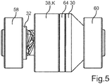
- the coupling 22 In order to be able to move the door particularly advantageously and in particular manually, the coupling 22 - how particularly well when viewed together Fig. 3 and 4th It can be seen - a driver element 30 which is, for example, at least indirectly non-rotatably connected to the threaded spindle 24.
- the coupling 22 comprises an actuating element 32, which can be driven by the drive shaft 14 by rotating the drive shaft 14 and thereby rotatable about an actuating axis of rotation 34 relative to the housing 18.
- the actuation axis of rotation 34 coincides with the shaft axis of rotation 16 and with the spindle axis of rotation 26.
- the actuation element 32 has first actuation areas 36 which, for example, run obliquely to the actuation axis of rotation 34 and / or wind helically around the actuation axis of rotation 34.
- the actuating element 32 is therefore also referred to as a screw adjuster, for example.
- the clutch 22 also has a clutch element 38, which has second operating areas 40 corresponding to the respective first operating areas 36. It can be seen from the figures that the driver element 30 and the coupling element 38 are designed as disks, so that the driver element 30 is also referred to as a driver disk and the coupling element 38 is also referred to as a clutch disk.
- the coupling element 38 is also along the actuation axis of rotation 34 relative to the driver element 30 and relative to the housing 18 between at least one in Fig. 3 shown decoupling position E and at least one for example in Fig. 4 illustrated coupling position K translationally movable and thus displaceable.
- the decoupling position E the coupling element 38 is decoupled from the driver element 30, so that no torques can be transmitted between the coupling element 38 and the driver element 30.
- the coupling element 38 is coupled to the driver element 30 in a torque-transmitting manner.
- Coupling element 38 and the driver element 30 in the coupling position K are positively connected to each other in a torque-transmitting manner, so that torques running around the actuating axis of rotation 34 can be transmitted between the coupling element 38 and the driver element 30. From a synopsis of Fig.
- the coupling element 38 which is in the coupling position K, can be driven by rotating the actuating element 32 and thereby rotatable with the actuating element 32 about the actuating axis of rotation 34 relative to the housing 18.
- the driver element 30 and, via the driver element 30, the threaded spindle 24 can be driven and thus rotatable about the spindle axis of rotation 26 or the actuating axis of rotation 34 relative to the housing 18.
- the actuation areas 36 and 40 run in respective planes which run obliquely to the actuation axis of rotation 34.
- a further displacement of the coupling element 38 from the coupling position K away from the actuating element 32 is avoided in that the coupling element 38 points away from and with the actuating element 32
- the support direction coinciding with the actuating axis of rotation 34 or running parallel to the actuating axis of rotation 34 is at least indirectly, in particular directly, supported on the driver element 30.
- the driver element 30 thus prevents further displacements of the coupling element 38 from the coupling position K away from the actuating element 32.
- the actuation areas 36 and 40 already overlap in the decoupling position E in extending around the actuation axis of rotation 34 and for example in Fig. 2 by a double arrow 42 illustrated circumferential direction.
- the actuation areas 40 of the coupling element 38 delimit a receptacle 44 into which the actuation areas 36 engage both in the decoupling position E and in the coupling position K.
- the coupling element 38 located in the coupling position K is then activated when the actuating element 32 is rotated about the actuating axis of rotation 34 relative to the housing 18 while the The coupling element 38 is in the coupling position K, rotated with the actuating element 32 and thus rotated about the actuating axis of rotation 34 relative to the housing 18.
- the driver element 30 and via this the threaded spindle 24 are also rotated about the actuating axis of rotation 34 relative to the housing 18, whereby the door is moved relative to the housing element.
- the door drive 10 has a spring element 46 designed as a mechanical spring, which is supported along the actuating axis of rotation 34 at least indirectly, in particular directly, on the coupling element 38 and, on the other hand, at least indirectly, in particular directly, on the driver element 30.
- the spring element 46 By moving the coupling element 38 from the decoupling position E into the coupling position K, the spring element 46 is tensioned, in particular compressed.
- the spring element 46 provides a spring force, at least in the coupling position K, which acts at least indirectly on the coupling element 38 along the actuation axis of rotation.
- the coupling element 38 is held in the coupling position K against the spring force. If the exertion of the torque on the actuating element 32 is ended, the spring element 46 can, for example, at least partially relax. As a result the coupling element 38 is moved back from the coupling position K into the decoupling position E, in particular pushed back, by means of the spring element 46, that is to say by means of the spring force provided by the spring element 46. Since the movement of the coupling element 38 from the coupling position K into the decoupling position E is also referred to as opening the coupling 22, the spring element 46 is also referred to as an opening spring.
- the door drive 10 is separate from the coupling element 38 and separate from the housing 18 trained brake elements 48, also referred to as brake shoes.
- the respective braking element 48 is secured against rotation about the actuating axis of rotation 34 and relative to the housing 18.
- the respective braking element 48 is, for example, designed and made as a leaf spring Fig. 2 recognizable spring 51 is coupled to the housing 18, in particular such that the respective spring 51 secures the respective braking element 48 against a rotation occurring about the actuating axis of rotation 34 and relative to the housing 18.
- the respective spring 51 preferably designed as a leaf spring, however, exhibits one Fig. 3 recognizable and in particular designed as a spring force force F ready, which acts obliquely or preferably perpendicular to the actuation axis of rotation 34 and in the direction of the coupling element 38.
- the respective brake element 48 is kept in, in particular direct, contact with the coupling element 38.
- the coupling element 38 is braked with respect to its rotation relative to the housing 18 against the housing 18 by means of the respective braking element 48.
- the respective braking element 48 has at least one or more conical first surfaces 50.
- the coupling element 38 has at least one or more conical second surfaces 52.
- the respective first conical surface 50 lies directly against the respective second conical surface 52, so that the respective conical surfaces 50 and 52 touch one another directly.
- the conical surfaces 50 and 52 thus act as friction cones, by means of which, on the one hand, an advantageous braking of the coupling element 38 with respect to it relative to the actuating axis of rotation 34 the housing 18 following rotation can be realized.
- the friction cones excessive braking of the coupling element 38 with regard to its displacement running along the actuating axis of rotation 34 and relative to the housing 18 can be avoided.
- the braking elements 48 or the braking of the coupling element 38 provided by the braking elements 48 excessively opposes the displacement of the coupling element 38 between the decoupling position E and the coupling position K.
- the respective brake element 48 can be displaced along the actuating axis of rotation 34 with the coupling element 38 relative to the housing 18.
- the respective brake element 48 slides on the respective spring 51 and along the respective spring 51.
- the conical surfaces 52 of the coupling element 38 delimit a recess 54 which is designed as a groove, in particular as an annular groove, for example, which extends completely circumferentially and thus without interruption in the circumferential direction of the coupling element 38.
- the braking elements 48 engage in the recess 54 in such a way that the conical surfaces 50 are arranged in the recess 54 and thus engage in the recess 54.
- a motor flange 56 can also be seen in the figures, via which, for example, the drive motor 12 and, if applicable, the gear 20 are connected to the housing 18 and, in particular, are supported or fixed in a rotationally fixed manner on the housing 18.
- bearings 58 and 60 spaced apart from one another and designed as roller bearings, for example, are provided in the axial direction of the drive motor 12, the coupling element 38 and the driver element 30 being arranged between the bearings 58 and 60 in the axial direction.
- the coupling 22 is mounted on the housing 18, in particular in the radial direction and in the axial direction.
- the bearings 58 and 60 limit one or the movement of the coupling element 38 along the actuation axis of rotation 34 in the direction of the actuation element 32 or the drive motor 12 and in the opposite direction and thus in the direction of the driver element 30 or the threaded spindle 24.
- the door drive 10 also has a further bearing 62 functioning as a spindle bearing, by means of which, for example, the threaded spindle 24 is mounted on the housing 18 in the radial direction and / or in the axial direction. While the in Figs. 1 to 4 The first embodiment shown, the driver element 30 and the coupling element 38 cooperate in the coupling position K in a form-fitting manner and are thus coupled to one another in a form-fitting manner in a torque-transmitting manner Fig.
- a clutch friction lining 64 is provided, for example, which is held, for example, on the driver element 30 or on the clutch element 38.
- the actuating element 32 is rotated about the actuating axis of rotation 34 in a first direction of rotation by means of the drive motor 12. This is brought about, for example, by a corresponding operation by a human user, that is to say a person, that is, initiated or caused.
- the actuating element 32 is automatically activated by means of the drive motor 12, i.e.
Abstract
Die Erfindung betrifft einen Türantrieb (10) für eine Tür, mit einem Antriebsmotor (12), mit einer von dem Antriebsmotor (12) antreibbaren und dadurch drehbaren Antriebswelle (14), mit einer Kupplung (22), und mit einer Gewindespindel (24), welche über die Kupplung (22) von der Antriebswelle (14) antreibbar und dadurch drehbar ist, wobei die Kupplung (22) aufweist:- ein Mitnehmerelement (30),- ein Betätigungselement (32), welches durch Drehen der Antriebswelle (14) von der Antriebswelle (14) antreibbar und dadurch um eine Betätigungsdrehachse (34) drehbar ist und wenigstens einen ersten Betätigungsbereich (36) aufweist, und- ein Kupplungselement (38), welches wenigstens einen mit dem ersten Betätigungsbereich (36) korrespondierenden zweiten Betätigungsbereich (40) aufweist und entlang der Betätigungsdrehachse (34) relativ zu dem Mitnehmerelement (30) zwischen wenigstens einer Entkoppelstellung (E), in welcher das Kupplungselement (38) von dem Mitnehmerelement (30) entkoppelt ist, und wenigstens einer Koppelstellung (K) translatorisch bewegbar ist, in welcher das Kupplungselement (38) mit dem Mitnehmerelement (30) gekoppelt ist, wobei mittels der Betätigungsbereiche (38, 40) eine durch Drehen der Antriebswelle (12) bewirkbare Relativdrehung zwischen dem Betätigungselement (32) und dem Kupplungselement (38) in eine entlang der Betätigungsdrehachse (34), relativ zu dem Mitnehmerelement (30), relativ zu dem Betätigungselement (32) und in Richtung des Mitnehmerelements (30) erfolgende, translatorische Bewegung des Kupplungselements (38) aus der Entkoppelstellung (E) in die Koppelstellung (K) umwandelbar ist.The invention relates to a door drive (10) for a door, with a drive motor (12), with a drive shaft (14) that can be driven and thus rotated by the drive motor (12), with a coupling (22), and with a threaded spindle (24) which can be driven and rotated by the drive shaft (14) via the coupling (22), the coupling (22) having: - a driver element (30), - an actuating element (32) which, by rotating the drive shaft (14) can be driven by the drive shaft (14) and is thereby rotatable about an actuation axis of rotation (34) and has at least one first actuation area (36), and a coupling element (38) which has at least one second actuation area (40) corresponding to the first actuation area (36) ) and along the actuating axis of rotation (34) relative to the driver element (30) between at least one decoupling position (E) in which the coupling element (38) is decoupled from the driver element (30), and w At least one coupling position (K) can be moved translationally, in which the coupling element (38) is coupled to the driver element (30), whereby by means of the actuation areas (38, 40) a relative rotation between the actuation element (32) which can be brought about by rotating the drive shaft (12) ) and the coupling element (38) in a translational movement of the coupling element (38) taking place along the actuating axis of rotation (34), relative to the driver element (30), relative to the actuating element (32) and in the direction of the driver element (30) Decoupling position (E) can be converted into the coupling position (K).
Description
Die Erfindung betrifft einen Türantrieb gemäß dem Oberbegriff von Patentanspruch 1, ein Verfahren zum Betreiben eines solchen Türantriebs gemäß dem Oberbegriff von Patentanspruch 13 und eine Vorrichtung mit wenigstens einem solchen Türantrieb.The invention relates to a door drive according to the preamble of patent claim 1, a method for operating such a door drive according to the preamble of patent claim 13 and a device with at least one such door drive.
Die
Aufgabe der vorliegenden Erfindung ist es, einen Türantrieb für eine Tür, insbesondere ein Verfahren zum Betreiben eines solchen Türantriebs sowie eine Vorrichtung zu schaffen, sodass die Tür auf besonders vorteilhafte Weise bewegt werden kann.The object of the present invention is to create a door drive for a door, in particular a method for operating such a door drive and a device so that the door can be moved in a particularly advantageous manner.
Diese Aufgabe wird erfindungsgemäß durch einen Türantrieb mit den Merkmalen des Patentanspruchs 1, durch ein Verfahren mit den Merkmalen des Patentanspruchs 13 sowie durch eine Vorrichtung mit den Merkmalen des Patentanspruchs 15 gelöst. Vorteilhafte Ausgestaltungen mit zweckmäßigen Weiterbildungen der Erfindung sind in den übrigen Ansprüchen angegeben.This object is achieved according to the invention by a door drive with the features of claim 1, by a method with the features of claim 13 and by a device with the features of claim 15. Advantageous refinements with expedient developments of the invention are specified in the remaining claims.
Ein erster Aspekt der Erfindung betrifft einen Türantrieb für eine Tür, insbesondere eines Möbelstücks oder eines, insbesondere elektrischen oder elektronischen, Geräts. Das Gerät ist vorzugsweise ein Kühl- und/oder Gefriergerät. Dies bedeutet, dass das Gerät beziehungsweise das Möbelstück in seinem vollständig hergestellten Zustand beispielsweise ein auch als Korpus bezeichnetes Gehäuseelement und die zuvor genannte Tür aufweist, welche, insbesondere über wenigstens ein Scharnier, bewegbar, insbesondere verschwenkbar, an dem Gehäuseelement gehalten und somit relativ zu dem Gehäuseelement verschwenkbar ist, während die Tür, insbesondere über das Scharnier, mit dem Gehäuseelement verbunden ist. Der Türantrieb wird dabei genutzt beziehungsweise nutzbar, um die Tür relativ zu dem Gehäuseelement zu bewegen, insbesondere zu verschwenken. Insbesondere kann beispielsweise die Tür mittels des Türantriebs geöffnet und/oder geschlossen werden. Das Gerät und das Möbelstück werden zusammenfassend auch als Vorrichtungen bezeichnet beziehungsweise sind jeweilige Vorrichtungen. Der Türantrieb weist einen Antriebsmotor auf, welcher vorzugsweise als ein Elektromotor ausgebildet und somit elektrisch beziehungsweise mittels elektrischer Energie beziehungsweise elektrischem Strom betreibbar ist. Der Türantrieb weist außerdem eine von dem Antriebsmotor antreibbare und dadurch, insbesondere um eine Wellendrehachse, drehbare Antriebswelle auf. Der Antriebsmotor weist beispielsweise einen Stator und einen von dem Stator antreibbaren und dadurch um eine Motordrehachse relativ zu dem Stator drehbaren Rotor auf, wobei die Welle beispielsweise von dem Rotor antreibbar ist. Beispielsweise ist die Welle Bestandteil des Rotors oder drehfest mit dem Rotor verbunden. Beispielsweise ist die Welle koaxial zu dem Rotor angeordnet, sodass die Motordrehachse und die Wellendrehachse zusammenfallen.A first aspect of the invention relates to a door drive for a door, in particular a piece of furniture or an, in particular electrical or electronic, device. The device is preferably a refrigerator and / or freezer. This means that the device or the piece of furniture is in its completely manufactured state For example, a housing element, also referred to as a body, and the aforementioned door, which, in particular via at least one hinge, can be moved, in particular pivoted, is held on the housing element and is thus pivotable relative to the housing element, while the door, in particular via the hinge, with is connected to the housing element. The door drive is used or can be used to move the door relative to the housing element, in particular to pivot it. In particular, for example, the door can be opened and / or closed by means of the door drive. The device and the piece of furniture are collectively referred to as devices or are respective devices. The door drive has a drive motor, which is preferably designed as an electric motor and can thus be operated electrically or by means of electrical energy or electrical current. The door drive also has a drive shaft that can be driven by the drive motor and thereby, in particular, rotatable about a shaft axis of rotation. The drive motor has, for example, a stator and a rotor that can be driven by the stator and thus rotatable about a motor axis of rotation relative to the stator, the shaft being driven, for example, by the rotor. For example, the shaft is part of the rotor or is connected to the rotor in a rotationally fixed manner. For example, the shaft is arranged coaxially to the rotor so that the motor axis of rotation and the shaft axis of rotation coincide.
Der Türantrieb weist außerdem eine Kupplung und eine Gewindespindel auf, welche über die Kupplung von der Antriebswelle antreibbar und dadurch, insbesondere um eine Spindeldrehachse, drehbar ist. Vorzugsweise ist die einfach auch als Spindel bezeichnete Gewindespindel koaxial zu der Welle angeordnet, sodass die Spindeldrehachse mit der Wellendrehachse zusammenfällt. Alternativ oder zusätzlich ist die Spindel vorzugsweise koaxial zu dem Antriebsmotor beziehungsweise zu dem Rotor angeordnet, sodass beispielsweise die Spindeldrehachse mit der Motordrehachse zusammenfällt.The door drive also has a coupling and a threaded spindle, which can be driven by the drive shaft via the coupling and thus rotatable, in particular about a spindle axis of rotation. The threaded spindle, also referred to simply as a spindle, is preferably arranged coaxially to the shaft, so that the spindle axis of rotation coincides with the shaft axis of rotation. Alternatively or additionally, the spindle is preferably arranged coaxially with the drive motor or with the rotor, so that, for example, the spindle axis of rotation coincides with the motor axis of rotation.
Die Antriebswelle, die Gewindespindel sowie gegebenenfalls der Rotor sind beispielsweise relativ zu einem Gehäuse des Türantriebs drehbar. Das Gehäuse des Türantriebs kann das Gehäuseelement der Vorrichtung sein, oder das Gehäuse ist ein separat von dem Gehäuseelement ausgebildetes und zusätzlich dazu vorgesehenes Gehäuse, welches beispielsweise zumindest mittelbar, insbesondere direkt, an dem Gehäuseelement befestigt, insbesondere festgelegt, sein kann. Die Gewindespindel weist beispielsweise ein erstes Gewinde, insbesondere in Form eines Außengewindes, auf. Dabei ist beispielsweise ein Schraubelement vorgesehen, welches beispielsweise ein mit dem ersten Gewinde korrespondierendes und beispielsweise als Innengewinde ausgebildetes zweites Gewinde aufweist. Das Schraubelement ist beispielsweise eine Mutter und kann auf die Gewindespindel aufgeschraubt sein.The drive shaft, the threaded spindle and possibly the rotor can be rotated relative to a housing of the door drive, for example. The housing of the door drive can be the housing element of the device, or the housing is formed separately from the housing element and provided in addition thereto Housing which, for example, can be fastened, in particular fixed, at least indirectly, in particular directly, to the housing element. The threaded spindle has, for example, a first thread, in particular in the form of an external thread. In this case, a screw element is provided, for example, which has, for example, a second thread that corresponds to the first thread and is designed, for example, as an internal thread. The screw element is, for example, a nut and can be screwed onto the threaded spindle.
Die Tür ist dabei über die Gewindespindel antreibbar und dadurch relativ zu dem Gehäuseelement bewegbar. Wird beispielsweise die Gewindespindel, insbesondere mittels des Antriebsmotors über die Kupplung, relativ zu dem Schraubelement gedreht, so wandeln das erste Gewinde und das zweite Gewinde die Relativdrehung zwischen der Gewindespindel und dem Schraubelement in eine translatorische Bewegung des Schraubelements um, dessen translatorische Bewegung entlang der Gewindespindel und dabei insbesondere entlang der Spindeldrehachse und relativ zu dem Gehäuse erfolgt. Hierzu ist beispielsweise das Schraubelement gegen eine um die Spindeldrehachse und relativ zu dem Gehäuse erfolgende Drehung gesichert oder eine solche Drehung des Schraubelements um die Spindeldrehachse relativ zu dem Gehäuse ist zumindest begrenzt, sodass dann, wenn die Gewindespindel um die Spindeldrehachse gedreht wird, das Schraubelement nicht mit der Gewindespindel mitgedreht wird, sondern eine Relativdrehung zwischen der Gewindespindel und dem Schraubelement erfolgt. In der Folge wird das Schraubelement entlang der Gewindespindel und insbesondere relativ zu dem Gehäuse verschoben, wodurch beispielsweise die Tür relativ zu dem Gehäuseelement bewegbar ist. Somit kann beispielsweise die Tür über das Schraubelement von der Gewindespindel angetrieben und relativ zu dem Gehäuseelement bewegt, insbesondere verschwenkt, werden.The door can be driven via the threaded spindle and can thereby be moved relative to the housing element. If, for example, the threaded spindle is rotated relative to the screw element, in particular by means of the drive motor via the coupling, the first thread and the second thread convert the relative rotation between the threaded spindle and the screw element into a translational movement of the screw element, its translational movement along the threaded spindle and takes place in particular along the spindle axis of rotation and relative to the housing. For this purpose, for example, the screw element is secured against rotation about the spindle axis of rotation and relative to the housing, or such a rotation of the screw element about the spindle axis of rotation relative to the housing is at least limited, so that when the threaded spindle is rotated about the spindle axis of rotation, the screw element does not is rotated with the threaded spindle, but there is a relative rotation between the threaded spindle and the screw element. As a result, the screw element is displaced along the threaded spindle and in particular relative to the housing, as a result of which, for example, the door can be moved relative to the housing element. Thus, for example, the door can be driven by the threaded spindle via the screw element and moved, in particular pivoted, relative to the housing element.
Um nun die Tür beziehungsweise das als Übertragungselement fungierende Schraubelement auf besonders vorteilhafte und bedarfsgerechte Weise mit dem Antriebsmotor koppeln und von dem Antriebsmotor entkoppeln und somit die Tür auf besonders vorteilhafte Weise bewegen zu können, ist es erfindungsgemäß vorgesehen, dass die Kupplung ein beispielsweise als Mitnehmerscheibe ausgebildetes Mitnehmerelement aufweist. Die Kupplung weist außerdem ein Betätigungselement auf, welches durch Drehen der Antriebswelle von der Antriebswelle antreibbar und dadurch um eine Betätigungsdrehachse, insbesondere relativ zu dem Gehäuse, drehbar ist. Vorzugsweise ist das Betätigungselement koaxial zu der Antriebswelle angeordnet, sodass die Betätigungsdrehachse mit der Wellendrehachse zusammenfällt. Das Betätigungselement weist dabei wenigstens einen ersten Betätigungsbereich auf.In order to be able to couple the door or the screw element functioning as a transmission element in a particularly advantageous and needs-based manner with the drive motor and decouple it from the drive motor and thus move the door in a particularly advantageous manner, it is provided according to the invention that the coupling is designed as a drive plate, for example Has driver element. The clutch also has an actuating element which can be driven by the drive shaft by rotating the drive shaft and thereby is rotatable about an actuating axis of rotation, in particular relative to the housing. The actuating element is preferably arranged coaxially to the drive shaft, so that the actuating axis of rotation coincides with the axis of rotation of the shaft. The actuation element has at least one first actuation area.
Die Kupplung umfasst außerdem ein Kupplungselement, welches beispielsweise als Kupplungsscheibe ausgebildet sein kann. Das Kupplungselement weist wenigstens einen mit dem ersten Betätigungsbereich korrespondierenden zweiten Betätigungsbereich auf und ist entlang der Betätigungsdrehachse relativ zu dem Mitnehmerelement und insbesondere relativ zu dem Gehäuse zwischen wenigstens einer Entkoppelstellung und wenigstens einer Koppelstellung translatorisch bewegbar, das heißt verschiebbar. In der Entkoppelstellung ist das Kupplungselement von dem Mitnehmerelement entkoppelt, sodass in der Entkoppelstellung keine Drehmomente zwischen dem Kupplungselement und dem Mitnehmerelement übertragen werden können. Beispielsweise ist das Kupplungselement in der Entkoppelstellung, insbesondere vollständig, von dem Mitnehmerelement beabstandet, insbesondere zumindest entlang der Betätigungsdrehachse. In der Koppelstellung ist das Kupplungselement mit dem Mitnehmerelement, insbesondere drehmomentübertragend, gekoppelt, sodass in der Koppelstellung Drehmomente zwischen dem Kupplungselement und dem Mitnehmerelement übertragbar sind. Befindet sich somit beispielsweise das Kupplungselement in der Koppelstellung, und wird das Kupplungselement beispielsweise in der Koppelstellung von der Antriebswelle angetrieben und dadurch beispielsweise um die Betätigungsdrehachse gedreht, so nimmt das Kupplungselement das Mitnehmerelement mit, sodass dann das Mitnehmerelement auch, insbesondere um die Betätigungsdrehachse, insbesondere relativ zu dem Gehäuse gedreht wird.The clutch also includes a clutch element, which can be designed as a clutch disc, for example. The coupling element has at least one second actuation area corresponding to the first actuation area and is translationally movable, i.e. displaceable, along the actuation axis of rotation relative to the driver element and in particular relative to the housing between at least one decoupling position and at least one coupling position. In the decoupling position, the coupling element is decoupled from the driver element, so that in the decoupling position no torques can be transmitted between the coupling element and the driver element. For example, in the decoupling position, the coupling element is at a distance, in particular completely, from the driver element, in particular at least along the actuation axis of rotation. In the coupling position, the coupling element is coupled to the driver element, in particular in a torque-transmitting manner, so that in the coupling position torques can be transmitted between the coupling element and the driver element. Thus, for example, the coupling element is in the coupling position and the coupling element is driven by the drive shaft in the coupling position, for example, and thereby rotated about the actuating axis of rotation, for example, the coupling element takes the driver element with it, so that the driver element then also, in particular about the actuating axis of rotation, in particular is rotated relative to the housing.
Mittels der Betätigungsbereiche ist eine durch Drehen der Antriebswelle bewirkbare oder bewirkte und beispielsweise um die Betätigungsdrehachse erfolgende Relativdrehung zwischen dem Betätigungselement und dem Kupplungselement in eine entlang der Betätigungsdrehachse, relativ zu dem Mitnehmerelement, relativ zu dem Betätigungselement und vorzugsweise relativ zu dem Gehäuse und in Richtung des Mitnehmerelements erfolgende, translatorische Bewegung des Kupplungselements aus der Entkoppelstellung in die Koppelstellung umwandelbar. Mit anderen Worten, wird das Betätigungselement beispielsweise von der Antriebswelle angetrieben und hierdurch um die Betätigungsdrehachse relativ zu dem Gehäuse und insbesondere relativ zu dem Kupplungselement gedreht, während sich das Kupplungselement noch in der Entkoppelstellung befindet, so wird diese Relativdrehung zwischen dem Kupplungselement und dem Betätigungselement mittels der Betätigungsbereiche in eine solche Bewegung des Kupplungselements umgewandelt, welche sich im Rahmen der zuvor genannten Bewegung entlang der Betätigungsdrehachse relativ zu dem Betätigungselement, relativ zu dem Mitnehmerelement und relativ zu dem Gehäuse entlang der Betätigungsdrehachse verschiebt und dabei auf das Mitnehmerelement zu verschiebt, derart, dass sich das Kupplungselement aus der Entkoppelstellung in die Koppelstellung bewegt beziehungsweise verschiebt und in der Folge drehmomentübertragend mit dem Mitnehmerelement gekoppelt wird beziehungsweise ist. Wird dann, das heißt nach Erreichen der Koppelstellung durch das Kupplungselement, das Betätigungselement beispielsweise weiter um die Betätigungsdrehachse relativ zu dem Gehäuse gedreht, so wird hierdurch das Kupplungselement, insbesondere um die Betätigungsdrehachse, relativ zu dem Gehäuse gedreht. Da sich dabei das Kupplungselement in der Koppelstellung befindet, nimmt das Kupplungselement das Mitnehmerelement mit, wodurch das Mitnehmerelement von dem Kupplungselement, insbesondere um die Betätigungsdrehachse, relativ zu dem Gehäuse gedreht wird. Das Mitnehmerelement wiederum nimmt zumindest mittelbar, insbesondere direkt, die Gewindespindel mit, sodass die Gewindespindel um die Spindeldrehachse relativ zu dem Gehäuse gedreht wird. Hierzu ist beispielsweise das Mitnehmerelement drehmomentübertragend mit der Gewindespindel verbunden, insbesondere drehfest mit der Gewindespindel verbunden.By means of the actuating areas, a relative rotation between the actuating element and the coupling element, which can be brought about or brought about by rotating the drive shaft and takes place, for example, about the actuating axis of rotation, in a direction along the actuating axis of rotation, relative to the driver element, relative to the actuating element and preferably relative to the housing and in the direction of the Driving element taking place, translational movement of the coupling element from the decoupling position into the coupling position convertible. In other words, the actuating element is driven, for example, by the drive shaft and thereby to the actuating axis of rotation is rotated relative to the housing and in particular relative to the coupling element while the coupling element is still in the decoupling position, this relative rotation between the coupling element and the actuating element is converted by means of the actuation areas into such a movement of the coupling element, which is within the scope of the the aforementioned movement along the actuating axis of rotation relative to the actuating element, relative to the driver element and relative to the housing along the actuating axis of rotation and thereby shifts towards the driver element, such that the coupling element moves or shifts from the decoupling position into the coupling position and in the Sequence is or is coupled to transmit torque with the driver element. If then, that is, after the coupling element has reached the coupling position, the actuating element is rotated further about the actuating axis of rotation relative to the housing, the coupling element is thereby rotated relative to the housing, in particular around the actuating axis of rotation. Since the coupling element is in the coupling position, the coupling element takes the driver element with it, whereby the driver element is rotated by the coupling element, in particular about the actuating axis of rotation, relative to the housing. The driver element in turn entrains the threaded spindle at least indirectly, in particular directly, so that the threaded spindle is rotated about the spindle axis of rotation relative to the housing. For this purpose, for example, the driver element is connected to the threaded spindle in a torque-transmitting manner, in particular connected to the threaded spindle in a rotationally fixed manner.
In der Koppelstellung ist ein Kraft- beziehungsweise Drehmomentenübertragungspfad zwischen der Gewindespindel, insbesondere der Tür, und dem Antriebsmotor, insbesondere über die Kupplung, geschlossen, sodass beispielsweise Kräfte beziehungsweise Drehmomente zwischen der Gewindespindel beziehungsweise der Tür und dem Antriebsmotor über den Kraft- beziehungsweise Drehmomentenübertragungspfad übertragen werden können. In der Entkoppelstellung jedoch ist der Kraft- beziehungsweise Drehmomentenübertragungspfad, insbesondere durch die Kupplung, unterbrochen, sodass in der Entkoppelstellung keine Kräfte beziehungsweise Drehmomente zwischen der Gewindespindel beziehungsweise der Tür und dem Antriebsmotor übertragen werden können. In der Folge ist es beispielsweise möglich, dass die Tür in dem entkoppelten Zustand von einer Person manuell relativ zu dem Gehäuse bewegt, insbesondere verschwenkt, wird, ohne dass hierbei der Antriebsmotor beziehungsweise dessen Rotor von der Tür angetrieben wird. Wird beispielsweise die Tür von einer Person relativ zu dem Gehäuseelement manuell bewegt, während sich das Kupplungselement in der Entkoppelstellung befindet, so wird dann beispielsweise das Schraubelement relativ zu dem Gehäuse translatorisch bewegt, wodurch beispielsweise die Gewindespindel um die Spindeldrehachse relativ zu dem Gehäuse gedreht wird. Da sich dabei jedoch das Kupplungselement in der Entkoppelstellung befindet, werden die Antriebswelle und der Rotor nicht angetrieben und somit nicht relativ zu dem Gehäuse gedreht. In der Folge kann die Person die Tür auf besonders einfache Weise manuell bewegen.In the coupling position, a force or torque transmission path between the threaded spindle, in particular the door, and the drive motor, in particular via the coupling, is closed so that, for example, forces or torques between the threaded spindle or the door and the drive motor are transmitted via the force or torque transmission path can. In the decoupling position, however, the force or torque transmission path is interrupted, in particular by the coupling, so that in the decoupling position no forces or torques can be transmitted between the threaded spindle or the door and the drive motor. In the following it is for example possible that the door in the decoupled state is moved manually by a person relative to the housing, in particular pivoted, without the drive motor or its rotor being driven by the door. If, for example, the door is moved manually by a person relative to the housing element while the coupling element is in the decoupling position, the screw element is then, for example, moved translationally relative to the housing, whereby, for example, the threaded spindle is rotated about the spindle axis of rotation relative to the housing. However, since the coupling element is in the decoupling position, the drive shaft and the rotor are not driven and therefore not rotated relative to the housing. As a result, the person can move the door manually in a particularly simple manner.
Da es erfindungsgemäß vorgesehen ist, mittels der Betätigungsbereiche eine Relativdrehung zwischen dem Betätigungselement und dem Kupplungselement in die zuvor beschriebene Bewegung des Kupplungselements aus der Entkoppelstellung in die Koppelstellung umzuwandeln, und da die Relativdrehung zwischen dem Betätigungselement und dem Kupplungselement mittels des Antriebsmotors bewirkt wird beziehungsweise bewirkbar ist, ist es erfindungsgemäß vorgesehen, ein und denselben Antriebsmotor, insbesondere ein und denselben Rotor, sowohl zum Drehen der Gewindespindel und somit zum Bewegen der Tür als auch zum Bewegen des Kupplungselements aus der Entkoppelstellung in die Koppelstellung zu verwenden. In der Folge kann ein zusätzlich zu dem Antriebsmotor vorgesehener, von dem Antriebsmotor unterschiedlicher Aktor zum Bewegen des Kupplungselements aus der Entkoppelstellung in die Koppelstellung vermieden werden, sodass die Teileanzahl und somit die Kosten, der Bauraumbedarf und das Gewicht des Türantriebs gering gehalten werden kann. Somit ist es vorzugsweise vorgesehen, dass der erfindungsgemäße Türantrieb frei von einem zusätzlich zu dem Antriebsmotor vorgesehenen und zum Bewegen des Kupplungselements aus der Entkoppelstellung in die Koppelstellung ausgebildeten Aktor ist.Since it is provided according to the invention, by means of the actuation areas, to convert a relative rotation between the actuation element and the coupling element into the previously described movement of the coupling element from the decoupling position to the coupling position, and since the relative rotation between the actuation element and the coupling element is or can be brought about by means of the drive motor According to the invention, one and the same drive motor, in particular one and the same rotor, is used both for rotating the threaded spindle and thus for moving the door and for moving the coupling element from the decoupling position into the coupling position. As a result, an actuator that is provided in addition to the drive motor and is different from the drive motor for moving the coupling element from the decoupling position into the coupling position can be avoided, so that the number of parts and thus the costs, the space requirement and the weight of the door drive can be kept low. Thus it is preferably provided that the door drive according to the invention is free of an actuator which is provided in addition to the drive motor and designed to move the coupling element from the decoupling position into the coupling position.
In vorteilhafter Ausgestaltung der Erfindung ist das sich in der Koppelstellung befindende Kupplungselement durch Drehen des Betätigungselements antreibbar und dadurch mit dem Betätigungselement mitdrehbar, wobei durch Drehen des sich in der Koppelstellung befindenden Kupplungselements das Mitnehmerelement und über das Mitnehmerelement die Gewindespindel von dem Mitnehmerelement antreibbar und dadurch drehbar sind. Das sich in der Koppelstellung befindende Kupplungselement wird beispielsweise dadurch von dem Betätigungselement angetrieben und, insbesondere um die Betätigungsdrehachse relativ zu dem Gehäuse, gedreht, dass das sich in der Koppelstellung befindende Kupplungselement gegen eine ausgehend von der Koppelstellung weitere, entlang der Betätigungsdrehachse und relativ zu dem Gehäuse erfolgende und von dem Betätigungselement wegweisende Verschiebung gesichert ist. Mit anderen Worten, die Betätigungsbereiche bewirken sozusagen, dass bei einer Relativdrehung zwischen dem Betätigungselement und dem Kupplungselement das sich zunächst in der Entkoppelstellung befindende Kupplungselement sozusagen dem Betätigungselement beziehungsweise dessen Drehung ausweicht und sich hierfür entlang der Betätigungsdrehachse von dem Betätigungselement weg verschiebt und auf das Mitnehmerelement zu verschiebt, wobei dieses Verschieben des Kupplungselements von dem Betätigungselement weg und auf das Mitnehmerelement zu solange zugelassen ist beziehungsweise erfolgt, bis das Kupplungselement die Koppelstellung erreicht. In der Koppelstellung ist das Kupplungselement, insbesondere mittels des Mitnehmerelements, gegen eine weitere, entlang der Betätigungsdrehachse erfolgende Verschiebung von dem Betätigungselement weg gesichert, sodass durch weiteres Drehen des Betätigungselements das Kupplungselement mittels des Betätigungselements, insbesondere um die Betätigungsdrehachse relativ zu dem Gehäuse, gedreht wird. In der Folge nimmt das Kupplungselement das Mitnehmerelement mit, wodurch das Mitnehmerelement und in der Folge die Gewindespindel relativ zu dem Gehäuse gedreht werden.In an advantageous embodiment of the invention, the coupling element located in the coupling position can be driven by rotating the actuating element and thereby rotates with the actuating element, whereby by rotating the coupling element located in the coupling position the driver element and via the Driver element, the threaded spindle can be driven and thereby rotated by the driver element. The coupling element in the coupling position is, for example, driven by the actuating element and rotated, in particular about the actuating axis of rotation relative to the housing, that the coupling element in the coupling position is against a further, starting from the coupling position, along the actuating axis of rotation and relative to the Housing taking place and pointing away from the actuating element displacement is secured. In other words, the actuation areas have the effect, so to speak, that in the event of a relative rotation between the actuation element and the coupling element, the coupling element, which is initially in the decoupling position, evades the actuation element or its rotation, and for this purpose moves away from the actuation element along the actuation axis of rotation and towards the driver element shifts, this shifting of the coupling element away from the actuating element and towards the driver element being permitted or taking place until the coupling element reaches the coupling position. In the coupling position, the coupling element, in particular by means of the driver element, is secured against further displacement away from the actuating element along the actuating axis of rotation, so that by further turning the actuating element the coupling element is rotated by means of the actuating element, in particular about the actuating axis of rotation relative to the housing . As a result, the coupling element takes the driver element with it, whereby the driver element and consequently the threaded spindle are rotated relative to the housing.
Als besonders vorteilhaft hat es sich dabei gezeigt, wenn die Betätigungsbereiche in einer jeweiligen Ebene verlaufen, welche schräg zur Betätigungsdrehachse verläuft. Hierdurch wird beispielsweise ein um die Drehachse verlaufendes Drehmoment, mittels welchem beispielsweise das Betätigungselement relativ zu dem sich zunächst in der Entkoppelstellung befindenden Kupplungselement gedreht wird, beziehungsweise eine das Drehmoment bewirkende Kraft derart aufgeteilt oder zerlegt, dass aus dem Drehmoment beziehungsweise aus der Kraft eine Kraftkomponente resultiert, deren Wirkrichtung parallel zu der Betätigungsdrehachse verläuft oder mit der Betätigungsdrehachse zusammenfällt und insbesondere von dem Betätigungselement weg und in Richtung des Mitnehmerelements weist. Durch diese Kraftkomponente wird schließlich die translatorische Bewegung des Kupplungselements entlang der Betätigungsdrehachse aus der Entkoppelstellung in die Koppelstellung bewirkt. In der Koppelstellung ist beispielsweise das Kupplungselement in eine beispielsweise parallel zur Betätigungsdrehachse verlaufende und von dem Betätigungselement zu dem Mitnehmerelement weisende Abstützrichtung zumindest mittelbar, insbesondere direkt, an dem Mitnehmerelement abgestützt und dadurch gegen eine weitere, in die Abstützrichtung erfolgende Verschiebung von dem Betätigungselement weg gesichert.It has been shown to be particularly advantageous if the actuation areas run in a respective plane which runs obliquely to the actuation axis of rotation. As a result, for example, a torque running around the axis of rotation, by means of which, for example, the actuating element is rotated relative to the coupling element initially in the decoupling position, or a force causing the torque is divided or broken down in such a way that a force component results from the torque or the force whose direction of action runs parallel to the actuation axis of rotation or coincides with the actuation axis of rotation and in particular points away from the actuation element and in the direction of the driver element. This force component becomes finally causes the translational movement of the coupling element along the actuating axis of rotation from the decoupling position into the coupling position. In the coupling position, for example, the coupling element is supported on the driver element at least indirectly, in particular directly, in a support direction running parallel to the actuating axis of rotation and pointing from the actuating element to the driver element, and is thereby secured against further displacement away from the actuating element in the support direction.
Beispielsweise gleiten die Betätigungsbereiche bei der Relativdrehung zwischen dem Betätigungselement und dem Kupplungselement und bei der dadurch bewirkten, translatorischen Bewegung des Kupplungselements aus der Entkoppelstellung in die Koppelstellung aneinander, insbesondere direkt, ab. Insbesondere bewirken die Betätigungsbereiche, dass der Relativdrehung zwischen dem Betätigungselement und dem Kupplungselement eine Verschiebung des Kupplungselements aus der Entkoppelstellung in die Koppelstellung überlagert wird, sodass derselbe Antriebsmotor, insbesondere derselbe Rotor des Antriebsmotors, genutzt werden kann, um sowohl das Kupplungselement aus der Entkoppelstellung in die Koppelstellung zu bewegen als auch die Gewindespindel zu drehen und in der Folge die Tür zu bewegen.For example, during the relative rotation between the actuation element and the coupling element and during the translational movement of the coupling element caused thereby, the actuation areas slide from the decoupling position into the coupling position on one another, in particular directly. In particular, the actuation areas have the effect that the relative rotation between the actuation element and the coupling element is superimposed on a displacement of the coupling element from the decoupling position into the coupling position, so that the same drive motor, in particular the same rotor of the drive motor, can be used to move the coupling element from the decoupling position into the To move the coupling position as well as to turn the threaded spindle and then to move the door.
Eine weitere Ausführungsform zeichnet sich dadurch aus, dass sich die Betätigungsbereiche in der Entkoppelstellung in um die Betätigungsdrehachse verlaufender Umfangsrichtung gegenseitig überlappen. Hierdurch muss das Betätigungselement nicht erst gesondert verschoben werden, um durch Drehen des Betätigungselements relativ zu dem Kupplungselement das Verschieben des Kupplungselements aus der Entkoppelstellung in die Koppelstellung zu bewegen, sondern das Betätigungselement kann mittels des Rotors einfach nur gedreht werden, um das Kupplungselement aus der Entkoppelstellung in die Koppelstellung zu bewegen. Auf diese Weise kann das Kupplungselement aus der Entkoppelstellung in die Koppelstellung translatorisch bewegt werden, ohne das Betätigungselement relativ zu dem Gehäuse zu verschieben. Somit können zusätzliche Aktoren vermieden werden, sodass die Teileanzahl und somit das Gewicht, die Kosten und der Bauraumbedarf des Türantriebs besonders gering gehalten werden können.Another embodiment is characterized in that the actuation areas in the decoupling position mutually overlap in the circumferential direction running around the actuation axis of rotation. As a result, the actuating element does not first have to be shifted separately in order to move the coupling element from the decoupling position into the coupling position by rotating the actuating element relative to the coupling element, but the actuating element can simply be rotated by means of the rotor in order to move the coupling element out of the decoupling position to move into the coupling position. In this way, the coupling element can be moved translationally from the decoupling position into the coupling position without moving the actuating element relative to the housing. Additional actuators can thus be avoided, so that the number of parts and thus the weight, costs and space requirements of the door drive can be kept particularly low.
Bei einer besonders vorteilhaften Ausführungsform der Erfindung begrenzt einer der Betätigungsbereiche, insbesondere der zweite Betätigungsbereich, eine Aufnahme zumindest teilweise, in welche der andere Betätigungsbereich, insbesondere der erste Betätigungsbereich, zumindest in der Entkoppelstellung eingreift. Einerseits kann dadurch der Bauraumbedarf des Türantriebs insbesondere in axialer Richtung des Türantriebs besonders gering gehalten werden. Andererseits muss das Betätigungselement nicht erst relativ zu dem Gehäuse verschoben werden, um in Zusammenwirken mit dem Kupplungselement gebracht zu werden, sondern das Betätigungselement kann, ohne es zu verschieben, einfach um die Betätigungsdrehachse gedreht werden, um dadurch gleich das Verschieben des Kupplungselements zu bewirken.In a particularly advantageous embodiment of the invention, one of the actuation areas, in particular the second actuation area, at least partially delimits a receptacle into which the other actuation area, in particular the first actuation area, engages at least in the decoupling position. On the one hand, the space requirement of the door drive can be kept particularly low, particularly in the axial direction of the door drive. On the other hand, the actuating element does not first have to be displaced relative to the housing in order to be brought into cooperation with the coupling element, but rather the actuating element can simply be rotated around the actuating axis of rotation without moving it, thereby causing the coupling element to be displaced immediately.
Als weiterhin besonders vorteilhaft hat es sich gezeigt, wenn wenigstens ein vorzugsweise als mechanische Feder ausgebildetes Federelement vorgesehen ist, welches durch Bewegen des Kupplungselements aus der Entkoppelstellung in die Koppelstellung zu spannen ist und dadurch zumindest in der Koppelstellung eine zumindest mittelbar auf das Kupplungselement und beispielsweise entlang der Betätigungsdrehachse wirkende Federkraft bereitstellt, mittels welcher eine Bewegung des Kupplungselements aus der Koppelstellung in die Entkoppelstellung bewirkbar ist. Hierdurch kann das Kupplungselement auf besonders einfache und somit bauraum-, gewichts- und kostengünstige Weise aus der Koppelstellung zurück in die Entkoppelstellung bewegt werden.It has also been shown to be particularly advantageous if at least one spring element, preferably designed as a mechanical spring, is provided, which is to be tensioned by moving the coupling element out of the decoupling position into the coupling position and thereby, at least in the coupling position, at least indirectly onto the coupling element and, for example, along it provides spring force acting on the actuating axis of rotation, by means of which a movement of the coupling element from the coupling position into the decoupling position can be brought about. As a result, the coupling element can be moved from the coupling position back into the decoupling position in a particularly simple and thus space-saving, weight-saving and cost-effective manner.
In weiterer vorteilhafter Ausgestaltung der Erfindung ist das Kupplungselement relativ zu dem Gehäuse drehbar und relativ zu dem Gehäuse zwischen der Koppelstellung und der Entkoppelstellung translatorisch bewegbar, das heißt verschiebbar. Dabei ist wenigstens ein separat von dem Kupplungselement und vorzugsweise separat von dem Gehäuse ausgebildetes Bremselement vorgesehen, mittels welchem das Kupplungselement zumindest bezüglich dessen relativ zu dem Gehäuse erfolgender Drehung gegen das Gehäuse abbremsbar oder abgebremst ist. Hierdurch kann sichergestellt werden, dass dann, wenn sich das Kupplungselement in der Entkoppelstellung befindet und das Betätigungselement von dem Antriebsmotor angetrieben und somit um die Betätigungsdrehachse relativ zu dem Gehäuse gedreht wird, es insbesondere solange, bis sich das Kupplungselement noch nicht in der Koppelstellung befindet, zu einer Relativdrehung zwischen dem Betätigungselement und dem Kupplungselement kommt, sodass in der Folge auf die beschriebene Weise das Kupplungselement aus der Entkoppelstellung in die Koppelstellung verschoben wird. Mit anderen Worten stellt das Bremselement die gewünschte, die Bewegung des Kupplungselements aus der Entkoppelstellung in die Koppelstellung bewirkende Relativdrehung zwischen dem Betätigungselement und dem Kupplungselement sicher. Dieser Ausführungsform liegt insbesondere die Erkenntnis zugrunde, dass es beispielsweise bei Einsatz eines Getriebes, über welches die Antriebswelle von dem Antriebsmotor angetrieben wird, und insbesondere dann, wenn das Getriebe eine große Übersetzung aufweist, zu solch ungünstigen Trägheitsverhältnissen kommen kann, dass beispielsweise dann, wenn das Kupplungselement nicht mittels des Bremselements gegenüber dem Gehäuse und gegenüber einer relativ zu dem Gehäuse erfolgenden Drehung abgebremst wird, das sich in der Entkoppelstellung befindende Kupplungselement mit dem Betätigungselement mitgedreht wird, ohne dass eine Relativdrehung zwischen dem Betätigungselement und dem sich in der Entkoppelstellung befindenden Kupplungselement auftritt und somit ohne dass das sich in der Entkoppelstellung befindende Kupplungselement in die Koppelstellung verschoben wird. Insgesamt ist erkennbar, dass durch Verwendung des Bremselements auch dann eine gewünschte Relativdrehung zwischen dem Betätigungselement und dem sich in der Entkoppelstellung befindenden Kupplungselement und die daraus resultierende Verschiebung des Kupplungselements aus der Entkoppelstellung in die Koppelstellung sichergestellt werden kann, wenn ein eine hohe Übersetzung aufweisendes Getriebe zum Einsatz kommt, über welches die Antriebswelle von dem Rotor angetrieben wird.In a further advantageous embodiment of the invention, the coupling element can be rotated relative to the housing and can be moved translationally, that is to say displaceable, relative to the housing between the coupling position and the decoupling position. At least one braking element formed separately from the coupling element and preferably separately from the housing is provided, by means of which the coupling element can be braked or braked at least with respect to its rotation relative to the housing against the housing. This makes it possible to ensure that when the coupling element is in the decoupling position and the actuating element is driven by the drive motor and thus rotated about the actuating axis of rotation relative to the housing, in particular until the coupling element is not in the Coupling position is located, there is a relative rotation between the actuating element and the coupling element, so that the coupling element is subsequently displaced from the decoupling position into the coupling position in the manner described. In other words, the braking element ensures the desired relative rotation between the actuating element and the coupling element which brings about the movement of the coupling element from the decoupling position into the coupling position. This embodiment is based, in particular, on the knowledge that, for example, when using a gear via which the drive shaft is driven by the drive motor, and in particular when the gear has a large gear ratio, such unfavorable inertia conditions can occur that, for example, when the coupling element is not braked by means of the braking element with respect to the housing and with respect to a rotation taking place relative to the housing, the coupling element in the decoupling position is rotated with the actuating element without a relative rotation occurring between the actuation element and the coupling element in the decoupling position and thus without the coupling element in the decoupling position being shifted into the coupling position. Overall, it can be seen that by using the braking element, a desired relative rotation between the actuating element and the coupling element located in the decoupling position and the resulting displacement of the coupling element from the decoupling position into the coupling position can also be ensured when a gear with a high gear ratio is used for Use comes through which the drive shaft is driven by the rotor.
Um eine besonders vorteilhafte Bremswirkung zu realisieren, ist es in einer Ausgestaltung der Erfindung vorgesehen, dass zumindest eine erste Fläche des Bremselements zumindest eine zweite Fläche des Kupplungselements direkt berührt. Unter dem Merkmal, dass mittels des Bremselements das Kupplungselement zumindest bezüglich dessen relativ zu dem Gehäuse erfolgender Drehung gegen das Gehäuse abbremsbar ist, ist zu verstehen, dass das Bremselement eine relativ zu dem Gehäuse und insbesondere um die Betätigungsdrehachse erfolgende Drehung des Kupplungselements nicht vollständig vermeidet, sondern zulässt und einer solchen Relativdrehung zwischen dem Kupplungselement und dem Gehäuse lediglich entgegensteht.In order to achieve a particularly advantageous braking effect, it is provided in one embodiment of the invention that at least a first surface of the braking element directly contacts at least a second surface of the coupling element. The feature that the coupling element can be braked against the housing by means of the braking element at least with respect to its rotation relative to the housing is to be understood as meaning that the braking element does not completely avoid a rotation of the coupling element relative to the housing and in particular about the actuation axis of rotation, but allows and such Relative rotation between the coupling element and the housing only opposes.
Als besonders vorteilhaft hat es sich gezeigt, wenn sich die Flächen in einer jeweiligen, schräg zur Betätigungsdrehachse verlaufenden Ebene erstrecken. Mit anderen Worten erstreckt sich beispielsweise eine erste der Flächen in einer ersten Ebene, und die zweite Fläche erstreckt sich in einer zweiten Ebene, wobei die Ebenen schräg zur Betätigungsdrehachse verlaufen. Vorzugsweise verlaufen die Ebenen parallel zueinander. Die jeweilige Fläche ist somit beispielsweise ein Keil, ein Konus, keilförmig oder konusförmig. Mit anderen Worten ist es vorzugsweise vorgesehen, dass die Flächen konusförmig oder konussegmentförmig ausgebildet sind, sodass beispielsweise die jeweilige Fläche durch einen jeweiligen Konus, insbesondere durch einen jeweiligen Reibkonus, gebildet ist. Dabei ist das Kupplungselement gegenüber dessen relativ zu dem Gehäuse und beispielsweise um die Betätigungsdrehachse erfolgender Drehung mittels der Reibkonusse gegenüber dem Gehäuse abbremsbar. Unter dem Merkmal, dass sich die jeweilige Fläche in einer jeweiligen, schräg zu der Betätigungsdrehachse verlaufenden Ebene erstreckt, kann auch verstanden werden, dass beispielsweise dann, wenn die jeweilige Fläche konusförmig ausgebildet ist, eine die jeweilige Fläche tangierende Ebene schräg zu der Betätigungsdrehachse verläuft.It has been shown to be particularly advantageous if the surfaces extend in a respective plane running obliquely to the actuation axis of rotation. In other words, for example, a first of the surfaces extends in a first plane and the second surface extends in a second plane, the planes extending obliquely to the actuation axis of rotation. The planes preferably run parallel to one another. The respective surface is thus, for example, a wedge, a cone, wedge-shaped or conical. In other words, it is preferably provided that the surfaces are conical or conical segment-shaped so that, for example, the respective surface is formed by a respective cone, in particular by a respective friction cone. In this case, the coupling element can be braked relative to its rotation relative to the housing and, for example, about the actuating axis of rotation by means of the friction cones relative to the housing. The feature that the respective surface extends in a respective plane running obliquely to the actuating axis of rotation can also be understood to mean that, for example, when the respective surface is conical, a plane tangent to the respective surface runs obliquely to the actuating axis of rotation.
Es wurde gefunden, dass durch Abbremsen des Kupplungselements gegenüber dem Gehäuse mittels der beschriebenen Reibkonusse das Kupplungselement hinsichtlich dessen relativ zu dem Gehäuse erfolgender Drehung vorteilhaft abgebremst werden kann, um eine die Verschiebung des Kupplungselements aus der Entkoppelstellung in die Koppelstellung bewirkende Relativdrehung zwischen dem Betätigungselement und dem Kupplungselement sicherzustellen. Eine übermäßige, unerwünschte Abbremsung des Kupplungselements hinsichtlich dessen relativ zu dem Gehäuse erfolgender Verschiebung aus der Entkoppelstellung in die Koppelstellung kann jedoch durch Verwendung der Reibkonusse vermieden werden. Somit kann einerseits sichergestellt werden, dass das Kupplungselement hinreichend abgebremst wird, um eine Relativdrehung zwischen dem Betätigungselement und dem Kupplungselement sicherzustellen. Eine übermäßige Abbremsung des Kupplungselements entlang der Betätigungsdrehachse kann jedoch vermieden werden.It has been found that by braking the coupling element with respect to the housing by means of the friction cones described, the coupling element can advantageously be braked with regard to its rotation relative to the housing in order to achieve a relative rotation between the actuating element and the actuating element that causes the displacement of the coupling element from the decoupling position into the coupling position Ensure coupling element. However, excessive, undesired braking of the coupling element with regard to its displacement from the decoupling position into the coupling position relative to the housing can be avoided by using the friction cones. Thus, on the one hand, it can be ensured that the coupling element is braked sufficiently to ensure a relative rotation between the actuating element and the coupling element. However, excessive braking of the coupling element along the actuation axis of rotation can be avoided.
Vorzugsweise ist das Bremselement mit dem Kupplungselement relativ zu dem Gehäuse mitverschiebbar. Beispielsweise ist das Bremselement über eine beispielsweise als Blattfeder ausgebildete Feder, welche vorzugsweise eine mechanische Feder ist, mit dem Gehäuse gekoppelt beziehungsweise an dem Gehäuse gehalten. Mittels der Feder ist beispielsweise die Fläche des Bremselements in, insbesondere direkter, Stützanlage mit der Fläche des Kupplungselements gehalten. Beispielsweise ist das Bremselement entlang der Feder relativ zu dem Gehäuse mit dem Kupplungselement mitverschiebbar. Bei entlang der Betätigungsdrehachse und relativ zu dem Gehäuse erfolgenden Relativverschiebungen zwischen dem Kupplungselement und dem Gehäuse und somit zwischen dem Bremselement und dem Gehäuse gleitet beispielsweise das Bremselement entlang der Feder und/oder an der Feder ab. Die Feder fungiert somit beispielsweise als Führung, mittels welcher das Bremselement bei entlang der Betätigungsdrehachse und relativ zu dem Gehäuse erfolgenden Verschiebungen zu führen ist beziehungsweise geführt wird. Alternativ oder zusätzlich ist beispielsweise das Bremselement mittels der Feder gegen relativ zu dem Gehäuse und um die Betätigungsdrehachse erfolgende Drehungen gesichert.The braking element can preferably be displaced with the coupling element relative to the housing. For example, the braking element is coupled to the housing or held on the housing by means of a spring, for example designed as a leaf spring, which is preferably a mechanical spring. By means of the spring, for example, the surface of the braking element is held in, in particular, direct, supporting contact with the surface of the coupling element. For example, the braking element can be displaced along with the spring relative to the housing with the coupling element. In the case of relative displacements between the coupling element and the housing and thus between the braking element and the housing occurring along the actuation axis of rotation and relative to the housing, for example the braking element slides along the spring and / or on the spring. The spring thus functions, for example, as a guide by means of which the braking element is to be guided or is guided in the case of displacements occurring along the actuating axis of rotation and relative to the housing. Alternatively or in addition, for example, the brake element is secured against rotations occurring relative to the housing and about the actuating axis of rotation by means of the spring.
Eine weitere Ausführungsform zeichnet sich dadurch aus, dass eine der Flächen eine Ausnehmung zumindest teilweise begrenzt, in welche die andere Fläche eingreift. Dadurch kann eine besonders vorteilhafte Abbremsung des Kupplungselements sichergestellt werden.Another embodiment is characterized in that one of the surfaces at least partially delimits a recess into which the other surface engages. A particularly advantageous braking of the coupling element can thereby be ensured.
Bei einer besonders vorteilhaften Ausführungsform der Erfindung ist es vorgesehen, dass das Bremselement aus einem ersten Werkstoff, insbesondere aus einem Kunststoff und vorzugsweise aus einem faserverstärkten Kunststoff, und das Kupplungselement aus einem von dem ersten Werkstoff unterschiedlichen zweiten Werkstoff, insbesondere aus einem metallischen Werkstoff, gebildet ist. Hierdurch kann eine besonders vorteilhafte Bremsung des Kupplungselements gewährleistet werden.In a particularly advantageous embodiment of the invention, it is provided that the braking element is formed from a first material, in particular from a plastic and preferably from a fiber-reinforced plastic, and the coupling element from a second material different from the first material, in particular from a metallic material is. A particularly advantageous braking of the coupling element can hereby be ensured.
Eine weitere Ausführungsform zeichnet sich dadurch aus, dass das Kupplungselement und das Mitnehmerelement in der Koppelstellung formschlüssig und/oder kraftschlüssig zusammenwirken und dadurch, insbesondere drehmomentübertragend, miteinander gekoppelt sind. Dadurch kann sichergestellt werden, dass das Kupplungselement das Mitnehmerelement sicher mitnimmt.Another embodiment is characterized in that the coupling element and the driver element interact in the coupling position in a form-fitting and / or force-fitting manner and are thereby coupled to one another, in particular in a torque-transmitting manner. It can thereby be ensured that the coupling element securely entrains the driver element.
Ein zweiter Aspekt der Erfindung betrifft ein Verfahren zum Betreiben eines Türantriebs, insbesondere gemäß dem ersten Aspekt der Erfindung, für eine Tür. Bei dem Verfahren wird die Tür mittels des Antriebs angetrieben und dadurch relativ zu einem Gehäuseelement aus einer ersten Stellung in eine von der ersten Stellung unterschiedliche zweite Stellung bewegt. Der Türantrieb weist einen Antriebsmotor und eine Antriebswelle auf, welche beim Antreiben der Tür von dem Antriebsmotor angetrieben und dadurch gedreht wird. Der Türantrieb weist außerdem eine Kupplung und eine Gewindespindel auf, welche beim Antreiben der Tür über die Kupplung von der Antriebswelle angetrieben und dadurch gedreht wird, wodurch die Tür über die Gewindespindel, die Kupplung und die Antriebswelle von dem Motor angetrieben wird.A second aspect of the invention relates to a method for operating a door drive, in particular according to the first aspect of the invention, for a door. In the method, the door is driven by means of the drive and thereby moved relative to a housing element from a first position into a second position different from the first position. The door drive has a drive motor and a drive shaft which is driven by the drive motor when the door is driven and is rotated thereby. The door drive also has a coupling and a threaded spindle which, when the door is driven via the coupling, is driven by the drive shaft and thereby rotated, whereby the door is driven by the motor via the threaded spindle, the coupling and the drive shaft.
Um die Tür besonders vorteilhaft bewegen zu können, ist es erfindungsgemäß vorgesehen, dass die Kupplung ein Mitnehmerelement und ein Betätigungselement aufweist, welches durch das Drehen der Antriebswelle von der Antriebswelle angetrieben und dadurch um eine Betätigungsdrehachse gedreht wird und wenigstens einen ersten Betätigungsbereich aufweist. Die Kupplung weist außerdem ein Kupplungselement auf, welches wenigstens einen mit dem ersten Betätigungsbereich korrespondierenden zweiten Betätigungsbereich aufweist und entlang der Betätigungsdrehachse relativ zu dem Mitnehmerelement zwischen wenigstens einer Entkoppelstellung, in welcher das Kupplungselement von dem Mitnehmerelement entkoppelt ist, und wenigstens einer Koppelstellung translatorisch bewegbar ist, in welcher das Kupplungselement mit dem Mitnehmerelement gekoppelt ist. Mittels der Betätigungsbereiche wird eine durch Drehen der Antriebswelle bewirkte Relativdrehung zwischen dem Betätigungselement und dem Kupplungselement in eine entlang der Betätigungsdrehachse, relativ zu dem Mitnehmerelement, relativ zu dem Betätigungselement und in Richtung des Mitnehmerelements erfolgende, translatorische Bewegung des Kupplungselements aus der Entkoppelstellung in die Koppelstellung umgewandelt. Vorteile und vorteilhafte Ausgestaltungen des ersten Aspekts der Erfindung sind als Vorteile und vorteilhafte Ausgestaltungen des zweiten Aspekts der Erfindung anzusehen und umgekehrt.In order to be able to move the door particularly advantageously, it is provided according to the invention that the coupling has a driver element and an actuating element which is driven by the rotation of the drive shaft by the drive shaft and is thereby rotated about an actuating axis of rotation and has at least one first actuation area. The coupling also has a coupling element which has at least one second actuation area corresponding to the first actuation area and is translationally movable along the actuation axis of rotation relative to the driver element between at least one decoupling position in which the coupling element is decoupled from the driver element and at least one coupling position, in which the coupling element is coupled to the driver element. By means of the actuation areas, a relative rotation between the actuation element and the coupling element caused by rotating the drive shaft is converted into a translational movement of the coupling element from the decoupling position into the coupling position along the actuation axis of rotation, relative to the driver element, relative to the actuating element and in the direction of the driver element . Advantages and advantageous configurations of the first aspect of the invention are to be regarded as advantages and advantageous configurations of the second aspect of the invention and vice versa.
Um beispielsweise eine insbesondere mittels des zuvor genannten Federelements bewirkte oder bewirkbare Bewegung des Kupplungselements aus der Koppelstellung zurück in die Entkoppelstellung auf einfache und kostengünstige Weise zuzulassen, ist es in vorteilhafter Ausgestaltung der Erfindung vorgesehen, dass zum Bewegen der Tür in die zweite Stellung das Betätigungselement über die Antriebswelle mittels des Antriebsmotors in eine erste Drehrichtung, insbesondere relativ zu dem Gehäuse, gedreht wird. Nach dem Bewegen der Tür in die zweite Stellung wird das Betätigungselement über die Antriebswelle mittels des Antriebsmotors, insbesondere automatisch, derart ein Stück in eine der ersten Drehrichtung entgegengesetzte zweite Drehrichtung, insbesondere relativ zu dem Gehäuse, zurückgedreht, dass eine Bewegung der Tür aus der zweiten Stellung unterbleibt oder die Tür in eine zwischen der ersten Stellung und der zweiten Stellung und näher an der zweiten Stellung als an der ersten Stellung liegende Zwischenstellung bewegt wird. Das Zurückdrehen des Betätigungselements erfolgt somit automatisch und zumindest nahezu ohne Bewegen der Tür, sodass die Tür zumindest nahezu in der zweiten Stellung verbleibt, das Federelement jedoch das Kupplungselement aus der Kuppelstellung in die Entkoppelstellung zurückbewegen, insbesondere zurückdrücken, kann. Dadurch kann eine besonders vorteilhafte Bewegbarkeit der Tür sichergestellt werden.In order, for example, to allow a movement of the coupling element from the coupling position back into the decoupling position, which is brought about or can be brought about in particular by means of the aforementioned spring element, in a simple and inexpensive manner It is provided in an advantageous embodiment of the invention that, in order to move the door into the second position, the actuating element is rotated via the drive shaft by means of the drive motor in a first direction of rotation, in particular relative to the housing. After moving the door into the second position, the actuating element is rotated back via the drive shaft by means of the drive motor, in particular automatically, a little in a second direction of rotation opposite to the first direction of rotation, in particular relative to the housing, so that a movement of the door out of the second Position is omitted or the door is moved into an intermediate position between the first position and the second position and closer to the second position than to the first position. The actuation element is thus turned back automatically and at least almost without moving the door, so that the door remains at least almost in the second position, but the spring element can move the coupling element back from the coupling position into the decoupling position, in particular pushing it back. A particularly advantageous mobility of the door can thereby be ensured.
Ein dritter Aspekt der Erfindung betrifft eine Vorrichtung, mit einem Gehäuseelement, mit einer an dem Gehäuseelement gelenkig gehaltenen und relativ zu dem Gehäuseelement bewegbaren, insbesondere verschwenkbaren, Tür, und wenigstens einem erfindungsgemäßen Türantrieb gemäß dem ersten Aspekt der Erfindung, wobei die Tür mittels des Türantriebs antreibbar und dadurch relativ zu dem Gehäuse bewegbar ist. Vorteile und vorteilhafte Ausgestaltungen des ersten und zweiten Aspekts der Erfindung sind als Vorteile und vorteilhafte Ausgestaltungen des dritten Aspekts der Erfindung anzusehen und umgekehrt. Wie zuvor angedeutet, ist die Vorrichtung beispielsweise das zuvor genannte Gerät oder das zuvor genannte Möbelstück.A third aspect of the invention relates to a device with a housing element, with a door hingedly held on the housing element and movable, in particular pivotable, relative to the housing element, and at least one door drive according to the invention according to the first aspect of the invention, the door by means of the door drive can be driven and thereby moved relative to the housing. Advantages and advantageous configurations of the first and second aspects of the invention are to be regarded as advantages and advantageous configurations of the third aspect of the invention and vice versa. As previously indicated, the device is, for example, the aforementioned device or the aforementioned piece of furniture.
Weitere Vorteile, Merkmale und Einzelheiten der Erfindung ergeben sich aus der nachfolgenden Beschreibung eines bevorzugten Ausführungsbeispiels sowie anhand der Zeichnung. Die vorstehend in der Beschreibung genannten Merkmale und Merkmalskombinationen sowie die nachfolgend in der Figurenbeschreibung genannten und/oder in den Figuren alleine gezeigten Merkmale und Merkmalskombinationen sind nicht nur in der jeweils angegebenen Kombination, sondern auch in anderen Kombinationen oder in Alleinstellung verwendbar, ohne den Rahmen der Erfindung zu verlassen.Further advantages, features and details of the invention emerge from the following description of a preferred exemplary embodiment and with reference to the drawing. The features and combinations of features mentioned above in the description as well as the features and combinations of features mentioned below in the description of the figures and / or shown alone in the figures can be used not only in the respectively specified combination, but also in other combinations or on their own, without the scope of the Invention to leave.
Die Zeichnung zeigt in:
- Fig. 1
- eine schematische und teilweise geschnittene Seitenansicht eines erfindungsgemäßen Türantriebs gemäß einer ersten Ausführungsform für eine Tür;
- Fig. 2
- ausschnittsweise eine schematische und teilweise geschnittene Seitenansicht des Türantriebs;
- Fig. 3
- ausschnittsweise eine schematische Seitenansicht des Türantriebs;
- Fig. 4
- ausschnittsweise eine weitere schematische Seitenansicht des Türantriebs; und
- Fig. 5
- ausschnittsweise eine schematische Seitenansicht des Türantriebs gemäß einer zweiten Ausführungsform.
- Fig. 1
- a schematic and partially sectioned side view of a door drive according to the invention according to a first embodiment for a door;
- Fig. 2
- a detail of a schematic and partially sectioned side view of the door drive;
- Fig. 3
- a detail of a schematic side view of the door drive;
- Fig. 4
- a detail of a further schematic side view of the door drive; and
- Fig. 5
- a detail of a schematic side view of the door drive according to a second embodiment.
In den Fig. sind gleiche oder funktionsgleiche Elemente mit gleichen Bezugszeichen versehen.Identical or functionally identical elements are provided with the same reference symbols in the figures.
Hierzu weist der Türantrieb 10 einen vorzugsweise als Elektromotor ausgebildeten Antriebsmotor 12 und eine von dem Antriebsmotor 12 antreibbare und besonders gut aus
In vollständig hergestelltem Zustand der Vorrichtung ist beispielsweise ein Schraubelement in Form einer Spindelmutter vorgesehen, welche auch einfach als Mutter bezeichnet wird. Die Spindelmutter weist ein mit dem Gewinde 28 korrespondierendes und als Innengewinde ausgebildetes zweites Gewinde auf, wobei die Gewindemutter über die Gewinde mit der Gewindespindel 24 verschraubt ist. Die Tür ist beispielsweise zumindest mittelbar und/oder gelenkig mit der Spindelmutter gekoppelt. Außerdem ist die Spindelmutter beispielsweise gegen eine relativ zu dem Gehäuse 18 erfolgende Drehung gesichert. Wird somit die Gewindespindel 24 von dem Antriebsmotor 12 angetrieben und somit um die Spindeldrehachse 26 relativ zu dem Gehäuse 18 gedreht, so wird dadurch die Gewindespindel 24 auch relativ zu der Spindelmutter gedreht. Da die Spindelmutter gegen relativ zu dem Gehäuse 18 und um die Spindeldrehachse 26 erfolgende Drehungen gesichert ist, dreht sich die Spindelmutter nicht mit der Gewindespindel 24 mit, sondern die Spindelmutter wird, insbesondere je nach Drehrichtung der Gewindespindel 24, entlang der Spindeldrehachse 26 relativ zu dem Gehäuse 18 translatorisch bewegt, das heißt verschoben. Hierdurch wird die Tür relativ zu dem Gehäuseelement bewegt, insbesondere verschwenkt.In the completely manufactured state of the device, a screw element in the form of a spindle nut is provided, for example, which is also referred to simply as a nut. The spindle nut has a second thread which corresponds to the
Um nun die Tür besonders vorteilhaft und insbesondere manuell bewegen zu können, weist die Kupplung 22 - wie besonders gut in Zusammenschau mit
Die Kupplung 22 weist darüber hinaus ein Kupplungselement 38 auf, welches mit den jeweiligen ersten Betätigungsbereichen 36 korrespondierende zweite Betätigungsbereiche 40 aufweist. Aus den Fig. ist erkennbar, dass das Mitnehmerelement 30 und das Kupplungselement 38 als Scheiben ausgebildet sind, sodass das Mitnehmerelement 30 auch als Mitnehmerscheibe und das Kupplungselement 38 auch als Kupplungsscheibe bezeichnet wird.The clutch 22 also has a
Das Kupplungselement 38 ist außerdem entlang der Betätigungsdrehachse 34 relativ zu dem Mitnehmerelement 30 und relativ zu dem Gehäuse 18 zwischen wenigstens einer in
Dabei ist das sich in der Koppelstellung K befindende Kupplungselement 38 durch Drehen des Betätigungselements 32 antreibbar und dadurch mit dem Betätigungselement 32 um die Betätigungsdrehachse 34 relativ zu dem Gehäuse 18 mitdrehbar. Durch Drehen des sich in der Koppelstellung K befindenden Kupplungselements 38 ist das Mitnehmerelement 30 und über das Mitnehmerelement 30 die Gewindespindel 24 antreibbar und dadurch um die Spindeldrehachse 26 beziehungsweise die Betätigungsdrehachse 34 relativ zu dem Gehäuse 18 drehbar. Beispielsweise verlaufen die Betätigungsbereiche 36 und 40 in jeweiligen Ebenen, welche schräg zur Betätigungsdrehachse 34 verlaufen. Hierunter ist insbesondere zu verstehen, dass beispielsweise eine jeweilige, den jeweiligen Betätigungsbereich 36 beziehungsweise 40 tangierende Ebene schräg zu der Betätigungsdrehachse 34 verläuft. Dadurch resultiert beispielsweise aus einem Drehmoment, mittels welchem das Betätigungselement 32 um die Betätigungsdrehachse 34 relativ zu dem Gehäuse 18 gedreht wird, während sich das Kupplungselement 38 noch in der Entkoppelstellung E befindet, wenigstens eine Kraft oder Kraftkomponente, deren Wirkrichtung parallel zur Betätigungsdrehsachse 34 verläuft und in Richtung des Mitnehmerelements 30 weist. Mittels dieser Kraftkomponente wird das sich zunächst in der Entkoppelstellung E befindende Kupplungselement 38 aus der Entkoppelstellung E in die Koppelstellung K bewegt. Eine weitere Verschiebung des Kupplungselements 38 aus der Koppelstellung K von dem Betätigungselement 32 weg wird dadurch vermieden, dass das Kupplungselement 38 in einer von dem Betätigungselement 32 weg weisende und mit der Betätigungsdrehsachse 34 zusammenfallende oder parallel zu der Betätigungsdrehsachse 34 verlaufende Abstützrichtung zumindest mittelbar, insbesondere direkt, an dem Mitnehmerelement 30 abgestützt ist. Das Mitnehmerelement 30 verhindert somit weitere Verschiebungen des Kupplungselements 38 aus der Koppelstellung K von dem Betätigungselement 32 weg.The
Die Betätigungsbereiche 36 und 40 überlappen sich bereits in der Entkoppelstellung E in um die Betätigungsdrehachse 34 verlaufender und beispielsweise in
Besonders gut aus
Um die Relativdrehung zwischen dem sich zunächst in der Entkoppelstellung E befindenden Kupplungselement 38 und dem Betätigungselement 32 und die daraus resultierende Verschiebung des Kupplungselements 38 aus der Entkoppelstellung E in die Koppelstellung K sicherzustellen, weist der Türantrieb 10 separat von dem Kupplungselement 38 und separat von dem Gehäuse 18 ausgebildete, auch als Bremsbacken bezeichnete Bremselemente 48 auf. Das jeweilige Bremselement 48 ist gegen eine um die Betätigungsdrehachse 34 und relativ zu dem Gehäuse 18 erfolgende Drehung gesichert. Hierzu ist beispielsweise das jeweilige Bremselement 48 über eine beispielsweise als Blattfeder ausgebildete und aus
Das jeweilige Bremselement 48 weist wenigstens eine oder aber mehrere, konische erste Flächen 50 auf. Das Kupplungselement 38 weist wenigstens eine oder aber mehrere, konische zweite Flächen 52 auf. Die jeweilige erste konische Fläche 50 liegt dabei direkt an der jeweiligen zweiten konischen Fläche 52 an, sodass sich die jeweiligen konischen Flächen 50 und 52 direkt gegenseitig berühren. Die konischen Flächen 50 und 52 wirken somit als Reibkonusse, mittels welchen einerseits eine vorteilhafte Abbremsung des Kupplungselements 38 hinsichtlich dessen um die Betätigungsdrehachse 34 relativ zu dem Gehäuse 18 erfolgender Drehung realisierbar ist. Andererseits kann durch die Verwendung der Reibkonusse ein übermäßiges Abbremsen des Kupplungselements 38 hinsichtlich dessen entlang der Betätigungsdrehachse 34 verlaufender und relativ zu dem Gehäuse 18 erfolgender Verschiebung vermieden werden. Somit kann einerseits eine gewünschte Relativdrehung zwischen dem Betätigungselement 32 und dem Kupplungselement 38 gewährleistet werden. Andererseits kann vermieden werden, dass die Bremselemente 48 beziehungsweise die durch die Bremselemente 48 bereitgestellte Bremsung des Kupplungselements 38 der Verschiebung des Kupplungselements 38 zwischen der Entkoppelstellung E und der Koppelstellung K übermäßig entgegensteht. Dabei ist das jeweilige Bremselement 48 entlang der Betätigungsdrehachse 34 mit dem Kupplungselement 38 relativ zu dem Gehäuse 18 mitverschiebbar. Hierbei gleitet beispielsweise das jeweilige Bremselement 48 an der jeweiligen Feder 51 ab und entlang der jeweiligen Feder 51.The
Aus
Aus
Um beispielsweise die Tür aus der ersten Stellung in die zweite Stellung zu bewegen, wird beispielsweise das Betätigungselement 32 um die Betätigungsdrehachse 34 in eine erste Drehrichtung mittels des Antriebsmotors 12 gedreht. Dies wird beispielsweise durch eine entsprechende Bedienung eines menschlichen Nutzers, das heißt einer Person, bewirkt, das heißt initiiert oder veranlasst. Um beispielsweise sicherzustellen, dass die Öffnungsfeder das Kupplungselement 38 aus der Koppelstellung K in die Entkoppelstellung E zurückschieben, insbesondere zurückdrücken, kann, nachdem die Tür in die zweite Stellung bewegt wurde, wird beispielsweise das Betätigungselement 32 mittels des Antriebsmotors 12 automatisch, das heißt ohne eine durch eine Person bewirkte Bedienung des Türantriebs 10 das Betätigungselement 32 in eine der ersten Drehrichtung entgegengesetzte zweite Drehrichtung um die Betätigungsdrehachse 34 relativ zu dem Gehäuse 18 gedreht und somit zurückgedreht, nachdem die Tür in die zweite Stellung bewegt wurde und ohne dass die Tür, insbesondere übermäßig, aus der zweiten Stellung herausbewegt wird. In der Folge kann das Kupplungselement 38 sicher in die Entkoppelstellung E bewegt werden, woraufhin beispielsweise die Person die Tür manuell verschwenken kann, ohne dabei den Antriebsmotor 12 anzutreiben. In der Folge kann eine besonders vorteilhafte Bewegung beziehungsweise Betätigung der Tür gewährleistet werden.To move the door from the first position into the second position, for example, the
Claims (15)
dadurch gekennzeichnet, dass
die Kupplung (22) aufweist:
characterized in that
the coupling (22) has:
dadurch gekennzeichnet, dass
das sich in der Koppelstellung (K) befindende Kupplungselement (38) durch Drehen des Betätigungselements (32) antreibbar und dadurch mit dem Betätigungselement (32) mitdrehbar ist, wobei durch Drehen des sich in der Koppstellung (K) befindenden Kupplungselements (38) das Mitnehmerelement (30) und über das Mitnehmerelement (30) die Gewindespindel (24) von dem Kupplungselement (38) antreibbar und dadurch drehbar sind.Door drive (10) according to claim 1,
characterized in that
the coupling element (38) in the coupling position (K) Rotation of the actuating element (32) can be driven and thereby co-rotated with the actuating element (32), whereby by rotating the coupling element (38) in the coupling position (K), the driver element (30) and the threaded spindle (24) via the driver element (30) ) can be driven by the coupling element (38) and thereby rotatable.
dadurch gekennzeichnet, dass
die Betätigungsbereiche (38, 40) in einer jeweiligen Ebene verlaufen, welche schräg zur Betätigungsdrehachse (34) verläuft.Door drive (10) according to claim 1 or 2,
characterized in that
the actuation areas (38, 40) run in a respective plane which runs obliquely to the actuation axis of rotation (34).
dadurch gekennzeichnet, dass
sich die Betätigungsbereiche (38, 40) in der Entkoppelstellung (E) in um die Betätigungsdrehachse (34) verlaufender Umfangsrichtung (42) gegenseitig überlappen.Door drive (10) according to one of the preceding claims,
characterized in that
the actuation areas (38, 40) in the decoupling position (E) overlap in the circumferential direction (42) running around the actuation axis of rotation (34).
dadurch gekennzeichnet, dass
einer der Betätigungsbereiche (38, 40) eine Aufnahme (44) zumindest teilweise begrenzt, in welche der andere Betätigungsbereich (40, 38) zumindest in der Entkoppelstellung (E) eingreift.Door drive (10) according to one of the preceding claims,
characterized in that
one of the actuation areas (38, 40) at least partially delimits a receptacle (44) in which the other actuation area (40, 38) engages at least in the decoupling position (E).
gekennzeichnet durch
wenigstens ein Federelement (46), welches durch Bewegen des Kupplungselements (38) aus der Entkoppelstellung (E) in die Koppelstellung (K) zu spannen ist und dadurch zumindest in der Koppelstellung (K) eine zumindest mittelbar auf das Kupplungselement (38) wirkende Federkraft bereitstellt, mittels welcher eine Bewegung des Kupplungselements (38) aus der Koppelstellung (K) in die Entkoppelstellung (E) bewirkbar ist.Door drive (10) according to one of the preceding claims,
marked by
at least one spring element (46), which is to be tensioned by moving the coupling element (38) from the decoupling position (E) into the coupling position (K) and thereby at least in the coupling position (K) a spring force acting at least indirectly on the coupling element (38) provides, by means of which a movement of the coupling element (38) from the coupling position (K) into the decoupling position (E) can be brought about.
dadurch gekennzeichnet, dass
ein Gehäuse (18) vorgesehen ist, wobei das Kupplungselement (38) relativ zu dem Gehäuse (18) drehbar und zwischen der Koppelstellung (K) und der Entkoppelstellung (E) translatorisch bewegbar ist, wobei wenigstens ein separat von dem Kupplungselement (38) ausgebildetes Bremselement (48) vorgesehen ist, mittels welchem das Kupplungselement (38) zumindest bezüglich dessen relativ zu dem Gehäuse (18) erfolgender Drehung gegen das Gehäuse (18) abbremsbar ist.Door drive (10) according to one of the preceding claims,
characterized in that
a housing (18) is provided, the coupling element (38) being rotatable relative to the housing (18) and translationally movable between the coupling position (K) and the decoupling position (E), at least one being formed separately from the coupling element (38) Brake element (48) is provided, by means of which the coupling element (38) can be braked against the housing (18) at least with respect to its rotation relative to the housing (18).
dadurch gekennzeichnet, dass
zumindest eine erste Fläche (50) des Bremselements (38) zumindest eine zweite Fläche (52) des Kupplungselements (38) direkt berührt.Door drive (10) according to claim 7,
characterized in that
at least a first surface (50) of the braking element (38) directly contacts at least a second surface (52) of the coupling element (38).
dadurch gekennzeichnet, dass
die Flächen (50, 52) konisch ausgebildet sind und/oder sich in einer jeweiligen, schräg zur Betätigungsdrehachse (34) verlaufenden Ebene erstrecken.Door drive (10) according to claim 8,
characterized in that
the surfaces (50, 52) are conical and / or extend in a respective plane running obliquely to the actuation axis of rotation (34).
dadurch gekennzeichnet, dass
eine der Flächen (50, 52) eine Ausnehmung (54) zumindest teilweise begrenzt, in welche die andere Fläche (52, 50) eingreift.Door drive (10) according to claim 8 or 9,
characterized in that
one of the surfaces (50, 52) at least partially delimits a recess (54) into which the other surface (52, 50) engages.
dadurch gekennzeichnet, dass
das Bremselement (38)aus einem ersten Werkstoff, insbesondere aus einem Kunststoff, vorzugsweise aus einem faserverstärkten Kunststoff, und das Kupplungselement (38) aus einem von dem ersten Werkstoff unterschiedlichen zweiten Werkstoff, insbesondere aus einem metallischen Werkstoff, gebildet ist.Door drive (10) according to one of Claims 7 to 10,
characterized in that
the braking element (38) is made of a first material, in particular a plastic, preferably a fiber-reinforced plastic, and the coupling element (38) is made of a second material that is different from the first material, in particular a metallic material.
dadurch gekennzeichnet, dass
das Kupplungselement (38) und das Mitnehmerelement (30) in der Koppelstellung (K) formschlüssig und/oder kraftschlüssig zusammenwirken und dadurch miteinander gekoppelt sind.Door drive (10) according to one of the preceding claims,
characterized in that
the coupling element (38) and the driver element (30) in the Coupling position (K) interact positively and / or non-positively and are thereby coupled to one another.
die Kupplung (22) aufweist:
the coupling (22) has:
dadurch gekennzeichnet, dass
zum Bewegen der Tür in die zweite Stellung das Betätigungselement (32) über die Antriebswelle (14) mittels des Antriebsmotors (12) in eine erste Drehrichtung gedreht wird, wobei nach dem Bewegen der Tür in die zweite Stellung das Betätigungselement (32) über die Antriebswelle (14) mittels des Antriebsmotors (12), insbesondere automatisch, derart ein Stück in eine der ersten Drehrichtung entgegengesetzte zweite Drehrichtung zurückgedreht wird, dass eine Bewegung der Tür aus der zweiten Stellung unterbleibt oder die Tür in eine zwischen der ersten Stellung und der zweiten Stellung und näher an der zweiten Stellung als an der ersten Stellung liegende Zwischenstellung bewegt wird.Method according to claim 13,
characterized in that
to move the door into the second position, the actuating element (32) is rotated via the drive shaft (14) by means of the drive motor (12) in a first direction of rotation, after moving the door into the second position the actuating element (32) via the drive shaft (14) by means of the drive motor (12), in particular automatically, is rotated back a little in a second direction of rotation opposite to the first direction of rotation, so that the door does not move out of the second position or the door into one between the first position and the second position and is moved closer to the second position than the intermediate position located to the first position.
Priority Applications (4)
| Application Number | Priority Date | Filing Date | Title |
|---|---|---|---|
| EP19425052.8A EP3767061B1 (en) | 2019-07-15 | 2019-07-15 | Door drive for a door, especially of a piece of furniture or a device, method for operating such a door drive and device comprising at least one such door drive |
| ES19425052T ES2918386T3 (en) | 2019-07-15 | 2019-07-15 | Door drive for a door, in particular of a piece of furniture or an appliance, method for operating such a door drive and device with at least one such door drive |
| US16/920,944 US11499358B2 (en) | 2019-07-15 | 2020-07-06 | Door drive for a door, in particular of a piece of furniture or an appliance, method for operating such a door drive as well as device with at least one such door drive |
| CN202010681035.1A CN112227869B (en) | 2019-07-15 | 2020-07-15 | Door drive for a door of a piece of furniture or an appliance, method for operating a door drive, and device having at least one door drive |
Applications Claiming Priority (1)
| Application Number | Priority Date | Filing Date | Title |
|---|---|---|---|
| EP19425052.8A EP3767061B1 (en) | 2019-07-15 | 2019-07-15 | Door drive for a door, especially of a piece of furniture or a device, method for operating such a door drive and device comprising at least one such door drive |
Publications (2)
| Publication Number | Publication Date |
|---|---|
| EP3767061A1 true EP3767061A1 (en) | 2021-01-20 |
| EP3767061B1 EP3767061B1 (en) | 2022-05-04 |
Family
ID=67847667
Family Applications (1)
| Application Number | Title | Priority Date | Filing Date |
|---|---|---|---|
| EP19425052.8A Active EP3767061B1 (en) | 2019-07-15 | 2019-07-15 | Door drive for a door, especially of a piece of furniture or a device, method for operating such a door drive and device comprising at least one such door drive |
Country Status (4)
| Country | Link |
|---|---|
| US (1) | US11499358B2 (en) |
| EP (1) | EP3767061B1 (en) |
| CN (1) | CN112227869B (en) |
| ES (1) | ES2918386T3 (en) |
Cited By (1)
| Publication number | Priority date | Publication date | Assignee | Title |
|---|---|---|---|---|
| EP4047164A1 (en) * | 2021-02-18 | 2022-08-24 | Apparatebau Gronbach S.R.L. | Drive for an apparatus, arrangement and domestic appliance |
Families Citing this family (2)
| Publication number | Priority date | Publication date | Assignee | Title |
|---|---|---|---|---|
| DE202021102062U1 (en) * | 2021-04-16 | 2021-04-23 | Edscha Engineering Gmbh | Activatable drive device |
| US20230049706A1 (en) * | 2021-08-11 | 2023-02-16 | Hi-Lex Controls, Inc. | Power actuator for automotive passenger door |
Citations (3)
| Publication number | Priority date | Publication date | Assignee | Title |
|---|---|---|---|---|
| EP2148035A2 (en) | 2008-07-24 | 2010-01-27 | SUSPA Holding GmbH | Drive device for refrigerator doors |
| DE102016113353A1 (en) * | 2016-07-20 | 2018-01-25 | Brose Fahrzeugteile Gmbh & Co. Kg, Bamberg | Drive arrangement of a closure element arrangement |
| US20190040670A1 (en) * | 2017-08-04 | 2019-02-07 | Faringosi Hinges S.R.L. | Motorized hinge |
Family Cites Families (7)
| Publication number | Priority date | Publication date | Assignee | Title |
|---|---|---|---|---|
| US3690427A (en) * | 1970-09-10 | 1972-09-12 | Int Harvester Co | Positive shifted jaw clutch |
| JPS6095228A (en) * | 1983-10-29 | 1985-05-28 | Matsushita Electric Ind Co Ltd | Plastic brake shoe |
| DE102007020826B4 (en) * | 2007-05-02 | 2019-01-03 | Stabilus Gmbh | driving means |
| CN106714981A (en) * | 2014-09-23 | 2017-05-24 | Sika技术股份公司 | Application device for materials |
| US10648231B2 (en) * | 2016-01-14 | 2020-05-12 | Hunter Douglas, Inc. | Methods and apparatus for controlling architectural opening coverings in more than one mode |
| DE102016116876A1 (en) | 2016-09-08 | 2018-03-08 | Brose Fahrzeugteile Gmbh & Co. Kg, Bamberg | drive arrangement |
| CN106761141B (en) | 2017-03-07 | 2019-03-26 | 上海胜华波汽车电器有限公司 | Electronic strut with overload protection function |
-
2019
- 2019-07-15 EP EP19425052.8A patent/EP3767061B1/en active Active
- 2019-07-15 ES ES19425052T patent/ES2918386T3/en active Active
-
2020
- 2020-07-06 US US16/920,944 patent/US11499358B2/en active Active
- 2020-07-15 CN CN202010681035.1A patent/CN112227869B/en active Active
Patent Citations (3)
| Publication number | Priority date | Publication date | Assignee | Title |
|---|---|---|---|---|
| EP2148035A2 (en) | 2008-07-24 | 2010-01-27 | SUSPA Holding GmbH | Drive device for refrigerator doors |
| DE102016113353A1 (en) * | 2016-07-20 | 2018-01-25 | Brose Fahrzeugteile Gmbh & Co. Kg, Bamberg | Drive arrangement of a closure element arrangement |
| US20190040670A1 (en) * | 2017-08-04 | 2019-02-07 | Faringosi Hinges S.R.L. | Motorized hinge |
Cited By (1)
| Publication number | Priority date | Publication date | Assignee | Title |
|---|---|---|---|---|
| EP4047164A1 (en) * | 2021-02-18 | 2022-08-24 | Apparatebau Gronbach S.R.L. | Drive for an apparatus, arrangement and domestic appliance |
Also Published As
| Publication number | Publication date |
|---|---|
| US11499358B2 (en) | 2022-11-15 |
| CN112227869A (en) | 2021-01-15 |
| CN112227869B (en) | 2022-04-19 |
| ES2918386T3 (en) | 2022-07-15 |
| EP3767061B1 (en) | 2022-05-04 |
| US20210017801A1 (en) | 2021-01-21 |
Similar Documents
| Publication | Publication Date | Title |
|---|---|---|
| EP3516251B1 (en) | Actuation system and clutch device for a motor vehicle | |
| EP3767061B1 (en) | Door drive for a door, especially of a piece of furniture or a device, method for operating such a door drive and device comprising at least one such door drive | |
| EP1056960A1 (en) | Electromagnetically actuated disk brake | |
| DE102006045163A1 (en) | Double clutch for a dual-clutch transmission | |
| EP2098743A1 (en) | Adjustment mechanism for inserting and extracting a separation coupling with rotating curve segment | |
| WO2003093695A1 (en) | Hydrodynamic brake | |
| EP3508676B1 (en) | Hinge for a domestic appliance | |
| DE102005014633A1 (en) | Clutch actuating method for motor vehicle, involves converting rotary motion of servo drive into translatory motion of shifter to actuate clutch, where kinetic energy for actuating clutch is obtained partly from drive train apart from motor | |
| EP1143160A2 (en) | Double clutch assembly | |
| DE102009036872B4 (en) | door unit | |
| DE102019130202B4 (en) | Multi-plate clutch device, hybrid module and drive arrangement | |
| DE102012006097A1 (en) | Clamping device for a lever-operated disc brake | |
| EP0716242B1 (en) | Electric motor drive of a friction coupling | |
| EP1586784A1 (en) | Procedure and clutch actuator to actuate at least one clutch in a vehicle transmission | |
| DE102019110891A1 (en) | Hybrid module and drive train for a motor vehicle | |
| EP4130515B1 (en) | Driving device for an adjustable vehicle door | |
| DE102008028265B4 (en) | Adjustment device for a disc brake | |
| DE102019100969B4 (en) | Dry double clutch for an electric axle as well as electric axle with the dry double clutch | |
| DE10257865A1 (en) | Device for actuating vehicle brakes | |
| DE102021203008A1 (en) | Actuating device for an electromechanically actuatable motor vehicle brake | |
| DE10029708A1 (en) | Vehicle brake device has pot-shaped piston containing ramp unit and connected to drive shaft connected to electric motor to move ramp unit to move brake disc with two linings inside casing | |
| DE10238117B4 (en) | Indenter arrangement for generating an engagement force for a friction clutch | |
| DE102006010248A1 (en) | Electric motor with linkage system is used as an actuator for the clutch mechanism in an automobile | |
| EP0635653A2 (en) | Device for transmitting/absorbing rotational torque | |
| WO2021089218A1 (en) | Cone friction clutch having an actuator and a lever for disengaging the clutch |
Legal Events
| Date | Code | Title | Description |
|---|---|---|---|
| PUAI | Public reference made under article 153(3) epc to a published international application that has entered the european phase |
Free format text: ORIGINAL CODE: 0009012 |
|
| STAA | Information on the status of an ep patent application or granted ep patent |
Free format text: STATUS: THE APPLICATION HAS BEEN PUBLISHED |
|
| AK | Designated contracting states |
Kind code of ref document: A1 Designated state(s): AL AT BE BG CH CY CZ DE DK EE ES FI FR GB GR HR HU IE IS IT LI LT LU LV MC MK MT NL NO PL PT RO RS SE SI SK SM TR |
|
| AX | Request for extension of the european patent |
Extension state: BA ME |
|
| STAA | Information on the status of an ep patent application or granted ep patent |
Free format text: STATUS: REQUEST FOR EXAMINATION WAS MADE |
|
| 17P | Request for examination filed |
Effective date: 20210709 |
|
| RBV | Designated contracting states (corrected) |
Designated state(s): AL AT BE BG CH CY CZ DE DK EE ES FI FR GB GR HR HU IE IS IT LI LT LU LV MC MK MT NL NO PL PT RO RS SE SI SK SM TR |
|
| GRAP | Despatch of communication of intention to grant a patent |
Free format text: ORIGINAL CODE: EPIDOSNIGR1 |
|
| STAA | Information on the status of an ep patent application or granted ep patent |
Free format text: STATUS: GRANT OF PATENT IS INTENDED |
|
| RIC1 | Information provided on ipc code assigned before grant |
Ipc: F16D 11/04 20060101ALI20211123BHEP Ipc: E05F 15/622 20150101AFI20211123BHEP |
|
| INTG | Intention to grant announced |
Effective date: 20211221 |
|
| GRAS | Grant fee paid |
Free format text: ORIGINAL CODE: EPIDOSNIGR3 |
|
| GRAA | (expected) grant |
Free format text: ORIGINAL CODE: 0009210 |
|
| STAA | Information on the status of an ep patent application or granted ep patent |
Free format text: STATUS: THE PATENT HAS BEEN GRANTED |
|
| AK | Designated contracting states |
Kind code of ref document: B1 Designated state(s): AL AT BE BG CH CY CZ DE DK EE ES FI FR GB GR HR HU IE IS IT LI LT LU LV MC MK MT NL NO PL PT RO RS SE SI SK SM TR |
|
| REG | Reference to a national code |
Ref country code: GB Ref legal event code: FG4D Free format text: NOT ENGLISH |
|
| REG | Reference to a national code |
Ref country code: CH Ref legal event code: EP |
|
| REG | Reference to a national code |
Ref country code: AT Ref legal event code: REF Ref document number: 1489213 Country of ref document: AT Kind code of ref document: T Effective date: 20220515 |
|
| REG | Reference to a national code |
Ref country code: DE Ref legal event code: R096 Ref document number: 502019004259 Country of ref document: DE |
|
| REG | Reference to a national code |
Ref country code: IE Ref legal event code: FG4D Free format text: LANGUAGE OF EP DOCUMENT: GERMAN |
|
| REG | Reference to a national code |
Ref country code: ES Ref legal event code: FG2A Ref document number: 2918386 Country of ref document: ES Kind code of ref document: T3 Effective date: 20220715 |
|
| REG | Reference to a national code |
Ref country code: LT Ref legal event code: MG9D |
|
| REG | Reference to a national code |
Ref country code: NL Ref legal event code: MP Effective date: 20220504 |
|
| PG25 | Lapsed in a contracting state [announced via postgrant information from national office to epo] |
Ref country code: SE Free format text: LAPSE BECAUSE OF FAILURE TO SUBMIT A TRANSLATION OF THE DESCRIPTION OR TO PAY THE FEE WITHIN THE PRESCRIBED TIME-LIMIT Effective date: 20220504 Ref country code: PT Free format text: LAPSE BECAUSE OF FAILURE TO SUBMIT A TRANSLATION OF THE DESCRIPTION OR TO PAY THE FEE WITHIN THE PRESCRIBED TIME-LIMIT Effective date: 20220905 Ref country code: NO Free format text: LAPSE BECAUSE OF FAILURE TO SUBMIT A TRANSLATION OF THE DESCRIPTION OR TO PAY THE FEE WITHIN THE PRESCRIBED TIME-LIMIT Effective date: 20220804 Ref country code: NL Free format text: LAPSE BECAUSE OF FAILURE TO SUBMIT A TRANSLATION OF THE DESCRIPTION OR TO PAY THE FEE WITHIN THE PRESCRIBED TIME-LIMIT Effective date: 20220504 Ref country code: LT Free format text: LAPSE BECAUSE OF FAILURE TO SUBMIT A TRANSLATION OF THE DESCRIPTION OR TO PAY THE FEE WITHIN THE PRESCRIBED TIME-LIMIT Effective date: 20220504 Ref country code: HR Free format text: LAPSE BECAUSE OF FAILURE TO SUBMIT A TRANSLATION OF THE DESCRIPTION OR TO PAY THE FEE WITHIN THE PRESCRIBED TIME-LIMIT Effective date: 20220504 Ref country code: GR Free format text: LAPSE BECAUSE OF FAILURE TO SUBMIT A TRANSLATION OF THE DESCRIPTION OR TO PAY THE FEE WITHIN THE PRESCRIBED TIME-LIMIT Effective date: 20220805 Ref country code: FI Free format text: LAPSE BECAUSE OF FAILURE TO SUBMIT A TRANSLATION OF THE DESCRIPTION OR TO PAY THE FEE WITHIN THE PRESCRIBED TIME-LIMIT Effective date: 20220504 Ref country code: BG Free format text: LAPSE BECAUSE OF FAILURE TO SUBMIT A TRANSLATION OF THE DESCRIPTION OR TO PAY THE FEE WITHIN THE PRESCRIBED TIME-LIMIT Effective date: 20220804 |
|
| PG25 | Lapsed in a contracting state [announced via postgrant information from national office to epo] |
Ref country code: RS Free format text: LAPSE BECAUSE OF FAILURE TO SUBMIT A TRANSLATION OF THE DESCRIPTION OR TO PAY THE FEE WITHIN THE PRESCRIBED TIME-LIMIT Effective date: 20220504 Ref country code: PL Free format text: LAPSE BECAUSE OF FAILURE TO SUBMIT A TRANSLATION OF THE DESCRIPTION OR TO PAY THE FEE WITHIN THE PRESCRIBED TIME-LIMIT Effective date: 20220504 Ref country code: LV Free format text: LAPSE BECAUSE OF FAILURE TO SUBMIT A TRANSLATION OF THE DESCRIPTION OR TO PAY THE FEE WITHIN THE PRESCRIBED TIME-LIMIT Effective date: 20220504 Ref country code: IS Free format text: LAPSE BECAUSE OF FAILURE TO SUBMIT A TRANSLATION OF THE DESCRIPTION OR TO PAY THE FEE WITHIN THE PRESCRIBED TIME-LIMIT Effective date: 20220904 |
|
| PG25 | Lapsed in a contracting state [announced via postgrant information from national office to epo] |
Ref country code: SM Free format text: LAPSE BECAUSE OF FAILURE TO SUBMIT A TRANSLATION OF THE DESCRIPTION OR TO PAY THE FEE WITHIN THE PRESCRIBED TIME-LIMIT Effective date: 20220504 Ref country code: SK Free format text: LAPSE BECAUSE OF FAILURE TO SUBMIT A TRANSLATION OF THE DESCRIPTION OR TO PAY THE FEE WITHIN THE PRESCRIBED TIME-LIMIT Effective date: 20220504 Ref country code: RO Free format text: LAPSE BECAUSE OF FAILURE TO SUBMIT A TRANSLATION OF THE DESCRIPTION OR TO PAY THE FEE WITHIN THE PRESCRIBED TIME-LIMIT Effective date: 20220504 Ref country code: EE Free format text: LAPSE BECAUSE OF FAILURE TO SUBMIT A TRANSLATION OF THE DESCRIPTION OR TO PAY THE FEE WITHIN THE PRESCRIBED TIME-LIMIT Effective date: 20220504 Ref country code: DK Free format text: LAPSE BECAUSE OF FAILURE TO SUBMIT A TRANSLATION OF THE DESCRIPTION OR TO PAY THE FEE WITHIN THE PRESCRIBED TIME-LIMIT Effective date: 20220504 Ref country code: CZ Free format text: LAPSE BECAUSE OF FAILURE TO SUBMIT A TRANSLATION OF THE DESCRIPTION OR TO PAY THE FEE WITHIN THE PRESCRIBED TIME-LIMIT Effective date: 20220504 |
|
| REG | Reference to a national code |
Ref country code: DE Ref legal event code: R097 Ref document number: 502019004259 Country of ref document: DE |
|
| PG25 | Lapsed in a contracting state [announced via postgrant information from national office to epo] |
Ref country code: MC Free format text: LAPSE BECAUSE OF FAILURE TO SUBMIT A TRANSLATION OF THE DESCRIPTION OR TO PAY THE FEE WITHIN THE PRESCRIBED TIME-LIMIT Effective date: 20220504 |
|
| REG | Reference to a national code |
Ref country code: CH Ref legal event code: PL |
|
| PLBE | No opposition filed within time limit |
Free format text: ORIGINAL CODE: 0009261 |
|
| STAA | Information on the status of an ep patent application or granted ep patent |
Free format text: STATUS: NO OPPOSITION FILED WITHIN TIME LIMIT |
|
| REG | Reference to a national code |
Ref country code: BE Ref legal event code: MM Effective date: 20220731 |
|
| PG25 | Lapsed in a contracting state [announced via postgrant information from national office to epo] |
Ref country code: AL Free format text: LAPSE BECAUSE OF FAILURE TO SUBMIT A TRANSLATION OF THE DESCRIPTION OR TO PAY THE FEE WITHIN THE PRESCRIBED TIME-LIMIT Effective date: 20220504 |
|
| 26N | No opposition filed |
Effective date: 20230207 |
|
| PG25 | Lapsed in a contracting state [announced via postgrant information from national office to epo] |
Ref country code: LU Free format text: LAPSE BECAUSE OF NON-PAYMENT OF DUE FEES Effective date: 20220715 Ref country code: LI Free format text: LAPSE BECAUSE OF NON-PAYMENT OF DUE FEES Effective date: 20220731 Ref country code: FR Free format text: LAPSE BECAUSE OF NON-PAYMENT OF DUE FEES Effective date: 20220731 Ref country code: CH Free format text: LAPSE BECAUSE OF NON-PAYMENT OF DUE FEES Effective date: 20220731 |
|
| PG25 | Lapsed in a contracting state [announced via postgrant information from national office to epo] |
Ref country code: BE Free format text: LAPSE BECAUSE OF NON-PAYMENT OF DUE FEES Effective date: 20220731 |
|
| P01 | Opt-out of the competence of the unified patent court (upc) registered |
Effective date: 20230526 |
|
| PG25 | Lapsed in a contracting state [announced via postgrant information from national office to epo] |
Ref country code: IE Free format text: LAPSE BECAUSE OF NON-PAYMENT OF DUE FEES Effective date: 20220715 |
|
| PGFP | Annual fee paid to national office [announced via postgrant information from national office to epo] |
Ref country code: TR Payment date: 20230713 Year of fee payment: 5 Ref country code: IT Payment date: 20230731 Year of fee payment: 5 Ref country code: ES Payment date: 20230821 Year of fee payment: 5 |
|
| PGFP | Annual fee paid to national office [announced via postgrant information from national office to epo] |
Ref country code: SI Payment date: 20230710 Year of fee payment: 5 Ref country code: DE Payment date: 20230728 Year of fee payment: 5 |
|
| GBPC | Gb: european patent ceased through non-payment of renewal fee |
Effective date: 20230715 |
|
| PG25 | Lapsed in a contracting state [announced via postgrant information from national office to epo] |
Ref country code: MK Free format text: LAPSE BECAUSE OF FAILURE TO SUBMIT A TRANSLATION OF THE DESCRIPTION OR TO PAY THE FEE WITHIN THE PRESCRIBED TIME-LIMIT Effective date: 20220504 Ref country code: CY Free format text: LAPSE BECAUSE OF FAILURE TO SUBMIT A TRANSLATION OF THE DESCRIPTION OR TO PAY THE FEE WITHIN THE PRESCRIBED TIME-LIMIT Effective date: 20220504 Ref country code: GB Free format text: LAPSE BECAUSE OF NON-PAYMENT OF DUE FEES Effective date: 20230715 |