EP3766734A1 - Locking device for locking an interchangeable container in or at a reception area of a vehicle and vehicle with such a locking device - Google Patents
Locking device for locking an interchangeable container in or at a reception area of a vehicle and vehicle with such a locking device Download PDFInfo
- Publication number
- EP3766734A1 EP3766734A1 EP20181158.5A EP20181158A EP3766734A1 EP 3766734 A1 EP3766734 A1 EP 3766734A1 EP 20181158 A EP20181158 A EP 20181158A EP 3766734 A1 EP3766734 A1 EP 3766734A1
- Authority
- EP
- European Patent Office
- Prior art keywords
- support
- receiving area
- guide means
- guide
- interchangeable container
- Prior art date
- Legal status (The legal status is an assumption and is not a legal conclusion. Google has not performed a legal analysis and makes no representation as to the accuracy of the status listed.)
- Granted
Links
- 230000000903 blocking effect Effects 0.000 claims description 8
- 230000005484 gravity Effects 0.000 description 2
- 230000006978 adaptation Effects 0.000 description 1
- 238000004519 manufacturing process Methods 0.000 description 1
Images
Classifications
-
- B—PERFORMING OPERATIONS; TRANSPORTING
- B60—VEHICLES IN GENERAL
- B60P—VEHICLES ADAPTED FOR LOAD TRANSPORTATION OR TO TRANSPORT, TO CARRY, OR TO COMPRISE SPECIAL LOADS OR OBJECTS
- B60P1/00—Vehicles predominantly for transporting loads and modified to facilitate loading, consolidating the load, or unloading
- B60P1/64—Vehicles predominantly for transporting loads and modified to facilitate loading, consolidating the load, or unloading the load supporting or containing element being readily removable
- B60P1/6418—Vehicles predominantly for transporting loads and modified to facilitate loading, consolidating the load, or unloading the load supporting or containing element being readily removable the load-transporting element being a container or similar
- B60P1/6427—Vehicles predominantly for transporting loads and modified to facilitate loading, consolidating the load, or unloading the load supporting or containing element being readily removable the load-transporting element being a container or similar the load-transporting element being shifted horizontally in a fore and aft direction, combined or not with a vertical displacement
-
- B—PERFORMING OPERATIONS; TRANSPORTING
- B60—VEHICLES IN GENERAL
- B60P—VEHICLES ADAPTED FOR LOAD TRANSPORTATION OR TO TRANSPORT, TO CARRY, OR TO COMPRISE SPECIAL LOADS OR OBJECTS
- B60P1/00—Vehicles predominantly for transporting loads and modified to facilitate loading, consolidating the load, or unloading
- B60P1/64—Vehicles predominantly for transporting loads and modified to facilitate loading, consolidating the load, or unloading the load supporting or containing element being readily removable
- B60P1/6409—Vehicles predominantly for transporting loads and modified to facilitate loading, consolidating the load, or unloading the load supporting or containing element being readily removable details, accessories, auxiliary devices
-
- B—PERFORMING OPERATIONS; TRANSPORTING
- B60—VEHICLES IN GENERAL
- B60P—VEHICLES ADAPTED FOR LOAD TRANSPORTATION OR TO TRANSPORT, TO CARRY, OR TO COMPRISE SPECIAL LOADS OR OBJECTS
- B60P1/00—Vehicles predominantly for transporting loads and modified to facilitate loading, consolidating the load, or unloading
- B60P1/64—Vehicles predominantly for transporting loads and modified to facilitate loading, consolidating the load, or unloading the load supporting or containing element being readily removable
- B60P1/6418—Vehicles predominantly for transporting loads and modified to facilitate loading, consolidating the load, or unloading the load supporting or containing element being readily removable the load-transporting element being a container or similar
- B60P1/649—Guiding means for the load-transporting element
-
- B—PERFORMING OPERATIONS; TRANSPORTING
- B60—VEHICLES IN GENERAL
- B60P—VEHICLES ADAPTED FOR LOAD TRANSPORTATION OR TO TRANSPORT, TO CARRY, OR TO COMPRISE SPECIAL LOADS OR OBJECTS
- B60P7/00—Securing or covering of load on vehicles
- B60P7/06—Securing of load
- B60P7/08—Securing to the vehicle floor or sides
- B60P7/0807—Attachment points
- B60P7/0815—Attachment rails or trellis
-
- B—PERFORMING OPERATIONS; TRANSPORTING
- B60—VEHICLES IN GENERAL
- B60P—VEHICLES ADAPTED FOR LOAD TRANSPORTATION OR TO TRANSPORT, TO CARRY, OR TO COMPRISE SPECIAL LOADS OR OBJECTS
- B60P7/00—Securing or covering of load on vehicles
- B60P7/06—Securing of load
- B60P7/13—Securing freight containers or forwarding containers on vehicles
Definitions
- the invention relates to a securing device for securing a swap body in or on a receiving area of a vehicle, with at least one support structure arranged in the receiving area, with at least one receiving base arranged in the receiving area, with at least one rail-like guide means spaced from the receiving base, which is fixed to the support structure or the interchangeable container and which has a guide surface, and with at least one support means arranged on the swap body or on the support structure, which is arranged between the guide means and the receiving base when the swap body is transferred into the receiving area or from the receiving area, and at least in sections on the guide surface of the rail-like guide means is slidable or rollable in contact and can be or is supported against moving transversely to the transfer direction, as well as a vehicle with such a fixing device.
- One object of an exemplary embodiment of the invention is to facilitate and improve the arrangement and fixing of a swap body in or on a receiving area of a vehicle.
- the interchangeable container is held in two directions transverse to the transfer direction. This ensures that the swap body not only rests against the receiving floor when cornering but also when the roadway is uneven and is essentially fixed in place relative to the support structure.
- the interchangeable container can be arranged in or on the receiving area by means of tires or rollers, for example.
- a ramp can be provided with which the interchangeable container can be rolled on the receiving base of the receiving area. In this way, a difference in height between the roadway and the receiving floor can be overcome.
- the interchangeable container can be arranged on runners or the like on the receiving base of the receiving area.
- the swap body By providing the guide means, the swap body can be guided linearly.
- the transfer direction can be parallel to a vehicle longitudinal axis or a vehicle transverse axis.
- intermediate forms are conceivable, for example that the transfer direction runs obliquely to the longitudinal axis of the vehicle.
- the vehicle can be any vehicle, in particular a land vehicle, watercraft and / or aircraft. If the vehicle is a land vehicle, it can be a passenger car, a truck, or a tilting vehicle. Under a tilting vehicle are bicycles; Pedelecs, motorcycles or motor vehicles similar to motorcycles, such as motor scooters, in particular two-, three- or four-wheeled scooters, scooters, tiltable trikes, quads or the like.
- the vehicle comprises a tilting vehicle, it proves to be advantageous if this comprises a driver's area and a load-absorbing receiving area arranged in front of or behind in the direction of travel.
- an adjustment unit is provided in one embodiment of the fixing device, by means of which the inclination of the guide surface of the guide means with respect to the receiving base can be adjusted stepwise or continuously.
- the adaptation of the securing device for a plurality of interchangeable containers can be further improved if the securing device comprises at least one tensioning unit which comprises at least one tensioning means through which the guide means in the direction of the support means and / or by which the support means can be tensioned in the direction of the guide means.
- the tensioning unit and the adjustment unit can comprise a common component. Furthermore, it is conceivable that the setting unit and the tensioning unit comprise components that are separate or separable from one another.
- the guide means and the support structure or if the guide means and the interchangeable container are detachably or non-detachably fixable or fixed to one another or comprise a common component and / or if the support means and the support structure or if the support means and the interchangeable container are detachable or are inextricably fixed or fixed to one another or comprise a common component.
- the guide means and the support structure or the guide means and the interchangeable container can be fixed or fixed to one another in a detachable or non-detachable manner, the guide means can be exchanged or repaired in a simple manner. If the guide means and the support structure or the guide means and the interchangeable container comprise a common component, the securing device can be designed with fewer components.
- the guide means and the support means can in principle be arranged at any desired height with respect to the receiving base. It has proven to be advantageous if the guide means and the support means are arranged at the level of a surface of the interchangeable container which faces the receiving base and whose distance from the receiving base is minimal.
- the support means comprises at least one support element which is at least partially slidable or unrollable on the guide surface of the rail-like guide means and in particular comprises a runner or a roller and / or that the support means comprises at least one carrier element with the support means on the swap body or on the Support structure can be fixed and at one end of which the support element can be arranged.
- the support means can be fixed in a simple manner on the interchangeable container or on the support structure.
- the support element can, for example, be designed in the manner of a runner and slide along the guide surface of the guide means in a touching manner when the interchangeable container is transferred into the receiving area or out of the receiving area.
- the support element can be designed like a roller and roll along the guide means. In such a case, the roller-like support element is fixed to the carrier element by means of a bearing.
- the guide means can be arranged both on the support structure of the receiving area and on the interchangeable container.
- the support means is arranged on the respective other component. In other words, when the guide means is arranged on the support structure of the receiving area, the support means is arranged on the interchangeable container. If the guide means is arranged on the interchangeable container, the support means is arranged on the support structure of the receiving area.
- At least one guide means is arranged on the support structure of the receiving area and / or that at least one support means is arranged on the interchangeable container.
- At least two guide means and at least two support means are provided in one embodiment of the securing device, which are each arranged on opposite sides and the interchangeable container is arranged between the two guide means and support means.
- the two guide means and the two support means are each arranged on the same side of the interchangeable container. In such a case, these can be at different heights to each other be arranged. It is also conceivable that the guide means are each arranged on different sides of the interchangeable container. This further increases the stability of the interchangeable container when it is arranged in the receiving area.
- the two guide means, or the two support means can be arranged at the same height, in particular at the same distance from the receiving floor, or can have different heights, in particular the distance from the vehicle floor.
- the support means comprises at least two support elements which are arranged on opposite sides of the carrier element and Over the width of the interchangeable container - viewed transversely to the transfer direction - extends.
- the support means can be supported on two mutually opposite guide means.
- the securing device can be designed with fewer components.
- the securing device comprises at least one centering unit which comprises at least the at least two guide means, which together comprise a funnel-like section through which the interchangeable container when being transferred to or into the receiving area is arranged essentially centrally in the receiving area.
- At least one holding means is provided which is arranged on the support structure or on the interchangeable container engages the support structure and fixes the swap body against moving in the transfer direction, can be transferred into a release position in which the swap body is released for movement in the transfer direction.
- the holding means can produce a form fit or a force fit between the interchangeable container and the receiving area.
- the holding means is designed in the manner of a bolt and can be transferred from the blocking position to the release position and back in or across the transfer direction.
- the holding means can be produced easily and inexpensively.
- the holding means is arranged on the receiving base of the receiving area and can be transferred from the blocking position to the release position and back transversely to the transfer direction and / or if the holding means comprises at least one restoring means through which the holding means can be biased into the locked positions.
- a mechanical or electromechanical unlocking means can be provided on the holding means, which, for example, can be actuated manually by a user of the vehicle in order to release the interchangeable container from the holding means.
- one embodiment of the securing device provides that the receptacle comprises a contour which tapers in the transfer direction and against which the holding means rests in the blocking position.
- the holding means can be fixed in the receptacle with essentially no play.
- the figures show a fixing device, provided overall with the reference numeral 2, for fixing a swap body 4 in or on a receiving area 6 of a vehicle 8.
- a support structure 10 is arranged in the receiving area 6 of the vehicle 8.
- the receiving area 6 of the vehicle 8 comprises a receiving base 12 arranged in the receiving area 6.
- the securing device 2 comprises at least one rail-like guide means 14 spaced apart from the receiving base 12.
- the rail-like guide means is secured to the support structure 10 of the vehicle 8.
- the guide means 14 comprises a guide surface 16.
- the securing device 2 comprises support means 18 which, in the exemplary embodiments shown in the figures, are attached to the swap body 4.
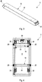
- the support means 18 comprise two support elements 20, which are designed in the manner of rollers and are fixed to a carrier element 22.
- the support means 18 are fixed on the base of the interchangeable container 4 via the carrier elements 22.
- the support elements 20 of the support means 18 rest on the guide surfaces 16 of the guide means 14 when the interchangeable container 4 is arranged in the receiving area 6.
- the interchangeable container 4 When transferring and arranging the interchangeable container 4 in the receiving area 6 of the vehicle 8, the interchangeable container 4 is supported by the support means 18 on the guide surfaces 16 and can be slid or unrolled against movement transversely to the direction of transfer.
- the guide surfaces 16 are inclined with respect to the receiving base 12.
- the securing device 2 comprises an adjustment unit 24 through which the inclination of the guide surface 16 with respect to the receiving sheet 12 is adjustable.
- the figures show an exemplary embodiment of the securing device 2 in which the guide means 14 are releasably secured to the support structure 10 of the vehicle 6.
- the support means 18 are also releasably attached to the interchangeable container 4.
- Guide means 14 and support means 18 are arranged on a surface of the interchangeable container 4 facing the receiving base 12, whereby the distance from the receiving base 12 is minimal.
- two guide means 14 are provided in the exemplary embodiment shown in the figures, which are arranged on opposite sides with respect to the interchangeable container 4. As a result, the interchangeable container 4 is held on both sides by the guide means 14.
- the fixing device 2 comprises a bolt-like holding means 26 which is fixed in the receiving base 12.
- the bolt-like holding means 26 can engage in a correspondingly designed receptacle 28 in the interchangeable container 4 when the interchangeable container 4 is arranged in the receiving area 6.
- the holding means 26 is preloaded into a blocking position by a restoring means not shown in the figures, in which the holding means 26 engages in the receptacle 28.
- the holding means 26 can be transferred from the blocking position into a release position in which the holding means 26 is out of engagement with the receptacle 28 in the interchangeable container 4.
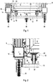
- Figure 1 shows a view of a region of the vehicle 8.
- this includes a cargo bike.
- the vehicle 8 comprises three wheels 30 with which the vehicle 8 can be driven on a roadway.
- the swap body 4 in turn comprises rollers 32, with which the interchangeable container 4 can be brought into the receiving area 6 via a ramp, for example.
- Figure 2 shows a detailed view of an area according to Figure 1 .
- FIG 3 shows a detailed view of the support means 18 from Figure 3 it can be seen that the support means 18 comprises a carrier element 22, at the free ends of which the roller-like support elements 20 are formed.
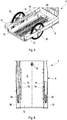
- the Figures 5 and 6 show a receiving area 6 of the vehicle 8.
Abstract
Die Erfindung betrifft eine Festlegevorrichtung (2) zum Festlegen eines Wechselbehälters (4) in oder an einem Aufnahmebereich (6) eines Fahrzeugs (8), mit mindestens einer im Aufnahmebereich (6) angeordneten Stützstruktur (10), mit mindestens einem im Aufnahmebereich (6) angeordneten Aufnahmeboden (12), mit mindestens einem zum Aufnahmeboden (12) beabstandeten schienenartigen Führungsmittel (14), das an der Stützstruktur (10) oder am Wechselbehälter (4) festgelegt ist und das eine Führungsfläche (16) aufweist, und mit mindestens einem am Wechselbehälter (4), bzw. an der Stützstruktur (10) angeordneten Stützmittel (18), das beim Überführen des Wechselbehälters (4) in den Aufnahmebereich (6) oder aus dem Aufnahmebereich (6) zwischen dem Führungsmittel (14) und dem Aufnahmeboden (12) angeordnet ist und zumindest abschnittsweise an der Führungsfläche (16) des schienenartigen Führungsmittels (14) berührend gleitbar oder abrollbar und gegen ein Bewegen quer zur Überführungsrichtung abstützbar oder abgestützt ist. Sie ist dadurch gekennzeichnet, dass zumindest die Führungsfläche (16) des mindestens einen Führungsmittels (14) bezüglich des Aufnahmebodens (12) eine Neigung aufweist.The invention relates to a securing device (2) for securing a swap body (4) in or on a receiving area (6) of a vehicle (8), with at least one support structure (10) arranged in the receiving area (6), with at least one in the receiving area (6) ) arranged receiving base (12), with at least one rail-like guide means (14) which is spaced apart from the receiving base (12) and which is fixed to the support structure (10) or to the swap container (4) and which has a guide surface (16), and with at least one on the interchangeable container (4) or on the support structure (10) arranged support means (18), which when transferring the interchangeable container (4) into the receiving area (6) or from the receiving area (6) between the guide means (14) and the receiving base (12) is arranged and at least in sections on the guide surface (16) of the rail-like guide means (14) can be slid or rolled in contact and supported against movement transversely to the transfer direction r or is supported. It is characterized in that at least the guide surface (16) of the at least one guide means (14) has an inclination with respect to the receiving base (12).
Description
Die Erfindung betrifft eine Festlegevorrichtung zum Festlegen eines Wechselbehälters in oder an einem Aufnahmebereich eines Fahrzeugs, mit mindestens einer im Aufnahmebereich angeordneten Stützstruktur, mit mindestens einem im Aufnahmebereich angeordneten Aufnahmeboden, mit mindestens einem zum Aufnahmeboden beabstandeten schienenartigen Führungsmittel, das an der Stützstruktur oder am Wechselbehälter festgelegt ist und das eine Führungsfläche aufweist, und mit mindestens einem am Wechselbehälter bzw. an der Stützstruktur angeordneten Stützmittel, das beim Überführen des Wechselbehälters in den Aufnahmebereich oder aus dem Aufnahmebereich zwischen dem Führungsmittel und dem Aufnahmeboden angeordnet ist und zumindest abschnittsweise an der Führungsfläche des schienenartigen Führungsmittels berührend gleitbar oder abrollbar und gegen ein Bewegen quer zur Überführungsrichtung abstützbar oder abgestützt ist, sowie ein Fahrzeug mit einer derartigen Festlegevorrichtung.The invention relates to a securing device for securing a swap body in or on a receiving area of a vehicle, with at least one support structure arranged in the receiving area, with at least one receiving base arranged in the receiving area, with at least one rail-like guide means spaced from the receiving base, which is fixed to the support structure or the interchangeable container and which has a guide surface, and with at least one support means arranged on the swap body or on the support structure, which is arranged between the guide means and the receiving base when the swap body is transferred into the receiving area or from the receiving area, and at least in sections on the guide surface of the rail-like guide means is slidable or rollable in contact and can be or is supported against moving transversely to the transfer direction, as well as a vehicle with such a fixing device.
Aus dem Stand der Technik sind Fahrzeuge bekannt, mit denen Wechselbehälter transportierbar sind, bei denen zum Festlegen der Wechselbehälter U-Profile im Aufnahmebereich angeordnet sind, in denen die Wechselbehälter mit ihren Rollen geführt anordenbar sind. Die Führung erfolgt über die Seitenwände der U-Profile, die direkt mit den Flanken der Rollen der Wechselbehälter in Kontakt stehen. Bei einer derartigen Festlegevorrichtung hat es sich als nachteilig herausgestellt, dass die Rollen der Wechselbehälter einem hohen Verschleiß unterliegen sowie stets ein identischer Radstand der Vorder- und Hinterräder der Wechselbehälter notwendig ist.From the prior art, vehicles are known with which swap bodies can be transported, in which U-profiles are arranged in the receiving area to fix the swap bodies, in which the swap bodies can be arranged with their rollers in a guided manner. The guide takes place via the side walls of the U-profiles, which are in direct contact with the flanks of the rollers of the swap bodies. In such a securing device it has been found to be disadvantageous that the rollers of the swap bodies are subject to high wear and an identical wheelbase of the front and rear wheels of the swap bodies is always necessary.
Darüber hinaus sind Fahrzeuge zum Transport von Wechselbehältern bekannt, bei denen die Wechselbehälter beim Überführen in den Aufnahmebereich nicht oder nur unzureichend geführt werden und über einen Formschluss festgelegt werden. Hierbei hat es sich als nachteilig herausgestellt, den Wechselbehälter auch bei schlechter Einblicknahme auf den Aufnahmebereich so auszurichten, dass der Formschluss herstellbar ist.In addition, vehicles for transporting swap bodies are known in which the swap bodies are not or only insufficiently guided when they are transferred into the receiving area and are fixed by means of a form fit. It has been found to be disadvantageous here to align the interchangeable container so that the interlocking connection can be established, even if the viewing area is poor.
Ferner kann beim Fahren mit dem Fahrzeug über Unebenheiten in der Fahrbahn eine Relativbewegung zwischen Wechselbehälter und Aufnahmebereich in Richtung quer zum Aufnahmeboden aufgrund von Trägheitskräften nie ganz vermieden werden, was zu Beschädigungen am Wechselbehälter und/oder dem Aufnahmeboden führen kann.Furthermore, when driving the vehicle over bumps in the roadway, a relative movement between the swap body and the receiving area in the direction transverse to the receiving base due to inertial forces can never be completely avoided, which can lead to damage to the interchangeable container and / or the receiving base.
Eine Aufgabe eines Ausführungsbeispiels der Erfindung ist, ein Anordnen und Festlegen eines Wechselbehälters in oder an einem Aufnahmebereich eines Fahrzeugs zu erleichtern und zu verbessern.One object of an exemplary embodiment of the invention is to facilitate and improve the arrangement and fixing of a swap body in or on a receiving area of a vehicle.
Diese Aufgabe wird bei einer eingangs genannten Festlegevorrichtung dadurch gelöst, dass zumindest die Führungsfläche des mindestens einen Führungsmittels bezüglich des Aufnahmebodens eine Neigung aufweist.This object is achieved in a fixing device mentioned at the outset in that at least the guide surface of the at least one guide means has an incline with respect to the receiving base.
Dadurch, dass zumindest die Führungsfläche des mindestens einen Führungsmittels bezüglich des Aufnahmebodens eine Neigung aufweist, ist der Wechselbehälter in zwei Richtungen quer zur Überführungsrichtung gehalten. Hierdurch ist gewährleistet, dass der Wechselbehälter nicht nur bei Kurvenfahrten, sondern auch bei Unebenheiten der Fahrbahn am Aufnahmeboden anliegt und relativ zur Stützstruktur im Wesentlichen ortsfest festgelegt ist.Because at least the guide surface of the at least one guide means is inclined with respect to the receiving base, the interchangeable container is held in two directions transverse to the transfer direction. This ensures that the swap body not only rests against the receiving floor when cornering but also when the roadway is uneven and is essentially fixed in place relative to the support structure.
Der Wechselbehälter kann beispielsweise mittels Reifen oder Rollen in oder an dem Aufnahmebereich angeordnet werden. Hierzu kann bei einer Ausführungsform der Festlegevorrichtung eine Rampe vorgesehen sein, mit der der Wechselbehälter auf dem Aufnahmeboden des Aufnahmebereichs rollbar ist. Hierdurch kann ein Höhenunterschied zwischen Fahrbahn und Aufnahmeboden überwunden werden.The interchangeable container can be arranged in or on the receiving area by means of tires or rollers, for example. For this purpose, in one embodiment of the securing device, a ramp can be provided with which the interchangeable container can be rolled on the receiving base of the receiving area. In this way, a difference in height between the roadway and the receiving floor can be overcome.
Darüber hinaus ist es denkbar, dass der Wechselbehälter auf Kufen oder Dergleichen auf den Aufnahmeboden des Aufnahmebereichs anordenbar ist.In addition, it is conceivable that the interchangeable container can be arranged on runners or the like on the receiving base of the receiving area.
Durch das Vorsehen der Führungsmittel ist der Wechselbehälter linear führbar.By providing the guide means, the swap body can be guided linearly.
Die Überführungsrichtung kann parallel zu einer Fahrzeuglängsachse oder einer Fahrzeugquerachse erfolgen. Darüber hinaus sind Zwischenformen denkbar, beispielsweise, dass die Überführungsrichtung schräg zur Fahrzeuglängsachse verläuft.The transfer direction can be parallel to a vehicle longitudinal axis or a vehicle transverse axis. In addition, intermediate forms are conceivable, for example that the transfer direction runs obliquely to the longitudinal axis of the vehicle.
Bei dem Fahrzeug kann es sich um ein beliebiges Fahrzeug handeln, insbesondere ein Landfahrzeug, Wasserfahrzeug und/oder Luftfahrzeug. Wenn es sich bei dem Fahrzeug um ein Landfahrzeug handelt, kann es sich um einen Personenkraftwagen, einen Lastkraftwagen oder um ein Neigefahrzeug handeln. Unter einem Neigefahrzeug werden Fahrräder; Pedelecs, Motorräder oder motorradähnliche Kraftfahrzeuge, wie Motorroller, insbesondere zwei-, drei- oder vierrädrige Motorroller, Scooter, neigbare Trikes, Quads oder Dergleichen verstanden.The vehicle can be any vehicle, in particular a land vehicle, watercraft and / or aircraft. If the vehicle is a land vehicle, it can be a passenger car, a truck, or a tilting vehicle. Under a tilting vehicle are bicycles; Pedelecs, motorcycles or motor vehicles similar to motorcycles, such as motor scooters, in particular two-, three- or four-wheeled scooters, scooters, tiltable trikes, quads or the like.
Wenn das Fahrzeug ein Neigefahrzeug umfasst, erweist es sich als vorteilhaft, wenn dieses einen Fahrerbereich und einen in Fahrtrichtung davor oder dahinter angeordneten einen lastaufnehmenden Aufnahmebereich umfasst.If the vehicle comprises a tilting vehicle, it proves to be advantageous if this comprises a driver's area and a load-absorbing receiving area arranged in front of or behind in the direction of travel.
Um die Aufnahme unterschiedlicher Wechselbehälter auf einfache Weise gewährleisten zu können, ist bei einer Ausführungsform der Festlegevorrichtung eine Einstelleinheit vorgesehen, durch die die Neigung der Führungsfläche des Führungsmittels bezüglich des Aufnahmebodens stufenweise oder stufenlos einstellbar ist.In order to be able to ensure that different interchangeable containers can be accommodated in a simple manner, an adjustment unit is provided in one embodiment of the fixing device, by means of which the inclination of the guide surface of the guide means with respect to the receiving base can be adjusted stepwise or continuously.
Zudem lässt sich das Anpassen der Festlegevorrichtung für eine Vielzahl von Wechselbehältern weiterverbessern, wenn die Festlegevorrichtung mindestens eine Spanneinheit umfasst, die mindestens ein Spannmittel umfasst, durch das das Führungsmittel in Richtung auf das Stützmittel und/oder durch das das Stützmittel in Richtung auf das Führungsmittel spannbar ist.In addition, the adaptation of the securing device for a plurality of interchangeable containers can be further improved if the securing device comprises at least one tensioning unit which comprises at least one tensioning means through which the guide means in the direction of the support means and / or by which the support means can be tensioned in the direction of the guide means.
Die Spanneinheit und die Einstelleinheit können eine gemeinsame Komponente umfassen. Ferner ist es denkbar, dass Einstelleinheit und Spanneinheit voneinander separate oder separierbare Bauteile umfassen.The tensioning unit and the adjustment unit can comprise a common component. Furthermore, it is conceivable that the setting unit and the tensioning unit comprise components that are separate or separable from one another.
Es erweist sich als vorteilhaft, wenn das Führungsmittel und die Stützstruktur oder wenn das Führungsmittel und der Wechselbehälter lösbar oder unlösbar aneinander festlegbar oder festgelegt sind oder ein gemeinsames Bauteil umfassen und/oder wenn das Stützmittel und die Stützstruktur oder wenn das Stützmittel und der Wechselbehälter lösbar oder unlösbar aneinander festlegbar oder festgelegt sind oder ein gemeinsames Bauteil umfassen.It proves to be advantageous if the guide means and the support structure or if the guide means and the interchangeable container are detachably or non-detachably fixable or fixed to one another or comprise a common component and / or if the support means and the support structure or if the support means and the interchangeable container are detachable or are inextricably fixed or fixed to one another or comprise a common component.
Wenn das Führungsmittel und die Stützstruktur oder das Führungsmittel und der Wechselbehälter lösbar oder unlösbar aneinander festlegbar oder festgelegt sind, kann das Führungsmittel auf einfache Weise ausgetauscht oder repariert werden. Wenn das Führungsmittel und die Stützstruktur oder das Führungsmittel und der Wechselbehälter ein gemeinsames Bauteil umfassen, kann die Festlegevorrichtung bauteilreduziert ausgebildet sein.If the guide means and the support structure or the guide means and the interchangeable container can be fixed or fixed to one another in a detachable or non-detachable manner, the guide means can be exchanged or repaired in a simple manner. If the guide means and the support structure or the guide means and the interchangeable container comprise a common component, the securing device can be designed with fewer components.
Gleiches gilt entsprechend für das Stützmittel.The same applies accordingly to the proppant.
Das Führungsmittel und das Stützmittel können grundsätzlich auf einer beliebigen Höhe bezüglich des Aufnahmebodens angeordnet sein. Es erweist sich als vorteilhaft, wenn das Führungsmittel und das Stützmittel auf Höhe einer dem Aufnahmeboden zugewandten Oberfläche des Wechselbehälters angeordnet sind, deren Abstand zum Aufnahmeboden minimal ist.The guide means and the support means can in principle be arranged at any desired height with respect to the receiving base. It has proven to be advantageous if the guide means and the support means are arranged at the level of a surface of the interchangeable container which faces the receiving base and whose distance from the receiving base is minimal.
Bei einer Weiterbildung der Festlegevorrichtung ist vorgesehen, dass das Stützmittel mindestens ein Stützelement umfasst, das zumindest abschnittsweise an der Führungsfläche des schienenartigen Führungsmittels berührend gleitbar oder abrollbar ist und insbesondere eine Kufe oder eine Rolle umfasst und/oder dass das Stützmittel mindestens ein Trägerelement umfasst, mit dem das Stützmittel am Wechselbehälter oder an der Stützstruktur festlegbar ist und an dessen einem Ende das Stützelement anordenbar ist.In a further development of the securing device, it is provided that the support means comprises at least one support element which is at least partially slidable or unrollable on the guide surface of the rail-like guide means and in particular comprises a runner or a roller and / or that the support means comprises at least one carrier element with the support means on the swap body or on the Support structure can be fixed and at one end of which the support element can be arranged.
Durch das Vorsehen eines Stützelements und eines Trägerelements kann das Stützmittel auf einfache Weise am Wechselbehälter oder an der Stützstruktur festgelegt werden. Das Stützelement kann beispielsweise kufenartig ausgebildet sein und an der Führungsfläche des Führungsmittels beim Überführen des Wechselbehälters in den Aufnahmebereich oder aus dem Aufnahmebereich heraus berührend entlanggleiten. Darüber hinaus kann das Stützelement rollenartig ausgebildet sein und entlang des Führungsmittels abrollen. Solchenfalls ist das rollenartig ausgebildete Stützelement mittels eines Lagers an dem Trägerelement festgelegt.By providing a support element and a carrier element, the support means can be fixed in a simple manner on the interchangeable container or on the support structure. The support element can, for example, be designed in the manner of a runner and slide along the guide surface of the guide means in a touching manner when the interchangeable container is transferred into the receiving area or out of the receiving area. In addition, the support element can be designed like a roller and roll along the guide means. In such a case, the roller-like support element is fixed to the carrier element by means of a bearing.
Grundsätzlich kann das Führungsmittel sowohl an der Stützstruktur des Aufnahmebereichs als auch am Wechselbehälter angeordnet sein. Das Stützmittel ist hierbei an dem jeweils anderen Bauteil angeordnet. Mit anderen Worten, wenn das Führungsmittel an der Stützstruktur des Aufnahmebereichs angeordnet ist, ist das Stützmittel am Wechselbehälter angeordnet. Wenn das Führungsmittel am Wechselbehälter angeordnet ist, ist das Stützmittel an der Stützstruktur des Aufnahmebereichs angeordnet.In principle, the guide means can be arranged both on the support structure of the receiving area and on the interchangeable container. The support means is arranged on the respective other component. In other words, when the guide means is arranged on the support structure of the receiving area, the support means is arranged on the interchangeable container. If the guide means is arranged on the interchangeable container, the support means is arranged on the support structure of the receiving area.
Bei einer Ausführungsform der Festlegevorrichtung ist vorgesehen, dass mindestens ein Führungsmittel an der Stützstruktur des Aufnahmebereichs angeordnet ist und/oder dass mindestens ein Stützmittel am Wechselbehälter angeordnet ist.In one embodiment of the securing device it is provided that at least one guide means is arranged on the support structure of the receiving area and / or that at least one support means is arranged on the interchangeable container.
Um die Stabilität der Anordnung des Wechselbehälters innerhalb des Aufnahmebereichs weiter zu erhöhen, sind bei einer Ausführungsform der Festlegevorrichtung mindestens zwei Führungsmittel und mindestens zwei Stützmittel vorgesehen, die jeweils auf einander gegenüberliegenden Seiten angeordnet sind und der Wechselbehälter zwischen den beiden Führungsmitteln und Stützmitteln angeordnet ist.In order to further increase the stability of the arrangement of the interchangeable container within the receiving area, at least two guide means and at least two support means are provided in one embodiment of the securing device, which are each arranged on opposite sides and the interchangeable container is arranged between the two guide means and support means.
Grundsätzlich ist es denkbar, dass die beiden Führungsmittel und die beiden Stützmittel jeweils auf der gleichen Seite des Wechselbehälters angeordnet sind. Solchenfalls können diese in unterschiedlicher Höhe zueinander angeordnet sein. Ferner ist es denkbar, dass die Führungsmittel jeweils auf unterschiedlichen Seiten des Wechselbehälters angeordnet sind. Hierdurch ist die Stabilität des Wechselbehälters beim Anordnen im Aufnahmebereich weiter erhöht. Die beiden Führungsmittel, bzw. die beiden Stützmittel, können auf gleicher Höhe, insbesondere mit gleichem Abstand zum Aufnahmeboden, angeordnet sein oder unterschiedliche Höhe, insbesondere Abstand zum Fahrzeugboden, umfassen.In principle, it is conceivable that the two guide means and the two support means are each arranged on the same side of the interchangeable container. In such a case, these can be at different heights to each other be arranged. It is also conceivable that the guide means are each arranged on different sides of the interchangeable container. This further increases the stability of the interchangeable container when it is arranged in the receiving area. The two guide means, or the two support means, can be arranged at the same height, in particular at the same distance from the receiving floor, or can have different heights, in particular the distance from the vehicle floor.
Es erweist sich als vorteilhaft, wenn das Stützmittel mindestens zwei Stützelemente umfasst, die an einander gegenüberliegenden Seiten des Trägerelements angeordnet sind und
über die Breite des Wechselbehälters - quer zur Überführungsrichtung betrachtet - erstreckt ist.
Solchenfalls kann das Stützmittel sich an zwei einander gegenüberliegenden Führungsmitteln abstützen. Hierdurch ist die Festlegevorrichtung bauteilreduziert ausbildbar.It proves to be advantageous if the support means comprises at least two support elements which are arranged on opposite sides of the carrier element and
Over the width of the interchangeable container - viewed transversely to the transfer direction - extends.
In such a case, the support means can be supported on two mutually opposite guide means. As a result, the securing device can be designed with fewer components.
Um ein Anordnen des Wechselbehälters am Aufnahmebereich zu erleichtern, erweist es sich als vorteilhaft, wenn die Festlegevorrichtung mindestens eine Zentrierungseinheit umfasst, die zumindest die mindestens zwei Führungsmittel umfasst, die zusammen einen trichterartigen Abschnitt umfassen, durch den der Wechselbehälter beim Überführen auf oder in den Aufnahmebereich im wesentlich mittig im Aufnahmebereich angeordnet wird.In order to facilitate the arrangement of the interchangeable container on the receiving area, it proves to be advantageous if the securing device comprises at least one centering unit which comprises at least the at least two guide means, which together comprise a funnel-like section through which the interchangeable container when being transferred to or into the receiving area is arranged essentially centrally in the receiving area.
Hierdurch ist auf einfache Weise eine Führung des Wechselbehälters beim Überführen in den Aufnahmebereich gewährleistet.This ensures that the interchangeable container is guided in a simple manner when it is transferred into the receiving area.
Um den Wechselbehälter nach dem Anordnen im Aufnahmebereich gegen ein Bewegen in oder entgegen der Überführungsrichtung festzulegen, ist bei einer Ausführungsform der Festlegevorrichtung mindestens ein an der Stützstruktur oder am Wechselbehälter angeordnetes Haltemittel vorgesehen, das von einer Sperrstellung, in der es in eine Aufnahme am Wechselbehälter bzw. an der Stützstruktur eingreift und den Wechselbehälter gegen ein Bewegen in Überführungsrichtung festlegt, in eine Freigabestellung überführbar ist, in der der Wechselbehälter für ein Bewegen in Überführungsrichtung freigegeben ist.In order to fix the interchangeable container after it has been arranged in the receiving area against moving in or against the transfer direction, in one embodiment of the securing device at least one holding means is provided which is arranged on the support structure or on the interchangeable container engages the support structure and fixes the swap body against moving in the transfer direction, can be transferred into a release position in which the swap body is released for movement in the transfer direction.
Das Haltemittel kann einen Form- oder Kraftschluss zwischen Wechselbehälter und Aufnahmebereich herstellen.The holding means can produce a form fit or a force fit between the interchangeable container and the receiving area.
Bei einer Weiterbildung letztgenannter Ausführungsform erweist es sich als vorteilhaft, wenn das Haltemittel bolzenartig ausgebildet ist und in oder quer zur Überführungsrichtung von der Sperrstellung in die Freigabestellung und zurück überführbar ist.In a further development of the last-mentioned embodiment, it proves to be advantageous if the holding means is designed in the manner of a bolt and can be transferred from the blocking position to the release position and back in or across the transfer direction.
Hierdurch ist das Haltemittel einfach und kostengünstig herstellbar.As a result, the holding means can be produced easily and inexpensively.
Darüber hinaus erweist es sich bei einer weiteren Weiterbildung als vorteilhaft, wenn das Haltemittel am Aufnahmeboden des Aufnahmebereichs angeordnet ist und quer zur Überführungsrichtung von der Sperrstellung in die Freigabestellung und zurück überführbar ist und/oder wenn das Haltemittel mindestens ein Rückstellmittel umfasst, durch das das Haltemittel in die Sperrstellungen vorspannbar ist.In addition, it proves to be advantageous in a further development if the holding means is arranged on the receiving base of the receiving area and can be transferred from the blocking position to the release position and back transversely to the transfer direction and / or if the holding means comprises at least one restoring means through which the holding means can be biased into the locked positions.
Hierdurch kann gewährleistet werden, dass das Haltemittel automatisch mit dem Wechselbehälter verrastet, sobald sich dieser im Aufnahmebereich befindet.This can ensure that the holding means automatically latches with the swap container as soon as it is in the receiving area.
Zum Lösen des Haltemittels kann am Haltemittel ein mechanisches oder elektromechanisches Entriegelungsmittel vorgesehen sein, das beispielsweise durch einen Benutzer des Fahrzeugs manuell betätigbar ist, um den Wechselbehälter vom Haltemittel zu lösen.To release the holding means, a mechanical or electromechanical unlocking means can be provided on the holding means, which, for example, can be actuated manually by a user of the vehicle in order to release the interchangeable container from the holding means.
Um Fertigungstoleranzen des Wechselbehälters, insbesondere der Aufnahme und des Haltemittels auszugleichen, ist bei einer Ausführungsform der Festlegevorrichtung vorgesehen, dass die Aufnahme eine sich in Überführungsrichtung verjüngende Kontur umfasst, an der das Haltemittel in der Sperrstellung anliegt.In order to compensate for manufacturing tolerances of the interchangeable container, in particular of the receptacle and the holding means, one embodiment of the securing device provides that the receptacle comprises a contour which tapers in the transfer direction and against which the holding means rests in the blocking position.
Hierdurch kann eine im Wesentlichen spielfreies Festlegen des Haltemittels in der Aufnahme gewährleistet werden.As a result, the holding means can be fixed in the receptacle with essentially no play.
Schließlich wird die Aufgabe gelöst durch ein Fahrzeug mit einem Aufnahmebereich in dem ein Wechselbehälter durch eine Festlegevorrichtung mit mindestens einem der zuvor genannten Merkmale festlegbar ist, welche mindestens eine im Aufnahmebereich angeordnete Stützstruktur, welche mindestens einen im Aufnahmebereich angeordneten Aufnahmeboden, welche mindestens ein zum Aufnahmeboden beabstandetes schienenartiges Führungsmittel, das an der Stützstruktur oder am Wechselbehälter festgelegt ist und das eine Führungsfläche aufweist, und welche mindestens ein am Wechselbehälter bzw. an der Stützstruktur angeordnetes Stützmittel umfasst, das beim Überführen des Wechselbehälters in den Aufnahmebereich oder aus dem Aufnahmebereich zwischen dem Führungsmittel und dem Aufnahmeboden angeordnet ist und zumindest abschnittsweise an der Führungsfläche des schienenartigen Führungsmittels berührend gleitbar oder abrollbar und gegen ein Bewegen quer zur Überführungsrichtung abstützbar oder abgestützt ist, wobei zumindest die Führungsfläche des mindestens einen Führungsmittels bezüglich des Aufnahmebodens eine Neigung aufweist.Finally, the object is achieved by a vehicle with a receiving area in which a swap body can be fixed by a fixing device with at least one of the aforementioned features, which has at least one support structure arranged in the receiving area, which has at least one receiving base arranged in the receiving area, which is at least one spaced apart from the receiving base rail-like guide means which is fixed on the support structure or on the swap body and which has a guide surface, and which comprises at least one support means arranged on the swap body or on the support structure, which when transferring the swap body into the receiving area or from the receiving area between the guide means and the Receiving base is arranged and at least in sections on the guide surface of the rail-like guide means is slidable or rollable in contact and can be or is supported against moving transversely to the transfer direction wherein at least the guide surface of the at least one guide means has an inclination with respect to the receiving base.
Weitere Merkmale, Einzelheiten und Vorteile der Erfindung ergeben sich aus den beigefügten Patentansprüchen, aus der zeichnerischen Darstellung und nachfolgenden Beschreibung einer bevorzugten Ausführungsform der Festlegevorrichtung.Further features, details and advantages of the invention emerge from the attached patent claims, from the drawing and the following description of a preferred embodiment of the securing device.
In der Zeichnung zeigt:
Figur 1- Eine ausschnittsweise Rückansicht auf ein Fahrzeug mit einer erfindungsgemäßen Festlegevorrichtung;
Figur 2- Eine Detailansicht eines Bereichs gemäß
Figur 1 ; - Figur 3
- Eine perspektivische Draufsicht auf ein Stützmittel einer Festlegevorrichtung;
Figur 4- Eine Unteransicht auf einen Wechselbehälter mit zwei Stützmitteln;
- Figur 5
- Eine perspektivische Draufsicht auf einen Aufnahmebereich des Fahrzeugs;
Figur 6- Eine Draufsicht auf den Aufnahmebereich des Fahrzeugs gemäß
Figur 5 .
- Figure 1
- A partial rear view of a vehicle with a securing device according to the invention;
- Figure 2
- A detailed view of an area according to
Figure 1 ; - Figure 3
- A perspective top view of a support means of a securing device;
- Figure 4
- A bottom view of a swap body with two support means;
- Figure 5
- A perspective top view of a receiving area of the vehicle;
- Figure 6
- A top view of the receiving area of the vehicle according to FIG
Figure 5 .
Die Figuren zeigen eine insgesamt mit dem Bezugszeichen 2 versehene Festlegevorrichtung zum Festlegen eines Wechselbehälters 4 in oder an einem Aufnahmebereich 6 eines Fahrzeugs 8. Im Aufnahmebereich 6 des Fahrzeugs 8 ist eine Stützstruktur 10 angeordnet. Ferner umfasst der Aufnahmebereich 6 des Fahrzeugs 8 einen im Aufnahmebereich 6 angeordneten Aufnahmeboden 12.The figures show a fixing device, provided overall with the
Die Festlegevorrichtung 2 umfasst mindestens ein zum Aufnahmeboden 12 beabstandetes, schienenartiges Führungsmittel 14. Bei den in den Figuren gezeigten Ausführungsbeispielen ist das schienenartige Führungsmittel an der Stützstruktur 10 des Fahrzeugs 8 festgelegt. Das Führungsmittel 14 umfasst eine Führungsfläche 16. Darüber hinaus umfasst die Festlegevorrichtung 2 Stützmittel 18, die bei den in den Figuren gezeigten Ausführungsbeispielen am Wechselbehälter 4 festgelegt sind. Die Stützmittel 18 umfassen zwei Stützelemente 20, die rollenartig ausgebildet sind und an einem Trägerelement 22 festgelegt sind. Die Stützmittel 18 sind über die Trägerelemente 22 am Boden des Wechselbehälters 4 festgelegt. Darüber hinaus liegen die Stützelemente 20 des Stützmittels 18 an den Führungsflächen 16 der Führungsmittel 14 an, wenn der Wechselbehälter 4 im Aufnahmebereich 6 angeordnet ist.The securing
Beim Überführen und Anordnen des Wechselbehälters 4 im Aufnahmebereich 6 des Fahrzeugs 8, stützt sich der Wechselbehälter 4 über die Stützmittel 18 an den Führungsflächen 16 ab und ist an diesen berührend gleitbar oder abrollbar gegen ein Bewegen quer zur Überführungsrichtung gestützt. Die Führungsfläche 16 sind bezüglich des Aufnahmebodens 12 geneigt.When transferring and arranging the
Um die Neigung der Führungsfläche 16 des Führungsmittels 14 einstellen zu können, umfasst die Festlegevorrichtung 2 eine Einstelleinheit 24, durch die die Neigung der Führungsfläche 16 bezüglich des Aufnahmebogens 12 einstellbar ist.In order to be able to adjust the inclination of the
Die Figuren zeigen ein Ausführungsbeispiel der Festlegevorrichtung 2, bei der die Führungsmittel 14 an der Stützstruktur 10 des Fahrzeugs 6 lösbar festgelegt sind. Auch die Stützmittel 18 sind lösbar am Wechselbehälter 4 festgelegt.The figures show an exemplary embodiment of the securing
Führungsmittel 14 und Stützmittel 18 sind an einer dem Aufnahmeboden 12 zugewandten Oberfläche des Wechselbehälters 4 angeordnet, wodurch der Abstand zum Aufnahmeboden 12 minimal ist.Guide means 14 and support means 18 are arranged on a surface of the
Um ein Führen des Wechselbehälters beim Überführen in den Aufnahmebereich 6 zu gewährleisten, sind bei dem in den Figuren gezeigten Ausführungsbeispiel zwei Führungsmittel 14 vorgesehen, die aufeinander gegenüberliegenden Seiten bezüglich des Wechselbehälters 4 angeordnet sind. Hierdurch ist der Wechselbehälter 4 beidseits durch die Führungsmittel 14 gehalten.In order to ensure that the interchangeable container is guided when it is transferred into the receiving
Um den Wechselbehälter 4 gegen ein Bewegen in Überführungsrichtung festzulegen, umfasst die Festlegevorrichtung 2 ein bolzenartiges Haltemittel 26, das im Aufnahmeboden 12 festgelegt ist. Das bolzenartige Haltemittel 26 kann in einer korrespondierend ausgebildeten Aufnahme 28 im Wechselbehälter 4 eingreifen, wenn der Wechselbehälter 4 im Aufnahmebereich 6 angeordnet ist. Hierzu ist das Haltemittel 26 durch ein in den Figuren nicht ersichtliches Rückstellmittel in eine Sperrstellung vorgespannt, in der das Haltemittel 26 in die Aufnahme 28 eingreift. Um den Wechselbehälter 4 aus dem Aufnahmebereich 6 zu entfernen, ist das Haltemittel 26 von der Sperrstellung in eine Freigabestellung überführbar, in der das Haltemittel 26 außer Eingriff mit der Aufnahme 28 im Wechselbehälter 4 ist.In order to fix the
Aus
Aus
Die
Die in der vorstehenden Beschreibung, in den Ansprüchen sowie in der Zeichnung offenbarten Merkmale der Erfindung, können sowohl einzeln, als auch in jeder beliebigen Kombination in der Verwirklichung der Erfindung in ihren verschiedenen Ausführungsformen wesentlich sein.The features of the invention disclosed in the above description, in the claims and in the drawing can be essential both individually and in any combination in the implementation of the invention in its various embodiments.
- 22
- FestlegevorrichtungLocking device
- 44th
- WechselbehälterSwap bodies
- 66th
- AufnahmebereichRecording area
- 88th
- Fahrzeugvehicle
- 1010
- StützstrukturSupport structure
- 1212
- AufnahmebodenReceiving base
- 1414th
- FührungsmittelGuide means
- 1616
- FührungsflächeGuide surface
- 1818th
- StützmittelProppants
- 2020th
- StützelementSupport element
- 2222nd
- TrägerelementSupport element
- 2424
- EinstelleinheitSetting unit
- 2626th
- HaltemittelHolding means
- 2828
- Aufnahmeadmission
- 3030th
- Räderbikes
- 3232
- Rollenroll
Claims (15)
Applications Claiming Priority (1)
| Application Number | Priority Date | Filing Date | Title |
|---|---|---|---|
| DE102019119691.4A DE102019119691B4 (en) | 2019-07-19 | 2019-07-19 | Fixing device for fixing an interchangeable container in or on a receiving area of a vehicle and vehicle with such a fixing device |
Publications (4)
| Publication Number | Publication Date |
|---|---|
| EP3766734A1 true EP3766734A1 (en) | 2021-01-20 |
| EP3766734C0 EP3766734C0 (en) | 2024-02-21 |
| EP3766734B1 EP3766734B1 (en) | 2024-02-21 |
| EP3766734B8 EP3766734B8 (en) | 2024-03-27 |
Family
ID=71119938
Family Applications (1)
| Application Number | Title | Priority Date | Filing Date |
|---|---|---|---|
| EP20181158.5A Active EP3766734B8 (en) | 2019-07-19 | 2020-06-19 | Locking device for locking an interchangeable container in or at a reception area of a vehicle and vehicle with such a locking device |
Country Status (5)
| Country | Link |
|---|---|
| US (1) | US11697368B2 (en) |
| EP (1) | EP3766734B8 (en) |
| CA (1) | CA3087374A1 (en) |
| DE (1) | DE102019119691B4 (en) |
| SG (1) | SG10202006548YA (en) |
Citations (3)
| Publication number | Priority date | Publication date | Assignee | Title |
|---|---|---|---|---|
| DE661878C (en) * | 1933-06-09 | 1938-08-22 | Hans Dietrich | Facility for container traffic |
| EP2420406A1 (en) * | 2010-08-16 | 2012-02-22 | Fahrzeugbau Karl Tang GmbH | Device for securing loads on a load surface of a vehicle structure |
| DE202016106717U1 (en) * | 2015-12-22 | 2017-01-13 | Ford Global Technologies, Llc | E-rail lashing system for a vehicle loading platform |
Family Cites Families (16)
| Publication number | Priority date | Publication date | Assignee | Title |
|---|---|---|---|---|
| US1360412A (en) * | 1917-03-22 | 1920-11-30 | River | Interchangeable-unit car |
| US1402211A (en) * | 1920-11-22 | 1922-01-03 | Cartmill Orrell Earl | Trunk attachment |
| US3817413A (en) * | 1969-11-12 | 1974-06-18 | R Ham | Demountable load carrying bodies |
| US4133440A (en) * | 1976-12-27 | 1979-01-09 | Heidrick Jr Joseph A | Trailer carrier |
| US4231695A (en) * | 1978-07-10 | 1980-11-04 | Weston Sr Robert M | Cargo loading and unloading apparatus for trucks |
| US4805859A (en) * | 1987-11-05 | 1989-02-21 | Don Hudson | Apparatus for securing containers to moving platforms |
| US5848869A (en) | 1996-12-03 | 1998-12-15 | Aesop, Inc. | Container restraining mechanism and method |
| US7172378B1 (en) * | 2005-08-24 | 2007-02-06 | Carl Cerullo | Adjustable stops for rolloff truck |
| DE102008030640A1 (en) | 2008-07-01 | 2010-01-07 | GE Fanuc Intelligent Platforms Embedded Systems, Inc. (n.d.Ges.d. Staates Delaware) | Fastening device for a housing in a receiving device |
| FR2977229B1 (en) | 2011-07-01 | 2015-06-05 | Meca System | TRICYCLE EQUIPPED WITH A LOADING BOX |
| US20140259837A1 (en) * | 2013-03-14 | 2014-09-18 | Carefusion 303, Inc. | Iv system to assist with line management |
| DE102014009780A1 (en) * | 2014-07-02 | 2016-01-07 | Björn Marc Paulus | Flexible transport system reversible swap bodies on three-wheeled (load) bicycles |
| DE102014114996A1 (en) * | 2014-10-15 | 2016-04-21 | Hilmar Ingwersen | System for variable loading of a vehicle |
| CA2867974C (en) | 2014-10-17 | 2023-03-21 | Mark Thygesen | Retractable cargo box assembly for a truck cargo bed |
| US10919428B2 (en) | 2015-08-07 | 2021-02-16 | Ford Global Technologies, Llc | Powered sliding platform assembly |
| US20180125060A1 (en) * | 2016-11-06 | 2018-05-10 | Seashell Technology, Llc | Articles of Manufacture And Related Methods To Create Insect Barriers |
-
2019
- 2019-07-19 DE DE102019119691.4A patent/DE102019119691B4/en active Active
-
2020
- 2020-06-19 EP EP20181158.5A patent/EP3766734B8/en active Active
- 2020-07-07 SG SG10202006548YA patent/SG10202006548YA/en unknown
- 2020-07-09 US US16/924,243 patent/US11697368B2/en active Active
- 2020-07-20 CA CA3087374A patent/CA3087374A1/en active Pending
Patent Citations (3)
| Publication number | Priority date | Publication date | Assignee | Title |
|---|---|---|---|---|
| DE661878C (en) * | 1933-06-09 | 1938-08-22 | Hans Dietrich | Facility for container traffic |
| EP2420406A1 (en) * | 2010-08-16 | 2012-02-22 | Fahrzeugbau Karl Tang GmbH | Device for securing loads on a load surface of a vehicle structure |
| DE202016106717U1 (en) * | 2015-12-22 | 2017-01-13 | Ford Global Technologies, Llc | E-rail lashing system for a vehicle loading platform |
Also Published As
| Publication number | Publication date |
|---|---|
| SG10202006548YA (en) | 2021-02-25 |
| CA3087374A1 (en) | 2021-01-19 |
| DE102019119691A1 (en) | 2021-01-21 |
| EP3766734C0 (en) | 2024-02-21 |
| EP3766734B1 (en) | 2024-02-21 |
| US20210016699A1 (en) | 2021-01-21 |
| US11697368B2 (en) | 2023-07-11 |
| DE102019119691B4 (en) | 2022-06-30 |
| EP3766734B8 (en) | 2024-03-27 |
Similar Documents
| Publication | Publication Date | Title |
|---|---|---|
| DE102009029750B4 (en) | Roof racks for motor vehicles for transporting bicycles | |
| DE102016101870A1 (en) | cargo bike | |
| DE102008035914A1 (en) | Transport system for use in goods transport train, has front and rear chassis parts connected over trolley clamp in manner such that goods carrier is insertable between front and rear chassis parts to both sides | |
| DE202008012180U1 (en) | transport system | |
| EP3176032B1 (en) | Traveling vehicle, in particular mobile home | |
| DE102019119691B4 (en) | Fixing device for fixing an interchangeable container in or on a receiving area of a vehicle and vehicle with such a fixing device | |
| DE202016006976U1 (en) | Holder for the secure transport of cargo inside a motor vehicle | |
| DE102016013093B4 (en) | Transport device for at least one two-wheeler, and method for loading a transport device with a two-wheeler | |
| DE102009017925A1 (en) | Bicycle trailer, has continuous rope, and slidably removable frame fastened at longitudinal trains of rope by two attachment handles that are mutually diagonal in proximity to opposite lying edges of bearing surfaces | |
| DE102018004209B4 (en) | Vehicle with drive module and load module | |
| DE102005039209B3 (en) | Uniaxial loading cart for use as e.g. trailer, has chassis designed such that track width of chassis is adjustable between narrow condition and broad condition in use condition of cart, where chassis is divided into two halves | |
| DE102016013557B3 (en) | Holder for the secure transport of cargo inside a motor vehicle | |
| DE202009005772U1 (en) | Bicycle trailer with extendable cargo area | |
| DE102019209580A1 (en) | Loading system for receiving a wheeled item | |
| DE102011122285A1 (en) | Load carrier with on a base support movably mounted load-bearing parts | |
| EP2607176B1 (en) | Load support with a load bearing part and a supporting element | |
| DE102004039552B4 (en) | Carriage for rail-bound transport of semi-trailers | |
| DE102008016282B3 (en) | snow vehicle | |
| DE202007000032U1 (en) | Commercial vehicle, preferably for camping, motorhomes or the like. | |
| EP1495951B1 (en) | Motor vehicle trailer for transporting a three wheeled vehicle | |
| DE202014105156U1 (en) | Vehicle trailer | |
| DE4435310C2 (en) | Device for the thrust support of a preceding single bicycle by a subsequent single bicycle | |
| DE102015006464B3 (en) | Bicycle mount as load securing for the transport of bicycles inside a motor vehicle | |
| DE202014100991U1 (en) | Device for transporting an object and kit | |
| DE2701812A1 (en) | Two-part cross-country vehicle - has central transverse hinge axis enabling vehicle to be folded for transport |
Legal Events
| Date | Code | Title | Description |
|---|---|---|---|
| PUAI | Public reference made under article 153(3) epc to a published international application that has entered the european phase |
Free format text: ORIGINAL CODE: 0009012 |
|
| STAA | Information on the status of an ep patent application or granted ep patent |
Free format text: STATUS: THE APPLICATION HAS BEEN PUBLISHED |
|
| AK | Designated contracting states |
Kind code of ref document: A1 Designated state(s): AL AT BE BG CH CY CZ DE DK EE ES FI FR GB GR HR HU IE IS IT LI LT LU LV MC MK MT NL NO PL PT RO RS SE SI SK SM TR |
|
| AX | Request for extension of the european patent |
Extension state: BA ME |
|
| STAA | Information on the status of an ep patent application or granted ep patent |
Free format text: STATUS: REQUEST FOR EXAMINATION WAS MADE |
|
| 17P | Request for examination filed |
Effective date: 20210720 |
|
| RBV | Designated contracting states (corrected) |
Designated state(s): AL AT BE BG CH CY CZ DE DK EE ES FI FR GB GR HR HU IE IS IT LI LT LU LV MC MK MT NL NO PL PT RO RS SE SI SK SM TR |
|
| STAA | Information on the status of an ep patent application or granted ep patent |
Free format text: STATUS: EXAMINATION IS IN PROGRESS |
|
| 17Q | First examination report despatched |
Effective date: 20211209 |
|
| GRAP | Despatch of communication of intention to grant a patent |
Free format text: ORIGINAL CODE: EPIDOSNIGR1 |
|
| STAA | Information on the status of an ep patent application or granted ep patent |
Free format text: STATUS: GRANT OF PATENT IS INTENDED |
|
| INTG | Intention to grant announced |
Effective date: 20230915 |
|
| GRAS | Grant fee paid |
Free format text: ORIGINAL CODE: EPIDOSNIGR3 |
|
| GRAA | (expected) grant |
Free format text: ORIGINAL CODE: 0009210 |
|
| STAA | Information on the status of an ep patent application or granted ep patent |
Free format text: STATUS: THE PATENT HAS BEEN GRANTED |
|
| AK | Designated contracting states |
Kind code of ref document: B1 Designated state(s): AL AT BE BG CH CY CZ DE DK EE ES FI FR GB GR HR HU IE IS IT LI LT LU LV MC MK MT NL NO PL PT RO RS SE SI SK SM TR |
|
| REG | Reference to a national code |
Ref country code: GB Ref legal event code: FG4D Free format text: NOT ENGLISH |
|
| REG | Reference to a national code |
Ref country code: CH Ref legal event code: PK Free format text: BERICHTIGUNG B8 Ref country code: CH Ref legal event code: EP |
|
| REG | Reference to a national code |
Ref country code: DE Ref legal event code: R096 Ref document number: 502020007059 Country of ref document: DE |
|
| RAP4 | Party data changed (patent owner data changed or rights of a patent transferred) |
Owner name: ONOMOTION GMBH |
|
| REG | Reference to a national code |
Ref country code: IE Ref legal event code: FG4D Free format text: LANGUAGE OF EP DOCUMENT: GERMAN |
|
| U01 | Request for unitary effect filed |
Effective date: 20240221 |
|
| U07 | Unitary effect registered |
Designated state(s): AT BE BG DE DK EE FI FR IT LT LU LV MT NL PT SE SI Effective date: 20240226 |