EP3766563A1 - Filter cloth, bag filter, gas processing apparatus equipped with same, and method for producing filter cloth - Google Patents
Filter cloth, bag filter, gas processing apparatus equipped with same, and method for producing filter cloth Download PDFInfo
- Publication number
- EP3766563A1 EP3766563A1 EP19768293.3A EP19768293A EP3766563A1 EP 3766563 A1 EP3766563 A1 EP 3766563A1 EP 19768293 A EP19768293 A EP 19768293A EP 3766563 A1 EP3766563 A1 EP 3766563A1
- Authority
- EP
- European Patent Office
- Prior art keywords
- filter cloth
- adsorbents
- filter
- activated carbon
- catalysts
- Prior art date
- Legal status (The legal status is an assumption and is not a legal conclusion. Google has not performed a legal analysis and makes no representation as to the accuracy of the status listed.)
- Withdrawn
Links
Images




Classifications
-
- B—PERFORMING OPERATIONS; TRANSPORTING
- B01—PHYSICAL OR CHEMICAL PROCESSES OR APPARATUS IN GENERAL
- B01J—CHEMICAL OR PHYSICAL PROCESSES, e.g. CATALYSIS OR COLLOID CHEMISTRY; THEIR RELEVANT APPARATUS
- B01J35/00—Catalysts, in general, characterised by their form or physical properties
- B01J35/40—Catalysts, in general, characterised by their form or physical properties characterised by dimensions, e.g. grain size
-
- B—PERFORMING OPERATIONS; TRANSPORTING
- B01—PHYSICAL OR CHEMICAL PROCESSES OR APPARATUS IN GENERAL
- B01D—SEPARATION
- B01D53/00—Separation of gases or vapours; Recovering vapours of volatile solvents from gases; Chemical or biological purification of waste gases, e.g. engine exhaust gases, smoke, fumes, flue gases, aerosols
- B01D53/34—Chemical or biological purification of waste gases
- B01D53/74—General processes for purification of waste gases; Apparatus or devices specially adapted therefor
- B01D53/86—Catalytic processes
- B01D53/8668—Removing organic compounds not provided for in B01D53/8603 - B01D53/8665
-
- B—PERFORMING OPERATIONS; TRANSPORTING
- B01—PHYSICAL OR CHEMICAL PROCESSES OR APPARATUS IN GENERAL
- B01D—SEPARATION
- B01D39/00—Filtering material for liquid or gaseous fluids
- B01D39/08—Filter cloth, i.e. woven, knitted or interlaced material
- B01D39/083—Filter cloth, i.e. woven, knitted or interlaced material of organic material
-
- B—PERFORMING OPERATIONS; TRANSPORTING
- B01—PHYSICAL OR CHEMICAL PROCESSES OR APPARATUS IN GENERAL
- B01D—SEPARATION
- B01D39/00—Filtering material for liquid or gaseous fluids
- B01D39/08—Filter cloth, i.e. woven, knitted or interlaced material
- B01D39/086—Filter cloth, i.e. woven, knitted or interlaced material of inorganic material
-
- B—PERFORMING OPERATIONS; TRANSPORTING
- B01—PHYSICAL OR CHEMICAL PROCESSES OR APPARATUS IN GENERAL
- B01D—SEPARATION
- B01D53/00—Separation of gases or vapours; Recovering vapours of volatile solvents from gases; Chemical or biological purification of waste gases, e.g. engine exhaust gases, smoke, fumes, flue gases, aerosols
- B01D53/34—Chemical or biological purification of waste gases
- B01D53/74—General processes for purification of waste gases; Apparatus or devices specially adapted therefor
- B01D53/81—Solid phase processes
- B01D53/83—Solid phase processes with moving reactants
-
- B—PERFORMING OPERATIONS; TRANSPORTING
- B01—PHYSICAL OR CHEMICAL PROCESSES OR APPARATUS IN GENERAL
- B01D—SEPARATION
- B01D53/00—Separation of gases or vapours; Recovering vapours of volatile solvents from gases; Chemical or biological purification of waste gases, e.g. engine exhaust gases, smoke, fumes, flue gases, aerosols
- B01D53/34—Chemical or biological purification of waste gases
- B01D53/74—General processes for purification of waste gases; Apparatus or devices specially adapted therefor
- B01D53/86—Catalytic processes
- B01D53/8665—Removing heavy metals or compounds thereof, e.g. mercury
-
- B—PERFORMING OPERATIONS; TRANSPORTING
- B01—PHYSICAL OR CHEMICAL PROCESSES OR APPARATUS IN GENERAL
- B01J—CHEMICAL OR PHYSICAL PROCESSES, e.g. CATALYSIS OR COLLOID CHEMISTRY; THEIR RELEVANT APPARATUS
- B01J20/00—Solid sorbent compositions or filter aid compositions; Sorbents for chromatography; Processes for preparing, regenerating or reactivating thereof
- B01J20/28—Solid sorbent compositions or filter aid compositions; Sorbents for chromatography; Processes for preparing, regenerating or reactivating thereof characterised by their form or physical properties
- B01J20/28014—Solid sorbent compositions or filter aid compositions; Sorbents for chromatography; Processes for preparing, regenerating or reactivating thereof characterised by their form or physical properties characterised by their form
- B01J20/28028—Particles immobilised within fibres or filaments
-
- B—PERFORMING OPERATIONS; TRANSPORTING
- B01—PHYSICAL OR CHEMICAL PROCESSES OR APPARATUS IN GENERAL
- B01J—CHEMICAL OR PHYSICAL PROCESSES, e.g. CATALYSIS OR COLLOID CHEMISTRY; THEIR RELEVANT APPARATUS
- B01J20/00—Solid sorbent compositions or filter aid compositions; Sorbents for chromatography; Processes for preparing, regenerating or reactivating thereof
- B01J20/30—Processes for preparing, regenerating, or reactivating
- B01J20/32—Impregnating or coating ; Solid sorbent compositions obtained from processes involving impregnating or coating
- B01J20/3202—Impregnating or coating ; Solid sorbent compositions obtained from processes involving impregnating or coating characterised by the carrier, support or substrate used for impregnation or coating
- B01J20/3206—Organic carriers, supports or substrates
- B01J20/3208—Polymeric carriers, supports or substrates
- B01J20/321—Polymeric carriers, supports or substrates consisting of a polymer obtained by reactions involving only carbon to carbon unsaturated bonds
-
- B—PERFORMING OPERATIONS; TRANSPORTING
- B01—PHYSICAL OR CHEMICAL PROCESSES OR APPARATUS IN GENERAL
- B01J—CHEMICAL OR PHYSICAL PROCESSES, e.g. CATALYSIS OR COLLOID CHEMISTRY; THEIR RELEVANT APPARATUS
- B01J20/00—Solid sorbent compositions or filter aid compositions; Sorbents for chromatography; Processes for preparing, regenerating or reactivating thereof
- B01J20/30—Processes for preparing, regenerating, or reactivating
- B01J20/32—Impregnating or coating ; Solid sorbent compositions obtained from processes involving impregnating or coating
- B01J20/3202—Impregnating or coating ; Solid sorbent compositions obtained from processes involving impregnating or coating characterised by the carrier, support or substrate used for impregnation or coating
- B01J20/3206—Organic carriers, supports or substrates
- B01J20/3208—Polymeric carriers, supports or substrates
- B01J20/3212—Polymeric carriers, supports or substrates consisting of a polymer obtained by reactions otherwise than involving only carbon to carbon unsaturated bonds
-
- B—PERFORMING OPERATIONS; TRANSPORTING
- B01—PHYSICAL OR CHEMICAL PROCESSES OR APPARATUS IN GENERAL
- B01J—CHEMICAL OR PHYSICAL PROCESSES, e.g. CATALYSIS OR COLLOID CHEMISTRY; THEIR RELEVANT APPARATUS
- B01J20/00—Solid sorbent compositions or filter aid compositions; Sorbents for chromatography; Processes for preparing, regenerating or reactivating thereof
- B01J20/30—Processes for preparing, regenerating, or reactivating
- B01J20/32—Impregnating or coating ; Solid sorbent compositions obtained from processes involving impregnating or coating
- B01J20/3231—Impregnating or coating ; Solid sorbent compositions obtained from processes involving impregnating or coating characterised by the coating or impregnating layer
- B01J20/3234—Inorganic material layers
- B01J20/324—Inorganic material layers containing free carbon, e.g. activated carbon
-
- B—PERFORMING OPERATIONS; TRANSPORTING
- B01—PHYSICAL OR CHEMICAL PROCESSES OR APPARATUS IN GENERAL
- B01J—CHEMICAL OR PHYSICAL PROCESSES, e.g. CATALYSIS OR COLLOID CHEMISTRY; THEIR RELEVANT APPARATUS
- B01J21/00—Catalysts comprising the elements, oxides, or hydroxides of magnesium, boron, aluminium, carbon, silicon, titanium, zirconium, or hafnium
- B01J21/06—Silicon, titanium, zirconium or hafnium; Oxides or hydroxides thereof
- B01J21/063—Titanium; Oxides or hydroxides thereof
-
- B—PERFORMING OPERATIONS; TRANSPORTING
- B01—PHYSICAL OR CHEMICAL PROCESSES OR APPARATUS IN GENERAL
- B01J—CHEMICAL OR PHYSICAL PROCESSES, e.g. CATALYSIS OR COLLOID CHEMISTRY; THEIR RELEVANT APPARATUS
- B01J23/00—Catalysts comprising metals or metal oxides or hydroxides, not provided for in group B01J21/00
- B01J23/16—Catalysts comprising metals or metal oxides or hydroxides, not provided for in group B01J21/00 of arsenic, antimony, bismuth, vanadium, niobium, tantalum, polonium, chromium, molybdenum, tungsten, manganese, technetium or rhenium
- B01J23/20—Vanadium, niobium or tantalum
- B01J23/22—Vanadium
-
- B—PERFORMING OPERATIONS; TRANSPORTING
- B01—PHYSICAL OR CHEMICAL PROCESSES OR APPARATUS IN GENERAL
- B01D—SEPARATION
- B01D2239/00—Aspects relating to filtering material for liquid or gaseous fluids
- B01D2239/04—Additives and treatments of the filtering material
- B01D2239/0407—Additives and treatments of the filtering material comprising particulate additives, e.g. adsorbents
-
- B—PERFORMING OPERATIONS; TRANSPORTING
- B01—PHYSICAL OR CHEMICAL PROCESSES OR APPARATUS IN GENERAL
- B01D—SEPARATION
- B01D2239/00—Aspects relating to filtering material for liquid or gaseous fluids
- B01D2239/06—Filter cloth, e.g. knitted, woven non-woven; self-supported material
- B01D2239/0645—Arrangement of the particles in the filtering material
-
- B—PERFORMING OPERATIONS; TRANSPORTING
- B01—PHYSICAL OR CHEMICAL PROCESSES OR APPARATUS IN GENERAL
- B01D—SEPARATION
- B01D2239/00—Aspects relating to filtering material for liquid or gaseous fluids
- B01D2239/10—Filtering material manufacturing
-
- B—PERFORMING OPERATIONS; TRANSPORTING
- B01—PHYSICAL OR CHEMICAL PROCESSES OR APPARATUS IN GENERAL
- B01D—SEPARATION
- B01D2239/00—Aspects relating to filtering material for liquid or gaseous fluids
- B01D2239/12—Special parameters characterising the filtering material
- B01D2239/1233—Fibre diameter
-
- B—PERFORMING OPERATIONS; TRANSPORTING
- B01—PHYSICAL OR CHEMICAL PROCESSES OR APPARATUS IN GENERAL
- B01D—SEPARATION
- B01D2239/00—Aspects relating to filtering material for liquid or gaseous fluids
- B01D2239/12—Special parameters characterising the filtering material
- B01D2239/1241—Particle diameter
-
- B—PERFORMING OPERATIONS; TRANSPORTING
- B01—PHYSICAL OR CHEMICAL PROCESSES OR APPARATUS IN GENERAL
- B01D—SEPARATION
- B01D2239/00—Aspects relating to filtering material for liquid or gaseous fluids
- B01D2239/12—Special parameters characterising the filtering material
- B01D2239/1291—Other parameters
-
- B—PERFORMING OPERATIONS; TRANSPORTING
- B01—PHYSICAL OR CHEMICAL PROCESSES OR APPARATUS IN GENERAL
- B01D—SEPARATION
- B01D2253/00—Adsorbents used in seperation treatment of gases and vapours
- B01D2253/10—Inorganic adsorbents
- B01D2253/102—Carbon
-
- B—PERFORMING OPERATIONS; TRANSPORTING
- B01—PHYSICAL OR CHEMICAL PROCESSES OR APPARATUS IN GENERAL
- B01D—SEPARATION
- B01D2253/00—Adsorbents used in seperation treatment of gases and vapours
- B01D2253/25—Coated, impregnated or composite adsorbents
-
- B—PERFORMING OPERATIONS; TRANSPORTING
- B01—PHYSICAL OR CHEMICAL PROCESSES OR APPARATUS IN GENERAL
- B01D—SEPARATION
- B01D2255/00—Catalysts
- B01D2255/20—Metals or compounds thereof
- B01D2255/207—Transition metals
- B01D2255/20723—Vanadium
-
- B—PERFORMING OPERATIONS; TRANSPORTING
- B01—PHYSICAL OR CHEMICAL PROCESSES OR APPARATUS IN GENERAL
- B01D—SEPARATION
- B01D2255/00—Catalysts
- B01D2255/20—Metals or compounds thereof
- B01D2255/207—Transition metals
- B01D2255/20776—Tungsten
-
- B—PERFORMING OPERATIONS; TRANSPORTING
- B01—PHYSICAL OR CHEMICAL PROCESSES OR APPARATUS IN GENERAL
- B01D—SEPARATION
- B01D2255/00—Catalysts
- B01D2255/90—Physical characteristics of catalysts
- B01D2255/92—Dimensions
- B01D2255/9202—Linear dimensions
-
- B—PERFORMING OPERATIONS; TRANSPORTING
- B01—PHYSICAL OR CHEMICAL PROCESSES OR APPARATUS IN GENERAL
- B01D—SEPARATION
- B01D2257/00—Components to be removed
- B01D2257/20—Halogens or halogen compounds
- B01D2257/206—Organic halogen compounds
- B01D2257/2064—Chlorine
-
- B—PERFORMING OPERATIONS; TRANSPORTING
- B01—PHYSICAL OR CHEMICAL PROCESSES OR APPARATUS IN GENERAL
- B01D—SEPARATION
- B01D2257/00—Components to be removed
- B01D2257/60—Heavy metals or heavy metal compounds
- B01D2257/602—Mercury or mercury compounds
-
- B—PERFORMING OPERATIONS; TRANSPORTING
- B01—PHYSICAL OR CHEMICAL PROCESSES OR APPARATUS IN GENERAL
- B01D—SEPARATION
- B01D2258/00—Sources of waste gases
- B01D2258/02—Other waste gases
- B01D2258/0283—Flue gases
- B01D2258/0291—Flue gases from waste incineration plants
Definitions
- the present invention relates to a filter cloth, a bag filter, a gas processing apparatus equipped with the same, and a method for producing a filter cloth.
- a filter cloth of this bag filter has a filter cloth substrate which is formed of a plurality of fibers, and activated carbon and catalysts which adhere to this filter cloth substrate. This filter cloth is manufactured such that the activated carbon and the catalysts are mixed together in the filter cloth substrate and these are uniformly distributed.
- Patent Document 1 Japanese Unexamined Patent Application, First Publication No. H10-066814
- Activated carbon has an ability to absorb Hg. Therefore, if the filter cloth described in the foregoing Patent Document is used, Hg in gas can be removed. However, in the field of gas processing, there is a demand for efficient removal of Hg.
- an object of the present invention is to provide a technology capable of efficiently removing Hg in gas.
- a filter cloth including one filter cloth substrate which is formed of a plurality of fibers, particulate adsorbents which include activated carbon and have an ability to absorb Hg, and particulate catalysts which have an ability to promote oxidation of Hg.
- the one filter cloth substrate has a first surface and a second surface facing sides opposite to each other. The ratio of the density of the catalysts to the density of the adsorbents at a predetermined position on an upstream side that is the first surface side from the second surface is higher than the ratio of the density of the catalysts to the density of the adsorbents at a part on a downstream side that is the second surface side from the predetermined position.
- the oxidation ability of the catalysts and the adsorption ability of the adsorbents can effectively function, and mercury can be efficiently adsorbed.
- the adsorbents of the present aspect includes activated carbon, dioxin, heavy metal, or the like can also be adsorbed by this activated carbon.
- the filter cloth may further include a region in which the ratio of the density of the catalysts to the density of the adsorbents gradually decreases toward the downstream side.
- the predetermined position may be a position on the first surface.
- the adsorbents and the catalysts may not adhere onto the second surface.
- the adsorbents may include the activated carbon and a halide.
- the activated carbon may be impregnated with the halide.
- the halide and the activated carbon may form particulate impregnated activated carbon.
- the particulate impregnated activated carbon and the particulate activated carbon may be mixed together in the adsorbents.
- mercury is stably adsorbed by changing a mixing proportion of the particulate impregnated activated carbon and the particulate activated carbon, and when it is desired that adsorbed mercury be prevented from being released, or even if sudden increase of the concentration of mercury temporarily occurs a number of times, it is also possible to cope with a case in which a usage period of the adsorbents is extended.
- a bag filter including a filter which is formed of the filter cloth according to any one of the foregoing aspects, and a bag filter case which internally accommodates the filter.
- the bag filter case has an inlet through which gas flows in and an outlet through which gas flows out.
- the filter partitions an inside of the bag filter case into a space on the inlet side and a space on the outlet side and is disposed such that the first surface of the filter cloth substrate forming the filter faces the space on the inlet side.
- particulates such as dust included in gas can be captured by the filter cloth forming the filter.
- mercury included in gas can be adsorbed by the adsorbents of this filter cloth.
- a gas processing apparatus including the foregoing bag filter, an upstream-side pipe which is configured to introduce gas from a gas generation source to the inlet of the bag filter, and an adsorbent feeding device which is configured to feed particulate adsorbents including activated carbon and having an ability to absorb Hg into the upstream-side pipe.
- the gas processing apparatus may further include a concentration meter which is configured to detect a Hg concentration in the gas, and a feeding amount control device which is configured to control the amount of the adsorbents fed into the upstream-side pipe from the adsorbent feeding device in accordance with the Hg concentration detected by the concentration meter.
- the gas processing apparatus including the feeding amount control device may include a downstream-side pipe which is connected to the outlet of the bag filter.
- the concentration meter may detect the Hg concentration in gas flowing in the downstream-side pipe.
- a method for producing a filter cloth and executing a preparation step of preparing one filter cloth substrate which is formed of a plurality of fibers, adsorbent slurry which contains adsorbents including activated carbon and having an ability to absorb Hg, and catalyst slurry which contains particulate catalysts having an ability to promote oxidation of Hg an adsorbent spraying step of spraying the adsorbent slurry onto a first surface, of the first surface and a second surface facing sides opposite to each other in the one filter cloth substrate, toward a downstream side that is a side of the second surface with respect to the first surface, and a catalyst spraying step of spraying the catalyst slurry onto the first surface toward the downstream side after the adsorbent spraying step.
- a catalyst concentration in the catalyst slurry may be higher than an adsorbent concentration in the adsorbent slurry.
- Hg in gas can be efficiently removed.
- a filter cloth 10 of the present embodiment includes a filter cloth substrate 11 which is formed of a plurality of fibers, particulate adsorbents 17, and particulate catalysts 16 which promote oxidation of Hg.
- the filter cloth substrate 11 has a first surface 12 and a second surface 13.
- the first surface 12 and the second surface 13 face sides opposite to each other.
- the distance between the first surface 12 and the second surface 13 is the thickness of the filter cloth substrate 11.
- a side of the second surface 13 with respect to the first surface 12 is referred to as a downstream side Dd
- a side of the first surface 12 with respect to the second surface 13 is referred to as an upstream side Du.
- spaces between the plurality of fibers form gas flow channels 14 through which gas (processing target) passes.
- fibers forming the filter cloth substrate 11 include glass fibers, polyfluoroethylene-based fibers, polyester-based fibers, polyamide-based fibers, and polyphenylene sulfide-based fibers.
- Fibers having high heat resistance of the foregoing fibers are glass fibers and polyfluoroethylene-based fibers. It is preferable that diameters of the fibers be within a range of 3 to 15 ⁇ m.
- a method of weaving fibers any of twill weaving, satin weaving, plain weaving, and the like may be adopted.
- a thread density of cloth serving as the filter cloth substrate 11 be within a range of 600 to 1,200 g/m 2 . If the thread density is equal to or higher than a lower limit, powder in gas can be sufficiently captured, and if it is equal to or lower than an upper limit, clogging can be curbed.
- the average particle diameter of the particulate adsorbents 17 is within a range of 1 ⁇ m to 50 ⁇ m, for example.
- the particulate adsorbents 17 are particulate activated carbon having a function of adsorbing mercury (Hg).
- particulate impregnated activated carbon may be used as the particulate adsorbents 17.
- a mixture of particulate activated carbon and particulate impregnated activated carbon may be used as the particulate adsorbents 17.
- Impregnated activated carbon used herein is a substance in which particulate activated carbon is impregnated with a halide. Bromine (Br) is an example of a halide with which activated carbon is impregnated.
- An average particle diameter of the particulate catalysts 16 is within a range of 1 ⁇ m to 100 ⁇ m, for example.
- the catalysts 16 have carriers and an active component.
- the carriers of the catalysts single oxide or complex oxide including at least one or more elements selected from titanium (Ti), silicon (Si), aluminum (Al), zirconium (Zr), phosphorus (P), and boron (B) is adopted.
- the active component of the catalysts 16 oxide of at least one of vanadium (V), tungsten (W), molybdenum (Mo), niobium (Nb), and tantalum (Ta), or complex oxide of these is adopted. It is preferable to use at least titanium oxide as carriers. It is preferable to use at least vanadium oxide as an active component. All the active components exemplified above have an ability to oxidize various substances including mercury and can also perform oxidative decomposition of dioxin.
- the composition of the catalysts 16 is not particularly limited.
- the active component consists of one component such as vanadium pentoxide
- the active component consists of two components such as vanadium pentoxide and tungsten trioxide
- Both the particulate adsorbents 17 and the particulate catalysts 16 adhere to one filter cloth substrate 11.
- a region in which the particulate adsorbents 17 are distributed does not coincide with a region in which the particulate catalysts 16 are distributed.
- the particulate catalysts 16 adhere onto the first surface 12 of the filter cloth substrate 11.
- the adhering amount of the particulate catalysts 16 on the first surface 12 is larger than the adhering amount of the particulate adsorbents 17 on the first surface 12.
- an adhering amount indicates mass per unit area of an adhesive material.
- the adhering amount of the particulate catalysts 16 gradually decreases toward the downstream side Dd from the first surface 12 and practically becomes zero in the vicinity of the second surface 13.
- the adhering amount of the particulate adsorbents 17 gradually decreases after gradually increasing toward the downstream side Dd from the first surface 12 and practically becomes zero in the vicinity of the second surface 13.
- the catalysts 16 and the adsorbents 17 adhere to inner surfaces of the gas flow channels 14 which are formed in the filter cloth substrate 11 between the first surface 12 and the second surface 13.
- the ratio of the density of the catalysts 16 to the density of the adsorbents 17 at a predetermined position on the upstream side Du from the second surface 13 is higher than the ratio of the density of the catalysts 16 to the density of the adsorbents 17 at a part on the downstream side Dd from the predetermined position.
- the filter cloth 10 of the present embodiment has a ratio variation region 19 in which the ratio of the density of the catalysts 16 to the density of the adsorbents 17 gradually decreases toward the downstream side Dd.
- the predetermined position is a position on the first surface 12.
- the adsorbents 17 and the catalysts 16 do not practically adhere onto the second surface 13.
- the density of an adhesive material indicates mass per unit volume of an adhesive material in the filter cloth substrate 11.
- one filter cloth substrate 11, adsorbent slurry containing the adsorbents 17, and catalyst slurry containing the catalysts 16 are prepared (S1: preparation step).
- the adsorbent slurry is formed by incorporating the particulate adsorbents 17 into water.
- the catalyst slurry is formed by incorporating the particulate catalysts 16 into water. It is preferable that the concentration of the adsorbents 17 in the adsorbent slurry be lower than the concentration of the catalysts 16 in the catalyst slurry.
- the concentration of the adsorbents 17 in the adsorbent slurry be within a range of 5 wt% to lower than 15 wt% and the concentration of the catalysts 16 in the catalyst slurry be 15 wt% or higher. It is more preferable that the concentration of the adsorbents 17 in the adsorbent slurry be within a range of 5 wt% to lower than 12 wt%.
- the adsorbent slurry is sprayed onto the first surface 12 toward the downstream side Dd (S2: adsorbent spraying step).
- the adsorbents 17 in the adsorbent slurry adhere to the first surface 12 of the filter cloth substrate 11 and the inner surfaces of the plurality of gas flow channels 14 of the filter cloth substrate 11.
- the adhering amount of the particulate adsorbents 17 can gradually decrease after gradually increasing toward the downstream side Dd from the first surface 12 and can practically become zero in the vicinity of the second surface 13 by adjusting a spraying pressure and a spraying flow rate of the adsorbent slurry.
- the catalyst slurry is sprayed onto the first surface 12 toward the downstream side Dd (S3: catalyst spraying step).
- S3 catalyst spraying step
- the catalysts 16 in the catalyst slurry adhere to the first surface 12 of the filter cloth substrate 11 and the inner surfaces of the plurality of gas flow channels 14 of the filter cloth substrate 11.
- the adsorbents 17 which have already adhered to the inner surfaces of the plurality of gas flow channels 14 of the filter cloth substrate 11 become obstacles and the concentration of the catalysts 16 in the catalyst slurry is higher than the concentration of the adsorbents 17 in the adsorbent slurry, it is difficult for the catalysts 16 to enter an inner side of the gas flow channels 14, that is, the downstream side Dd.
- the catalyst spraying step (S3) is executed after the adsorbent spraying step (S2) is executed, the distribution of the particulate adsorbents 17 and the distribution of the particulate catalysts 16 in one filter cloth substrate 11 become the distributions described beforehand.
- the filter cloth substrate 11 to which the adsorbents 17 and the catalysts 16 adhere are dried (S4: drying step).
- the filter cloth 10 of the present embodiment is hereby completed.
- a step of forming catalyst slurry need only be executed before the catalyst spraying step (S3) and need not be executed before the adsorbent spraying step (S2).
- the catalysts 16 have an ability to oxidize substances in gas as described above. For this reason, when zerovalent mercury is included in gas, the catalysts 16 oxidize this zerovalent mercury to bivalent mercury as shown below. Hg 0 ⁇ Hg 2+ +2e -
- the distribution of ordinary activated carbon and the distribution of the catalysts 16 are substantially uniform in the thickness direction Dt of the filter cloth substrate 11.
- activated carbon positioned at a part on the upstream side Du in the filter cloth substrate 11 is placed in an environment of a low concentration of bivalent mercury, and thus the adsorption rate of mercury is low. For this reason, in this filter cloth, mercury cannot be efficiently adsorbed.
- the filter cloth 10 of the present embodiment a number of catalysts 16 adhere to a part of the filter cloth substrate 11 on the upstream side Du, and a number of adsorbents 17 including ordinary activated carbon adhere on the downstream side Dd from this position. Therefore, a large amount of ordinary activated carbon is placed in an environment of a high concentration of bivalent mercury. Thus, in the filter cloth 10 of the present embodiment, mercury can be efficiently adsorbed. In addition, since the adsorbents 17 of the present embodiment include activated carbon, toxic substances such as dioxin can also be adsorbed.
- a first filter cloth has two filter cloth substrates and is a filter cloth in which the particulate catalysts 16 adhere to a first filter cloth substrate and the particulate adsorbents 17 adhere to a second filter cloth substrate.
- a second filter cloth is a filter cloth in which the adsorbents 17 or the catalysts 16 are kneaded into fibers constituting the filter cloth substrate.
- the filter cloth 10 of the present embodiment is constituted of only one filter cloth substrate 11. For this reason, in the filter cloth 10 of the present embodiment, compared to the first filter cloth, a pressure loss of gas can be curbed, and a rise in the manufacturing cost can be curbed.
- the adsorbents 17 or the catalysts 16 are kneaded into fibers constituting the filter cloth substrate. Therefore, the adsorbents or the catalysts are not always present in the gas flow channels in the filter cloth substrate so that a contact ratio between the gas and the adsorbents 17 or the catalysts 16 is low, and thus the adsorption rate of mercury becomes low.
- the adsorbents 17 or the catalysts 16 adhere to the first surface 12 of the filter cloth substrate 11 or the inner surfaces of the gas flow channels 14 of the filter cloth substrate 11.
- the contact ratio between the gas and the adsorbents 17 and the contact ratio between the gas and the catalysts 16 are high, and thus the adsorption rate of mercury can be increased.
- a predetermined position in the thickness direction Dt in the filter cloth substrate 11 of the foregoing embodiment is a position on the first surface 12.
- this predetermined position need only be a position on the upstream side Du from the second surface 13 and may be a position between the first surface 12 and the second surface 13.
- a method of manufacturing such a filter cloth there are two methods as follows.
- the concentration of the adsorbents 17 in the adsorbent slurry is caused to be lower than that in the foregoing embodiment, and the concentration of the catalysts 16 in the catalyst slurry is caused to be lower than that in the foregoing embodiment.
- the spraying pressure of the slurry thereof is caused to be higher than that in the foregoing embodiment.
- the catalyst slurry is sprayed onto the second surface 13 of the filter cloth substrate 11 toward the upstream side Du, and then the adsorbent slurry is sprayed onto the second surface 13 of the filter cloth substrate 11 toward the upstream side Du.
- the particulate catalysts 16 or the particulate adsorbents 17 adhere to the second surface 13.
- the adsorbents 17 of the foregoing embodiment consist of only ordinary activated carbon. However, as described above, particulate impregnated activated carbon may be used or a mixture of particulate activated carbon and particulate impregnated activated carbon may be used as the particulate adsorbents 17.
- a bag filter 20 of the present embodiment includes a plurality of filters 21 formed of the filter cloth of the embodiment or the modification example thereof described above, a bag filter case 22 accommodating the plurality of filters 21, a filter support member 24, and a discharger 25.
- the filter cloth of the embodiment or the modification example thereof described above is sewed to have a bag shape and forms the filters 21.
- the first surface 12 of the filter cloth substrate 11 constitutes outer surfaces 21o of the bag-shaped filters 21, and the second surface 13 of the filter cloth substrate 11 constitutes inner surfaces 21i of the bag-shaped filters 21.
- the bag filter case 22 has an inlet 22i through which gas flows in to the inside and an outlet 22o through which gas flows out from the inside.
- the inlet 22i is formed in a first side plate 22a of the bag filter case 22, and the outlet 22o is formed in a second side plate 22b of the bag filter case 22.
- the discharger 25 is connected to a lower portion of the bag filter case 22.
- this discharger 25 is a rotary valve and discharges powder such as dust staying inside the bag filter case 22 to the outside.
- the filter support member 24 is disposed inside the bag filter case 22 and supports the plurality of bag-shaped filters 21.
- the inside of the bag filter case 22 is partitioned into a space 23i on the inlet side and a space 23o on the outlet side by the plurality of bag-shaped filters 21 and the filter support member 24.
- the outer surfaces 21o of the bag-shaped filters 21 supported by the filter support member 24 face the space 23i on the inlet side, and the inner surfaces 21i of the filters 21 face the space 23o on the outlet side.
- the first surface 12 of the filter cloth substrate 11 forming the filters 21 faces the space 23i on the inlet side
- the second surface 13 of the filter cloth substrate 11 faces the space 23o on the outlet side.
- the bag filter 20 of the present embodiment powder such as dust included in gas flowing in from the inlet 22i is captured by the filters 21, and this powder can be discharged to the outside from the discharger 25. Moreover, since the bag filter 20 of the present embodiment includes the filters 21 formed of the filter cloth of the embodiment or the modification example thereof described above, mercury in gas can be efficiently removed using this filter cloth. Gas which has passed through the filters 21 is discharged to the outside through the outlet 22o.
- the gas processing apparatus of the present embodiment includes the bag filter 20 of the embodiment described above, a plurality of pipes 32 and 33, an adsorbent feeding device 34, a gas cooler 35, and a blower 36.
- the pipes 32 and 33 are constituted of an upstream-side pipe 32 and a downstream-side pipe 33.
- the upstream-side pipe 32 connects a gas generation source 31 such as a garbage incinerator and the inlet 22i of the bag filter 20 to each other.
- the downstream-side pipe 33 connects the outlet 22o of the bag filter 20 and a smokestack 37 to each other.
- the blower 36 is provided in the downstream-side pipe 33, suctions gas inside the bag filter 20, and sends this gas to the smokestack 37.
- the adsorbent feeding device 34 is connected to the upstream-side pipe 32.
- This adsorbent feeding device 34 has a tank 34t storing particulate adsorbents and a feeder 34f feeding adsorbents into the upstream-side pipe 32 from the tank 34t.
- This feeder 34f is a rotary feeder, for example.
- the gas cooler 35 is provided on the gas generation source 31 side from the adsorbent feeding device 34 in the upstream-side pipe 32. This gas cooler 35 reduces the temperature of gas from the gas generation source 31 to a temperature lower than a heatproof temperature of the filters 21.
- the gas generation source 31 is a garbage incinerator
- mercury-containing substances such as a mercury thermometer including mercury
- Such mercury-containing substances are often fed to the garbage incinerator randomly.
- the concentration of mercury in gas discharged from the garbage incinerator increases in a spike form. That is, the concentration of mercury in gas discharged from the garbage incinerator increases in a very short period of time and decreases in a very short period of time.
- toxic substances such as dioxin are often included in gas.
- a constant amount of particulate adsorbent is regularly fed into the upstream-side pipe 32 from the adsorbent feeding device 34.
- the adsorbents fed into the upstream-side pipe 32 adsorbs dioxin or the like which is included in gas flowing in this upstream-side pipe 32.
- the adsorbents which have adsorbed dust, dioxin, or the like included in gas flowing in the upstream-side pipe 32 are captured by the filters 21 inside the bag filter 20. Dust or the adsorbents captured by these filters 21 are shaken off from the filters 21 and then discharged to the outside from the discharger 25.
- the adsorbents 17 of the filters 21 are barely used for adsorbing mercury, dioxin, or the like.
- mercury which cannot be adsorbed by the adsorbents from the adsorbent feeding device 34 is adsorbed by the adsorbents 17 of the filters 21 of the bag filter 20.
- mercury in gas increasing in a spiked shape can also be removed.
- the adsorbents fed from the adsorbent feeding device 34 may consist of only ordinary activated carbon similar to the adsorbents 17 included in the filters 21 of the bag filter 20, may consist of only impregnated activated carbon, and may consist of a mixture of ordinary activated carbon and impregnated activated carbon.
- the gas processing apparatus may include a concentration meter 38 which detects a Hg concentration in gas and a feeding amount control device 39 which controls the amount of the adsorbents 17 fed into the upstream-side pipe 32 from the adsorbent feeding device 34 in accordance with the Hg concentration detected by the concentration meter 38.
- this feeding amount control device 39 increases the amount of the adsorbents 17 fed from the adsorbent feeding device 34.
- the concentration meter 38 may be provided in the downstream-side pipe 33 or may be provided in the upstream-side pipe 32 or the smokestack 37.
- the concentration meter 38 is provided in the downstream-side pipe 33, at least a part of gas including mercury has flowed into the bag filter 20 at the time when the Hg concentration detected by this concentration meter 38 has increased. For this reason, even if the amount of adsorbents fed to the upstream-side pipe 32 from the adsorbent feeding device 34 is increased after the Hg concentration detected by the concentration meter 38 has exceeded a value set in advance, these adsorbents can only adsorb only a part of mercury included in gas.
- the concentration meter 38 when the concentration meter 38 is provided in the upstream-side pipe 32, gas including mercury is less likely to be flowing inside the bag filter 20 at the time when the Hg concentration detected by this concentration meter 38 has increased. For this reason, a large amount of mercury included in gas can be adsorbed using these adsorbents by increasing the amount of adsorbents fed to the upstream-side pipe 32 from the adsorbent feeding device 34 after the Hg concentration detected by the concentration meter 38 has exceeded a value set in advance.
- the concentration meter 38 is provided in the upstream-side pipe 32, there are cases in which a probe of this concentration meter 38 is covered by dust or the like so that the concentration of mercury cannot be detected continuously.
- the concentration meter 38 when the concentration meter 38 is provided in the upstream-side pipe 32, there is a need for the probe of this concentration meter 38 to have a structure such that it is not covered by dust or the like or have a structure such that dust or the like can be shaken off even if the probe is covered by dust or the like.
- Hg in gas can be efficiently removed.
Landscapes
- Chemical & Material Sciences (AREA)
- Engineering & Computer Science (AREA)
- Chemical Kinetics & Catalysis (AREA)
- Organic Chemistry (AREA)
- Analytical Chemistry (AREA)
- Environmental & Geological Engineering (AREA)
- Materials Engineering (AREA)
- Oil, Petroleum & Natural Gas (AREA)
- Health & Medical Sciences (AREA)
- Biomedical Technology (AREA)
- General Chemical & Material Sciences (AREA)
- Inorganic Chemistry (AREA)
- Textile Engineering (AREA)
- Exhaust Gas Treatment By Means Of Catalyst (AREA)
- Treating Waste Gases (AREA)
- Filtering Materials (AREA)
- Filtering Of Dispersed Particles In Gases (AREA)
- Solid-Sorbent Or Filter-Aiding Compositions (AREA)
- Catalysts (AREA)
Abstract
Description
- The present invention relates to a filter cloth, a bag filter, a gas processing apparatus equipped with the same, and a method for producing a filter cloth.
- Priority is claimed on Japanese Patent Application No.
2018-047004, filed March 14, 2018 - Regarding bag filters, for example, there is a bag filter described in the following Patent Document 1. A filter cloth of this bag filter has a filter cloth substrate which is formed of a plurality of fibers, and activated carbon and catalysts which adhere to this filter cloth substrate. This filter cloth is manufactured such that the activated carbon and the catalysts are mixed together in the filter cloth substrate and these are uniformly distributed.
- [Patent Document 1]
Japanese Unexamined Patent Application, First Publication No.H10-066814 - Activated carbon has an ability to absorb Hg. Therefore, if the filter cloth described in the foregoing Patent Document is used, Hg in gas can be removed. However, in the field of gas processing, there is a demand for efficient removal of Hg.
- Hence, an object of the present invention is to provide a technology capable of efficiently removing Hg in gas.
- According to an aspect of the present invention for achieving the foregoing object, there is provided a filter cloth including one filter cloth substrate which is formed of a plurality of fibers, particulate adsorbents which include activated carbon and have an ability to absorb Hg, and particulate catalysts which have an ability to promote oxidation of Hg. The one filter cloth substrate has a first surface and a second surface facing sides opposite to each other. The ratio of the density of the catalysts to the density of the adsorbents at a predetermined position on an upstream side that is the first surface side from the second surface is higher than the ratio of the density of the catalysts to the density of the adsorbents at a part on a downstream side that is the second surface side from the predetermined position.
- In ordinary activated carbon that is activated carbon not impregnated with a halide, the higher the concentration of bivalent mercury, the higher an adsorption rate of mercury. In contrast, when the concentration of bivalent mercury is low and the concentration of zerovalent mercury becomes higher, the adsorption rate of mercury drops. For this reason, in order to raise the adsorption rate of mercury in ordinary activated carbon, it is preferable that this ordinary activated carbon be disposed under an environment of a high concentration of bivalent mercury.
- When gas including mercury is caused to flow from the upstream side toward the downstream side with respect to the filter cloth of the present aspect, a large part of the mercury in this gas becomes bivalent mercury due to a number of catalysts which have adhered at a predetermined position on the filter cloth substrate. Thereafter, a large part of the bivalent mercury is adsorbed by a large amount of activated carbon which has adhered on the downstream side from the predetermined position.
- Thus, in the present aspect, the oxidation ability of the catalysts and the adsorption ability of the adsorbents can effectively function, and mercury can be efficiently adsorbed. In addition, since the adsorbents of the present aspect includes activated carbon, dioxin, heavy metal, or the like can also be adsorbed by this activated carbon.
- Here, the filter cloth may further include a region in which the ratio of the density of the catalysts to the density of the adsorbents gradually decreases toward the downstream side.
- In addition, in the filter cloth of any one of the foregoing aspects, the predetermined position may be a position on the first surface.
- In addition, in the filter cloth of any one of the foregoing aspects, the adsorbents and the catalysts may not adhere onto the second surface.
- In the filter cloth of any one of the foregoing aspects, the adsorbents may include the activated carbon and a halide. The activated carbon may be impregnated with the halide. The halide and the activated carbon may form particulate impregnated activated carbon.
- In impregnated activated carbon, even if the concentration of bivalent mercury varies, there is a slight variation in the adsorption rate of mercury. Further, this adsorption rate substantially coincides with the adsorption rate of ordinary activated carbon at the time when the concentration of bivalent mercury is 100 wt%. In addition, in ordinary activated carbon, due to a relationship in which the adsorption rate varies in accordance with the concentration of mercury, a part of mercury adsorbed at the time of a high concentration of mercury is sometimes released when the concentration of mercury becomes low. On the other hand, in impregnated activated carbon which has once adsorbed mercury, this mercury is not released unless special processing is performed.
- For this reason, in the present aspect, regardless of the concentration of bivalent mercury, mercury is stably adsorbed, and release of adsorbed mercury can be curbed.
- In the filter cloth having the impregnated activated carbon, the particulate impregnated activated carbon and the particulate activated carbon may be mixed together in the adsorbents.
- In the present aspect, regardless of the concentration of bivalent mercury, mercury is stably adsorbed by changing a mixing proportion of the particulate impregnated activated carbon and the particulate activated carbon, and when it is desired that adsorbed mercury be prevented from being released, or even if sudden increase of the concentration of mercury temporarily occurs a number of times, it is also possible to cope with a case in which a usage period of the adsorbents is extended.
- According to another aspect of the present invention for achieving the foregoing object, there is provided a bag filter including a filter which is formed of the filter cloth according to any one of the foregoing aspects, and a bag filter case which internally accommodates the filter. The bag filter case has an inlet through which gas flows in and an outlet through which gas flows out. The filter partitions an inside of the bag filter case into a space on the inlet side and a space on the outlet side and is disposed such that the first surface of the filter cloth substrate forming the filter faces the space on the inlet side.
- In the present aspect, particulates such as dust included in gas can be captured by the filter cloth forming the filter. Moreover, in the present aspect, mercury included in gas can be adsorbed by the adsorbents of this filter cloth.
- According to another aspect of the present invention for achieving the foregoing object, there is provided a gas processing apparatus including the foregoing bag filter, an upstream-side pipe which is configured to introduce gas from a gas generation source to the inlet of the bag filter, and an adsorbent feeding device which is configured to feed particulate adsorbents including activated carbon and having an ability to absorb Hg into the upstream-side pipe.
- Here, the gas processing apparatus may further include a concentration meter which is configured to detect a Hg concentration in the gas, and a feeding amount control device which is configured to control the amount of the adsorbents fed into the upstream-side pipe from the adsorbent feeding device in accordance with the Hg concentration detected by the concentration meter.
- In addition, the gas processing apparatus including the feeding amount control device may include a downstream-side pipe which is connected to the outlet of the bag filter. The concentration meter may detect the Hg concentration in gas flowing in the downstream-side pipe.
- According to another aspect of the present invention for achieving the foregoing object, there is provided a method for producing a filter cloth and executing a preparation step of preparing one filter cloth substrate which is formed of a plurality of fibers, adsorbent slurry which contains adsorbents including activated carbon and having an ability to absorb Hg, and catalyst slurry which contains particulate catalysts having an ability to promote oxidation of Hg, an adsorbent spraying step of spraying the adsorbent slurry onto a first surface, of the first surface and a second surface facing sides opposite to each other in the one filter cloth substrate, toward a downstream side that is a side of the second surface with respect to the first surface, and a catalyst spraying step of spraying the catalyst slurry onto the first surface toward the downstream side after the adsorbent spraying step.
- Here, in the method for producing a filter cloth, a catalyst concentration in the catalyst slurry may be higher than an adsorbent concentration in the adsorbent slurry.
- According to the aspects of the present invention, Hg in gas can be efficiently removed.
-
-
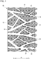
Fig. 1 is a cross-sectional view of a filter cloth according to an embodiment of the present invention. -
Fig. 2 is a flowchart showing a manufacturing procedure of the filter cloth according to the embodiment of the present invention. -
Fig. 3 is a cross-sectional view of a filter cloth substrate during an adsorbent spraying step according to the embodiment of the present invention. -
Fig. 4 is a cross-sectional view of the filter cloth substrate during a catalyst spraying step according to the embodiment of the present invention. -
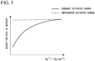
Fig. 5 is a graph showing a relationship between the concentration of bivalent mercury and an adsorption rate of mercury. -
Fig. 6 is a cross-sectional view of a bag filter according to the embodiment of the present invention. -
Fig. 7 is a system diagram of a gas processing apparatus according to the embodiment of the present invention. - Embodiments of a filter cloth, a bag filter including this filter cloth, and a gas processing apparatus according to the present invention will be described with reference to the drawings.
- Hereinafter, an embodiment of the filter cloth according to the present invention will be described with reference to
Figs. 1 to 5 . - As shown in
Fig. 1 , afilter cloth 10 of the present embodiment includes afilter cloth substrate 11 which is formed of a plurality of fibers,particulate adsorbents 17, andparticulate catalysts 16 which promote oxidation of Hg. - The
filter cloth substrate 11 has afirst surface 12 and asecond surface 13. Thefirst surface 12 and thesecond surface 13 face sides opposite to each other. The distance between thefirst surface 12 and thesecond surface 13 is the thickness of thefilter cloth substrate 11. Hereinafter, with respect to a thickness direction Dt of thefilter cloth substrate 11, a side of thesecond surface 13 with respect to thefirst surface 12 is referred to as a downstream side Dd, and a side of thefirst surface 12 with respect to thesecond surface 13 is referred to as an upstream side Du. In thefilter cloth substrate 11, spaces between the plurality of fibers formgas flow channels 14 through which gas (processing target) passes. - Examples of fibers forming the
filter cloth substrate 11 include glass fibers, polyfluoroethylene-based fibers, polyester-based fibers, polyamide-based fibers, and polyphenylene sulfide-based fibers. Fibers having high heat resistance of the foregoing fibers are glass fibers and polyfluoroethylene-based fibers. It is preferable that diameters of the fibers be within a range of 3 to 15 µm. Regarding a method of weaving fibers, any of twill weaving, satin weaving, plain weaving, and the like may be adopted. It is preferable that a thread density of cloth serving as thefilter cloth substrate 11 be within a range of 600 to 1,200 g/m2. If the thread density is equal to or higher than a lower limit, powder in gas can be sufficiently captured, and if it is equal to or lower than an upper limit, clogging can be curbed. - The average particle diameter of the
particulate adsorbents 17 is within a range of 1 µm to 50 µm, for example. Here, theparticulate adsorbents 17 are particulate activated carbon having a function of adsorbing mercury (Hg). As described below, particulate impregnated activated carbon may be used as theparticulate adsorbents 17. Moreover, a mixture of particulate activated carbon and particulate impregnated activated carbon may be used as theparticulate adsorbents 17. Impregnated activated carbon used herein is a substance in which particulate activated carbon is impregnated with a halide. Bromine (Br) is an example of a halide with which activated carbon is impregnated. - An average particle diameter of the
particulate catalysts 16 is within a range of 1 µm to 100 µm, for example. Thecatalysts 16 have carriers and an active component. Regarding the carriers of thecatalysts 16, single oxide or complex oxide including at least one or more elements selected from titanium (Ti), silicon (Si), aluminum (Al), zirconium (Zr), phosphorus (P), and boron (B) is adopted. Regarding the active component of thecatalysts 16, oxide of at least one of vanadium (V), tungsten (W), molybdenum (Mo), niobium (Nb), and tantalum (Ta), or complex oxide of these is adopted. It is preferable to use at least titanium oxide as carriers. It is preferable to use at least vanadium oxide as an active component. All the active components exemplified above have an ability to oxidize various substances including mercury and can also perform oxidative decomposition of dioxin. - The composition of the
catalysts 16 is not particularly limited. When the active component consists of one component such as vanadium pentoxide, it is preferable to have 1 to 20 parts by mass of active substances with respect to 100 parts by mass of carriers. When the active component consists of two components such as vanadium pentoxide and tungsten trioxide, it is preferable to have 1 to 10 parts by mass of vanadium pentoxide and 2 to 25 parts by mass of tungsten trioxide with respect to 100 parts by mass of carriers. - Both the
particulate adsorbents 17 and theparticulate catalysts 16 adhere to onefilter cloth substrate 11. In onefilter cloth substrate 11, a region in which theparticulate adsorbents 17 are distributed does not coincide with a region in which theparticulate catalysts 16 are distributed. - The
particulate catalysts 16 adhere onto thefirst surface 12 of thefilter cloth substrate 11. The adhering amount of theparticulate catalysts 16 on thefirst surface 12 is larger than the adhering amount of theparticulate adsorbents 17 on thefirst surface 12. Here, an adhering amount indicates mass per unit area of an adhesive material. The adhering amount of theparticulate catalysts 16 gradually decreases toward the downstream side Dd from thefirst surface 12 and practically becomes zero in the vicinity of thesecond surface 13. On the other hand, the adhering amount of theparticulate adsorbents 17 gradually decreases after gradually increasing toward the downstream side Dd from thefirst surface 12 and practically becomes zero in the vicinity of thesecond surface 13. Thecatalysts 16 and theadsorbents 17 adhere to inner surfaces of thegas flow channels 14 which are formed in thefilter cloth substrate 11 between thefirst surface 12 and thesecond surface 13. - In other words, in the present embodiment, the ratio of the density of the
catalysts 16 to the density of theadsorbents 17 at a predetermined position on the upstream side Du from thesecond surface 13 is higher than the ratio of the density of thecatalysts 16 to the density of theadsorbents 17 at a part on the downstream side Dd from the predetermined position. In addition, thefilter cloth 10 of the present embodiment has aratio variation region 19 in which the ratio of the density of thecatalysts 16 to the density of theadsorbents 17 gradually decreases toward the downstream side Dd. In the present embodiment, the predetermined position is a position on thefirst surface 12. In addition, in the present embodiment, theadsorbents 17 and thecatalysts 16 do not practically adhere onto thesecond surface 13. The density of an adhesive material indicates mass per unit volume of an adhesive material in thefilter cloth substrate 11. - Next, a method of manufacturing the
filter cloth 10 described above will be described in accordance with the flowchart shown inFig. 2 . - First, one
filter cloth substrate 11, adsorbent slurry containing theadsorbents 17, and catalyst slurry containing thecatalysts 16 are prepared (S1: preparation step). The adsorbent slurry is formed by incorporating theparticulate adsorbents 17 into water. The catalyst slurry is formed by incorporating theparticulate catalysts 16 into water. It is preferable that the concentration of theadsorbents 17 in the adsorbent slurry be lower than the concentration of thecatalysts 16 in the catalyst slurry. Specifically, it is preferable that the concentration of theadsorbents 17 in the adsorbent slurry be within a range of 5 wt% to lower than 15 wt% and the concentration of thecatalysts 16 in the catalyst slurry be 15 wt% or higher. It is more preferable that the concentration of theadsorbents 17 in the adsorbent slurry be within a range of 5 wt% to lower than 12 wt%. - Next, as shown in
Fig. 3 , the adsorbent slurry is sprayed onto thefirst surface 12 toward the downstream side Dd (S2: adsorbent spraying step). As a result, theadsorbents 17 in the adsorbent slurry adhere to thefirst surface 12 of thefilter cloth substrate 11 and the inner surfaces of the plurality ofgas flow channels 14 of thefilter cloth substrate 11. In this adsorbent spraying step (S2), the adhering amount of theparticulate adsorbents 17 can gradually decrease after gradually increasing toward the downstream side Dd from thefirst surface 12 and can practically become zero in the vicinity of thesecond surface 13 by adjusting a spraying pressure and a spraying flow rate of the adsorbent slurry. - Next, as shown in
Fig. 4 , the catalyst slurry is sprayed onto thefirst surface 12 toward the downstream side Dd (S3: catalyst spraying step). As a result, thecatalysts 16 in the catalyst slurry adhere to thefirst surface 12 of thefilter cloth substrate 11 and the inner surfaces of the plurality ofgas flow channels 14 of thefilter cloth substrate 11. However, since theadsorbents 17 which have already adhered to the inner surfaces of the plurality ofgas flow channels 14 of thefilter cloth substrate 11 become obstacles and the concentration of thecatalysts 16 in the catalyst slurry is higher than the concentration of theadsorbents 17 in the adsorbent slurry, it is difficult for thecatalysts 16 to enter an inner side of thegas flow channels 14, that is, the downstream side Dd. For this reason, a large part of thecatalysts 16 in the catalyst slurry adheres to thefirst surface 12 of thefilter cloth substrate 11. In addition, the remainingcatalysts 16 in the catalyst slurry adhere to a part on the upstream side Du on the inner surfaces of the plurality ofgas flow channels 14. - As described above, when the catalyst spraying step (S3) is executed after the adsorbent spraying step (S2) is executed, the distribution of the
particulate adsorbents 17 and the distribution of theparticulate catalysts 16 in onefilter cloth substrate 11 become the distributions described beforehand. - Next, the
filter cloth substrate 11 to which theadsorbents 17 and thecatalysts 16 adhere are dried (S4: drying step). Thefilter cloth 10 of the present embodiment is hereby completed. - During the preparation step (S1), a step of forming catalyst slurry need only be executed before the catalyst spraying step (S3) and need not be executed before the adsorbent spraying step (S2).
- Next, effects of the
filter cloth 10 described above will be described. - The
catalysts 16 have an ability to oxidize substances in gas as described above. For this reason, when zerovalent mercury is included in gas, thecatalysts 16 oxidize this zerovalent mercury to bivalent mercury as shown below.
Hg0→Hg2++2e-
- In ordinary activated carbon which consists of only activated carbon and in which this activated carbon is not impregnated with a halide, as shown in
Fig. 5 , the higher the concentration of bivalent mercury (Hg2+), the higher the adsorption rate of mercury. In contrast, as the concentration of bivalent mercury becomes low and the concentration of zerovalent mercury (Hg0) becomes higher, the adsorption rate of mercury drops. For this reason, in order to raise the adsorption rate of mercury in ordinary activated carbon, it is preferable that this ordinary activated carbon be disposed under an environment of a high concentration of bivalent mercury. - When gas including mercury is caused to flow from the upstream side Du toward the downstream side Dd with respect to the
filter cloth 10 of the present embodiment, a large part of the mercury in this gas becomes bivalent mercury due to a number of thecatalysts 16 which have adhered to thefirst surface 12 of thefilter cloth substrate 11. A large part of the bivalent mercury is bonded to chlorine and the like included in the gas. Thereafter, a large part of bivalent mercury is adsorbed by a large amount of ordinary activated carbon which has adhered in thegas flow channels 14 of thefilter cloth substrate 11. - For instance, it is assumed that the distribution of ordinary activated carbon and the distribution of the
catalysts 16 are substantially uniform in the thickness direction Dt of thefilter cloth substrate 11. In this case, activated carbon positioned at a part on the upstream side Du in thefilter cloth substrate 11 is placed in an environment of a low concentration of bivalent mercury, and thus the adsorption rate of mercury is low. For this reason, in this filter cloth, mercury cannot be efficiently adsorbed. - On the other hand, in the
filter cloth 10 of the present embodiment, a number ofcatalysts 16 adhere to a part of thefilter cloth substrate 11 on the upstream side Du, and a number ofadsorbents 17 including ordinary activated carbon adhere on the downstream side Dd from this position. Therefore, a large amount of ordinary activated carbon is placed in an environment of a high concentration of bivalent mercury. Thus, in thefilter cloth 10 of the present embodiment, mercury can be efficiently adsorbed. In addition, since theadsorbents 17 of the present embodiment include activated carbon, toxic substances such as dioxin can also be adsorbed. - Here, for instance, it is assumed that filter cloths of two kinds are present as follows. A first filter cloth has two filter cloth substrates and is a filter cloth in which the
particulate catalysts 16 adhere to a first filter cloth substrate and theparticulate adsorbents 17 adhere to a second filter cloth substrate. A second filter cloth is a filter cloth in which theadsorbents 17 or thecatalysts 16 are kneaded into fibers constituting the filter cloth substrate. - Since the first filter cloth includes two filter cloth substrates, a pressure loss of gas increases, and the manufacturing cost runs up. On the other hand, the
filter cloth 10 of the present embodiment is constituted of only onefilter cloth substrate 11. For this reason, in thefilter cloth 10 of the present embodiment, compared to the first filter cloth, a pressure loss of gas can be curbed, and a rise in the manufacturing cost can be curbed. - In the second filter cloth, the
adsorbents 17 or thecatalysts 16 are kneaded into fibers constituting the filter cloth substrate. Therefore, the adsorbents or the catalysts are not always present in the gas flow channels in the filter cloth substrate so that a contact ratio between the gas and theadsorbents 17 or thecatalysts 16 is low, and thus the adsorption rate of mercury becomes low. On the other hand, in thefilter cloth 10 of the present embodiment, theadsorbents 17 or thecatalysts 16 adhere to thefirst surface 12 of thefilter cloth substrate 11 or the inner surfaces of thegas flow channels 14 of thefilter cloth substrate 11. For this reason, in thefilter cloth 10 of the present embodiment, compared to the second filter cloth, the contact ratio between the gas and theadsorbents 17 and the contact ratio between the gas and thecatalysts 16 are high, and thus the adsorption rate of mercury can be increased. - A predetermined position in the thickness direction Dt in the
filter cloth substrate 11 of the foregoing embodiment is a position on thefirst surface 12. However, this predetermined position need only be a position on the upstream side Du from thesecond surface 13 and may be a position between thefirst surface 12 and thesecond surface 13. - Regarding a method of manufacturing such a filter cloth, for example, there are two methods as follows. In a first method, the concentration of the
adsorbents 17 in the adsorbent slurry is caused to be lower than that in the foregoing embodiment, and the concentration of thecatalysts 16 in the catalyst slurry is caused to be lower than that in the foregoing embodiment. Moreover, the spraying pressure of the slurry thereof is caused to be higher than that in the foregoing embodiment. In addition, in a second method, first, the catalyst slurry is sprayed onto thesecond surface 13 of thefilter cloth substrate 11 toward the upstream side Du, and then the adsorbent slurry is sprayed onto thesecond surface 13 of thefilter cloth substrate 11 toward the upstream side Du. In this second method, theparticulate catalysts 16 or theparticulate adsorbents 17 adhere to thesecond surface 13. - The
adsorbents 17 of the foregoing embodiment consist of only ordinary activated carbon. However, as described above, particulate impregnated activated carbon may be used or a mixture of particulate activated carbon and particulate impregnated activated carbon may be used as theparticulate adsorbents 17. - In ordinary activated carbon, as described above using
Fig. 5 , the adsorption rate of mercury drops as the concentration of bivalent mercury drops. On the other hand, in impregnated activated carbon in which ordinary activated carbon is impregnated with a halide, as shown inFig. 5 , even if the concentration of bivalent mercury varies, there is a slight variation in the adsorption rate of mercury. Further, this adsorption rate substantially coincides with the adsorption rate of ordinary activated carbon at the time when the concentration of bivalent mercury is 100 wt%. In addition, in ordinary activated carbon, due to a relationship in which the adsorption rate varies in accordance with the concentration of mercury, a part of mercury adsorbed at the time of a high concentration of mercury is sometimes released when the concentration of mercury becomes low. On the other hand, in impregnated activated carbon which has once adsorbed mercury, this mercury is not released unless special processing is performed. - For this reason, regardless of the concentration of bivalent mercury, mercury is stably adsorbed, and when it is desired that adsorbed mercury be prevented from being released, only particulate impregnated activated carbon or a mixture of particulate activated carbon having a high mixing proportion of particulate impregnated activated carbon may be used as the
adsorbents 17. In contrast, when sudden increase of the concentration of mercury temporarily occurs a number of times, in order to extend the usage period of theadsorbents 17, only particulate activated carbon or a mixture of particulate activated carbon having a low mixing proportion of particulate impregnated activated carbon may be used. - Hereinafter, the bag filter of the present embodiment will be described with reference to
Fig. 6 . - A
bag filter 20 of the present embodiment includes a plurality offilters 21 formed of the filter cloth of the embodiment or the modification example thereof described above, abag filter case 22 accommodating the plurality offilters 21, afilter support member 24, and adischarger 25. - The filter cloth of the embodiment or the modification example thereof described above is sewed to have a bag shape and forms the
filters 21. Thefirst surface 12 of thefilter cloth substrate 11 constitutes outer surfaces 21o of the bag-shapedfilters 21, and thesecond surface 13 of thefilter cloth substrate 11 constitutesinner surfaces 21i of the bag-shapedfilters 21. - The
bag filter case 22 has aninlet 22i through which gas flows in to the inside and an outlet 22o through which gas flows out from the inside. Theinlet 22i is formed in afirst side plate 22a of thebag filter case 22, and the outlet 22o is formed in asecond side plate 22b of thebag filter case 22. Thedischarger 25 is connected to a lower portion of thebag filter case 22. For example, thisdischarger 25 is a rotary valve and discharges powder such as dust staying inside thebag filter case 22 to the outside. - The
filter support member 24 is disposed inside thebag filter case 22 and supports the plurality of bag-shapedfilters 21. - The inside of the
bag filter case 22 is partitioned into aspace 23i on the inlet side and a space 23o on the outlet side by the plurality of bag-shapedfilters 21 and thefilter support member 24. The outer surfaces 21o of the bag-shapedfilters 21 supported by thefilter support member 24 face thespace 23i on the inlet side, and theinner surfaces 21i of thefilters 21 face the space 23o on the outlet side. Thus, thefirst surface 12 of thefilter cloth substrate 11 forming thefilters 21 faces thespace 23i on the inlet side, and thesecond surface 13 of thefilter cloth substrate 11 faces the space 23o on the outlet side. - In the
bag filter 20 of the present embodiment, powder such as dust included in gas flowing in from theinlet 22i is captured by thefilters 21, and this powder can be discharged to the outside from thedischarger 25. Moreover, since thebag filter 20 of the present embodiment includes thefilters 21 formed of the filter cloth of the embodiment or the modification example thereof described above, mercury in gas can be efficiently removed using this filter cloth. Gas which has passed through thefilters 21 is discharged to the outside through the outlet 22o. - Hereinafter, the gas processing apparatus of the present embodiment will be described with reference to
Fig. 7 . - The gas processing apparatus of the present embodiment includes the
bag filter 20 of the embodiment described above, a plurality ofpipes adsorbent feeding device 34, agas cooler 35, and ablower 36. - The
pipes side pipe 32 and a downstream-side pipe 33. The upstream-side pipe 32 connects agas generation source 31 such as a garbage incinerator and theinlet 22i of thebag filter 20 to each other. The downstream-side pipe 33 connects the outlet 22o of thebag filter 20 and asmokestack 37 to each other. Theblower 36 is provided in the downstream-side pipe 33, suctions gas inside thebag filter 20, and sends this gas to thesmokestack 37. - The
adsorbent feeding device 34 is connected to the upstream-side pipe 32. Thisadsorbent feeding device 34 has atank 34t storing particulate adsorbents and afeeder 34f feeding adsorbents into the upstream-side pipe 32 from thetank 34t. Thisfeeder 34f is a rotary feeder, for example. - The
gas cooler 35 is provided on thegas generation source 31 side from theadsorbent feeding device 34 in the upstream-side pipe 32. This gas cooler 35 reduces the temperature of gas from thegas generation source 31 to a temperature lower than a heatproof temperature of thefilters 21. - When the
gas generation source 31 is a garbage incinerator, sometimes mercury-containing substances, such as a mercury thermometer including mercury, are fed in together with garbage. Such mercury-containing substances are often fed to the garbage incinerator randomly. For this reason, sometimes the concentration of mercury in gas discharged from the garbage incinerator increases in a spike form. That is, the concentration of mercury in gas discharged from the garbage incinerator increases in a very short period of time and decreases in a very short period of time. In addition, toxic substances such as dioxin are often included in gas. - In the gas processing apparatus of the present embodiment, a constant amount of particulate adsorbent is regularly fed into the upstream-
side pipe 32 from theadsorbent feeding device 34. The adsorbents fed into the upstream-side pipe 32 adsorbs dioxin or the like which is included in gas flowing in this upstream-side pipe 32. The adsorbents which have adsorbed dust, dioxin, or the like included in gas flowing in the upstream-side pipe 32 are captured by thefilters 21 inside thebag filter 20. Dust or the adsorbents captured by thesefilters 21 are shaken off from thefilters 21 and then discharged to the outside from thedischarger 25. Thus, theadsorbents 17 of thefilters 21 are barely used for adsorbing mercury, dioxin, or the like. - When the concentration of mercury in gas discharged from the
gas generation source 31 increases in a spiked shape, unless the amount of adsorbents regularly fed into the upstream-side pipe 32 from theadsorbent feeding device 34 is extremely increased, a large amount of mercury cannot be adsorbed by these adsorbents. In the present embodiment, mercury which cannot be adsorbed by the adsorbents from theadsorbent feeding device 34 is adsorbed by theadsorbents 17 of thefilters 21 of thebag filter 20. - As described above, in the present embodiment, while the amount of adsorbents fed from the
adsorbent feeding device 34 is curbed, mercury in gas increasing in a spiked shape can also be removed. - The adsorbents fed from the
adsorbent feeding device 34 may consist of only ordinary activated carbon similar to theadsorbents 17 included in thefilters 21 of thebag filter 20, may consist of only impregnated activated carbon, and may consist of a mixture of ordinary activated carbon and impregnated activated carbon. - In addition, in the foregoing embodiment, a constant amount of particulate adsorbent is regularly fed into the upstream-
side pipe 32 from theadsorbent feeding device 34. However, as shown inFig. 7 , the gas processing apparatus may include aconcentration meter 38 which detects a Hg concentration in gas and a feedingamount control device 39 which controls the amount of theadsorbents 17 fed into the upstream-side pipe 32 from theadsorbent feeding device 34 in accordance with the Hg concentration detected by theconcentration meter 38. When the Hg concentration detected by theconcentration meter 38 exceeds a value set in advance, this feedingamount control device 39 increases the amount of theadsorbents 17 fed from theadsorbent feeding device 34. - The
concentration meter 38 may be provided in the downstream-side pipe 33 or may be provided in the upstream-side pipe 32 or thesmokestack 37. When theconcentration meter 38 is provided in the downstream-side pipe 33, at least a part of gas including mercury has flowed into thebag filter 20 at the time when the Hg concentration detected by thisconcentration meter 38 has increased. For this reason, even if the amount of adsorbents fed to the upstream-side pipe 32 from theadsorbent feeding device 34 is increased after the Hg concentration detected by theconcentration meter 38 has exceeded a value set in advance, these adsorbents can only adsorb only a part of mercury included in gas. On the other hand, when theconcentration meter 38 is provided in the upstream-side pipe 32, gas including mercury is less likely to be flowing inside thebag filter 20 at the time when the Hg concentration detected by thisconcentration meter 38 has increased. For this reason, a large amount of mercury included in gas can be adsorbed using these adsorbents by increasing the amount of adsorbents fed to the upstream-side pipe 32 from theadsorbent feeding device 34 after the Hg concentration detected by theconcentration meter 38 has exceeded a value set in advance. However, if theconcentration meter 38 is provided in the upstream-side pipe 32, there are cases in which a probe of thisconcentration meter 38 is covered by dust or the like so that the concentration of mercury cannot be detected continuously. For this reason, when theconcentration meter 38 is provided in the upstream-side pipe 32, there is a need for the probe of thisconcentration meter 38 to have a structure such that it is not covered by dust or the like or have a structure such that dust or the like can be shaken off even if the probe is covered by dust or the like. - According to the aspects of the present invention, Hg in gas can be efficiently removed.
-
- 10
- Filter cloth
- 11
- Filter cloth substrate
- 12
- First surface
- 13
- Second surface
- 14
- Gas flow channel
- 16
- Catalyst
- 17
- Adsorbent
- 19
- Ratio variation region
- 20
- Bag filter
- 21
- Filter
- 21i
- Inner surface
- 21o
- Outer surface
- 22
- Bag filter case
- 22a
- First side plate
- 22b
- Second side plate
- 22i
- Inlet
- 22o
- Outlet
- 23i
- Space on inlet side
- 23o
- Space on outlet side
- 24
- Filter support member
- 25
- Discharger
- 31
- Gas generation source
- 32
- Upstream-side pipe
- 33
- Downstream-side pipe
- 34
- Adsorbent feeding device
- 34t
- Tank
- 34f
- Feeder
- 35
- Gas cooler
- 36
- Blower
- 37
- Smokestack
- 38
- Concentration meter
- 39
- Feeding amount control device
- Dt
- Thickness direction
- Du
- Upstream side
- Dd
- Downstream side
Claims (12)
- A filter cloth comprising:one filter cloth substrate formed of a plurality of fibers;particulate adsorbents which include activated carbon and have an ability to absorb Hg; andparticulate catalysts which have an ability to promote oxidation of Hg,wherein the one filter cloth substrate has a first surface and a second surface facing sides opposite to each other, andwherein a ratio of a density of the catalysts to a density of the adsorbents at a predetermined position on an upstream side that is the first surface side from the second surface is higher than a ratio of the density of the catalysts to the density of the adsorbents at a part on a downstream side that is the second surface side from the predetermined position.
- The filter cloth according to claim 1 further comprising:
a region in which the ratio of the density of the catalysts to the density of the adsorbents gradually decreases toward the downstream side. - The filter cloth according to claim 1 or 2,
wherein the predetermined position is a position on the first surface. - The filter cloth according to any one of claims 1 to 3,
wherein the adsorbents and the catalysts do not adhere onto the second surface. - The filter cloth according to any one of claims 1 to 4,
wherein the adsorbents include the activated carbon and a halide,
wherein the activated carbon is impregnated with the halide, and
wherein the halide and the activated carbon form particulate impregnated activated carbon. - The filter cloth according to claim 5,
wherein the particulate impregnated activated carbon and the particulate activated carbon are mixed together in the adsorbents. - A bag filter comprising:a filter formed of the filter cloth according to any one of claims 1 to 6; anda bag filter case which internally accommodates the filter,wherein the bag filter case has an inlet through which gas flows in and an outlet through which gas flows out, andwherein the filter partitions an inside of the bag filter case into a space on the inlet side and a space on the outlet side and is disposed such that the first surface of the filter cloth substrate forming the filter faces the space on the inlet side.
- A gas processing apparatus comprising:the bag filter according to claim 7;an upstream-side pipe configured to introduce gas from a gas generation source to the inlet of the bag filter; andan adsorbent feeding device configured to feed particulate adsorbents including activated carbon and having an ability to absorb Hg into the upstream-side pipe.
- The gas processing apparatus according to claim 8 further comprising:a concentration meter configured to detect a Hg concentration in the gas; anda feeding amount control device configured to control an amount of the adsorbents fed into the upstream-side pipe from the adsorbent feeding device in accordance with the Hg concentration detected by the concentration meter.
- The gas processing apparatus according to claim 9 further comprising:a downstream-side pipe connected to the outlet of the bag filter,wherein the concentration meter configured to detect the Hg concentration in gas flowing in the downstream-side pipe.
- A method for producing a filter cloth and executing
a preparation step of preparing one filter cloth substrate formed of a plurality of fibers, adsorbent slurry which contains adsorbents including activated carbon and having an ability to absorb Hg, and catalyst slurry which contains particulate catalysts having an ability to promote oxidation of Hg,
an adsorbent spraying step of spraying the adsorbent slurry onto a first surface, of the first surface and a second surface facing sides opposite to each other in the one filter cloth substrate, toward a downstream side that is a side of the second surface with respect to the first surface, and
a catalyst spraying step of spraying the catalyst slurry onto the first surface toward the downstream side after the adsorbent spraying step. - The method for producing a filter cloth according to claim 11,
wherein a catalyst concentration in the catalyst slurry is higher than an adsorbent concentration in the adsorbent slurry.
Applications Claiming Priority (2)
| Application Number | Priority Date | Filing Date | Title |
|---|---|---|---|
| JP2018047004A JP7064910B2 (en) | 2018-03-14 | 2018-03-14 | Filter cloth, bug filter, and gas treatment equipment equipped with this |
| PCT/JP2019/008370 WO2019176617A1 (en) | 2018-03-14 | 2019-03-04 | Filter cloth, bag filter, gas processing apparatus equipped with same, and method for producing filter cloth |
Publications (1)
| Publication Number | Publication Date |
|---|---|
| EP3766563A1 true EP3766563A1 (en) | 2021-01-20 |
Family
ID=67907645
Family Applications (1)
| Application Number | Title | Priority Date | Filing Date |
|---|---|---|---|
| EP19768293.3A Withdrawn EP3766563A1 (en) | 2018-03-14 | 2019-03-04 | Filter cloth, bag filter, gas processing apparatus equipped with same, and method for producing filter cloth |
Country Status (5)
| Country | Link |
|---|---|
| EP (1) | EP3766563A1 (en) |
| JP (1) | JP7064910B2 (en) |
| CN (1) | CN111867701A (en) |
| SG (1) | SG11202008610RA (en) |
| WO (1) | WO2019176617A1 (en) |
Families Citing this family (4)
| Publication number | Priority date | Publication date | Assignee | Title |
|---|---|---|---|---|
| JP7269865B2 (en) * | 2019-10-21 | 2023-05-09 | 日立造船株式会社 | Exhaust gas treatment device and exhaust gas treatment method |
| JP7829400B2 (en) * | 2022-05-13 | 2026-03-13 | 三菱重工業株式会社 | Exhaust gas treatment system, power generation equipment equipped therewith, and exhaust gas treatment method |
| JP7395044B1 (en) | 2023-04-21 | 2023-12-08 | 三菱重工環境・化学エンジニアリング株式会社 | gas purification filter |
| CN117160141B (en) * | 2023-07-27 | 2026-04-21 | 安徽省太和县众友筛网滤布制造有限公司 | A special filter cloth for leaching and purification in hydrometallurgical processes |
Family Cites Families (17)
| Publication number | Priority date | Publication date | Assignee | Title |
|---|---|---|---|---|
| JPS5437594B2 (en) * | 1974-10-18 | 1979-11-15 | ||
| JPH1066814A (en) * | 1996-08-28 | 1998-03-10 | Babcock Hitachi Kk | Bag filter for treating exhaust gas and its production |
| JP2003126654A (en) * | 2001-10-19 | 2003-05-07 | Sumitomo Heavy Ind Ltd | Flue gas treatment apparatus |
| JP2004148304A (en) * | 2002-10-11 | 2004-05-27 | Osaka Gas Co Ltd | Dioxins removing filter, and method of removing dioxins and device for treating exhaust gas using the filter |
| US20040074391A1 (en) * | 2002-10-16 | 2004-04-22 | Vincent Durante | Filter system |
| JP4029029B2 (en) * | 2002-12-18 | 2008-01-09 | 三井造船株式会社 | Bug filter |
| US20040176246A1 (en) * | 2003-03-05 | 2004-09-09 | 3M Innovative Properties Company | Catalyzing filters and methods of making |
| EP1598111A1 (en) * | 2004-05-15 | 2005-11-23 | Delphi Technologies, Inc. | Catalyst concentration gradient in a catalysed filter |
| JP3839450B2 (en) * | 2004-10-12 | 2006-11-01 | バブコック日立株式会社 | Exhaust gas treatment equipment |
| JP4582475B2 (en) * | 2004-10-26 | 2010-11-17 | 日本フエルト株式会社 | Felt manufacturing method |
| US8202482B2 (en) * | 2006-07-26 | 2012-06-19 | Babcock-Hitachi Kabushiki Kaisha | Apparatus for removing of trace of toxic substance from exhaust gas and method of operating the same |
| JP2012130853A (en) * | 2010-12-21 | 2012-07-12 | Mitsubishi Heavy Ind Ltd | Bag filter, and exhaust gas treatment apparatus |
| CN104428246A (en) * | 2012-07-10 | 2015-03-18 | 美利肯公司 | Activated carbon articles and compositions and process for producing the same |
| US9138684B2 (en) * | 2013-01-03 | 2015-09-22 | Milliken & Company | Filter for removal of heavy metals |
| JP6567463B2 (en) * | 2016-05-31 | 2019-08-28 | 株式会社タクマ | Exhaust gas treatment method |
| JP2018047004A (en) | 2016-09-21 | 2018-03-29 | 株式会社バンダイナムコエンターテインメント | Program and game system |
| CN106975331A (en) * | 2017-04-27 | 2017-07-25 | 北京清新环境技术股份有限公司 | A kind of smoke catalytic absorbing synergic mercury removal device and its method |
-
2018
- 2018-03-14 JP JP2018047004A patent/JP7064910B2/en active Active
-
2019
- 2019-03-04 EP EP19768293.3A patent/EP3766563A1/en not_active Withdrawn
- 2019-03-04 SG SG11202008610RA patent/SG11202008610RA/en unknown
- 2019-03-04 CN CN201980017945.5A patent/CN111867701A/en active Pending
- 2019-03-04 WO PCT/JP2019/008370 patent/WO2019176617A1/en not_active Ceased
Also Published As
| Publication number | Publication date |
|---|---|
| CN111867701A (en) | 2020-10-30 |
| WO2019176617A1 (en) | 2019-09-19 |
| JP2019155295A (en) | 2019-09-19 |
| SG11202008610RA (en) | 2020-10-29 |
| JP7064910B2 (en) | 2022-05-11 |
Similar Documents
| Publication | Publication Date | Title |
|---|---|---|
| CA2908177C (en) | Method for regenerating denitrification catalyst | |
| CN111867701A (en) | Filter cloth, bag filter, gas treatment equipment provided with the same, and manufacturing method of filter cloth | |
| US20040159235A1 (en) | Low pressure drop canister for fixed bed scrubber applications and method of using same | |
| CN100522313C (en) | Method and apparatus for the abatement of toxic gas components from a semiconductor manufacturing process effluent stream | |
| US9610561B2 (en) | Method of making a honeycomb having channels containing a porous adsorbent | |
| KR101948510B1 (en) | Apparatus and methods for treating exhaust gases | |
| CN113828101B (en) | Runoff adsorption vessel with integrated loading device | |
| US7879758B2 (en) | Catalytically active porous element | |
| WO2001021279A1 (en) | Filter elements and filtering methods | |
| DE60042138D1 (en) | Filtering devices for liquids and gases, and manufacturing processes | |
| JP2025169456A (en) | Process vessel entry zone | |
| Wang et al. | Study on V2O5-WO3-TiO2 catalytic filter for de-NO and particle separation | |
| JP2002273123A (en) | Chemical filter | |
| KR101971645B1 (en) | Filter comprising a coating layer of flake-like powders and a preparation method thereof | |
| EP1144109B1 (en) | Broad spectrum filter system for filtering contaminants from air or other gases | |
| JP3506234B2 (en) | Powder material supply device and exhaust gas treatment device | |
| JP6084072B2 (en) | Toxic substance adsorption device | |
| CN101107053A (en) | Waste gas treatment method and device | |
| US7438864B2 (en) | Purifier | |
| US20230101114A1 (en) | Ion Exchange Exoskeleton and Filter Assembly | |
| KR20250003897A (en) | Absorber canister for exhaust gas reduction system | |
| JP6422716B2 (en) | Fluidized bed equipment | |
| JPH1066814A (en) | Bag filter for treating exhaust gas and its production | |
| TW494006B (en) | Harmful gas purifying column and method | |
| CN117771779A (en) | Filter element and cartridge filter |
Legal Events
| Date | Code | Title | Description |
|---|---|---|---|
| STAA | Information on the status of an ep patent application or granted ep patent |
Free format text: STATUS: THE INTERNATIONAL PUBLICATION HAS BEEN MADE |
|
| PUAI | Public reference made under article 153(3) epc to a published international application that has entered the european phase |
Free format text: ORIGINAL CODE: 0009012 |
|
| STAA | Information on the status of an ep patent application or granted ep patent |
Free format text: STATUS: REQUEST FOR EXAMINATION WAS MADE |
|
| 17P | Request for examination filed |
Effective date: 20200908 |
|
| AK | Designated contracting states |
Kind code of ref document: A1 Designated state(s): AL AT BE BG CH CY CZ DE DK EE ES FI FR GB GR HR HU IE IS IT LI LT LU LV MC MK MT NL NO PL PT RO RS SE SI SK SM TR |
|
| AX | Request for extension of the european patent |
Extension state: BA ME |
|
| DAV | Request for validation of the european patent (deleted) | ||
| DAX | Request for extension of the european patent (deleted) | ||
| STAA | Information on the status of an ep patent application or granted ep patent |
Free format text: STATUS: THE APPLICATION HAS BEEN WITHDRAWN |
|
| 18W | Application withdrawn |
Effective date: 20210716 |