EP3766399A1 - Rolling brush and floor sweeping robot - Google Patents
Rolling brush and floor sweeping robot Download PDFInfo
- Publication number
- EP3766399A1 EP3766399A1 EP18914436.3A EP18914436A EP3766399A1 EP 3766399 A1 EP3766399 A1 EP 3766399A1 EP 18914436 A EP18914436 A EP 18914436A EP 3766399 A1 EP3766399 A1 EP 3766399A1
- Authority
- EP
- European Patent Office
- Prior art keywords
- roller
- sub
- brush
- brush body
- mounting
- Prior art date
- Legal status (The legal status is an assumption and is not a legal conclusion. Google has not performed a legal analysis and makes no representation as to the accuracy of the status listed.)
- Granted
Links
Images

Classifications
-
- A—HUMAN NECESSITIES
- A47—FURNITURE; DOMESTIC ARTICLES OR APPLIANCES; COFFEE MILLS; SPICE MILLS; SUCTION CLEANERS IN GENERAL
- A47L—DOMESTIC WASHING OR CLEANING; SUCTION CLEANERS IN GENERAL
- A47L9/00—Details or accessories of suction cleaners, e.g. mechanical means for controlling the suction or for effecting pulsating action; Storing devices specially adapted to suction cleaners or parts thereof; Carrying-vehicles specially adapted for suction cleaners
- A47L9/02—Nozzles
- A47L9/04—Nozzles with driven brushes or agitators
- A47L9/0461—Dust-loosening tools, e.g. agitators, brushes
- A47L9/0466—Rotating tools
- A47L9/0477—Rolls
-
- A—HUMAN NECESSITIES
- A46—BRUSHWARE
- A46B—BRUSHES
- A46B13/00—Brushes with driven brush bodies or carriers
- A46B13/001—Cylindrical or annular brush bodies
- A46B13/005—Cylindrical or annular brush bodies made up of a series of longitudinal strips or segments
-
- A—HUMAN NECESSITIES
- A46—BRUSHWARE
- A46B—BRUSHES
- A46B13/00—Brushes with driven brush bodies or carriers
- A46B13/001—Cylindrical or annular brush bodies
- A46B13/006—Cylindrical or annular brush bodies formed by winding a strip tuft in a helix about the body
-
- A—HUMAN NECESSITIES
- A46—BRUSHWARE
- A46B—BRUSHES
- A46B2200/00—Brushes characterized by their functions, uses or applications
- A46B2200/30—Brushes for cleaning or polishing
-
- A—HUMAN NECESSITIES
- A47—FURNITURE; DOMESTIC ARTICLES OR APPLIANCES; COFFEE MILLS; SPICE MILLS; SUCTION CLEANERS IN GENERAL
- A47L—DOMESTIC WASHING OR CLEANING; SUCTION CLEANERS IN GENERAL
- A47L2201/00—Robotic cleaning machines, i.e. with automatic control of the travelling movement or the cleaning operation
Definitions
- the present disclosure relates to a technical field of household appliances, and more particularly to a brushroll and a robot vacuum cleaner.
- a brushroll mounted to the robot vacuum cleaner rotates along with the robot vacuum cleaner, and dirt on the ground is hurled into a dust suction port by the rotation of the brushroll, such that the dirt can be sucked into the robot vacuum cleaner more effectively.
- plant fibers of the brushroll can remove the stains on the ground, which will improve the cleaning ability.
- the plant fibers of the existing brushroll have high process requirements, and results in high cost and low efficiency.
- Embodiments of the present disclosure provide a brushroll and a robot vacuum cleaner.
- the brushroll according to embodiments of the present disclosure is used in a robot vacuum cleaner.
- the brushroll according to embodiments of the present disclosure includes: a first roller and a second roller, the first roller and the second roller being mirror-symmetrical in an axial direction perpendicular to the brushroll and coaxially arranged, the first roller being provided with a plurality of first mounting grooves spaced apart and arranged along a circumferential direction of the first roller, while the second roller being provided with a plurality of second mounting grooves spaced apart and arranged along a circumferential direction of the second roller; a first brush member inserted in the first mounting groove; and a second brush member inserted in the second mounting groove.
- the first roller and the second roller are mirror-symmetrical, a bottom surface of each first brush member can be inserted in the first mounting groove, and a bottom surface of each second brush member can be inserted in the second mounting groove, whereby the manufacturing cost of the brushroll can be reduced, the installation thereof is facilitated, and the efficiency is high.
- the robot vacuum cleaner includes a cleaner body and a brushroll provided to the cleaner body.
- the brushroll includes: a first roller and a second roller, the first roller and the second roller being mirror-symmetrical in an axial direction perpendicular to the brushroll and coaxially arranged, the first roller being provided with a plurality of first mounting grooves spaced apart and arranged along a circumferential direction of the first roller, while the second roller being provided with a plurality of second mounting grooves spaced apart and arranged along a circumferential direction of the second roller; a first brush member inserted in the first mounting groove; and a second brush member inserted in the second mounting groove.
- the first roller and the second roller are mirror-symmetrical, a bottom surface of each first brush member can be inserted in the first mounting groove, and a bottom surface of each second brush member can be inserted in the second mounting groove, whereby the manufacturing cost of the brushroll can be reduced, the installation thereof is facilitated, and the efficiency is high.
- robot vacuum cleaner 1000 brushroll 100, first roller 10, first mounting groove 12, first snap groove 14, second roller 20, second mounting groove 22, second snap groove 24, first brush member 30, first mounting portion 32, first dedusting portion 34, first sub-brush body 31, second sub-brush body 33, second brush member 40, second mounting portion 42, second dedusting portion 44, third sub-brush body 41, fourth sub-brush body 43, connecting member 50, disc body 52, first snap block 54, second snap block 56, first end cover 60, second end cover 70, motor rotating cover 200, cleaner body 300, side brush 400.
- a structure in which a first feature is "on" or “below” a second feature may include an embodiment in which the first feature is in direct contact with the second feature, and may also include an embodiment in which the first feature and the second feature are not in direct contact with each other, but are contacted via an additional feature formed therebetween.
- a first feature "on,” “above,” or “on top of” a second feature may include an embodiment in which the first feature is right or obliquely “on,” “above,” or “on top of” the second feature, or just means that the first feature is at a height higher than that of the second feature; while a first feature “below,” “under,” or “on bottom of” a second feature may include an embodiment in which the first feature is right or obliquely “below,” “under,” or “on bottom of” the second feature, or just means that the first feature is at a height lower than that of the second feature.
- the brushroll 100 includes a first roller 10 and a second roller 20.
- the first roller 10 and the second roller 20 are mirror-symmetrical in an axial direction perpendicular to the brushroll 100 and coaxially arranged.
- the first roller 10 is provided with a plurality of first mounting grooves 12 spaced apart and arranged along a circumferential direction of the first roller 10.
- the second roller 20 is provided with a plurality of second mounting grooves 22 spaced apart and arranged along a circumferential direction of the second roller 20.
- the brushroll 100 further includes a first brush member 30 and a second brush member 40. The first brush member 30 is inserted in the first mounting groove 12, while the second brush member 40 is inserted in the second mounting groove 22.
- the first roller 10 and the second roller 20 are mirror-symmetrical, a bottom surface of each first brush member 30 can be inserted in the first mounting groove 12, and a bottom surface of each second brush member 40 can be inserted in the second mounting groove 22, in which way the manufacturing cost of the brushroll 100 can be reduced, the installation thereof is facilitated, and the efficiency is high.
- the first roller 10 and the second roller 20 are molded in a split manner.
- the first roller 10 and the second roller 20 have the same shape and size.
- the first roller 10 and the second roller 20 may each have a substantially cylindrical shape.
- the first roller 10 and the second roller 20 can be obtained by being rotated out of the same mold reversely.
- An end of the first roller 10 and an end of the second roller 20 may be connected together by an external element to form one brushroll 100.
- first roller 10 and the second roller 20 are mirrored and coaxially arranged in the axial direction perpendicular to the brushroll 100, that is, respective central axes of the first roller 10 and the second roller 20 are on the same horizontal plane.
- the first roller 10 and the second roller 20 are symmetrical in a left-and-right direction perpendicular to an axial direction of a central axis of the brushroll 100, and the shapes and sizes of the first roller 10 and the second roller 20 are consistent in a mirrored manner.
- the first mounting grooves 12 provided in the first roller 10 can be evenly spaced apart in the circumferential direction, and for instance, a circumferential angular difference between the two adjacent first mounting grooves 12 is 30 degrees, 60 degrees or 90 degrees, which will not be limited herein.
- the second mounting grooves 22 provided in the second roller 20 can be evenly spaced apart in the circumferential direction, and for instance, a circumferential angular difference between the two adjacent second mounting grooves 22 is 30 degrees, 60 degrees or 90 degrees, which will not be limited herein.
- the first brush member 30 and the second brush member 40 are both brush structures for cleaning.
- the first brush member 30 includes a leather strip structure or a fur strip structure having different cleaning capabilities.
- the second brush member 40 also includes a leather strip structure or a fur strip structure having different cleaning capabilities.
- the first brush member 30 is movable relative to the first mounting groove 12, and the second brush member 40 is movable relative to the second mounting groove 22.
- the first brush member 30 can be inserted into the first mounting groove 12 along an axial direction of the first mounting groove 12
- the second brush member 40 can be inserted into the second mounting groove 22 along an axial direction of the second mounting groove 22, which leads to high efficiency, convenient installation, and low cost.
- the plurality of the first mounting grooves 12 are arranged spirally along an axial direction of the first roller 10
- the plurality of the second mounting grooves 22 are arranged spirally along an axial direction of the second roller 20.
- the spiral direction of the first mounting grooves 12 is opposite to the spiral direction of the second mounting grooves 22, such that the cleaning ability of the brushroll 100 can be enhanced.
- the spiral direction of the first mounting grooves 12 is from bottom to top, while the spiral direction of the second mounting grooves 22 is from top to bottom. That is, the spiral direction of the first roller 10 is opposite to the spiral direction of the second roller 20.
- the first brush member 30 includes a first mounting portion 32 and a first dedusting portion 34 provided to the first mounting portion 32.
- the first brush member 30 is inserted in the first mounting groove 12 through the first mounting portion 32.
- the second brush member 40 includes a second mounting portion 42 and a second dedusting portion 44 provided to the second mounting portion 42.
- the second brush member 40 is inserted in the second mounting groove 22 through the second mounting portion 42.
- first brush member 30 can be quickly mounted into the first mounting groove 12 through the first mounting portion 32, and the second brush member 40 can be quickly mounted into the second mounting groove 22 through the second mounting portion 42, which brings about high efficiency and low cost.
- the first dedusting portion 34 can adhere to the first mounting portion 32 by means of an adhesive, and the second dedusting portion 44 can also adhere to the second mounting portion 42 by means of an adhesive.
- the first dedusting portion 34 can be mounted to the first mounting portion 32 by mechanical pressing, and the second dedusting portion 44 can also be mounted to the second mounting portion 42 by mechanical pressing.
- the first brush member 30 includes a first sub-brush body 31 and a second sub-brush body 33, and the first sub-brush body 31 and the second sub-brush body 33 are alternately inserted in the first mounting grooves 12 along the circumferential direction of the first roller 10.
- the first dedusting portion 34 of the first sub-brush body 31 has greater rigidity than the first dedusting portion 34 of the second sub-brush body 33.
- the second brush member 40 includes a third sub-brush body 41 and a fourth sub-brush body 43, and the third sub-brush body 41 and the fourth sub-brush body 43 are alternately inserted in the second mounting grooves 22 along the circumferential direction of the second roller 20.
- the second dedusting portion 44 of the third sub-brush body 41 has greater rigidity than the second dedusting portion 44 of the fourth sub-brush body 43.
- the brushroll 100 can adapt to different types of floor to be cleaned, thereby resulting in good user experience.
- first sub-brush body 31 and the second sub-brush body 33 are alternately inserted in the first mounting grooves 12 along the circumferential direction of the first roller 10.
- first sub-brush body 31 and the second sub-brush body 33 are evenly and alternately inserted in the first mounting grooves 12 along the circumferential direction of the first roller 10. That is, the circumferential angular difference between the adjacent first sub-brush body 31 and the second sub-brush body 33 is consistent.
- the circumferential angular difference between the adjacent first sub-brush body 31 and the second sub-brush body 33 is 60 degrees.
- the third sub-brush body 41 and the fourth sub-brush body 43 are alternately inserted in the second mounting grooves 22 along the circumferential direction of the second roller 20.
- the third sub-brush body 41 and the fourth sub-brush body 43 are evenly and alternately inserted in the second mounting grooves 22 along the circumferential direction of the second roller 20. That is, the circumferential angular difference between the adjacent third sub-brush body 41 and the fourth sub-brush body 43 is consistent.
- the circumferential angular difference between the adjacent third sub-brush body 41 and the fourth sub-brush body 43 is 60 degrees.
- the rigidity of the first dedusting portion 34 of the first sub-brush body 31 is greater than the rigidity of the first dedusting portion 34 of the second sub-brush body 33, that is, the cleaning force of the first dedusting portion 34 of the first sub-brush body 31 is greater than the cleaning force of the first dedusting portion 34 of the second sub-brush body 33.
- the different rigidity of the first sub-brush body 31 and the second sub-brush body 33 enables the brushroll 100 to adapt to different floor types during the cleaning.
- the rigidity of the second dedusting portion 44 of the third sub-brush body 41 is greater than the rigidity of the second dedusting portion 44 of the fourth sub-brush body 43, that is, the cleaning force of the second dedusting portion 44 of the third sub-brush body 41 is greater than the cleaning force of the second dedusting portion 44 of the fourth sub-brush body 43.
- the different rigidity of the third sub-brush body 41 and the fourth sub-brush body 43 enables the brushroll 100 to adapt to different floor types during the cleaning.
- the first sub-brush body 31 can be a leather strip for cleaning, and the integral leather strip can be directly mounted to the first mounting portion 32.
- the second sub-brush body 33 can be a fur strip for cleaning, and the fur strip is mounted to the first mounting portion 32.
- the third sub-brush body 41 can be a leather strip for cleaning, and the whole leather strip can be directly mounted to the second mounting portion 42.
- the fourth sub-brush body 43 can be a fur strip for cleaning, and the fur strip is mounted to the second mounting portion 42.
- three first sub-brush bodies 31 and three second sub-brush bodies 33 are provided, and meanwhile, three third sub-brush bodies 41 and three fourth sub-brush bodies 43 are provided.
- three first sub-brush bodies 31 and three second sub-brush bodies 33 are provided.
- three third sub-brush bodies 41 and three fourth sub-brush bodies 43 are provided.
- the brushroll 100 can have an improved cleaning ability, a simple structure, and low costs.
- a circumferential angular different between adjacent two second sub-brush bodies 33 is 120 degrees; a circumferential angular different between adjacent two third sub-brush bodies 41 is 120 degrees; a circumferential angular different between adjacent two fourth sub-brush bodies 43 is 120 degrees.
- an end of the second sub-brush body 33 away from the first roller 10 is higher than an end of the first sub-brush body 31 away from the first roller 10, and meanwhile, an end of the third sub-brush body 41 away from the second roller 20 is higher than an end of the fourth sub-brush body 43 away from the second roller 20.
- an end of the second sub-brush body 33 away from the first roller 10 is higher than an end of the first sub-brush body 31 away from the first roller 10.
- an end of the third sub-brush body 41 away from the second roller 20 is higher than an end of the fourth sub-brush body 43 away from the second roller 20.
- the cleaning ability of the brushroll 100 can be improved, and the brushroll 100 can adapt to different floor types during the cleaning.
- the height of the second sub-brush body 33 is higher than the height of the first sub-brush body 31 by 0.4 mm.
- the height of the fourth sub-brush body 43 is higher than the height of the third sub-brush body 41 by 0.4 mm.
- the height difference between the first sub-brush body 31 and the second sub-brush body 33 can be determined based on actual requirements, which will not be limited herein.
- the height difference between the third sub-brush body 41 and the fourth sub-brush body 43 can be determined based on actual requirements, which will not be limited herein.
- the first mounting groove 12 is a T-shaped groove
- the second mounting groove 22 is a T-shaped groove, such that the first brush member 30 can be easily inserted in the first mounting groove 12, and the second brush member 40 can be easily inserted in the second mounting groove 22.
- the brushroll 100 includes a connecting member 50 that connects the first roller 10 and the second roller 20, and the connecting member 50 is used to limit relative rotation of the first roller 10 and the second roller 20.
- the connecting member 50 is used to limit relative rotation of the first roller 10 and the second roller 20.
- the connecting member 50 may be a separate component, and two ends of the connecting member 50 are connected to the first roller 10 and the second roller 20, respectively.
- the diameter of the connecting member 50 can be consistent with the diameter of the first roller 10 and the diameter of the second roller 20.
- the connecting member 50 may exhibit a circular ring shape.
- the connecting member 50 includes a disc body 52, a first snap block 54, and a second snap block 56.
- the first snap block 54 and the second snap block 56 are provided to two opposite sides of the disc body 52.
- the first roller 10 is provided with a first snap groove 14, and the second roller 20 is provided with a second snap groove 24.
- the first snap block 54 is snap-fitted in the first snap groove 14, and the second snap block 56 is snap-fitted in the second snap groove 24.
- first roller 10 and the second roller 20 can be easily secured together through the fitting between the first snap block 54 and the first snap groove 14 and the fitting between the second snap block 56 and the second snap groove 24.
- first snap blocks 54 are provided and evenly spaced
- second snap blocks 56 are provided and evenly spaced.
- the numbers of the first snap blocks 54 and the second snap blocks 56 are not limited herein, and can be determined based on actual requirements.
- an end of the first roller 10 is provided with the first snap groove 14 away from the second roller 20, that is, the first snap groove 14 can be perpendicular to a sectional direction of the disc body 52.
- An end of the second roller 20 is provided with the second snap groove 24 away from the first roller 10, that is, the second snap groove 24 can be perpendicular to the sectional direction of the disc body 52.
- inventions of the present disclosure also provide a robot vacuum cleaner 1000.
- the robot vacuum cleaner 1000 includes the brushroll 100 according to any one of the above embodiments.
- the brushroll 100 is mounted to a cleaner body 300.
- the cleaner body 300 includes a motor (not illustrated), and the motor is used to drive the brushroll 100 to rotate.
- the first roller 10 and the second roller 20 are mirror-symmetrical, the bottom surface of each first brush member 30 can be inserted in the first mounting groove 12, and the bottom surface of each second brush member 40 can be inserted in the second mounting groove 22, whereby the manufacturing cost of the brushroll 100 can be reduced, the installation thereof is facilitated, and the efficiency is high.
- the robot vacuum cleaner 1000 further includes a motor rotating cover 200, the motor rotating cover 200 is connected with the motor, and the motor rotating cover 200 can be driven to rotate when the motor rotates.
- the brushroll 100 further includes a first end cover 60 and a second end cover 70, the first end cover 60 is connected with the motor rotating cover 200 and the first roller 10, and the second end cover 70 is connected with the second roller 20.
- the robot vacuum cleaner 1000 further includes a side brush 400 (not illustrated).
- the cleaner body 300 may be formed in a circular or substantially square shape, and the cleaner body 300 may be a plastic cleaner body.
- a front side of the cleaner body 300 can be provided with a bumper (not illustrated), and a spring can be provided between the bumper and the cleaner body 300, such that the spring can buffer a collision force exerted on the robot vacuum cleaner 1000 after the cleaner body 300 collides with any barriers.
- a dust cup (not illustrated) can be provided in the cleaner body 300 and have at least one layer of filtration structure.
- a dust suction port (not illustrated) is provided in a bottom surface of the cleaner body 300, and can be in communication with the dust cup.
- a vacuum motor for generating a negative pressure can be arranged at a rear side of the dust cup, and under the action of the vacuum motor, dust can be sucked into the dust cup from the dust suction port. After a user uses the robot vacuum cleaner 1000 for a certain period of time, the dust cup can be taken out from the cleaner body 300 of the robot vacuum cleaner 1000, and the dust can be dumped. Meanwhile, the user can also regularly clean the dust cup and the filtration structure.
- a wheel (not illustrated) can be provided at each of two sides of the dust cup, and each wheel can be driven by a separate drive motor (not illustrated).
- a separate drive motor (not illustrated).
- an omni-directional wheel having support and steering functions can also be provided.
- the present disclosure is not limited thereto.
- the side brush 400 can be provided to a bottom of the cleaner body 300 and located at a front side of the two wheels.
- the side brush 400 can be driven by a separate motor.
- the side brush 400 can collect dust at the bottom of the cleaner body 300 and the sides of the cleaner body 300 to the dust suction port, so that the dust can be sucked into the dust cup more efficiently.
- first and second are used herein for purposes of description and are not intended to indicate or imply relative importance or significance or to imply the number of indicated technical features.
- the feature defined with “first” and “second” may comprise one or more of this feature.
- a plurality of means two or more than two, unless specified otherwise.
Landscapes
- Engineering & Computer Science (AREA)
- Mechanical Engineering (AREA)
- Nozzles For Electric Vacuum Cleaners (AREA)
- Cleaning In General (AREA)
- Electric Vacuum Cleaner (AREA)
Abstract
Description
- This application claims priority to and the benefit of Chinese Patent Application No.
201820497196.3 - The present disclosure relates to a technical field of household appliances, and more particularly to a brushroll and a robot vacuum cleaner.
- In the related art, when a robot vacuum cleaner operates, a brushroll mounted to the robot vacuum cleaner rotates along with the robot vacuum cleaner, and dirt on the ground is hurled into a dust suction port by the rotation of the brushroll, such that the dirt can be sucked into the robot vacuum cleaner more effectively. Moreover, plant fibers of the brushroll can remove the stains on the ground, which will improve the cleaning ability. However, the plant fibers of the existing brushroll have high process requirements, and results in high cost and low efficiency.
- Embodiments of the present disclosure provide a brushroll and a robot vacuum cleaner.
- The brushroll according to embodiments of the present disclosure is used in a robot vacuum cleaner. The brushroll according to embodiments of the present disclosure includes: a first roller and a second roller, the first roller and the second roller being mirror-symmetrical in an axial direction perpendicular to the brushroll and coaxially arranged, the first roller being provided with a plurality of first mounting grooves spaced apart and arranged along a circumferential direction of the first roller, while the second roller being provided with a plurality of second mounting grooves spaced apart and arranged along a circumferential direction of the second roller; a first brush member inserted in the first mounting groove; and a second brush member inserted in the second mounting groove.
- In the brushroll according to embodiments of the present disclosure, the first roller and the second roller are mirror-symmetrical, a bottom surface of each first brush member can be inserted in the first mounting groove, and a bottom surface of each second brush member can be inserted in the second mounting groove, whereby the manufacturing cost of the brushroll can be reduced, the installation thereof is facilitated, and the efficiency is high.
- The robot vacuum cleaner according to embodiments of the present disclosure includes a cleaner body and a brushroll provided to the cleaner body. The brushroll includes: a first roller and a second roller, the first roller and the second roller being mirror-symmetrical in an axial direction perpendicular to the brushroll and coaxially arranged, the first roller being provided with a plurality of first mounting grooves spaced apart and arranged along a circumferential direction of the first roller, while the second roller being provided with a plurality of second mounting grooves spaced apart and arranged along a circumferential direction of the second roller; a first brush member inserted in the first mounting groove; and a second brush member inserted in the second mounting groove.
- In the robot vacuum cleaner according to embodiments of the present disclosure, the first roller and the second roller are mirror-symmetrical, a bottom surface of each first brush member can be inserted in the first mounting groove, and a bottom surface of each second brush member can be inserted in the second mounting groove, whereby the manufacturing cost of the brushroll can be reduced, the installation thereof is facilitated, and the efficiency is high.
- Additional aspects and advantages of embodiments of present disclosure will be given in part in the following descriptions, become apparent in part from the following descriptions, or be learned from the practice of the embodiments of the present disclosure.
- These and/or other aspects and advantages of the present disclosure will become apparent and more readily appreciated from the following descriptions of embodiments made with reference to the drawings, in which:
-
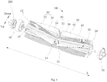
Fig. 1 is a schematic view of a brushroll according to an embodiment of the present disclosure. -
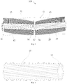
Fig. 2 is another schematic view of a brushroll according to an embodiment of the present disclosure. -
Fig. 3 is a schematic view of a first roller according to an embodiment of the present disclosure. -
Fig. 4 is a schematic view of a first sub-brush body according to an embodiment of the present disclosure. -
Fig. 5 is a schematic view of a second sub-brush body according to an embodiment of the present disclosure. -
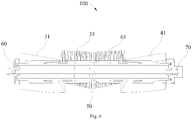
Fig. 6 is a sectional view of a brushroll according to an embodiment of the present disclosure. -
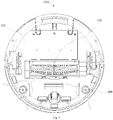
Fig. 7 is a bottom view of a robot vacuum cleaner according to an embodiment of the present disclosure. -
robot vacuum cleaner 1000,brushroll 100,first roller 10,first mounting groove 12,first snap groove 14,second roller 20, second mounting groove 22,second snap groove 24,first brush member 30,first mounting portion 32,first dedusting portion 34,first sub-brush body 31,second sub-brush body 33,second brush member 40,second mounting portion 42,second dedusting portion 44,third sub-brush body 41,fourth sub-brush body 43, connectingmember 50,disc body 52,first snap block 54,second snap block 56,first end cover 60,second end cover 70,motor rotating cover 200,cleaner body 300,side brush 400. - Further illustration of embodiments of the present disclosure will be made with reference to the drawings. The same or similar elements and the elements having same or similar functions are denoted by like reference numerals throughout the descriptions.
- In addition, the embodiments described herein with reference to drawings are illustrative, and used to generally understand the present disclosure. The embodiments shall not be construed to limit the present disclosure.
- In the present disclosure, unless specified or limited otherwise, a structure in which a first feature is "on" or "below" a second feature may include an embodiment in which the first feature is in direct contact with the second feature, and may also include an embodiment in which the first feature and the second feature are not in direct contact with each other, but are contacted via an additional feature formed therebetween. Furthermore, a first feature "on," "above," or "on top of" a second feature may include an embodiment in which the first feature is right or obliquely "on," "above," or "on top of" the second feature, or just means that the first feature is at a height higher than that of the second feature; while a first feature "below," "under," or "on bottom of" a second feature may include an embodiment in which the first feature is right or obliquely "below," "under," or "on bottom of" the second feature, or just means that the first feature is at a height lower than that of the second feature.
- Referring to
Figs. 1 and2 , abrushroll 100 is provided in the present disclosure. Thebrushroll 100 includes afirst roller 10 and asecond roller 20. Thefirst roller 10 and thesecond roller 20 are mirror-symmetrical in an axial direction perpendicular to thebrushroll 100 and coaxially arranged. Thefirst roller 10 is provided with a plurality offirst mounting grooves 12 spaced apart and arranged along a circumferential direction of thefirst roller 10. Thesecond roller 20 is provided with a plurality of second mounting grooves 22 spaced apart and arranged along a circumferential direction of thesecond roller 20. Thebrushroll 100 further includes afirst brush member 30 and asecond brush member 40. Thefirst brush member 30 is inserted in thefirst mounting groove 12, while thesecond brush member 40 is inserted in the second mounting groove 22. - In the
brushroll 100 according to the above embodiment, thefirst roller 10 and thesecond roller 20 are mirror-symmetrical, a bottom surface of eachfirst brush member 30 can be inserted in thefirst mounting groove 12, and a bottom surface of eachsecond brush member 40 can be inserted in the second mounting groove 22, in which way the manufacturing cost of thebrushroll 100 can be reduced, the installation thereof is facilitated, and the efficiency is high. - Specifically, the
first roller 10 and thesecond roller 20 are molded in a split manner. Thefirst roller 10 and thesecond roller 20 have the same shape and size. Thefirst roller 10 and thesecond roller 20 may each have a substantially cylindrical shape. When thebrushroll 100 is produced using a mold for thebrushroll 100, thefirst roller 10 and thesecond roller 20 can be obtained by being rotated out of the same mold reversely. An end of thefirst roller 10 and an end of thesecond roller 20 may be connected together by an external element to form onebrushroll 100. - It could be understood that the
first roller 10 and thesecond roller 20 are mirrored and coaxially arranged in the axial direction perpendicular to thebrushroll 100, that is, respective central axes of thefirst roller 10 and thesecond roller 20 are on the same horizontal plane. Thefirst roller 10 and thesecond roller 20 are symmetrical in a left-and-right direction perpendicular to an axial direction of a central axis of thebrushroll 100, and the shapes and sizes of thefirst roller 10 and thesecond roller 20 are consistent in a mirrored manner. - Specifically, in one example, the
first mounting grooves 12 provided in thefirst roller 10 can be evenly spaced apart in the circumferential direction, and for instance, a circumferential angular difference between the two adjacentfirst mounting grooves 12 is 30 degrees, 60 degrees or 90 degrees, which will not be limited herein. The second mounting grooves 22 provided in thesecond roller 20 can be evenly spaced apart in the circumferential direction, and for instance, a circumferential angular difference between the two adjacent second mounting grooves 22 is 30 degrees, 60 degrees or 90 degrees, which will not be limited herein. - The
first brush member 30 and thesecond brush member 40 are both brush structures for cleaning. In one embodiment, thefirst brush member 30 includes a leather strip structure or a fur strip structure having different cleaning capabilities. Thesecond brush member 40 also includes a leather strip structure or a fur strip structure having different cleaning capabilities. Thefirst brush member 30 is movable relative to thefirst mounting groove 12, and thesecond brush member 40 is movable relative to the second mounting groove 22. During the production and assembly, thefirst brush member 30 can be inserted into thefirst mounting groove 12 along an axial direction of thefirst mounting groove 12, and thesecond brush member 40 can be inserted into the second mounting groove 22 along an axial direction of the second mounting groove 22, which leads to high efficiency, convenient installation, and low cost. - Referring to
Figs. 1 and3 , in certain embodiments, the plurality of thefirst mounting grooves 12 are arranged spirally along an axial direction of thefirst roller 10, and the plurality of the second mounting grooves 22 are arranged spirally along an axial direction of thesecond roller 20. Along the axial direction of thefirst roller 10, the spiral direction of thefirst mounting grooves 12 is opposite to the spiral direction of the second mounting grooves 22, such that the cleaning ability of thebrushroll 100 can be enhanced. - It could be understood that in the axial direction L of the
first roller 10 from left to right, the spiral direction of thefirst mounting grooves 12 is from bottom to top, while the spiral direction of the second mounting grooves 22 is from top to bottom. That is, the spiral direction of thefirst roller 10 is opposite to the spiral direction of thesecond roller 20. In addition, during the production of thefirst roller 10 and thesecond roller 20, it is only necessary to rotate blanks of thefirst roller 10 and thesecond roller 20 in different directions to obtain mounting grooves having the opposite spiral directions, so as to obtain thefirst roller 10 and thesecond roller 20. - Referring to
Figs. 1 ,4 and 5 , in certain embodiments, thefirst brush member 30 includes afirst mounting portion 32 and afirst dedusting portion 34 provided to thefirst mounting portion 32. Thefirst brush member 30 is inserted in thefirst mounting groove 12 through thefirst mounting portion 32. Thesecond brush member 40 includes asecond mounting portion 42 and asecond dedusting portion 44 provided to thesecond mounting portion 42. Thesecond brush member 40 is inserted in the second mounting groove 22 through the second mountingportion 42. - Thus, the
first brush member 30 can be quickly mounted into the first mountinggroove 12 through the first mountingportion 32, and thesecond brush member 40 can be quickly mounted into the second mounting groove 22 through the second mountingportion 42, which brings about high efficiency and low cost. - Specifically, in one embodiment, the
first dedusting portion 34 can adhere to the first mountingportion 32 by means of an adhesive, and thesecond dedusting portion 44 can also adhere to the second mountingportion 42 by means of an adhesive. In another embodiment, thefirst dedusting portion 34 can be mounted to the first mountingportion 32 by mechanical pressing, and thesecond dedusting portion 44 can also be mounted to the second mountingportion 42 by mechanical pressing. - Referring to
Fig. 1 , in certain embodiments, thefirst brush member 30 includes a firstsub-brush body 31 and a secondsub-brush body 33, and the firstsub-brush body 31 and the secondsub-brush body 33 are alternately inserted in the first mountinggrooves 12 along the circumferential direction of thefirst roller 10. Thefirst dedusting portion 34 of the firstsub-brush body 31 has greater rigidity than thefirst dedusting portion 34 of the secondsub-brush body 33. Thesecond brush member 40 includes a thirdsub-brush body 41 and a fourthsub-brush body 43, and the thirdsub-brush body 41 and the fourthsub-brush body 43 are alternately inserted in the second mounting grooves 22 along the circumferential direction of thesecond roller 20. Thesecond dedusting portion 44 of the thirdsub-brush body 41 has greater rigidity than thesecond dedusting portion 44 of the fourthsub-brush body 43. - Thus, the
brushroll 100 can adapt to different types of floor to be cleaned, thereby resulting in good user experience. - It could be understood that the first
sub-brush body 31 and the secondsub-brush body 33 are alternately inserted in the first mountinggrooves 12 along the circumferential direction of thefirst roller 10. In one embodiment, the firstsub-brush body 31 and the secondsub-brush body 33 are evenly and alternately inserted in the first mountinggrooves 12 along the circumferential direction of thefirst roller 10. That is, the circumferential angular difference between the adjacent firstsub-brush body 31 and the secondsub-brush body 33 is consistent. Preferably, the circumferential angular difference between the adjacent firstsub-brush body 31 and the secondsub-brush body 33 is 60 degrees. Likewise, the thirdsub-brush body 41 and the fourthsub-brush body 43 are alternately inserted in the second mounting grooves 22 along the circumferential direction of thesecond roller 20. In one embodiment, the thirdsub-brush body 41 and the fourthsub-brush body 43 are evenly and alternately inserted in the second mounting grooves 22 along the circumferential direction of thesecond roller 20. That is, the circumferential angular difference between the adjacent thirdsub-brush body 41 and the fourthsub-brush body 43 is consistent. Preferably, the circumferential angular difference between the adjacent thirdsub-brush body 41 and the fourthsub-brush body 43 is 60 degrees. - Further, the rigidity of the
first dedusting portion 34 of the firstsub-brush body 31 is greater than the rigidity of thefirst dedusting portion 34 of the secondsub-brush body 33, that is, the cleaning force of thefirst dedusting portion 34 of the firstsub-brush body 31 is greater than the cleaning force of thefirst dedusting portion 34 of the secondsub-brush body 33. The different rigidity of the firstsub-brush body 31 and the secondsub-brush body 33 enables thebrushroll 100 to adapt to different floor types during the cleaning. Likewise, the rigidity of thesecond dedusting portion 44 of the thirdsub-brush body 41 is greater than the rigidity of thesecond dedusting portion 44 of the fourthsub-brush body 43, that is, the cleaning force of thesecond dedusting portion 44 of the thirdsub-brush body 41 is greater than the cleaning force of thesecond dedusting portion 44 of the fourthsub-brush body 43. The different rigidity of the thirdsub-brush body 41 and the fourthsub-brush body 43 enables thebrushroll 100 to adapt to different floor types during the cleaning. - Specifically, the first
sub-brush body 31 can be a leather strip for cleaning, and the integral leather strip can be directly mounted to the first mountingportion 32. The secondsub-brush body 33 can be a fur strip for cleaning, and the fur strip is mounted to the first mountingportion 32. The thirdsub-brush body 41 can be a leather strip for cleaning, and the whole leather strip can be directly mounted to the second mountingportion 42. The fourthsub-brush body 43 can be a fur strip for cleaning, and the fur strip is mounted to the second mountingportion 42. - In one embodiment, three first
sub-brush bodies 31 and three secondsub-brush bodies 33 are provided, and meanwhile, three thirdsub-brush bodies 41 and three fourthsub-brush bodies 43 are provided. In another embodiment, three firstsub-brush bodies 31 and three secondsub-brush bodies 33 are provided. In yet another embodiment, three thirdsub-brush bodies 41 and three fourthsub-brush bodies 43 are provided. - Thus, the
brushroll 100 can have an improved cleaning ability, a simple structure, and low costs. - It could be understood that a circumferential angular different between adjacent two second
sub-brush bodies 33 is 120 degrees; a circumferential angular different between adjacent two thirdsub-brush bodies 41 is 120 degrees; a circumferential angular different between adjacent two fourthsub-brush bodies 43 is 120 degrees. - In one embodiment, an end of the second
sub-brush body 33 away from thefirst roller 10 is higher than an end of the firstsub-brush body 31 away from thefirst roller 10, and meanwhile, an end of the thirdsub-brush body 41 away from thesecond roller 20 is higher than an end of the fourthsub-brush body 43 away from thesecond roller 20. In another embodiment, an end of the secondsub-brush body 33 away from thefirst roller 10 is higher than an end of the firstsub-brush body 31 away from thefirst roller 10. In yet another embodiment, an end of the thirdsub-brush body 41 away from thesecond roller 20 is higher than an end of the fourthsub-brush body 43 away from thesecond roller 20. - Thus, the cleaning ability of the
brushroll 100 can be improved, and thebrushroll 100 can adapt to different floor types during the cleaning. - Preferably, the height of the second
sub-brush body 33 is higher than the height of the firstsub-brush body 31 by 0.4 mm. The height of the fourthsub-brush body 43 is higher than the height of the thirdsub-brush body 41 by 0.4 mm. Certainly, the height difference between the firstsub-brush body 31 and the secondsub-brush body 33 can be determined based on actual requirements, which will not be limited herein. Likewise, the height difference between the thirdsub-brush body 41 and the fourthsub-brush body 43 can be determined based on actual requirements, which will not be limited herein. - Referring to
Figs. 1 and3 , in certain embodiments, the first mountinggroove 12 is a T-shaped groove, and the second mounting groove 22 is a T-shaped groove, such that thefirst brush member 30 can be easily inserted in the first mountinggroove 12, and thesecond brush member 40 can be easily inserted in the second mounting groove 22. - Referring to
Figs. 1 and2 , in certain embodiments, thebrushroll 100 includes a connectingmember 50 that connects thefirst roller 10 and thesecond roller 20, and the connectingmember 50 is used to limit relative rotation of thefirst roller 10 and thesecond roller 20. Thus, the interconnection between thefirst roller 10 and thesecond roller 20 can be achieved through the connectingmember 50, which makes the structure simple. - Specifically, the connecting
member 50 may be a separate component, and two ends of the connectingmember 50 are connected to thefirst roller 10 and thesecond roller 20, respectively. The diameter of the connectingmember 50 can be consistent with the diameter of thefirst roller 10 and the diameter of thesecond roller 20. In one embodiment, the connectingmember 50 may exhibit a circular ring shape. - Referring to
Figs. 1 and2 , in certain embodiments, the connectingmember 50 includes adisc body 52, afirst snap block 54, and asecond snap block 56. Thefirst snap block 54 and thesecond snap block 56 are provided to two opposite sides of thedisc body 52. Thefirst roller 10 is provided with afirst snap groove 14, and thesecond roller 20 is provided with asecond snap groove 24. Thefirst snap block 54 is snap-fitted in thefirst snap groove 14, and thesecond snap block 56 is snap-fitted in thesecond snap groove 24. - Thus, the
first roller 10 and thesecond roller 20 can be easily secured together through the fitting between thefirst snap block 54 and thefirst snap groove 14 and the fitting between thesecond snap block 56 and thesecond snap groove 24. - Specifically, a plurality of first snap blocks 54 are provided and evenly spaced, and a plurality of second snap blocks 56 are provided and evenly spaced. The numbers of the first snap blocks 54 and the second snap blocks 56 are not limited herein, and can be determined based on actual requirements.
- It could be understood that an end of the
first roller 10 is provided with thefirst snap groove 14 away from thesecond roller 20, that is, thefirst snap groove 14 can be perpendicular to a sectional direction of thedisc body 52. An end of thesecond roller 20 is provided with thesecond snap groove 24 away from thefirst roller 10, that is, thesecond snap groove 24 can be perpendicular to the sectional direction of thedisc body 52. - Referring to
Fig. 7 , embodiments of the present disclosure also provide arobot vacuum cleaner 1000. Therobot vacuum cleaner 1000 includes thebrushroll 100 according to any one of the above embodiments. Thebrushroll 100 is mounted to acleaner body 300. Thecleaner body 300 includes a motor (not illustrated), and the motor is used to drive thebrushroll 100 to rotate. - In the
robot vacuum cleaner 1000 according to the above embodiments, thefirst roller 10 and thesecond roller 20 are mirror-symmetrical, the bottom surface of eachfirst brush member 30 can be inserted in the first mountinggroove 12, and the bottom surface of eachsecond brush member 40 can be inserted in the second mounting groove 22, whereby the manufacturing cost of thebrushroll 100 can be reduced, the installation thereof is facilitated, and the efficiency is high. - Specifically, the
robot vacuum cleaner 1000 further includes amotor rotating cover 200, themotor rotating cover 200 is connected with the motor, and themotor rotating cover 200 can be driven to rotate when the motor rotates. In addition, thebrushroll 100 further includes afirst end cover 60 and asecond end cover 70, thefirst end cover 60 is connected with themotor rotating cover 200 and thefirst roller 10, and thesecond end cover 70 is connected with thesecond roller 20. - The
robot vacuum cleaner 1000 further includes a side brush 400 (not illustrated). Thecleaner body 300 may be formed in a circular or substantially square shape, and thecleaner body 300 may be a plastic cleaner body. A front side of thecleaner body 300 can be provided with a bumper (not illustrated), and a spring can be provided between the bumper and thecleaner body 300, such that the spring can buffer a collision force exerted on therobot vacuum cleaner 1000 after thecleaner body 300 collides with any barriers. - A dust cup (not illustrated) can be provided in the
cleaner body 300 and have at least one layer of filtration structure. A dust suction port (not illustrated) is provided in a bottom surface of thecleaner body 300, and can be in communication with the dust cup. A vacuum motor for generating a negative pressure can be arranged at a rear side of the dust cup, and under the action of the vacuum motor, dust can be sucked into the dust cup from the dust suction port. After a user uses therobot vacuum cleaner 1000 for a certain period of time, the dust cup can be taken out from thecleaner body 300 of therobot vacuum cleaner 1000, and the dust can be dumped. Meanwhile, the user can also regularly clean the dust cup and the filtration structure. - A wheel (not illustrated) can be provided at each of two sides of the dust cup, and each wheel can be driven by a separate drive motor (not illustrated). In front of a middle position of the two wheels, an omni-directional wheel having support and steering functions can also be provided. However, the present disclosure is not limited thereto.
- The
side brush 400 can be provided to a bottom of thecleaner body 300 and located at a front side of the two wheels. Theside brush 400 can be driven by a separate motor. Theside brush 400 can collect dust at the bottom of thecleaner body 300 and the sides of thecleaner body 300 to the dust suction port, so that the dust can be sucked into the dust cup more efficiently. - Reference throughout this specification to "certain embodiments," "an embodiment," "some embodiments," "an exemplary embodiment," "an example," "specific examples" or "some examples" means that a particular feature, structure, material, or characteristic described in connection with the embodiment or example is included in at least one embodiment or example of the present disclosure. Thus, the appearances of the above phrases throughout this specification are not necessarily referring to the same embodiment or example of the present disclosure. Furthermore, the particular features, structures, materials, or characteristics may be combined in any suitable manner in one or more embodiments or examples.
- In addition, terms such as "first" and "second" are used herein for purposes of description and are not intended to indicate or imply relative importance or significance or to imply the number of indicated technical features. Thus, the feature defined with "first" and "second" may comprise one or more of this feature. In the description of the present disclosure, "a plurality of" means two or more than two, unless specified otherwise.
- Although embodiments of the present disclosure have been shown and illustrated, it shall be understood by those skilled in the art that the above embodiments are illustrative, and various changes, modifications, alternatives and variations without departing from the scope of the present disclosure are acceptable. The scope of the present disclosure is defined by the claims or the like.
Claims (18)
- A brushroll for a robot vacuum cleaner, comprising:a first roller and a second roller, the first roller and the second roller being mirror-symmetrical with respect to an axis perpendicular to the brushroll and are coaxially arranged, the first roller being provided with a plurality of first mounting grooves spaced apart from each other and arranged along a circumferential direction of the first roller, the second roller being provided with a plurality of second mounting grooves spaced apart from each other and arranged along a circumferential direction of the second roller;a first brush member inserted in the first mounting groove; anda second brush member inserted in the second mounting groove.
- The brushroll according to claim 1, wherein the plurality of the first mounting grooves are arranged spirally along an axial direction of the first roller, the plurality of the second mounting grooves are arranged spirally along an axial direction of the second roller, and along the axial direction of the first roller, the spiral direction of the first mounting grooves is opposite to the spiral direction of the second mounting grooves.
- The brushroll according to claim 1, wherein the first brush member comprises a first mounting portion and a first dedusting portion arranged in the first mounting portion, and the first brush member is inserted in the first mounting groove through the first mounting portion;
the second brush member comprises a second mounting portion and a second dedusting portion arranged in the second mounting portion, and the second brush member is inserted in the second mounting groove through the second mounting portion. - The brushroll according to claim 3, wherein the first brush member comprises a first sub-brush body and a second sub-brush body, and the first sub-brush body and the second sub-brush body are alternately inserted in the first mounting grooves along the circumferential direction of the first roller, the first dedusting portion of the first sub-brush body having greater rigidity than the first dedusting portion of the second sub-brush body;
the second brush member comprises a third sub-brush body and a fourth sub-brush body, and the third sub-brush body and the fourth sub-brush body are alternately inserted in the second mounting grooves along the circumferential direction of the second roller, the second dedusting portion of the third sub-brush body having greater rigidity than the second dedusting portion of the fourth sub-brush body. - The brushroll according to claim 4, wherein three first sub-brush bodies and three second sub-brush bodies are provided; and/or
three third sub-brush bodies and three fourth sub-brush bodies are provided. - The brushroll according to claim 4, wherein an end of the second sub-brush body away from the first roller is higher than an end of the first sub-brush body away from the first roller; and/or
an end of the third sub-brush body away from the second roller is higher than an end of the fourth sub-brush body away from the second roller. - The brushroll according to claim 1, wherein the first mounting groove is a T-shaped groove, and the second mounting groove is a T-shaped groove.
- The brushroll according to claim 1, further comprising a connecting member that connects the first roller and the second roller and is configured to limit relative rotation of the first roller and the second roller.
- The brushroll according to claim 8, wherein the connecting member comprises a disc body, a first snap block, and a second snap block, and the first snap block and the second snap block are arranged on two opposite sides of the disc body respectively; the first roller is provided with a first snap groove, while the second roller is provided with a second snap groove; the first snap block is snap-fitted in the first snap groove, and the second snap block is snap-fitted in the second snap groove.
- A robot vacuum cleaner, comprising a cleaner body and a brushroll provided to the cleaner body, wherein the brushroll comprises:a first roller and a second roller, the first roller and the second roller being mirror-symmetrical with respect to an axis perpendicular to the brushroll and are coaxially arranged, the first roller being provided with a plurality of first mounting grooves spaced apart from each other and arranged along a circumferential direction of the first roller, the second roller being provided with a plurality of second mounting grooves spaced apart from each other and arranged along a circumferential direction of the second roller;a first brush member inserted in the first mounting groove; anda second brush member inserted in the second mounting groove.
- The robot vacuum cleaner according to claim 10, wherein the plurality of the first mounting grooves are arranged spirally along an axial direction of the first roller, the plurality of the second mounting grooves are arranged spirally along an axial direction of the second roller, and along the axial direction of the first roller, the spiral direction of the first mounting grooves is opposite to the spiral direction of the second mounting grooves.
- The robot vacuum cleaner according to claim 10, wherein the first brush member comprises a first mounting portion and a first dedusting portion arranged in the first mounting portion, and the first brush member is inserted in the first mounting groove through the first mounting portion;
the second brush member comprises a second mounting portion and a second dedusting portion arranged in the second mounting portion, and the second brush member is inserted in the second mounting groove through the second mounting portion. - The robot vacuum cleaner according to claim 12, wherein the first brush member comprises a first sub-brush body and a second sub-brush body, and the first sub-brush body and the second sub-brush body are alternately inserted in the first mounting grooves along the circumferential direction of the first roller, the first dedusting portion of the first sub-brush body having greater rigidity than the first dedusting portion of the second sub-brush body;
the second brush member comprises a third sub-brush body and a fourth sub-brush body, and the third sub-brush body and the fourth sub-brush body are alternately inserted in the second mounting grooves along the circumferential direction of the second roller, the second dedusting portion of the third sub-brush body having greater rigidity than the second dedusting portion of the fourth sub-brush body. - The robot vacuum cleaner according to claim 13, wherein three first sub-brush bodies and three second sub-brush bodies are provided; and/or
three third sub-brush bodies and three fourth sub-brush bodies are provided. - The robot vacuum cleaner according to claim 13, wherein an end of the second sub-brush body away from the first roller is higher than an end of the first sub-brush body away from the first roller; and/or
an end of the third sub-brush body away from the second roller is higher than an end of the fourth sub-brush body away from the second roller. - The robot vacuum cleaner according to claim 10, wherein the first mounting groove is a T-shaped groove, and the second mounting groove is a T-shaped groove.
- The robot vacuum cleaner according to claim 10, wherein the brushroll further comprises a connecting member that connects the first roller and the second roller, and the connecting member is configured to limit relative rotation of the first roller and the second roller.
- The robot vacuum cleaner according to claim 17, wherein the connecting member comprises a disc body, a first snap block, and a second snap block, and the first snap block and the second snap block are arranged on two opposite sides of the disc body respectively; the first roller is provided with a first snap groove, while the second roller is provided with a second snap groove; the first snap block is snap-fitted in the first snap groove, and the second snap block is snap-fitted in the second snap groove.
Applications Claiming Priority (2)
| Application Number | Priority Date | Filing Date | Title |
|---|---|---|---|
| CN201820497196.3U CN208659190U (en) | 2018-04-09 | 2018-04-09 | Round brush and sweeping robot |
| PCT/CN2018/098026 WO2019196265A1 (en) | 2018-04-09 | 2018-08-01 | Rolling brush and floor sweeping robot |
Publications (3)
| Publication Number | Publication Date |
|---|---|
| EP3766399A1 true EP3766399A1 (en) | 2021-01-20 |
| EP3766399A4 EP3766399A4 (en) | 2021-05-26 |
| EP3766399B1 EP3766399B1 (en) | 2024-09-25 |
Family
ID=65822774
Family Applications (1)
| Application Number | Title | Priority Date | Filing Date |
|---|---|---|---|
| EP18914436.3A Active EP3766399B1 (en) | 2018-04-09 | 2018-08-01 | Rolling brush and floor sweeping robot |
Country Status (6)
| Country | Link |
|---|---|
| US (1) | US10856710B2 (en) |
| EP (1) | EP3766399B1 (en) |
| JP (1) | JP7110389B2 (en) |
| KR (1) | KR102415660B1 (en) |
| CN (1) | CN208659190U (en) |
| WO (1) | WO2019196265A1 (en) |
Cited By (1)
| Publication number | Priority date | Publication date | Assignee | Title |
|---|---|---|---|---|
| WO2024118179A1 (en) * | 2022-11-28 | 2024-06-06 | Irobot Corporation | Mobile cleaning robot with a spacer |
Families Citing this family (32)
| Publication number | Priority date | Publication date | Assignee | Title |
|---|---|---|---|---|
| US11647881B2 (en) | 2015-10-21 | 2023-05-16 | Sharkninja Operating Llc | Cleaning apparatus with combing unit for removing debris from cleaning roller |
| CN118806047A (en) * | 2016-09-09 | 2024-10-22 | 尚科宁家运营有限公司 | Hair removal mixer |
| CN110494062B (en) | 2017-03-10 | 2022-01-25 | 尚科宁家运营有限公司 | Blender with remover and hair removal |
| US11202542B2 (en) | 2017-05-25 | 2021-12-21 | Sharkninja Operating Llc | Robotic cleaner with dual cleaning rollers |
| US11109727B2 (en) | 2019-02-28 | 2021-09-07 | Irobot Corporation | Cleaning rollers for cleaning robots |
| USD979866S1 (en) * | 2019-06-14 | 2023-02-28 | Sharkninja Operating Llc | Brush roll |
| USD979865S1 (en) * | 2019-06-14 | 2023-02-28 | Sharkninja Operating Llc | Brush roll |
| JP6876984B2 (en) * | 2019-08-08 | 2021-05-26 | パナソニックIpマネジメント株式会社 | Suction tool |
| CN211299799U (en) * | 2019-09-05 | 2020-08-21 | 天佑电器(苏州)有限公司 | Round brush subassembly and have dust catcher of this round brush subassembly |
| GB2588158B (en) * | 2019-10-10 | 2022-02-23 | Dyson Technology Ltd | Cleaner head for a vacuum cleaning appliance |
| CN110693390A (en) * | 2019-10-29 | 2020-01-17 | 苏州凯弘橡塑有限公司 | A structure for preventing the hair of the floor brush roller from being entangled and stuck |
| CN111297258A (en) * | 2019-11-23 | 2020-06-19 | 尚科宁家(中国)科技有限公司 | Anti-winding cleaner head of dust collector |
| CN110946503B (en) * | 2019-11-23 | 2022-02-08 | 尚科宁家(中国)科技有限公司 | Rolling brush of dust collector |
| KR102862518B1 (en) * | 2019-12-03 | 2025-09-19 | 엘지전자 주식회사 | Vacuum cleaner |
| CN216754344U (en) | 2019-12-17 | 2022-06-17 | 尚科宁家运营有限公司 | Suction nozzle for use with a vacuum cleaner |
| JP7390623B2 (en) * | 2020-07-16 | 2023-12-04 | パナソニックIpマネジメント株式会社 | brush roller |
| CN111728543B (en) * | 2020-07-20 | 2025-05-02 | 苏州腾普电气科技有限公司 | Multifunctional cleaning device and cleaning machine |
| WO2022026728A1 (en) * | 2020-07-29 | 2022-02-03 | Sharkninja Operating Llc | Nozzle for a surface treatment apparatus and a surface treatment apparatus having the same |
| CN111839347B (en) * | 2020-08-24 | 2024-07-19 | 苏州荣炫电器有限公司 | High-efficiency rolling brush for dust collector and dust collector comprising same |
| CN112515584A (en) * | 2020-08-27 | 2021-03-19 | 深圳市银星智能科技股份有限公司 | Cleaning roller brush and cleaning robot |
| CN112515534B (en) * | 2020-08-27 | 2022-06-17 | 深圳银星智能集团股份有限公司 | Split type cleaning rolling brush and autonomous cleaning equipment |
| CN114158977A (en) * | 2020-09-10 | 2022-03-11 | 苏州市春菊电器有限公司 | Floor brush structure for dust collector |
| CN112545374A (en) * | 2020-09-30 | 2021-03-26 | 深圳市银星智能科技股份有限公司 | Scraping bar assembly and cleaning robot |
| CN112869637B (en) * | 2021-01-13 | 2022-03-18 | 由利(深圳)科技有限公司 | A cleaning device for a cleaning robot that is easy to replace |
| US12196269B2 (en) * | 2021-01-29 | 2025-01-14 | Nomadd Desert Solar Solutions | Shaft and a coupling member for coupling shafts |
| CN113229746B (en) * | 2021-05-10 | 2022-04-15 | 江苏美的清洁电器股份有限公司 | A ground brush assembly and dust catcher for dust catcher |
| JP7716684B2 (en) * | 2021-08-24 | 2025-08-01 | パナソニックIpマネジメント株式会社 | Suction nozzle for vacuum cleaner and vacuum cleaner equipped with suction nozzle |
| CN114947660B (en) * | 2022-06-15 | 2024-09-13 | 美智纵横科技有限责任公司 | Roller brush and self-propelled robot |
| JP1797122S (en) * | 2022-12-30 | 2025-04-24 | Rotating brush for cleaning robot | |
| KR20260019968A (en) * | 2024-08-02 | 2026-02-10 | 삼성전자주식회사 | Cleaner |
| JP7852947B1 (en) | 2024-11-28 | 2026-04-28 | シロカ株式会社 | Suction nozzle and vacuum cleaner |
| CA238661S (en) * | 2025-01-03 | 2025-11-07 | Beijing Roborock Technology Co Ltd | Rolling brush of cleaning robot |
Family Cites Families (11)
| Publication number | Priority date | Publication date | Assignee | Title |
|---|---|---|---|---|
| JPS5253903Y2 (en) * | 1975-11-20 | 1977-12-07 | ||
| DE19846103A1 (en) * | 1998-10-07 | 2000-04-20 | Vorwerk Co Interholding | vacuum cleaner |
| JP2004358116A (en) | 2003-06-09 | 2004-12-24 | Toshiba Tec Corp | Rotary cleaning body and suction port of vacuum cleaner |
| JP4758155B2 (en) | 2005-07-05 | 2011-08-24 | 株式会社コーワ | Floor nozzle for vacuum cleaner and electric vacuum cleaner |
| JP5726607B2 (en) | 2011-04-14 | 2015-06-03 | パナソニック株式会社 | Rotating brush of vacuum cleaner suction tool and suction tool using the same |
| US9326654B2 (en) * | 2013-03-15 | 2016-05-03 | Irobot Corporation | Roller brush for surface cleaning robots |
| CN105212841B (en) * | 2014-06-06 | 2018-03-09 | 科沃斯商用机器人有限公司 | Cleaning equipment |
| CN204581168U (en) | 2015-05-13 | 2015-08-26 | 刘明良 | A kind of intellective dust collector robot sweeper spiral special-shaped cylinder mandrel rod |
| US10448798B2 (en) * | 2015-12-10 | 2019-10-22 | Jiangsu Midea Cleaning Appliances Co., Ltd. | Floor brush assembly for upright vacuum cleaner and upright vacuum cleaner with the same |
| JP2018011621A (en) | 2016-07-19 | 2018-01-25 | 日立アプライアンス株式会社 | Self-propelled vacuum cleaner |
| CN206937332U (en) * | 2017-05-31 | 2018-01-30 | 重庆科技学院 | Intelligent photovoltaic sweeping robot |
-
2018
- 2018-04-09 CN CN201820497196.3U patent/CN208659190U/en not_active Expired - Fee Related
- 2018-08-01 EP EP18914436.3A patent/EP3766399B1/en active Active
- 2018-08-01 WO PCT/CN2018/098026 patent/WO2019196265A1/en not_active Ceased
- 2018-08-01 KR KR1020207031988A patent/KR102415660B1/en active Active
- 2018-08-01 JP JP2020555491A patent/JP7110389B2/en active Active
- 2018-09-05 US US16/121,657 patent/US10856710B2/en active Active
Cited By (1)
| Publication number | Priority date | Publication date | Assignee | Title |
|---|---|---|---|---|
| WO2024118179A1 (en) * | 2022-11-28 | 2024-06-06 | Irobot Corporation | Mobile cleaning robot with a spacer |
Also Published As
| Publication number | Publication date |
|---|---|
| EP3766399A4 (en) | 2021-05-26 |
| JP7110389B2 (en) | 2022-08-01 |
| WO2019196265A1 (en) | 2019-10-17 |
| KR20200140354A (en) | 2020-12-15 |
| EP3766399B1 (en) | 2024-09-25 |
| KR102415660B1 (en) | 2022-06-30 |
| CN208659190U (en) | 2019-03-29 |
| JP2021517842A (en) | 2021-07-29 |
| US20190307302A1 (en) | 2019-10-10 |
| US10856710B2 (en) | 2020-12-08 |
Similar Documents
| Publication | Publication Date | Title |
|---|---|---|
| US10856710B2 (en) | Brushroll and robot vacuum cleaner | |
| US10898046B2 (en) | Agitator and robot cleaner including the same | |
| US10398275B2 (en) | Robot cleaner | |
| KR102860689B1 (en) | Vacuum cleaner | |
| CN108294696A (en) | Clean robot | |
| US9445701B2 (en) | Cleaner and vertical cleaner | |
| AU2020396012B2 (en) | Vacuum cleaner | |
| EP2676592B1 (en) | Vacuum cleaner and suction nozzle for vacuum cleaner with agitator and striking member | |
| CN111839347B (en) | High-efficiency rolling brush for dust collector and dust collector comprising same | |
| TW202210024A (en) | Robot cleaner | |
| JP2014097235A (en) | Vacuum cleaner | |
| JP5815978B2 (en) | Vacuum cleaner suction tool | |
| CN208659191U (en) | Sweeping robot | |
| JP2016047220A (en) | Electric vacuum cleaner | |
| CN215227233U (en) | Rolling brush upper cover of sweeping robot | |
| JP6247521B2 (en) | Electric vacuum cleaner | |
| CN220904928U (en) | Cleaning brush for car washer | |
| CN210998748U (en) | Household service robot | |
| CN211937995U (en) | Dead angle cleaning device that mechanical die used | |
| CN111035320A (en) | Shell of sweeping robot and sweeping robot | |
| AU2023416271A1 (en) | Cleaning module and cleaning apparatus | |
| JP6355198B2 (en) | Rotating cleaning body, suction tool for vacuum cleaner, and vacuum cleaner | |
| JPH10179466A (en) | Intake port body of vacuum cleaner |
Legal Events
| Date | Code | Title | Description |
|---|---|---|---|
| STAA | Information on the status of an ep patent application or granted ep patent |
Free format text: STATUS: THE INTERNATIONAL PUBLICATION HAS BEEN MADE |
|
| PUAI | Public reference made under article 153(3) epc to a published international application that has entered the european phase |
Free format text: ORIGINAL CODE: 0009012 |
|
| STAA | Information on the status of an ep patent application or granted ep patent |
Free format text: STATUS: REQUEST FOR EXAMINATION WAS MADE |
|
| 17P | Request for examination filed |
Effective date: 20201013 |
|
| AK | Designated contracting states |
Kind code of ref document: A1 Designated state(s): AL AT BE BG CH CY CZ DE DK EE ES FI FR GB GR HR HU IE IS IT LI LT LU LV MC MK MT NL NO PL PT RO RS SE SI SK SM TR |
|
| AX | Request for extension of the european patent |
Extension state: BA ME |
|
| A4 | Supplementary search report drawn up and despatched |
Effective date: 20210426 |
|
| RIC1 | Information provided on ipc code assigned before grant |
Ipc: A47L 11/40 20060101AFI20210420BHEP Ipc: A47L 11/24 20060101ALI20210420BHEP |
|
| DAV | Request for validation of the european patent (deleted) | ||
| DAX | Request for extension of the european patent (deleted) | ||
| RAP1 | Party data changed (applicant data changed or rights of an application transferred) |
Owner name: MIDEA ROBOZONE TECHNOLOGY CO., LTD. |
|
| STAA | Information on the status of an ep patent application or granted ep patent |
Free format text: STATUS: EXAMINATION IS IN PROGRESS |
|
| 17Q | First examination report despatched |
Effective date: 20230207 |
|
| GRAP | Despatch of communication of intention to grant a patent |
Free format text: ORIGINAL CODE: EPIDOSNIGR1 |
|
| STAA | Information on the status of an ep patent application or granted ep patent |
Free format text: STATUS: GRANT OF PATENT IS INTENDED |
|
| GRAS | Grant fee paid |
Free format text: ORIGINAL CODE: EPIDOSNIGR3 |
|
| INTG | Intention to grant announced |
Effective date: 20240611 |
|
| GRAA | (expected) grant |
Free format text: ORIGINAL CODE: 0009210 |
|
| STAA | Information on the status of an ep patent application or granted ep patent |
Free format text: STATUS: THE PATENT HAS BEEN GRANTED |
|
| AK | Designated contracting states |
Kind code of ref document: B1 Designated state(s): AL AT BE BG CH CY CZ DE DK EE ES FI FR GB GR HR HU IE IS IT LI LT LU LV MC MK MT NL NO PL PT RO RS SE SI SK SM TR |
|
| REG | Reference to a national code |
Ref country code: GB Ref legal event code: FG4D |
|
| REG | Reference to a national code |
Ref country code: CH Ref legal event code: EP |
|
| REG | Reference to a national code |
Ref country code: DE Ref legal event code: R096 Ref document number: 602018074838 Country of ref document: DE |
|
| REG | Reference to a national code |
Ref country code: IE Ref legal event code: FG4D |
|
| REG | Reference to a national code |
Ref country code: LT Ref legal event code: MG9D |
|
| PG25 | Lapsed in a contracting state [announced via postgrant information from national office to epo] |
Ref country code: NO Free format text: LAPSE BECAUSE OF FAILURE TO SUBMIT A TRANSLATION OF THE DESCRIPTION OR TO PAY THE FEE WITHIN THE PRESCRIBED TIME-LIMIT Effective date: 20241225 |
|
| P01 | Opt-out of the competence of the unified patent court (upc) registered |
Free format text: CASE NUMBER: APP_64772/2024 Effective date: 20241206 |
|
| PG25 | Lapsed in a contracting state [announced via postgrant information from national office to epo] |
Ref country code: GR Free format text: LAPSE BECAUSE OF FAILURE TO SUBMIT A TRANSLATION OF THE DESCRIPTION OR TO PAY THE FEE WITHIN THE PRESCRIBED TIME-LIMIT Effective date: 20241226 Ref country code: FI Free format text: LAPSE BECAUSE OF FAILURE TO SUBMIT A TRANSLATION OF THE DESCRIPTION OR TO PAY THE FEE WITHIN THE PRESCRIBED TIME-LIMIT Effective date: 20240925 |
|
| PG25 | Lapsed in a contracting state [announced via postgrant information from national office to epo] |
Ref country code: BG Free format text: LAPSE BECAUSE OF FAILURE TO SUBMIT A TRANSLATION OF THE DESCRIPTION OR TO PAY THE FEE WITHIN THE PRESCRIBED TIME-LIMIT Effective date: 20240925 |
|
| PG25 | Lapsed in a contracting state [announced via postgrant information from national office to epo] |
Ref country code: LV Free format text: LAPSE BECAUSE OF FAILURE TO SUBMIT A TRANSLATION OF THE DESCRIPTION OR TO PAY THE FEE WITHIN THE PRESCRIBED TIME-LIMIT Effective date: 20240925 |
|
| PG25 | Lapsed in a contracting state [announced via postgrant information from national office to epo] |
Ref country code: RS Free format text: LAPSE BECAUSE OF FAILURE TO SUBMIT A TRANSLATION OF THE DESCRIPTION OR TO PAY THE FEE WITHIN THE PRESCRIBED TIME-LIMIT Effective date: 20241225 |
|
| REG | Reference to a national code |
Ref country code: NL Ref legal event code: MP Effective date: 20240925 |
|
| PG25 | Lapsed in a contracting state [announced via postgrant information from national office to epo] |
Ref country code: RS Free format text: LAPSE BECAUSE OF FAILURE TO SUBMIT A TRANSLATION OF THE DESCRIPTION OR TO PAY THE FEE WITHIN THE PRESCRIBED TIME-LIMIT Effective date: 20241225 Ref country code: NO Free format text: LAPSE BECAUSE OF FAILURE TO SUBMIT A TRANSLATION OF THE DESCRIPTION OR TO PAY THE FEE WITHIN THE PRESCRIBED TIME-LIMIT Effective date: 20241225 Ref country code: LV Free format text: LAPSE BECAUSE OF FAILURE TO SUBMIT A TRANSLATION OF THE DESCRIPTION OR TO PAY THE FEE WITHIN THE PRESCRIBED TIME-LIMIT Effective date: 20240925 Ref country code: GR Free format text: LAPSE BECAUSE OF FAILURE TO SUBMIT A TRANSLATION OF THE DESCRIPTION OR TO PAY THE FEE WITHIN THE PRESCRIBED TIME-LIMIT Effective date: 20241226 Ref country code: FI Free format text: LAPSE BECAUSE OF FAILURE TO SUBMIT A TRANSLATION OF THE DESCRIPTION OR TO PAY THE FEE WITHIN THE PRESCRIBED TIME-LIMIT Effective date: 20240925 Ref country code: BG Free format text: LAPSE BECAUSE OF FAILURE TO SUBMIT A TRANSLATION OF THE DESCRIPTION OR TO PAY THE FEE WITHIN THE PRESCRIBED TIME-LIMIT Effective date: 20240925 |
|
| REG | Reference to a national code |
Ref country code: AT Ref legal event code: MK05 Ref document number: 1725921 Country of ref document: AT Kind code of ref document: T Effective date: 20240925 |
|
| PG25 | Lapsed in a contracting state [announced via postgrant information from national office to epo] |
Ref country code: NL Free format text: LAPSE BECAUSE OF FAILURE TO SUBMIT A TRANSLATION OF THE DESCRIPTION OR TO PAY THE FEE WITHIN THE PRESCRIBED TIME-LIMIT Effective date: 20240925 |
|
| PG25 | Lapsed in a contracting state [announced via postgrant information from national office to epo] |
Ref country code: PT Free format text: LAPSE BECAUSE OF FAILURE TO SUBMIT A TRANSLATION OF THE DESCRIPTION OR TO PAY THE FEE WITHIN THE PRESCRIBED TIME-LIMIT Effective date: 20250127 Ref country code: IS Free format text: LAPSE BECAUSE OF FAILURE TO SUBMIT A TRANSLATION OF THE DESCRIPTION OR TO PAY THE FEE WITHIN THE PRESCRIBED TIME-LIMIT Effective date: 20250125 |
|
| PG25 | Lapsed in a contracting state [announced via postgrant information from national office to epo] |
Ref country code: SM Free format text: LAPSE BECAUSE OF FAILURE TO SUBMIT A TRANSLATION OF THE DESCRIPTION OR TO PAY THE FEE WITHIN THE PRESCRIBED TIME-LIMIT Effective date: 20240925 Ref country code: RO Free format text: LAPSE BECAUSE OF FAILURE TO SUBMIT A TRANSLATION OF THE DESCRIPTION OR TO PAY THE FEE WITHIN THE PRESCRIBED TIME-LIMIT Effective date: 20240925 |
|
| PG25 | Lapsed in a contracting state [announced via postgrant information from national office to epo] |
Ref country code: ES Free format text: LAPSE BECAUSE OF FAILURE TO SUBMIT A TRANSLATION OF THE DESCRIPTION OR TO PAY THE FEE WITHIN THE PRESCRIBED TIME-LIMIT Effective date: 20240925 |
|
| PG25 | Lapsed in a contracting state [announced via postgrant information from national office to epo] |
Ref country code: EE Free format text: LAPSE BECAUSE OF FAILURE TO SUBMIT A TRANSLATION OF THE DESCRIPTION OR TO PAY THE FEE WITHIN THE PRESCRIBED TIME-LIMIT Effective date: 20240925 Ref country code: AT Free format text: LAPSE BECAUSE OF FAILURE TO SUBMIT A TRANSLATION OF THE DESCRIPTION OR TO PAY THE FEE WITHIN THE PRESCRIBED TIME-LIMIT Effective date: 20240925 |
|
| PG25 | Lapsed in a contracting state [announced via postgrant information from national office to epo] |
Ref country code: CZ Free format text: LAPSE BECAUSE OF FAILURE TO SUBMIT A TRANSLATION OF THE DESCRIPTION OR TO PAY THE FEE WITHIN THE PRESCRIBED TIME-LIMIT Effective date: 20240925 Ref country code: PL Free format text: LAPSE BECAUSE OF FAILURE TO SUBMIT A TRANSLATION OF THE DESCRIPTION OR TO PAY THE FEE WITHIN THE PRESCRIBED TIME-LIMIT Effective date: 20240925 |
|
| PG25 | Lapsed in a contracting state [announced via postgrant information from national office to epo] |
Ref country code: SK Free format text: LAPSE BECAUSE OF FAILURE TO SUBMIT A TRANSLATION OF THE DESCRIPTION OR TO PAY THE FEE WITHIN THE PRESCRIBED TIME-LIMIT Effective date: 20240925 Ref country code: IT Free format text: LAPSE BECAUSE OF FAILURE TO SUBMIT A TRANSLATION OF THE DESCRIPTION OR TO PAY THE FEE WITHIN THE PRESCRIBED TIME-LIMIT Effective date: 20240925 |
|
| REG | Reference to a national code |
Ref country code: DE Ref legal event code: R097 Ref document number: 602018074838 Country of ref document: DE |
|
| PG25 | Lapsed in a contracting state [announced via postgrant information from national office to epo] |
Ref country code: DK Free format text: LAPSE BECAUSE OF FAILURE TO SUBMIT A TRANSLATION OF THE DESCRIPTION OR TO PAY THE FEE WITHIN THE PRESCRIBED TIME-LIMIT Effective date: 20240925 |
|
| PLBE | No opposition filed within time limit |
Free format text: ORIGINAL CODE: 0009261 |
|
| STAA | Information on the status of an ep patent application or granted ep patent |
Free format text: STATUS: NO OPPOSITION FILED WITHIN TIME LIMIT |
|
| 26N | No opposition filed |
Effective date: 20250626 |
|
| PG25 | Lapsed in a contracting state [announced via postgrant information from national office to epo] |
Ref country code: SE Free format text: LAPSE BECAUSE OF FAILURE TO SUBMIT A TRANSLATION OF THE DESCRIPTION OR TO PAY THE FEE WITHIN THE PRESCRIBED TIME-LIMIT Effective date: 20240925 |
|
| PGFP | Annual fee paid to national office [announced via postgrant information from national office to epo] |
Ref country code: DE Payment date: 20250827 Year of fee payment: 8 |
|
| PGFP | Annual fee paid to national office [announced via postgrant information from national office to epo] |
Ref country code: GB Payment date: 20250826 Year of fee payment: 8 |
|
| PGFP | Annual fee paid to national office [announced via postgrant information from national office to epo] |
Ref country code: FR Payment date: 20250826 Year of fee payment: 8 |
|
| PG25 | Lapsed in a contracting state [announced via postgrant information from national office to epo] |
Ref country code: HR Free format text: LAPSE BECAUSE OF FAILURE TO SUBMIT A TRANSLATION OF THE DESCRIPTION OR TO PAY THE FEE WITHIN THE PRESCRIBED TIME-LIMIT Effective date: 20240925 |
|
| REG | Reference to a national code |
Ref country code: CH Ref legal event code: H13 Free format text: ST27 STATUS EVENT CODE: U-0-0-H10-H13 (AS PROVIDED BY THE NATIONAL OFFICE) Effective date: 20260324 |
|
| PG25 | Lapsed in a contracting state [announced via postgrant information from national office to epo] |
Ref country code: MC Free format text: LAPSE BECAUSE OF FAILURE TO SUBMIT A TRANSLATION OF THE DESCRIPTION OR TO PAY THE FEE WITHIN THE PRESCRIBED TIME-LIMIT Effective date: 20240925 |
|
| PG25 | Lapsed in a contracting state [announced via postgrant information from national office to epo] |
Ref country code: LU Free format text: LAPSE BECAUSE OF NON-PAYMENT OF DUE FEES Effective date: 20250801 |
|
| PG25 | Lapsed in a contracting state [announced via postgrant information from national office to epo] |
Ref country code: CH Free format text: LAPSE BECAUSE OF NON-PAYMENT OF DUE FEES Effective date: 20250831 |