EP3766396A1 - Stützvorrichtung - Google Patents
Stützvorrichtung Download PDFInfo
- Publication number
- EP3766396A1 EP3766396A1 EP19187020.3A EP19187020A EP3766396A1 EP 3766396 A1 EP3766396 A1 EP 3766396A1 EP 19187020 A EP19187020 A EP 19187020A EP 3766396 A1 EP3766396 A1 EP 3766396A1
- Authority
- EP
- European Patent Office
- Prior art keywords
- foot part
- support device
- central
- threaded section
- rotation element
- Prior art date
- Legal status (The legal status is an assumption and is not a legal conclusion. Google has not performed a legal analysis and makes no representation as to the accuracy of the status listed.)
- Granted
Links
Images

Classifications
-
- A—HUMAN NECESSITIES
- A47—FURNITURE; DOMESTIC ARTICLES OR APPLIANCES; COFFEE MILLS; SPICE MILLS; SUCTION CLEANERS IN GENERAL
- A47K—SANITARY EQUIPMENT; ACCESSORIES THEREFOR, e.g. TOILET ACCESSORIES
- A47K3/00—Baths; Showers; Appurtenances therefor
- A47K3/28—Showers or bathing douches
- A47K3/40—Pans or trays
-
- A—HUMAN NECESSITIES
- A47—FURNITURE; DOMESTIC ARTICLES OR APPLIANCES; COFFEE MILLS; SPICE MILLS; SUCTION CLEANERS IN GENERAL
- A47K—SANITARY EQUIPMENT; ACCESSORIES THEREFOR, e.g. TOILET ACCESSORIES
- A47K3/00—Baths; Showers; Appurtenances therefor
- A47K3/16—Devices for fastening baths to floors or walls; Adjustable bath feet ; Lining panels or attachments therefor
- A47K3/17—Adjustable bath feet
-
- E—FIXED CONSTRUCTIONS
- E03—WATER SUPPLY; SEWERAGE
- E03F—SEWERS; CESSPOOLS
- E03F5/00—Sewerage structures
- E03F5/04—Gullies inlets, road sinks, floor drains with or without odour seals or sediment traps
- E03F5/0407—Floor drains for indoor use
- E03F5/0408—Floor drains for indoor use specially adapted for showers
-
- F—MECHANICAL ENGINEERING; LIGHTING; HEATING; WEAPONS; BLASTING
- F16—ENGINEERING ELEMENTS AND UNITS; GENERAL MEASURES FOR PRODUCING AND MAINTAINING EFFECTIVE FUNCTIONING OF MACHINES OR INSTALLATIONS; THERMAL INSULATION IN GENERAL
- F16B—DEVICES FOR FASTENING OR SECURING CONSTRUCTIONAL ELEMENTS OR MACHINE PARTS TOGETHER, e.g. NAILS, BOLTS, CIRCLIPS, CLAMPS, CLIPS OR WEDGES; JOINTS OR JOINTING
- F16B5/00—Joining sheets or plates, e.g. panels, to one another or to strips or bars parallel to them
- F16B5/02—Joining sheets or plates, e.g. panels, to one another or to strips or bars parallel to them by means of fastening members using screw-thread
- F16B5/0216—Joining sheets or plates, e.g. panels, to one another or to strips or bars parallel to them by means of fastening members using screw-thread the position of the plates to be connected being adjustable
- F16B5/0233—Joining sheets or plates, e.g. panels, to one another or to strips or bars parallel to them by means of fastening members using screw-thread the position of the plates to be connected being adjustable allowing for adjustment perpendicular to the plane of the plates
Definitions
- the present invention relates to a support device for adjusting the height of a shower element, in particular a shower tray or a shower surface, according to the preamble of claim 1.
- the support device for adjusting the height of a shower element has become known.
- the support device comprises height-adjustable foot parts which each have two adjustable foot parts.
- the height can be adjusted by rotating the foot sections.
- a disadvantage of the technical teaching of the EP 2 617 908 A1 is that when adjusting the height, due to the transfer of the adjustment movement to other elements, there is an undesired rotation of the elements which should not be rotated for the adjustment movement. This makes setting the height tedious for the installer.
- the present invention is based on an object of specifying a support device for adjusting the height or position of a shower element which overcomes the disadvantages of the prior art.
- a particularly preferred object is to provide a support device which is easier to adjust.
- a support device for adjusting the height or position of a shower element comprises a lower foot part with a lower support surface, a middle foot part with an actuating section and an upper foot part with an upper support surface.
- the lower part of the foot shows opposite to the lower support surface, a lower threaded section which engages with a first threaded section of the central foot part.
- the upper foot part has an upper threaded section which engages with a second threaded section of the central foot part.
- the middle foot part can be rotated about its central axis along an adjusting movement via the actuating section.
- the support device also has an anti-rotation element which is rotationally fixed and longitudinally displaceable in contact with the lower foot part and which is rotationally fixed and longitudinally displaceable in contact with the upper foot part, in such a way that, when an adjusting movement acts on the middle foot part, a longitudinal displacement between the lower foot part and the upper foot part along the central axis (M).
- an anti-rotation element which is rotationally fixed and longitudinally displaceable in contact with the lower foot part and which is rotationally fixed and longitudinally displaceable in contact with the upper foot part, in such a way that, when an adjusting movement acts on the middle foot part, a longitudinal displacement between the lower foot part and the upper foot part along the central axis (M).
- the arrangement of the anti-rotation element has the advantage that when the middle foot part is actuated, the upper and also the lower foot part are not rotated. This makes it easier to adjust the support device.
- shower element is understood to mean a shower tray, a bathtub, a shower surface, etc.
- the support device is particularly advantageous if the upper foot part is already in connection with the shower element or a bearing profile on which the shower element comes to rest. Typically, the support device is then already arranged comparatively firmly in space and the adjustment movement can be carried out with one hand with one hand. It is not necessary to hold the support device separately with a second hand.
- the threads between the lower foot part and the middle foot part and between the upper foot part and the middle foot part result in a relative movement of the lower foot part to the middle foot part and the upper foot part to the middle foot part when the middle foot part is actuated.
- that means that lower foot part and the upper foot part moved relative to one another, so that the two associated support surfaces also move relative to one another. Due to the relative displacement of the two support surfaces to one another, the height of the support device can be adjusted accordingly.
- the anti-rotation element is preferably arranged in such a way that an adjusting movement of the middle foot part does not result in a rotary movement on the lower foot part or the upper foot part.
- the anti-rotation element is preferably fixed with respect to a movement in the direction of the central axis and movably attached to the central foot part with respect to a movement about the central axis, in such a way that the central foot part can rotate about the stationary anti-rotation element.
- each of the foot parts has a cavity extending along the central axis through the respective foot part, the anti-rotation element extending from the cavity of the lower foot part through the cavity of the middle foot part into the cavity of the upper foot part.
- each of the cavities is surrounded by an at least partially cylindrical side wall, said threaded sections being arranged on the outside or on the inside of the side wall facing the cavity.
- the lower foot part preferably protrudes into the cavity of the middle foot part and the middle foot part protrudes into the cavity of the upper foot part.
- the inner diameter of the cavity of the upper foot part is preferably larger than the outer diameter of the cavity of the middle foot part, so that the middle foot part can be moved into the cavity of the upper foot part.
- the inner diameter of the cavity of the central foot part is preferably larger than the outer diameter of the cavity of the lower foot part, so that the lower foot part can be moved into the cavity of the central foot part.
- the lower foot part preferably has at least one longitudinal guide into which a guide comb of the anti-rotation element engages in such a way that the non-rotatable and longitudinally displaceable contact can be provided between the lower foot part and the anti-rotation element.
- the upper foot part preferably has at least one longitudinal guide into which a guide comb of the anti-rotation element engages in such a way that the non-rotatable and longitudinally displaceable contact can be provided between the upper foot part and the anti-rotation element.
- the at least one longitudinal guide is preferably arranged on or in a surface of the respective foot parts facing the cavity.
- the surface is preferably part of the above-mentioned side wall.
- the lower thread section of the lower foot part and the first thread section of the middle foot part are designed as a thread that is common to the upper thread section of the upper foot part and the second thread section of the middle foot part.
- the lower thread section and the first thread section are designed as a right-hand thread and the upper thread section and the second thread section are designed as a left-hand thread.
- the lower thread section and the first thread section are designed as a left-hand thread and the upper thread section and the second thread section are designed as a right-hand thread.
- the first threaded section and the second threaded section on the central foot part preferably extend essentially over the entire height of the central foot part.
- the first thread section and the second thread section are particularly preferably of essentially the same height. The sum of the two heights gives the maximum adjustment range of the support device.
- the lower threaded section on the lower foot part and the upper threaded section on the upper foot part preferably only extend over a partial area of the entire height of the respective foot part.
- the actuating section preferably has cams protruding radially from the central foot part.
- the cams are preferably designed in such a way that they have a size which can be easily grasped by hand.
- a haptic feedback structure is preferably present between the anti-rotation element and the lower foot part and / or between the anti-rotation element and the upper foot part, which provides the user with haptic feedback during the adjustment movement.
- the haptic feedback structure is, for example, a spring-loaded cam which protrudes into matching openings, the cam being movable relative to the opening and a clicking sound being emitted each time the cam roams through the opening.
- the middle foot part preferably has a stop element which strikes a stop surface on the lower foot part or the upper foot part when the maximum extension movement is reached. This can ensure that the lower or upper foot part does not separate from the middle foot part during the adjustment movement.
- the upper foot part preferably has a latching structure on the outside in the region of its support surface, with which the upper foot part can be latched to a bearing profile for a shower element or to a shower element.
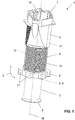
- the figures show a support device 1 for setting the height or position of a shower element and for supporting the shower element.
- the support device 1 is not only used to adjust the height or position but also to subsequently support the shower element.
- the support device 1 comprises a lower foot part 2 with a lower support surface 3, a middle foot part 4 with an actuating section 5 and an upper foot part 6 with an upper support surface 7.
- the lower support surface 3 is in contact with a building floor in the installed position.
- the shower element rests on the upper support surface 7.
- the storage can be indirect, for example via a profile or a frame or the like, or direct, with the shower element resting directly on the upper support surface 7 in the case of direct storage.
- An optional support element 38 which provides the lower support surface 3, is arranged here on the lower foot part 2.
- the support element 38 is preferably made of rubber or another material which has damping properties.
- a plumber can apply an adjustment movement E to the support device 1 via the actuation section 5, so that the distance between the two support surfaces 3, 7 can be adjusted.
- the central foot part 4 is pivoted about the central axis M.
- the distance between the two support surfaces 3, 7 defines the height of the support device 1.
- the lower foot part 2 has, opposite to the lower support surface 3, a lower threaded section 8, which engages with a first threaded section 9 of the central foot part 4.
- the lower threaded section 8 is designed as an external thread and the first threaded section 9 as an internal thread.
- the upper foot part 6 has, opposite to the upper support surface 7, an upper threaded section 10, which engages with a second threaded section 10 of the central foot part 4.
- the second threaded section 11 of the central foot part 4 is an external thread and the upper threaded section 10 is an internal thread.
- the central axis M extends centrally through the threaded sections 8, 9, 10, 11, which are each arranged concentrically to one another.
- the mentioned threaded sections 8, 9, 10, 11 each extend around a common central axis M.
- the central axis M is vertical in the installation position and the foot parts 2, 4, 6 move along the central axis M when the adjustment movement E is applied
- the lower foot part 2 and the upper foot part 6 move exclusively in the direction of the central axis M. That is, the lower foot part 2 and the upper foot part 6 move essentially in a straight line in the direction of the central axis M.
- the central foot part is pivoted about the central axis M. and also moves in the direction of the central axis M.
- the support device 1 also has an anti-rotation element 12.
- the anti-rotation element 12 is non-rotatably and longitudinally displaceable in contact with the lower foot part 2. Furthermore, the anti-rotation element 12 is also in contact with the upper foot part 6 in a rotationally fixed and longitudinally displaceable manner.
- the non-rotatable and longitudinally displaceable contact is such that the adjustment movement E on the middle foot part 4 via the mentioned thread engagements results in a longitudinal displacement along the central axis M between the lower foot part 2 and the upper foot part 6.
- the anti-rotation element 12 is mounted on the central foot part 5.
- the storage is designed in such a way that a rotation between the central base part 4 and the anti-rotation element 12 is possible and that a longitudinal displacement between the central base part 4 and the anti-rotation element 12 is made impossible.
- the anti-rotation element 12 has a latching tab 13 which is arranged at a distance from a stop section 31.
- a flange 32 of the central foot part 4 which extends circularly around the central axis M, protrudes into the space between the latching tab 13 and the stop section 31. During the adjustment movement E, the flange 32 slides through the space.
- the design of the threaded sections 8, 9, 10, 11 in the present case is such that the lower foot part 2 and the upper foot part 6 each move uniformly relative to the central foot part 4.
- the thread sections 8, 9, 10, 11 between the lower foot part 2 and the central foot part 4 and between the upper foot part 6 and the central foot part 4 have the same pitch.
- the threaded sections 8, 9 and the threaded sections 10, 11 are designed in opposite directions.
- the threaded sections 8, 9 are designed as right-hand threads and the threaded sections 10, 11 as left-hand threads.
- each of the foot parts 2, 4, 6 has a cavity 14, 15, 16 extending along the central axis M through the respective foot part 2, 4, 6.
- the anti-rotation element 12 extends from the cavity 14 of the lower foot part 2 through the cavity 15 of the middle foot part 4 and then protrudes into the cavity 16 of the upper foot part 6.
- Each of the cavities 14, 15, 16 is surrounded by an at least partially cylindrical side wall 33, 34, 35.
- the lower foot part 2 protrudes into the cavity 15 of the middle foot part 4 and the middle foot part 4 protrudes into the cavity 16 of the upper foot part 6.
- a kind of telescopic structure is created.
- the lower foot part 2 is displaceable relative to the cavity 15 of the central foot part 4.
- the middle foot part 4 is displaceable relative to the cavity 16 of the upper foot part 6.
- the lower threaded section 8 is arranged on the outside on the side wall 33 and the first thread section 9 cooperating with the lower threaded section 8 is arranged on the inside on the side wall 34.
- the upper threaded section 10 is arranged on the inside on the side wall 35 and the second thread section 11, which cooperates with the upper threaded section 10, is arranged on the outside of the side wall 34.
- the lower foot part 2 has at least one longitudinal guide 18.
- a guide comb 19 of the anti-rotation element 12 engages in this longitudinal guide 18.
- the engagement of the guide comb 19 in the longitudinal guide 18 is such that the non-rotatable and longitudinally displaceable contact can be provided between the lower foot part 2 and the anti-rotation element 12.
- the upper foot part 6 likewise has at least one longitudinal guide 20.
- a guide comb 39 of the anti-rotation element 12 also engages in this longitudinal guide in such a way that the non-rotatable and longitudinally displaceable contact can be provided between the upper foot part 6 and the anti-rotation element 12.
- the two longitudinal guides 18 and 20 are oriented in the same direction, namely in the direction of the central axis M.
- the longitudinal guides 18, 20 are arranged on a surface 29 of the side wall 33 or 34 facing the respective cavity 14, 16.
- a cylindrical section 28 extends from the stop section 31 of the anti-rotation element 12 away from the stop section 31.
- the longitudinal guide 20, in which the guide comb 19 engages, is arranged on the cylindrical section 28.
- the intermediate space 17 is designed to be ring-shaped when viewed in cross section, and the area of the lower foot part 2 which protrudes into the intermediate space 17 is likewise cylindrical when viewed in cross section.
- first threaded section 9 and the second threaded section 11 on the central foot part 4 extend essentially over the entire height of the central foot part 4.
- the lower threaded section 8 on the lower foot part 2 and the upper threaded section 10 on the upper foot part 6 only extend over a partial area of the entire height of the respective foot part.
- a haptic feedback structure 22 is present between the anti-rotation element 12 and the upper foot part 6.
- the haptic feedback structure 22 is a spring-mounted cam 36 which engages in corresponding recesses 37 when rotated. A relative movement between the cam 36 and the recesses 37 results in a Clicking noise that the plumber can hear.
- the actuating section On the outside, the actuating section has cams 21 protruding radially from the central foot part 4.
- the actuating section 5 of the central foot part 4 can be easily grasped via these cams 21.
- the stop element 23 strikes a stop surface 24 on the lower foot part 2 or the upper foot part 6 when the maximum extension movement is reached. This prevents the foot parts 2, 4, 6 from being rotated apart until they are separated from one another.
- the openings into which the haptic feedback structure 22 engages can also be seen.
- Adjustment movement 14th Lower foot part cavity M. Central axis 15th Cavity middle foot part 16 Cavity upper foot part 17th Space 18th Longitudinal guide 19th Guide comb 20th Longitudinal guide 21st cam 22nd haptic feedback structure 23 Stop element 24 Stop surface 26th Bearing profile
Landscapes
- Health & Medical Sciences (AREA)
- Public Health (AREA)
- Epidemiology (AREA)
- General Health & Medical Sciences (AREA)
- Life Sciences & Earth Sciences (AREA)
- Engineering & Computer Science (AREA)
- Hydrology & Water Resources (AREA)
- Water Supply & Treatment (AREA)
- Domestic Plumbing Installations (AREA)
- Massaging Devices (AREA)
Abstract
Description
- Die vorliegende Erfindung betrifft eine Stützvorrichtung zur Einstellung der Höhe eines Duschelementes, insbesondere einer Duschwanne oder einer Duschfläche, nach dem Oberbegriff von Anspruch 1.
- Aus der
EP 2 617 908 A1 ist eine Stützvorrichtung zur Einstellung der Höhe eines Duschelements bekannt geworden. Die Stützvorrichtung umfasst dabei in der Höhe einstellbare Fussteile, die jeweils zwei einstellbare Fussteile aufweisen. Die Höhe kann über die Drehung der Fussteile eingestellt werden. Nachteilig an der technischen Lehre derEP 2 617 908 A1 ist, dass es bei der Einstellung der Höhe aufgrund der Übertragung der Einstellbewegung auf andere Elemente zu einem unerwünschten Drehen von den Elementen kommt, welche für die Einstellbewegung nicht verdreht werden sollten. Das macht das Einstellen der Höhe für den Installateur mühsam. - Ausgehend von diesem Stand der Technik liegt der vorliegenden Erfindung eine Aufgabe zugrunde, eine Stützvorrichtung für die Einstellung der Höhe bzw. Lage eines Duschelementes, welche die Nachteile des Standes der Technik überwindet, anzugeben. Eine besonders bevorzugte Aufgabe ist es, eine Stützvorrichtung anzugeben, welche einfacher einstellbar ist.
- Diese Aufgabe löst der Gegenstand von Anspruch 1. Demgemäss umfasst eine Stützvorrichtung für die Einstellung der Höhe bzw. Lage eines Duschelementes ein unteres Fussteil mit einer unteren Stützfläche, ein mittleres Fussteil mit einem Betätigungsabschnitt und ein oberes Fussteil mit einer oberen Stützfläche. Das untere Fussteil weist gegenüberliegend zur unteren Stützfläche ein unterer Gewindeabschnitt auf, welcher mit einem ersten Gewindeabschnitt des mittleren Fussteils im Eingriff ist. Das obere Fussteil weist gegenüberliegend zur oberen Stützfläche ein oberer Gewindeabschnitt auf, welcher mit einem zweiten Gewindeabschnitt des mittleren Fussteils im Eingriff ist. Das mittlere Fussteil ist über den Betätigungsabschnitt um seine Mittelachse entlang einer Einstellbewegung drehbar. Die Stützvorrichtung weist weiterhin ein Verdrehsicherungselement auf, welches drehfest und längsverschieblich mit dem unteren Fussteil in Kontakt steht und welches drehfest und längsverschieblich mit dem oberen Fussteil in Kontakt steht, derart, dass bei einer auf das mittlere Fussteil wirkenden Einstellbewegung über die genannten Gewindeabschnitte eine Längsverschiebung zwischen dem unteren Fussteil und dem oberen Fussteil entlang der Mittelachse (M) resultiert.
- Durch die Anordnung des Verdrehsicherungselementes ergeht der Vorteil, dass bei einer Betätigung des mittleren Fussteils das obere und auch das untere Fussteil nicht verdreht werden. Hierdurch kann die Einstellung der Stützvorrichtung erleichtert werden.
- Unter der Ausdrucksweise "Duschelement" wird eine Duschwanne, eine Badewanne, eine Duschfläche, etc. verstanden.
- In Einbaulage gesehen steht die Stützvorrichtung mit der Stützfläche des unteren Fussteils auf dem Gebäudeboden auf und auf der Stützfläche des oberen Fussteils liegt das Duschelement oder ein Lagerprofil, auf welches das Duschelement zu liegen kommt. Eine umgekehrte Anordnung ist aber auch denkbar.
- Besonders vorteilhaft ist die Stützvorrichtung, wenn das obere Fussteil bereits in Verbindung mit dem Duschelement oder einem Lagerprofil, auf welches das Duschelement zu liegen kommt, ist. Typischerweise ist dann die Stützvorrichtung bereits vergleichsweise fest im Raum angeordnet und die Einstellbewegung kann mit einer Hand einhändig ausgeführt werden. Ein separates Halten der Stützvorrichtung mit einer zweiten Hand ist nicht nötig.
- Durch die Gewinde zwischen dem unteren Fussteil und dem mittleren Fussteil sowie zwischen dem oberen Fussteil und dem mittleren Fussteil resultiert bei Betätigung des mittleren Fussteils eine Relativbewegung des unteren Fussteils zum mittleren Fussteil und des oberen Fussteils zum mittleren Fussteil. Das heisst mit anderen Worten, dass das untere Fussteil und das obere Fussteil relativ zueinander verschoben, so dass die beiden zugeordneten Stützflächen sich ebenfalls relativ zueinander verschieben. Durch die relative Verschiebung der beiden Stützflächen zueinander kann die Höhe der Stützvorrichtung entsprechend angepasst werden.
- Das Verdrehsicherungselement ist bevorzugt derart angeordnet, dass bei einer Einstellbewegung des mittleren Fussteils, keine Drehbewegung auf das untere Fussteil bzw. das obere Fussteil resultiert.
- Vorzugsweise ist das Verdrehsicherungselement bezüglich einer Bewegung in Richtung der Mittelachse fest und bezüglich einer Bewegung um die Mittelachse bewegbar zum mittleren Fussteil befestigt, derart, dass sich das mittlere Fussteil um das feststehende Verdrehsicherungselement drehen kann.
- Vorzugsweise weist jedes der Fussteile einen sich entlang der Mittelachse durch das jeweilige Fussteil hindurch erstreckenden Hohlraum auf, wobei sich das Verdrehsicherungselement vom Hohlraum des unteren Fussteils durch den Hohlraum des mittleren Fussteils in den Hohlraum des oberen Fussteils erstreckt.
- Vorzugsweise ist jeder der Hohlräume durch eine mindestens teilweise zylindrisch ausgebildete Seitenwand umgeben, wobei die besagten Gewindeabschnitte an der Aussenseite bzw. an der dem Hohlraum zugewandten Innenseite der Seitenwand angeordnet sind.
- Vorzugsweise ragt das untere Fussteil in den Hohlraum des mittleren Fussteils ein und das mittlere Fussteil ragt in den Hohlraum des oberen Fussteils ein. Es resultiert demnach eine teleskopartige Struktur, wobei die Fussteile ineinander hinein drehbar sind. Hierdurch können vergleichsweise grosse Einstellbereiche abgedeckt werden.
- Vorzugsweise ist der Innendurchmesser des Hohlraums des oberen Fussteils grösser als der Aussendurchmesser des Hohlraums des mittleren Fussteils, so dass das mittlere Fussteil in den Hohlraum des oberen Fussteils bewegbar ist. Vorzugsweise ist der Innendurchmesser des Hohlraums des mittleren Fussteils grösser als der Aussendurchmesser des Hohlraums des unteren Fussteils, so dass das untere Fussteil in den Hohlraum des mittleren Fussteils bewegbar ist.
- Vorzugsweise ist zwischen dem mittleren Fussteil und dem oberen Fussteil ein Zwischenraum vorhanden, in welchen das untere Fussteil einragt.
- Vorzugsweise weist das untere Fussteil mindestens eine Längsführung auf, in welche ein Führungskamm des Verdrehsicherungselements derart eingreift, dass zwischen dem unteren Fussteil und dem Verdrehsicherungselement der drehfeste und längsverschiebliche Kontakt bereitstellbar ist.
- Vorzugsweise weist das obere Fussteil mindestens eine Längsführung auf, in welche ein Führungskamm des Verdrehsicherungselements derart eingreift, dass zwischen dem oberen Fussteil und dem Verdrehsicherungselements der drehfeste und längsverschiebliche Kontakt bereitstellbar ist.
- Vorzugsweise ist die mindestens eine Längsführung jeweils an bzw. in einer dem Hohlraum zugewandten Fläche der jeweiligen Fussteile angeordnet ist. Die Fläche ist dabei vorzugsweise Teil der oben genannten Seitenwand.
- Vorzugsweise ist der untere Gewindeabschnitt des unteren Fussteils und der erste Gewindeabschnitt des mittleren Fussteils als ein zum oberen Gewindeabschnitt des oberen Fussteils und dem zweiten Gewindeabschnitt des mittleren Fussteils gegen gängiges Gewinde ausgebildet ist. In einer ersten Variante ist der untere Gewindeabschnitt und der erste Gewindeabschnitt als rechtsgängiges Gewinde und der obere Gewindeabschnitt und der zweite Gewindeabschnitt als linksgängiges Gewinde ausgebildet. In einer zweiten Variante ist der untere Gewindeabschnitt und der erste Gewindeabschnitt als linksgängiges Gewinde und der obere Gewindeabschnitt und der zweite Gewindeabschnitt als rechtsgängiges Gewinde ausgebildet.
- Vorzugsweise erstrecken sich der erste Gewindeabschnitt und der zweite Gewindeabschnitt am mittleren Fussteil im Wesentlichen über die gesamte Höhe des mittleren Fussteils. Besonders bevorzugt sind der erste Gewindeabschnitt und der zweite Gewindeabschnitt im Wesentlichen gleich hoch. Die Summe der beiden Höhe ergibt der maximale Verstellbereich der Stützvorrichtung.
- Vorzugsweise erstrecken sich der untere Gewindeabschnitt am unteren Fussteil sowie der obere Gewindeabschnitt am oberen Fussteil nur über einen Teilbereich der gesamten Höhe des jeweiligen Fussteils.
- Vorzugsweise verfügt der Betätigungsabschnitt aussenseitig über radial zum mittleren Fussteil abstehende Nocken. Die Nocken sind vorzugsweise derart ausgebildet, dass diese eine Grösse aufweisen, welche von Hand gut ergriffen werden kann.
- Vorzugsweise ist zwischen dem Verdrehsicherungselement und dem unteren Fussteil und/oder zwischen dem Verdrehsicherungselement und dem oberen Fussteil eine haptische Rückmeldungsstruktur vorhanden, welche dem Benutzer bei der Einstellbewegung eine haptische Rückmeldung bereitstellt. Die haptische Rückmeldungsstruktur ist beispielsweise eine gefederte Nocke, die in passende Öffnungen einragt, wobei die Nocke relativ zur Öffnung bewegbar ist und wobei bei jedem Durchstreifen der Nocke durch die Öffnung ein Klackgeräusch abgebbar ist.
- Vorzugsweise weist das mittlere Fussteil ein Anschlagselement auf, welches in eine Anschlagsfläche am unteren Fussteil oder am oberen Fussteil anschlägt, wenn die maximale Ausfahrbewegung erreicht wird. Hierdurch kann sichergestellt werden, dass es bei der Einstellbewegung nicht zu einer Trennung des unteren bzw. oberen Fussteils vom mittleren Fussteil kommt.
- Vorzugsweise weist das obere Fussteil im Bereich seiner Stützfläche aussenseitig eine Raststruktur auf, mit welcher das obere Fussteil mit einem Lagerprofil für ein Duschelement oder mit einem Duschelement verrastbar ist.
- Weitere Ausführungsformen sind in den abhängigen Ansprüchen angegeben.
- Bevorzugte Ausführungsformen der Erfindung werden im Folgenden anhand der Zeichnungen beschrieben, die lediglich zur Erläuterung dienen und nicht einschränkend auszulegen sind. In den Zeichnungen zeigen:
- Fig. 1
- eine perspektivische Ansicht einer Stützvorrichtung für die Einstellung der Höhe eines Duschelementes nach einer Ausführungsform der vorliegenden Erfindung;
- Fig. 2
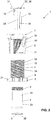
- eine Explosionsdarstellung der Stützvorrichtung nach
Figur 1 ; - Fig. 3
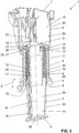
- eine geschnittene, perspektivische Ansicht der Stützvorrichtung nach
Figur 1 ; - Fig. 4
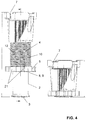
- zwei Ansicht der Stützvorrichtung nach
Figur 1 mit unterschiedlichen Höhen; - Fig. 5
- eine geschnittene, perspektivische Ansicht der Stützvorrichtung nach
Figur 1 ohne das Verdrehsicherungselement; und - Fig. 6
- eine perspektivische Ansicht einer Anordnung umfassend eine Stützvorrichtung nach den vorhergehenden Figuren und ein Lagerprofil für ein Duschelement.
- In den Figuren wird eine Stützvorrichtung 1 für die Einstellung der Höhe bzw. Lage eines Duschelementes und für die Abstützung des Duschelementes gezeigt. Die Stützvorrichtung 1 dient nicht nur der Einstellung der Höhe bzw. Lage sondern auch der anschliessenden Abstützung des Duschelementes.
- Die Stützvorrichtung 1 umfasst ein unteres Fussteil 2 mit einer unteren Stützfläche 3, ein mittleres Fussteil 4 mit einem Betätigungsabschnitt 5 und ein oberes Fussteil 6 mit einer oberen Stützfläche 7. Die untere Stützfläche 3 steht in der Einbaulage mit einem Gebäudeboden in Kontakt. Auf der oberen Stützfläche 7 lagert das Duschelement. Die Lagerung kann indirekt, beispielsweise über ein Profil oder ein Rahmen oder dergleichen, oder direkt sein, wobei bei der direkten Lagerung das Duschelement direkt auf der oberen Stützfläche 7 aufliegt. Typischerweise sind mehrere Stützvorrichtungen 1 für ein Duschelement anzuordnen. Am unteren Fussteil 2 ist hier ein optionales Auflageelement 38 angeordnet, welches die untere Stützfläche 3 bereitstellt. Das Auflageelement 38 ist vorzugsweise aus Gummi oder einem anderen Material, welches dämpfende Eigenschaften aufweist.
- Über den Betätigungsabschnitt 5 kann ein Sanitärinstallateur eine Einstellbewegung E auf die Stützvorrichtung 1 aufbringen, so dass der Abstand zwischen den beiden Stützflächen 3, 7 einstellbar wird. Bei der Einstellbewegung E wird das mittlere Fussteil 4 um die Mittelachse M verschwenkt. Der Abstand zwischen den beiden Stützflächen 3, 7, definiert die Höhe der Stützvorrichtung 1.
- Das untere Fussteil 2 weist gegenüberliegend zur unteren Stützfläche 3 einen unteren Gewindeabschnitt 8 auf, welcher mit einem ersten Gewindeabschnitt 9 des mittleren Fussteils 4 im Eingriff ist. Der untere Gewindeabschnitt 8 ist als Aussengewinde und der erste Gewindeabschnitt 9 als Innengewinde ausgebildet.
- Das obere Fussteil 6 weist gegenüberliegend zur oberen Stützfläche 7 einen oberen Gewindeabschnitt 10 auf, welcher mit einem zweiten Gewindeabschnitt 10 des mittleren Fussteils 4 im Eingriff ist. Der zweite Gewindeabschnitt 11 des mittleren Fussteils 4 ist ein Aussengewinde und der obere Gewindeabschnitt 10 ist ein Innengewinde.
- Die Mittelachse M erstreckt sich mittig durch die Gewindeabschnitte 8, 9, 10, 11, welche jeweils konzentrisch zueinander angeordnet sind.
- Der Eingriff der genannten Gewindeabschnitte 8, 9, 10, 11 wird in der
Figur 3 genauer gezeigt. Aufgrund des Gewindeeingriffes zwischen den Fussteilen 2, 4, 6 lässt sich durch die Einstellbewegung E die Distanz zwischen der unteren Stützfläche 3 und der oberen Stützfläche 7 einstellen. - Die erwähnten Gewindeabschnitte 8, 9, 10, 11 erstrecken sich jeweils um eine gemeinsame Mittelachse M. Die Mittelachse M steht in Einbaulage in der Vertikalen und die Fussteile 2, 4, 6 bewegen sich bei der Einwirkung der Einstellbewegung E entlang der Mittelachse M. Das untere Fussteil 2 und das obere Fussteil 6 bewegen sich dabei ausschliesslich in Richtung der Mittelachse M. Das heisst, das untere Fussteil 2 und das obere Fussteil 6 bewegen sich im Wesentlichen geradlinig in Richtung der Mittelachse M. Das mittlere Fussteil wird um die Mittelachse M verschwenkt und bewegt sich auch in Richtung der Mittelachse M.
- Weiter weist die Stützvorrichtung 1 ein Verdrehsicherungselement 12 auf. Das Verdrehsicherungselement 12 steht drehfest und längsverschieblich mit dem unteren Fussteil 2 in Kontakt. Weiter steht das Verdrehsicherungselement 12 ebenfalls drehfest und längsverschieblich mit dem oberen Fussteil 6 in Kontakt. Der drehfeste und längsverschiebliche Kontakt ist dabei derart, dass die Einstellbewegung E auf das mittlere Fussteil 4 über die genannten Gewindeeingriffe in einer Längsverschiebung entlang der Mittelachse M zwischen dem unteren Fussteil 2 und dem oberen Fussteil 6 resultiert. Bei einer Drehung auf das mittlere Fussteil 4 wird das untere Fussteil 2 und das obere Fussteil 6 durch das Verdrehsicherungselement 12 an einer Rotation verhindert und die Drehbewegung auf das mittlere Fussteil 4 resultiert aufgrund des Gewindeeingriffs und der beschriebenen Anordnung des Verdrehsicherungselementes 12 in eine Längsbewegung zwischen dem unteren Fussteil 2 und dem oberen Fussteil 6 entlang der Mittelachse M.
- Das Verdrehsicherungselement 12 ist am mittleren Fussteil 5 gelagert. Die Lagerung ist derart ausgebildet, dass eine Verdrehung zwischen dem mittleren Fussteil 4 und dem Verdrehsicherungselement 12 möglich ist und dass eine Längsverschiebung zwischen dem mittleren Fussteil 4 und dem Verdrehsicherungselement 12 verunmöglicht wird. In der gezeigten Ausführungsform weist das Verdrehsicherungselement 12 eine Rastlasche 13 auf, welche beabstandet zu einem Anschlagsabschnitt 31 angeordnet ist. In den Zwischenraum zwischen Rastlasche 13 und Anschlagsabschnitt 31 ragt ein zirkular um die Mittelachse M umlaufender Flansch 32 des mittleren Fussteils 4 ein. Bei der Einstellbewegung E gleitet der Flansch 32 durch den Zwischenraum.
- Die Ausbildung der Gewindeabschnitte 8, 9, 10, 11 ist im vorliegenden Fall derart, dass sich das untere Fussteil 2 und das obere Fussteil 6 jeweils gleichmässig relativ zum mittleren Fussteil 4 bewegen. Die Gewindeabschnitte 8, 9, 10, 11 zwischen dem unteren Fussteil 2 und dem mittleren Fussteil 4 und zwischen dem oberen Fussteil 6 und dem mittleren Fussteil 4 weisen die gleiche Steigung auf. Die Gewindeabschnitte 8, 9 und die Gewindeabschnitte 10, 11 sind aber gegengängig ausgebildet. Beispielsweise sind die Gewindeabschnitte 8, 9 als rechtsgängiges Gewinde und die Gewindeabschnitte 10, 11 als linksgängiges Gewinde ausgebildet.
- Von der
Figur 3 kann gut erkannt werden, dass jedes der Fussteile 2, 4, 6 einen entlang sich der Mittelachse M durch das jeweilige Fussteil 2, 4, 6 hindurch erstreckenden Hohlraum 14, 15, 16 aufweist. Das Verdrehsicherungselement 12 erstreckt sich vom Hohlraum 14 des unteren Fussteils 2 durch den Hohlraum 15 des mittleren Fussteils 4 und ragt dann in den Hohlraum 16 des oberen Fussteils 6 ein. Jeder der Hohlräume 14, 15, 16 wird jeweils durch eine mindestens teilweise zylindrisch ausgebildete Seitenwand 33, 34, 35 umgeben. In der gezeigten Ausführungsform ragt das untere Fussteil 2 in den Hohlraum 15 des mittleren Fussteils 4 ein und das mittlere Fussteil 4 ragt in den Hohlraum 16 des oberen Fussteils 6 ein. Es wird eine Art Teleskopstruktur geschaffen. Das untere Fussteil 2 ist relativ zum Hohlraum 15 des mittleren Fussteils 4 verschiebbar. Das mittlere Fussteil 4 ist relativ zum Hohlraum 16 des oberen Fussteils 6 verschiebbar. - Der untere Gewindeabschnitt 8 ist aussenseitig an der Seitenwand 33 angeordnet und der mit dem unteren Gewindeabschnitt 8 zusammenarbeitende erste Gewindeabschnitt 9 ist innenseitig an der Seitenwand 34 angeordnet. Der obere Gewindeabschnitt 10 ist innenseitig an der Seitenwand 35 angeordnet und der mit dem oberen Gewindeabschnitt 10 zusammenarbeitende zweite Gewindeabschnitt 11 ist aussenseitig an der Seitenwand 34 angeordnet.
- In der gezeigten Ausführungsform weist das untere Fussteil 2 mindestens eine Längsführung 18 auf. In dieser Längsführung 18 greift ein Führungskamm 19 des Verdrehsicherungselementes 12 ein. Der Eingriff des Führungskammes 19 in die Längsführung 18 ist dabei derart, dass zwischen dem unteren Fussteil 2 und dem Verdrehsicherungselement 12 der drehfeste und längsverschiebliche Kontakt bereitstellbar ist. Gleichermassen weist das obere Fussteil 6 mindestens eine Längsführung 20 auf. Auch in diese Längsführung greift ein Führungskamm 39 des Verdrehsicherungselementes 12 derart ein, dass zwischen dem oberen Fussteil 6 und dem Verdrehsicherungselement 12 der drehfeste und längsverschiebliche Kontakt bereitstellbar ist. Die beiden Längsführungen 18 und 20 sind in die gleiche Richtung, nämlich in Richtung der Mittelachse M orientiert.
- Die Längsführungen 18, 20 sind an eine dem jeweiligen Hohlraum 14, 16 zugewandten Fläche 29 der Seitenwand 33 bzw. 34 angeordnet.
- In der gezeigten Ausführungsform erstreckt sich vom Anschlagsabschnitt 31 des Verdrehsicherungselementes 12 ein zylindrischer Abschnitt 28 vom Anschlagsabschnitt 31 weg. Am zylindrischen Abschnitt 28 ist die Längsführung 20 angeordnet, in welche der Führungskamm 19 eingreift. Zwischen dem ersten Gewindeabschnitt 9 und dem zylindrischen Abschnitt 28 ist ein Zwischenraum 17 vorhanden, in welche sich das untere Fussteil 2 hineinerstrecken kann. Der Zwischenraum 17 ist im Querschnitt gesehen ringförmig ausgebildet und der Bereich des unteren Fussteils 2, der in den Zwischenraum 17 einragt ist im Querschnitt gesehen ebenfalls zylindrisch ausgebildet.
- Von der
Figur 3 kann weiter erkannt werden, dass sich der erste Gewindeabschnitt 9 und der zweite Gewindeabschnitt 11 am mittleren Fussteil 4 im Wesentlichen über die gesamte Höhe des mittleren Fussteils 4 erstrecken. Der untere Gewindeabschnitt 8 am unteren Fussteil 2 und der obere Gewindeabschnitt 10 am oberen Fussteil 6 erstreckt sich nur über einen Teilbereich der gesamten Höhe des jeweiligen Fussteils. - Weiter ist, wie in der
Figur 3 gezeigt, zwischen den Verdrehsicherungselement 12 und dem oberen Fussteil 6 eine haptische Rückmeldungsstruktur 22 vorhanden. In der gezeigten Ausführungsform ist die haptische Rückmeldungsstruktur 22 eine gefedert gelagerte Nocke 36, welche bei einer Verdrehung in entsprechende Ausnehmungen 37 eingreift. Bei einer Relativbewegung zwischen Nocke 36 und den Ausnehmungen 37 resultiert ein Klackgeräusch, welches der Sanitärinstallateur wahrnehmen kann. - In der
Figur 4 wird die Stützvorrichtung 1 einmal im vollständig ausgefahrenen Zustand (Darstellung links) und im vollständig eingefahrenen Zustand (Darstellung rechts) gezeigt. - Der Betätigungsabschnitt weist aussenseitig radial zum mittleren Fussteil 4 abstehende Nocken 21 auf. Über diese Nocken 21 kann der Betätigungsabschnitt 5 des mittleren Fussteils 4 einfach ergriffen werden.
- Weiter weist das mittlere Fussteil 4, wie in der
Figur 5 gezeigt, ein Anschlagselement 23 auf. Das Anschlagselement 23 schlägt an einer Anschlagsfläche 24 am unteren Fussteil 2 oder am oberen Fussteil 6 an, wenn die maximale Ausfahrbewegung erreicht wird. Hierdurch wird verhindert, dass die Fussteile 2, 4, 6 soweit auseinandergedreht werden, bis diese voneinander getrennt werden. Von derFigur 5 sind im Weiteren die Öffnungen erkennbar, in welche die haptische Rückmeldungsstruktur 22 eingreift. - Die
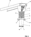
Figur 6 zeigt sodann eine Anordnung, welche eine Stützvorrichtung 1 gemäss obiger Beschreibung umfasst und welche weiterhin ein Lagerprofil 26 zur Lagerung eines nicht gezeigten Duschelementes aufweist. Das Lagerprofil 26 weist einen Aufnahmeraum 30 auf, in welche das obere Fussteil 6 eingerastet werden kann, sodass die obere Stützfläche 7 mit der Handfläche des Aufnahmeraums 30 in Kontakt bringbar ist.BEZUGSZEICHENLISTE 1 Stützvorrichtung 28 zylindrischer Abschnitt 2 unteres Fussteil 29 Fläche 3 untere Stützfläche 30 Aufnahmeraum 4 mittleres Fussteil 31 Anschlagsabschnitt 5 Betätigungsabschnitt 32 Flansch 6 oberes Fussteil 33 Seitenwand 7 obere Stützfläche 34 Seitenwand 8 unterer Gewindeabschnitt 35 Seitenwand 9 erster Gewindeabschnitt 36 gefederte Nocke 10 oberer Gewindeabschnitt 37 Ausnehmungen 11 zweiter Gewindeabschnitt 38 Auflageelement 12 Verdrehsicherungselement 39 Führungskamm 13 Rastlasche E Einstellbewegung 14 Hohlraum unteres Fussteil M Mittelachse 15 Hohlraum mittleres Fussteil 16 Hohlraum oberes Fussteil 17 Zwischenraum 18 Längsführung 19 Führungskamm 20 Längsführung 21 Nocken 22 haptische Rückmeldungsstruktur 23 Anschlagselement 24 Anschlagsfläche 26 Lagerprofil
Claims (15)
- Stützvorrichtung (1) für die Einstellung der Höhe eines Duschelementes und die Abstützung des Duschelementes umfassend,
ein unteres Fussteil (2) mit einer unteren Stützfläche (3),
ein mittleres Fussteil (4) mit einem Betätigungsabschnitt (5) und
ein oberes Fussteil (6) mit einer oberen Stützfläche (7),
wobei das untere Fussteil (2) gegenüberliegend zur unteren Stützfläche (3) ein unterer Gewindeabschnitt (8) aufweist, welcher mit einem ersten Gewindeabschnitt (9) des mittleren Fussteils (4) im Eingriff ist,
wobei das obere Fussteil (6) gegenüberliegend zur oberen Stützfläche (7) ein oberer Gewindeabschnitt (10) aufweist, welcher mit einem zweiten Gewindeabschnitt (11) des mittleren Fussteils (4) im Eingriff ist,
wobei das mittlere Fussteil (4) über den Betätigungsabschnitt (5) um seine Mittelachse (M) entlang einer Einstellbewegung (E) drehbar ist, und
wobei die Stützvorrichtung (1) weiterhin ein Verdrehsicherungselement (12) aufweist, welches drehfest und längsverschieblich mit dem unteren Fussteil (2) in Kontakt steht und welches drehfest und längsverschieblich mit dem oberen Fussteil (6) in Kontakt steht, derart, dass bei einer auf das mittlere Fussteil (4) wirkenden Einstellbewegung (E) über die genannten Gewindeabschnitte (8, 9, 10, 11) eine Längsverschiebung zwischen dem unteren Fussteil (2) und dem oberen Fussteil (6) entlang der Mittelachse (M) resultiert. - Stützvorrichtung (1) nach Anspruch 1, dadurch gekennzeichnet, dass das Verdrehsicherungselement (12) derart angeordnet ist, dass bei einer Einstellbewegung (E) des mittleren Fussteils (4), keine Drehbewegung auf das untere Fussteil (2) bzw. das obere Fussteil (6) resultiert.
- Stützvorrichtung (1) nach Anspruch 1 oder 2, dadurch gekennzeichnet, dass das Verdrehsicherungselement (12) bezüglich einer Bewegung in Richtung der Mittelachse (M) fest und bezüglich einer Bewegung um die Mittelachse (M) bewegbar zum mittleren Fussteil (4) befestigt ist.
- Stützvorrichtung (1) nach einem der vorhergehenden Ansprüche, dadurch gekennzeichnet, dass jedes der Fussteile (2, 4, 6) einen sich entlang der Mittelachse (M) durch das jeweilige Fussteil (2, 4, 6) hindurch erstreckenden Hohlraum (14, 15, 16) aufweist, wobei sich das Verdrehsicherungselement (12) vom Hohlraum (14) des unteren Fussteils (2) durch den Hohlraum (15) des mittleren Fussteils (15) in den Hohlraum (16) des oberen Fussteils (6) erstreckt.
- Stützvorrichtung nach Anspruch 4, dadurch gekennzeichnet, dass jeder der Hohlräume (14, 15, 16) durch eine mindestens teilweise zylindrisch ausgebildete Seitenwand (33, 34, 35) umgeben ist, wobei die besagten Gewindeabschnitte (8, 9, 10, 11) an der Aussenseite bzw. an der dem Hohlraum (14, 15, 16) zugewandten Innenseite der Seitenwand (33, 34, 35) angeordnet sind.
- Stützvorrichtung (1) nach Anspruch 4 oder 5, dadurch gekennzeichnet, dass das untere Fussteil (2) in den Hohlraum (15) des mittleren Fussteils (4) einragt und dass das mittlere Fussteil (4) in den Hohlraum (16) des oberen Fussteils (6) einragt und/oder dass zwischen dem mittleren Fussteil (4) und dem oberen Fussteil (6) ein Zwischenraum (17) vorhanden ist, in welchen das untere Fussteil (2) einragt.
- Stützvorrichtung (1) nach einem der vorhergehenden Ansprüche, dadurch gekennzeichnet,
dass das untere Fussteil (2) mindestens eine Längsführung (18) aufweist, in welche ein Führungskamm (19) des Verdrehsicherungselements (12) derart eingreift, dass zwischen dem unteren Fussteil (2) und dem Verdrehsicherungselements (12) der drehfeste und längsverschiebliche Kontakt bereitstellbar ist und/oder
dass das obere Fussteil (6) mindestens eine Längsführung (20) aufweist, in welche ein Führungskamm (39) des Verdrehsicherungselements (12) derart eingreift, dass zwischen dem oberen Fussteil (6) und dem Verdrehsicherungselements (12) der drehfeste und längsverschiebliche Kontakt bereitstellbar ist. - Stützvorrichtung (1) nach Anspruch 7, dadurch gekennzeichnet, dass die mindestens eine Längsführung (18, 20) jeweils an bzw. in einer dem Hohlraum (14, 16) zugewandten Fläche (29) angeordnet ist.
- Stützvorrichtung (1) nach einem der vorhergehenden Ansprüche, dadurch gekennzeichnet, dass der untere Gewindeabschnitt (8) des unteren Fussteils (2) und der erste Gewindeabschnitt (9) des mittleren Fussteils (4) als ein zum oberen Gewindeabschnitt (10) des oberen Fussteils (6) und dem zweiten Gewindeabschnitt (11) des mittleren Fussteils (4) gegen gängiges Gewinde ausgebildet ist.
- Stützvorrichtung (1) nach einem der vorhergehenden Ansprüche, dadurch gekennzeichnet, dass sich der erste Gewindeabschnitt (9) und der zweite Gewindeabschnitt (11) am mittleren Fussteil (4) im Wesentlichen über die gesamte Höhe des mittleren Fussteils (4) erstrecken und/oder dass sich der untere Gewindeabschnitt (8) am unteren Fussteil (2) sowie der obere Gewindeabschnitt (10) am oberen Fussteil (6) nur über einen Teilbereich der gesamten Höhe des jeweiligen Fussteils (2, 6) erstrecken.
- Stützvorrichtung (1) nach einem der vorhergehenden Ansprüche, dadurch gekennzeichnet, dass der Betätigungsabschnitt (5) aussenseitig über radial zum mittleren Fussteil (4) abstehende Nocken (21) verfügt.
- Stützvorrichtung (1) nach einem der vorhergehenden Ansprüche, dadurch gekennzeichnet, dass zwischen dem Verdrehsicherungselement (12) und dem unteren Fussteil (2) und/oder zwischen dem Verdrehsicherungselement (12) und dem oberen Fussteil (6) eine haptische Rückmeldungsstruktur (22) vorhanden ist, welche dem Benutzer bei der Einstellbewegung (E) eine haptische Rückmeldung bereitstellt.
- Stützvorrichtung (1) nach einem der vorhergehenden Ansprüche, dadurch gekennzeichnet, dass das mittlere Fussteil (4) ein Anschlagselement (23) aufweist, welches an einer Anschlagsfläche (24) am unteren Fussteil (2) oder am oberen Fussteil (6) anschlägt, wenn die maximale Ausfahrbewegung erreicht wird.
- Stützvorrichtung (1) nach einem der vorhergehenden Ansprüche, dadurch gekennzeichnet, dass das obere Fussteil (6) im Bereich seiner Stützfläche (3) aussenseitig eine Raststruktur (25) aufweist, mit welcher das obere Fussteil (6) mit einem Lagerprofil (26) für ein Duschelement verrastbar ist.
- Anordnung umfassend- mindestens eine Stützvorrichtung (1) nach einem der vorhergehenden Ansprüche und ein Lagerprofil sowie ein auf dem Lagerprofil aufliegendes Duschelement, wobei die Stützvorrichtung mit dem oberen Fussteil am Lagerprofil befestigbar ist; oder- mindestens eine Stützvorrichtung (1) nach einem der vorhergehenden Ansprüche und ein Duschelement, wobei die Stützvorrichtung mit dem oberen Fussteil am Duschelement befestigbar ist.
Priority Applications (3)
| Application Number | Priority Date | Filing Date | Title |
|---|---|---|---|
| EP19187020.3A EP3766396B1 (de) | 2019-07-18 | 2019-07-18 | Stützvorrichtung |
| ES19187020T ES2910299T3 (es) | 2019-07-18 | 2019-07-18 | Dispositivo de soporte |
| CH01645/19A CH715799B1 (de) | 2019-07-18 | 2019-12-18 | Stützvorrichtung. |
Applications Claiming Priority (1)
| Application Number | Priority Date | Filing Date | Title |
|---|---|---|---|
| EP19187020.3A EP3766396B1 (de) | 2019-07-18 | 2019-07-18 | Stützvorrichtung |
Publications (2)
| Publication Number | Publication Date |
|---|---|
| EP3766396A1 true EP3766396A1 (de) | 2021-01-20 |
| EP3766396B1 EP3766396B1 (de) | 2022-02-23 |
Family
ID=67438001
Family Applications (1)
| Application Number | Title | Priority Date | Filing Date |
|---|---|---|---|
| EP19187020.3A Active EP3766396B1 (de) | 2019-07-18 | 2019-07-18 | Stützvorrichtung |
Country Status (3)
| Country | Link |
|---|---|
| EP (1) | EP3766396B1 (de) |
| CH (1) | CH715799B1 (de) |
| ES (1) | ES2910299T3 (de) |
Cited By (1)
| Publication number | Priority date | Publication date | Assignee | Title |
|---|---|---|---|---|
| DE102024205014B4 (de) * | 2023-06-16 | 2026-05-13 | Witte Automotive Gmbh | Vorrichtung zum Ausgleichen von Toleranzen |
Citations (2)
| Publication number | Priority date | Publication date | Assignee | Title |
|---|---|---|---|---|
| DE10064881A1 (de) * | 2000-12-27 | 2002-07-11 | Mepa Pauli Und Menden Gmbh | Fusslager für höhenverstellbare Füsse eines Traggestells für Bade- und Brausewannen |
| EP2617908A1 (de) | 2012-01-20 | 2013-07-24 | Easy Sanitairy Solutions B.V. | Vorrichtung zur Höhenverstellung eines Dusch- oder Rinnenablaufs |
-
2019
- 2019-07-18 EP EP19187020.3A patent/EP3766396B1/de active Active
- 2019-07-18 ES ES19187020T patent/ES2910299T3/es active Active
- 2019-12-18 CH CH01645/19A patent/CH715799B1/de not_active IP Right Cessation
Patent Citations (2)
| Publication number | Priority date | Publication date | Assignee | Title |
|---|---|---|---|---|
| DE10064881A1 (de) * | 2000-12-27 | 2002-07-11 | Mepa Pauli Und Menden Gmbh | Fusslager für höhenverstellbare Füsse eines Traggestells für Bade- und Brausewannen |
| EP2617908A1 (de) | 2012-01-20 | 2013-07-24 | Easy Sanitairy Solutions B.V. | Vorrichtung zur Höhenverstellung eines Dusch- oder Rinnenablaufs |
Cited By (1)
| Publication number | Priority date | Publication date | Assignee | Title |
|---|---|---|---|---|
| DE102024205014B4 (de) * | 2023-06-16 | 2026-05-13 | Witte Automotive Gmbh | Vorrichtung zum Ausgleichen von Toleranzen |
Also Published As
| Publication number | Publication date |
|---|---|
| CH715799B1 (de) | 2020-07-31 |
| EP3766396B1 (de) | 2022-02-23 |
| ES2910299T3 (es) | 2022-05-12 |
Similar Documents
| Publication | Publication Date | Title |
|---|---|---|
| EP1868466B1 (de) | Armlehne, insbesondere für einen bürostuhl | |
| DE3429424C2 (de) | ||
| DE102010000970C5 (de) | Höhenverstellbare Betätigungs-Einrichtung | |
| EP3068963B1 (de) | Scharnier, insbesondere für ein möbelstück | |
| DE69310834T2 (de) | Vorrichtung für die Neigungsverstellung von Bett- oder Sofateilen | |
| EP1694257A2 (de) | Längenverstellbares wirbelsäulen-implantat | |
| DE1778196C3 (de) | Hubvorrichtung für ein Sitzmöbel | |
| EP0641532A1 (de) | Längenverstellbare Säule für Stühle, Tische o.dgl. | |
| EP0982018B1 (de) | Hubvorrichtung vorzugsweise für die Höhenverstellung eines Kranken- oder Pflegebetts | |
| EP3428353A1 (de) | Wandhalterung für einen sanitärartikel | |
| EP3889485A2 (de) | Abwassertankanordnung für ein flugzeug | |
| EP3708726B1 (de) | Sanitärartikelanordnung mit höhenverstellung | |
| EP3766396B1 (de) | Stützvorrichtung | |
| WO2016001371A1 (de) | Montagevorrichtung | |
| DE102017127700A1 (de) | Hubaggregat | |
| DE102022116843B4 (de) | Verbindungsanordnung, Säule, Möbelstück und Verfahren zum Herstellen einer Säule | |
| DE10340725B4 (de) | Hubaggregat für Tische oder dergleichen | |
| DE29800015U1 (de) | Teleskopsäule | |
| EP2941148B1 (de) | Korpuspositionierung bei einem möbelmodul | |
| DE3901322A1 (de) | Brausekopf mit einer verstelleinrichtung | |
| CH707352B1 (de) | Teleskopierbarer Spindelantrieb und ein Tischmöbel mit einem teleskopierbaren Spindelantrieb. | |
| DE19529255C2 (de) | Arretier- und Verstelleinrichtung | |
| EP3321435A1 (de) | Ablaufgarnituranordnung | |
| CH720298A2 (de) | Betätigungsmechanismus, Möbelarretieranordnung, Möbel und Verfahren zum selektiven Hemmen einer Bewegung eines Möbels. | |
| DE102004034624B3 (de) | Vorrichtung zum Verstellen einer Sitzposition |
Legal Events
| Date | Code | Title | Description |
|---|---|---|---|
| PUAI | Public reference made under article 153(3) epc to a published international application that has entered the european phase |
Free format text: ORIGINAL CODE: 0009012 |
|
| STAA | Information on the status of an ep patent application or granted ep patent |
Free format text: STATUS: THE APPLICATION HAS BEEN PUBLISHED |
|
| AK | Designated contracting states |
Kind code of ref document: A1 Designated state(s): AL AT BE BG CH CY CZ DE DK EE ES FI FR GB GR HR HU IE IS IT LI LT LU LV MC MK MT NL NO PL PT RO RS SE SI SK SM TR |
|
| AX | Request for extension of the european patent |
Extension state: BA ME |
|
| STAA | Information on the status of an ep patent application or granted ep patent |
Free format text: STATUS: REQUEST FOR EXAMINATION WAS MADE |
|
| 17P | Request for examination filed |
Effective date: 20210601 |
|
| RBV | Designated contracting states (corrected) |
Designated state(s): AL AT BE BG CH CY CZ DE DK EE ES FI FR GB GR HR HU IE IS IT LI LT LU LV MC MK MT NL NO PL PT RO RS SE SI SK SM TR |
|
| GRAP | Despatch of communication of intention to grant a patent |
Free format text: ORIGINAL CODE: EPIDOSNIGR1 |
|
| STAA | Information on the status of an ep patent application or granted ep patent |
Free format text: STATUS: GRANT OF PATENT IS INTENDED |
|
| INTG | Intention to grant announced |
Effective date: 20211001 |
|
| RIC1 | Information provided on ipc code assigned before grant |
Ipc: E03F 5/04 20060101ALN20210920BHEP Ipc: F16B 5/02 20060101ALI20210920BHEP Ipc: A47K 3/17 20060101AFI20210920BHEP |
|
| GRAS | Grant fee paid |
Free format text: ORIGINAL CODE: EPIDOSNIGR3 |
|
| GRAA | (expected) grant |
Free format text: ORIGINAL CODE: 0009210 |
|
| STAA | Information on the status of an ep patent application or granted ep patent |
Free format text: STATUS: THE PATENT HAS BEEN GRANTED |
|
| AK | Designated contracting states |
Kind code of ref document: B1 Designated state(s): AL AT BE BG CH CY CZ DE DK EE ES FI FR GB GR HR HU IE IS IT LI LT LU LV MC MK MT NL NO PL PT RO RS SE SI SK SM TR |
|
| REG | Reference to a national code |
Ref country code: GB Ref legal event code: FG4D Free format text: NOT ENGLISH |
|
| REG | Reference to a national code |
Ref country code: CH Ref legal event code: EP |
|
| REG | Reference to a national code |
Ref country code: AT Ref legal event code: REF Ref document number: 1469796 Country of ref document: AT Kind code of ref document: T Effective date: 20220315 |
|
| REG | Reference to a national code |
Ref country code: IE Ref legal event code: FG4D Free format text: LANGUAGE OF EP DOCUMENT: GERMAN |
|
| REG | Reference to a national code |
Ref country code: DE Ref legal event code: R096 Ref document number: 502019003468 Country of ref document: DE |
|
| REG | Reference to a national code |
Ref country code: ES Ref legal event code: FG2A Ref document number: 2910299 Country of ref document: ES Kind code of ref document: T3 Effective date: 20220512 |
|
| REG | Reference to a national code |
Ref country code: LT Ref legal event code: MG9D |
|
| REG | Reference to a national code |
Ref country code: NL Ref legal event code: MP Effective date: 20220223 |
|
| PG25 | Lapsed in a contracting state [announced via postgrant information from national office to epo] |
Ref country code: SE Free format text: LAPSE BECAUSE OF FAILURE TO SUBMIT A TRANSLATION OF THE DESCRIPTION OR TO PAY THE FEE WITHIN THE PRESCRIBED TIME-LIMIT Effective date: 20220223 Ref country code: RS Free format text: LAPSE BECAUSE OF FAILURE TO SUBMIT A TRANSLATION OF THE DESCRIPTION OR TO PAY THE FEE WITHIN THE PRESCRIBED TIME-LIMIT Effective date: 20220223 Ref country code: PT Free format text: LAPSE BECAUSE OF FAILURE TO SUBMIT A TRANSLATION OF THE DESCRIPTION OR TO PAY THE FEE WITHIN THE PRESCRIBED TIME-LIMIT Effective date: 20220623 Ref country code: NO Free format text: LAPSE BECAUSE OF FAILURE TO SUBMIT A TRANSLATION OF THE DESCRIPTION OR TO PAY THE FEE WITHIN THE PRESCRIBED TIME-LIMIT Effective date: 20220523 Ref country code: NL Free format text: LAPSE BECAUSE OF FAILURE TO SUBMIT A TRANSLATION OF THE DESCRIPTION OR TO PAY THE FEE WITHIN THE PRESCRIBED TIME-LIMIT Effective date: 20220223 Ref country code: LT Free format text: LAPSE BECAUSE OF FAILURE TO SUBMIT A TRANSLATION OF THE DESCRIPTION OR TO PAY THE FEE WITHIN THE PRESCRIBED TIME-LIMIT Effective date: 20220223 Ref country code: HR Free format text: LAPSE BECAUSE OF FAILURE TO SUBMIT A TRANSLATION OF THE DESCRIPTION OR TO PAY THE FEE WITHIN THE PRESCRIBED TIME-LIMIT Effective date: 20220223 Ref country code: BG Free format text: LAPSE BECAUSE OF FAILURE TO SUBMIT A TRANSLATION OF THE DESCRIPTION OR TO PAY THE FEE WITHIN THE PRESCRIBED TIME-LIMIT Effective date: 20220523 |
|
| PG25 | Lapsed in a contracting state [announced via postgrant information from national office to epo] |
Ref country code: PL Free format text: LAPSE BECAUSE OF FAILURE TO SUBMIT A TRANSLATION OF THE DESCRIPTION OR TO PAY THE FEE WITHIN THE PRESCRIBED TIME-LIMIT Effective date: 20220223 Ref country code: LV Free format text: LAPSE BECAUSE OF FAILURE TO SUBMIT A TRANSLATION OF THE DESCRIPTION OR TO PAY THE FEE WITHIN THE PRESCRIBED TIME-LIMIT Effective date: 20220223 Ref country code: GR Free format text: LAPSE BECAUSE OF FAILURE TO SUBMIT A TRANSLATION OF THE DESCRIPTION OR TO PAY THE FEE WITHIN THE PRESCRIBED TIME-LIMIT Effective date: 20220524 Ref country code: FI Free format text: LAPSE BECAUSE OF FAILURE TO SUBMIT A TRANSLATION OF THE DESCRIPTION OR TO PAY THE FEE WITHIN THE PRESCRIBED TIME-LIMIT Effective date: 20220223 |
|
| PG25 | Lapsed in a contracting state [announced via postgrant information from national office to epo] |
Ref country code: IS Free format text: LAPSE BECAUSE OF FAILURE TO SUBMIT A TRANSLATION OF THE DESCRIPTION OR TO PAY THE FEE WITHIN THE PRESCRIBED TIME-LIMIT Effective date: 20220623 |
|
| PG25 | Lapsed in a contracting state [announced via postgrant information from national office to epo] |
Ref country code: SM Free format text: LAPSE BECAUSE OF FAILURE TO SUBMIT A TRANSLATION OF THE DESCRIPTION OR TO PAY THE FEE WITHIN THE PRESCRIBED TIME-LIMIT Effective date: 20220223 Ref country code: SK Free format text: LAPSE BECAUSE OF FAILURE TO SUBMIT A TRANSLATION OF THE DESCRIPTION OR TO PAY THE FEE WITHIN THE PRESCRIBED TIME-LIMIT Effective date: 20220223 Ref country code: RO Free format text: LAPSE BECAUSE OF FAILURE TO SUBMIT A TRANSLATION OF THE DESCRIPTION OR TO PAY THE FEE WITHIN THE PRESCRIBED TIME-LIMIT Effective date: 20220223 Ref country code: EE Free format text: LAPSE BECAUSE OF FAILURE TO SUBMIT A TRANSLATION OF THE DESCRIPTION OR TO PAY THE FEE WITHIN THE PRESCRIBED TIME-LIMIT Effective date: 20220223 Ref country code: DK Free format text: LAPSE BECAUSE OF FAILURE TO SUBMIT A TRANSLATION OF THE DESCRIPTION OR TO PAY THE FEE WITHIN THE PRESCRIBED TIME-LIMIT Effective date: 20220223 Ref country code: CZ Free format text: LAPSE BECAUSE OF FAILURE TO SUBMIT A TRANSLATION OF THE DESCRIPTION OR TO PAY THE FEE WITHIN THE PRESCRIBED TIME-LIMIT Effective date: 20220223 |
|
| REG | Reference to a national code |
Ref country code: DE Ref legal event code: R097 Ref document number: 502019003468 Country of ref document: DE |
|
| PG25 | Lapsed in a contracting state [announced via postgrant information from national office to epo] |
Ref country code: AL Free format text: LAPSE BECAUSE OF FAILURE TO SUBMIT A TRANSLATION OF THE DESCRIPTION OR TO PAY THE FEE WITHIN THE PRESCRIBED TIME-LIMIT Effective date: 20220223 |
|
| PLBE | No opposition filed within time limit |
Free format text: ORIGINAL CODE: 0009261 |
|
| STAA | Information on the status of an ep patent application or granted ep patent |
Free format text: STATUS: NO OPPOSITION FILED WITHIN TIME LIMIT |
|
| 26N | No opposition filed |
Effective date: 20221124 |
|
| PG25 | Lapsed in a contracting state [announced via postgrant information from national office to epo] |
Ref country code: SI Free format text: LAPSE BECAUSE OF FAILURE TO SUBMIT A TRANSLATION OF THE DESCRIPTION OR TO PAY THE FEE WITHIN THE PRESCRIBED TIME-LIMIT Effective date: 20220223 Ref country code: MC Free format text: LAPSE BECAUSE OF FAILURE TO SUBMIT A TRANSLATION OF THE DESCRIPTION OR TO PAY THE FEE WITHIN THE PRESCRIBED TIME-LIMIT Effective date: 20220223 |
|
| PG25 | Lapsed in a contracting state [announced via postgrant information from national office to epo] |
Ref country code: LU Free format text: LAPSE BECAUSE OF NON-PAYMENT OF DUE FEES Effective date: 20220718 |
|
| P01 | Opt-out of the competence of the unified patent court (upc) registered |
Effective date: 20230516 |
|
| PG25 | Lapsed in a contracting state [announced via postgrant information from national office to epo] |
Ref country code: IE Free format text: LAPSE BECAUSE OF NON-PAYMENT OF DUE FEES Effective date: 20220718 |
|
| GBPC | Gb: european patent ceased through non-payment of renewal fee |
Effective date: 20230718 |
|
| PG25 | Lapsed in a contracting state [announced via postgrant information from national office to epo] |
Ref country code: MK Free format text: LAPSE BECAUSE OF FAILURE TO SUBMIT A TRANSLATION OF THE DESCRIPTION OR TO PAY THE FEE WITHIN THE PRESCRIBED TIME-LIMIT Effective date: 20220223 Ref country code: CY Free format text: LAPSE BECAUSE OF FAILURE TO SUBMIT A TRANSLATION OF THE DESCRIPTION OR TO PAY THE FEE WITHIN THE PRESCRIBED TIME-LIMIT Effective date: 20220223 Ref country code: GB Free format text: LAPSE BECAUSE OF NON-PAYMENT OF DUE FEES Effective date: 20230718 |
|
| PG25 | Lapsed in a contracting state [announced via postgrant information from national office to epo] |
Ref country code: HU Free format text: LAPSE BECAUSE OF FAILURE TO SUBMIT A TRANSLATION OF THE DESCRIPTION OR TO PAY THE FEE WITHIN THE PRESCRIBED TIME-LIMIT; INVALID AB INITIO Effective date: 20190718 |
|
| PG25 | Lapsed in a contracting state [announced via postgrant information from national office to epo] |
Ref country code: TR Free format text: LAPSE BECAUSE OF FAILURE TO SUBMIT A TRANSLATION OF THE DESCRIPTION OR TO PAY THE FEE WITHIN THE PRESCRIBED TIME-LIMIT Effective date: 20220223 |
|
| REG | Reference to a national code |
Ref country code: BE Ref legal event code: PD Owner name: GEBERIT HOLDING AG; CH Free format text: DETAILS ASSIGNMENT: CHANGE OF OWNER(S), MERGE; FORMER OWNER NAME: GEBERIT INTERNATIONAL AG Effective date: 20240528 Ref country code: BE Ref legal event code: HC Owner name: GEBERIT INTERNATIONAL AG; CH Free format text: DETAILS ASSIGNMENT: CHANGE OF OWNER(S), CHANGE OF OWNER(S) NAME; FORMER OWNER NAME: GEBERIT HOLDING AG Effective date: 20240528 |
|
| PG25 | Lapsed in a contracting state [announced via postgrant information from national office to epo] |
Ref country code: MT Free format text: LAPSE BECAUSE OF FAILURE TO SUBMIT A TRANSLATION OF THE DESCRIPTION OR TO PAY THE FEE WITHIN THE PRESCRIBED TIME-LIMIT Effective date: 20220223 |
|
| REG | Reference to a national code |
Ref country code: AT Ref legal event code: PC Ref document number: 1469796 Country of ref document: AT Kind code of ref document: T Owner name: GEBERIT INTERNATIONAL AG, CH Effective date: 20241118 |
|
| REG | Reference to a national code |
Ref country code: ES Ref legal event code: PC2A Owner name: GEBERIT INTERNATIONAL AG Effective date: 20250206 |
|
| PGFP | Annual fee paid to national office [announced via postgrant information from national office to epo] |
Ref country code: ES Payment date: 20250827 Year of fee payment: 7 |
|
| PGFP | Annual fee paid to national office [announced via postgrant information from national office to epo] |
Ref country code: DE Payment date: 20250722 Year of fee payment: 7 |
|
| PGFP | Annual fee paid to national office [announced via postgrant information from national office to epo] |
Ref country code: IT Payment date: 20250722 Year of fee payment: 7 |
|
| PGFP | Annual fee paid to national office [announced via postgrant information from national office to epo] |
Ref country code: BE Payment date: 20250721 Year of fee payment: 7 |
|
| PGFP | Annual fee paid to national office [announced via postgrant information from national office to epo] |
Ref country code: FR Payment date: 20250725 Year of fee payment: 7 Ref country code: AT Payment date: 20250722 Year of fee payment: 7 |
|
| PGFP | Annual fee paid to national office [announced via postgrant information from national office to epo] |
Ref country code: CH Payment date: 20250801 Year of fee payment: 7 |