EP3765818B1 - Verfahren zur kalibrierung eines in einem fahrzeug eingebauten gyrometers - Google Patents
Verfahren zur kalibrierung eines in einem fahrzeug eingebauten gyrometers Download PDFInfo
- Publication number
- EP3765818B1 EP3765818B1 EP19718422.9A EP19718422A EP3765818B1 EP 3765818 B1 EP3765818 B1 EP 3765818B1 EP 19718422 A EP19718422 A EP 19718422A EP 3765818 B1 EP3765818 B1 EP 3765818B1
- Authority
- EP
- European Patent Office
- Prior art keywords
- vehicle
- angular velocity
- measured
- gyrometer
- parameter
- Prior art date
- Legal status (The legal status is an assumption and is not a legal conclusion. Google has not performed a legal analysis and makes no representation as to the accuracy of the status listed.)
- Active
Links
Images
Classifications
-
- G—PHYSICS
- G01—MEASURING; TESTING
- G01C—MEASURING DISTANCES, LEVELS OR BEARINGS; SURVEYING; NAVIGATION; GYROSCOPIC INSTRUMENTS; PHOTOGRAMMETRY OR VIDEOGRAMMETRY
- G01C25/00—Manufacturing, calibrating, cleaning, or repairing instruments or devices referred to in the other groups of this subclass
- G01C25/005—Manufacturing, calibrating, cleaning, or repairing instruments or devices referred to in the other groups of this subclass initial alignment, calibration or starting-up of inertial devices
-
- G—PHYSICS
- G01—MEASURING; TESTING
- G01C—MEASURING DISTANCES, LEVELS OR BEARINGS; SURVEYING; NAVIGATION; GYROSCOPIC INSTRUMENTS; PHOTOGRAMMETRY OR VIDEOGRAMMETRY
- G01C19/00—Gyroscopes; Turn-sensitive devices using vibrating masses; Turn-sensitive devices without moving masses; Measuring angular rate using gyroscopic effects
-
- G—PHYSICS
- G01—MEASURING; TESTING
- G01C—MEASURING DISTANCES, LEVELS OR BEARINGS; SURVEYING; NAVIGATION; GYROSCOPIC INSTRUMENTS; PHOTOGRAMMETRY OR VIDEOGRAMMETRY
- G01C21/00—Navigation; Navigational instruments not provided for in groups G01C1/00 - G01C19/00
- G01C21/10—Navigation; Navigational instruments not provided for in groups G01C1/00 - G01C19/00 by using measurements of speed or acceleration
- G01C21/12—Navigation; Navigational instruments not provided for in groups G01C1/00 - G01C19/00 by using measurements of speed or acceleration executed aboard the object being navigated; Dead reckoning
- G01C21/16—Navigation; Navigational instruments not provided for in groups G01C1/00 - G01C19/00 by using measurements of speed or acceleration executed aboard the object being navigated; Dead reckoning by integrating acceleration or speed, i.e. inertial navigation
- G01C21/165—Navigation; Navigational instruments not provided for in groups G01C1/00 - G01C19/00 by using measurements of speed or acceleration executed aboard the object being navigated; Dead reckoning by integrating acceleration or speed, i.e. inertial navigation combined with non-inertial navigation instruments
-
- G—PHYSICS
- G01—MEASURING; TESTING
- G01C—MEASURING DISTANCES, LEVELS OR BEARINGS; SURVEYING; NAVIGATION; GYROSCOPIC INSTRUMENTS; PHOTOGRAMMETRY OR VIDEOGRAMMETRY
- G01C22/00—Measuring distance traversed on the ground by vehicles, persons, animals or other moving solid bodies, e.g. using odometers, using pedometers
- G01C22/02—Measuring distance traversed on the ground by vehicles, persons, animals or other moving solid bodies, e.g. using odometers, using pedometers by conversion into electric waveforms and subsequent integration, e.g. using tachometer generator
- G01C22/025—Differential odometers
Definitions
- the present invention relates to the field of navigation without GNSS.
- GNSS Global Navigation Satellite System, for example GPS
- a communication network triangulation using transmitter terminals, wifi network or others.
- An inertial unit consists of at least three accelerometers and three gyrometers arranged in a triaxial manner.
- the gyrometers "maintain" a reference frame, in which a double temporal integration of the accelerometer measurements makes it possible to estimate the motion.
- Odometry is an alternative technique for estimating the position of a moving wheeled vehicle from the individual measurement of its wheel movements.
- differential odometry is very susceptible to introducing errors and cannot be used alone as a complete replacement for GNSS.
- differential odometry gives the angular velocity around the vertical axis relative to the vehicle instead of the road. This alone only allows the calculation of the heading provided that the road is horizontal.
- a first approach is to use the gyrometer/inertial unit (or another reference) to calibrate the odometers.
- we are particularly familiar with the patent application US2012/0022780 which discusses the flaws of odometry with an error model.
- US2009/0265054 proposes to use a gyroscope to determine the heading, and differential odometry (and other signals such as steering wheel angle) to identify a trajectory following a straight line in order to debias the gyroscope.
- EP 1 094 299 proposes to use a vehicle's ABS and TCS systems to reduce drift and increase the accuracy of the scale factor of a gyroscope fitted to that vehicle.
- the present invention thus relates according to a first aspect to a method according to claim 1.
- a computer program product comprising code instructions for executing a method according to the first aspect of the invention for calibrating a gyrometer; and a storage means readable by computer equipment on which a computer program product comprises code instructions for executing a method according to the first aspect for calibrating a gyrometer.
- the present method allows the calibration of a gyrometer 11 (i.e. inertial measurement means capable of measuring an angular speed of the vehicle 1) equipping a vehicle 1.
- the vehicle is further equipped with measurement means 20 of at least one other quantity representative of the angular speed of the vehicle 1.
- the means 20 can be any sensor integral with the vehicle 1 other than a gyrometer making it possible to indirectly obtain an angular speed.
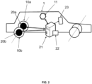
- Said measuring means 20 thus advantageously consist of a steering wheel angular sensor (said at least one quantity representative of an angular speed of the vehicle 1 is the angle of the steering wheel relative to a reference position in which the vehicle 1 is traveling in a straight line), and/or at least two odometers 20a, 20b, i.e. the vehicle 1 has at least two wheels 10a, 10b each equipped with an odometer 20a, 20b (the quantities representative of an angular speed of the vehicle 1 are the speeds of each of the wheels 10a, 10b equipped with an odometer 20a, 20b).
- the vehicle 1 comprises a gyrometer 11 and at least two odometers 20a, 20b each for a wheel 10a, 10b of the vehicle 1.
- wheels of the vehicle 1 may not be equipped with odometers 20a, 20b.
- the two rear wheels 10a, 10b of the vehicle 1 are equipped with odometers 20a, 20b (respectively for the left rear wheel 10a, and the right rear wheel) and the two front wheels are not equipped with them.
- odometers 20a, 20b respectively for the left rear wheel 10a, and the right rear wheel
- the two front wheels are not equipped with them.
- the rear wheels do not rotate around a vertical axis like the front wheels, ie they remain perfectly parallel and at a constant distance.
- the rear wheels are non-driven, and therefore skid less.
- the two front wheels can be taken alternately (this example will also be described, as we will see the front wheels are no longer exactly parallel to each other when the steering wheel is turned, but it is possible to calculate the impact), or a front wheel and a rear wheel, or even three or four wheels.
- the person skilled in the art will know how to use Ackermann's directional geometry for this purpose.
- vehicle 1 is not necessarily a car and can be any vehicle with any number of wheels (including more than four as in a truck).
- An odometer is a device capable of measuring the speed of a wheel by counting the revolutions (“rev counter”) or by measuring the curvilinear abscissa.
- odometers typically have a part fixed to the wheel (for example a magnet), and detect each passage of this fixed part (called a “top”) so as to count the number of revolutions per unit of time, which is the rotation frequency.
- Other techniques are known, for example the optical detection of a mark on the wheel, or the magnetometer of the patent FR2939514 which detects the rotation of an object containing metallic elements.
- the odometers 20a, 20b are directly capable of providing the speeds of the wheels 10a, 10b, or they just indicate the "tops" and it is a processing unit 21 which will be described later which deduces the speeds therefrom.
- the vehicle 1 is further equipped with the gyrometer 11 (typically integral with the bodywork, and generally fixed in the frame of reference of the vehicle 1), i.e. inertial measurement means capable of measuring the angular speed of the vehicle 1 according to a system of three orthogonal axes, which define the vehicle frame of reference.
- the gyrometer 11 typically integral with the bodywork, and generally fixed in the frame of reference of the vehicle 1
- inertial measurement means capable of measuring the angular speed of the vehicle 1 according to a system of three orthogonal axes, which define the vehicle frame of reference.
- Rotation about a vertical axis is described by the angle at which the driver acts by turning the steering wheel.
- the changes in direction of the vehicle are in the horizontal plane, i.e. also along said vertical axis.
- non-zero values for roll (rotation about the longitudinal axis of vehicle 1) and pitch (rotation about the transverse axis of vehicle 1) can be the result of, for example, a sloping road.
- the treatment of these angles can become important when estimating the motion; on the other hand, rotation about the vertical axis of the vehicle is exactly what differential odometry provides as a measure in the ideal.
- ⁇ the vertical component of the angular velocity vector.
- ⁇ the vertical component of the angular velocity vector.
- the angular velocity is positive for a counterclockwise turn (“turn right”) and negative for a clockwise turn (“turn left”).
- the vehicle 1 may be equipped with other gyrometers along other axes and/or accelerometers, or even include an inertial unit with at least three accelerometers and three gyrometers arranged in a triaxial arrangement.
- the accelerometers are sensitive to external forces other than gravitational forces applied to the sensor, and make it possible to measure a specific acceleration noted ⁇ .
- the vehicle 1 further comprises, as explained, processing means 21 (typically a processor) for the direct implementation in real time of the processing of the present method, for example an on-board computer of the vehicle 1, and possibly a memory 22, and an interface 23 for restoring information on the movement of the vehicle 1 to the driver (a instantaneous speed value, a heading, a position on a map, etc.), and/or send commands to the vehicle 1.
- processing means 21 typically a processor
- the vehicle 1 may in this respect be in particular an autonomous vehicle, and the processing means 21 configured to implement the autonomous navigation of the vehicle 1.
- said commands are sent to the vehicle control organs (engine, steering wheel actuators, etc.) so as to simulate driving by the driver.
- the gyrometer 11 and the measuring means 20 are connected to the data processing means 21 in particular by wire, for example via Ethernet.
- Vehicle 1 may optionally include additional sensors such as a GNSS receiver, etc.
- the present method is a method for calibrating at least the gyrometer 11.
- calibration we mean the determination of one or more calibration parameters, a list of which will be seen later.
- certain calibration parameters can be considered reliable, and predetermined. With regard to those to be determined, it can be expected that they have “current” values, and that these values will be modified if necessary.
- the method may further be a method of calibrating the measuring means 20 (the odometers 20a, 20b), i.e. the gyrometer 11 and the odometers 20a, 20b may be calibrated simultaneously.
- the measuring means 20 the odometers 20a, 20b
- the gyrometer 11 and the odometers 20a, 20b may be calibrated simultaneously.
- the present method is even a method for estimating the movement of the vehicle 1, i.e. it includes following the calibration the use of the measurements to reliably deduce one or more components of the movement.
- step (a) the method comprises the acquisition by the gyrometer 11 of a measured angular speed of the vehicle 1, noted ⁇ gyro measure , and by the measuring means 20 of so-called measured values of the at least one quantity representative of the angular speed of the vehicle 1.
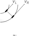
- step (a) more precisely comprises the acquisition by the odometers 20a, 20b of measured speeds of said wheels 10a, 10b. In the preferred example of a left wheel 10a and a right wheel 10b, these speeds are denoted v L and v R .
- angular velocity of vehicle 1 we mean as explained at least that around its vertical axis, but we can also consider those along other axes.
- the data processing means 21 determine the values of at least one calibration parameter of the gyrometer 11 minimizing a difference between a first second estimated angular speed of the vehicle 1 and a second estimated angular speed of the vehicle 1.
- the idea is to estimate in different ways, in particular using different data, the angular velocity. Ideally, the two estimates coincide, otherwise the sensors need to be recalibrated.
- step (b) is implemented recurrently to regularly recalibrate the gyrometer 11.
- D is a scale factor and b a bias.
- D is predetermined (it varies very slowly in practice) and that the only calibration parameter to be determined for the gyrometer 11 is b, which actually tends to vary over time (we speak of drift of the gyrometer 11).
- ⁇ gyro estimate g ⁇ gyro measure with g a function (application) which is not necessarily affine.
- the second estimated angular velocity of vehicle 1, denoted ⁇ smell estimate is derived from the other type of measurement, in particular odometry. In the odometric embodiment, it is a function of the measured speeds of the wheels 10a, 10b and of calibration parameters of the odometers 20a, 20b and, possibly, of the geometric parameters of the vehicle which are not part of the calibration parameters.
- the calibration parameters of the odometers are physical parameters of the vehicle 1.
- odometers there may be additional odometers whose measurements are not considered at this stage.
- three wheels may have odometers, and the measurements of only two used in step (b), while the measurements of the third wheel's odometer may be used separately, see below.
- ⁇ smell estimate ⁇ R v R ⁇ ⁇ L v L d
- ⁇ R , ⁇ L and d are the calibration parameters of the gyrometer 11.
- ⁇ R there are only three calibration parameters to be determined: ⁇ R , ⁇ L and b .
- This limited number of parameters makes such dual calibration possible as soon as the vehicle 1 has a “varied” trajectory (directions/speeds that vary as a function of time). This is useful in particularly in the case of deformations and defects of the tires depending on high speeds and/or accelerations, cf. US4788645 .
- the object minimized in step (b) is the gap ⁇ smell estimate ⁇ ⁇ gyro estimate , which translates into the preferred model as ⁇ R v R ⁇ ⁇ L v L d ⁇ D ⁇ ⁇ gyro measure + b . Minimizing this expression will give the unambiguous parameters for a generic trajectory. It will be understood, however, that alternatively the person skilled in the art may use any other functional sensitive to deviations between ⁇ smell estimate And ⁇ gyro estimate (norm L 2 , L ⁇ , etc).
- the data processing means 21 can work over time on an interval of a given length.
- a recursive filter (RLS methods, recursive least squares, etc.) or an optimization (least squares method, etc.) can be used.
- the method further comprises a step (c) of estimating a parameter representative of an error on the calibration parameters (of the gyrometer 11).
- Step (c) is preferably implemented after each occurrence of step (b).
- the idea is to estimate the quality of the information provided by the measuring means 20 to rule out cases that are unfavorable to calibration, i.e. in which the data from the means 20 are not reliable, such as cases of skidding, excessive movement of the chassis due to excessive acceleration (e.g. braking or sharp turning), or a significant geometric defect (e.g. deflation of a tire).
- a comparison of said parameter with a threshold is implemented.
- step (b) did not take place under favorable conditions and the result of the calibration is not accepted.
- the parameters of the old calibration are then kept as calibration. It is also possible to reject temporarily the measurements of the means 20 (i.e. the odometric measurements).
- step (c) comprises the effective calibration of the gyrometer 11 and, optionally, of the measuring means 20 of said at least one quantity representative of the angular speed of the vehicle 1 with the values determined in step (b) of the calibration parameters.
- determined values of the calibration parameters during an occurrence of step (b), but not used for the actual calibration can be stored on the data storage means 12, and used, either during a future occurrence of step (c). For example, it can be provided that as long as the parameter representative of an error is above the threshold, the determined calibration parameters are stored, and when it goes below the threshold, the actual calibration also takes into account the stored values.
- regime we mean a characterization of the movements of the vehicle 1.
- time intervals with very strong dynamics are typical of very tight turns or speed bumps, and generally of skidding situations or movements of the body of the vehicle 1 relative to the chassis in which the odometric measurements are likely not to be appropriate.
- less strong but varied dynamics linear accelerations and turns which on the one hand are sufficiently light so that the impact of the movement of the chassis remains negligible or modelable with sufficient precision but which on the other hand are sufficiently pronounced to facilitate the calibration of the scale factors and not only of the bias of the gyrometer 11
- linear accelerations and turns which on the one hand are sufficiently light so that the impact of the movement of the chassis remains negligible or modelable with sufficient precision but which on the other hand are sufficiently pronounced to facilitate the calibration of the scale factors and not only of the bias of the gyrometer 11
- said parameter representative of an error on the calibration parameters is a function of at least said second estimated angular speed, calculated for the determined values of the calibration parameters, and of a “reference” angular speed illustrating a comparison element, which according to a first embodiment, not claimed, is the value of the first angular speed (the gyrometric angular speed).
- step (c) is called intrinsic since it only uses quantities available in step (b).
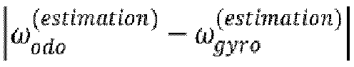
- the estimation residues of step (b) are used, i.e. in the odometric case, said parameter representing an error is in particular the norm (e.g. L 2 , or L ⁇ ) of ⁇ smell estimate ⁇ ⁇ gyro estimate over a given time interval.
- step (c) can be implemented concomitantly with step (b).
- the norm e.g. L 2 or L ⁇
- a person skilled in the art will be able to calculate, on the basis of one or other of these quantities, a reference angular speed, so as to compare it with the second estimated angular speed.
- step (a) comprises for at least one additional wheel equipped with an odometer, the acquisition by this odometer of a measured speed of the additional wheel, so as to obtain a third estimated angular speed.
- learning can be used to improve the estimation of this error parameter and/or develop an approach to identifying the favorable regime in a more robust manner and with increased availability.
- a learning base can be enriched in which each set of measurement data (describing the speed of vehicle 1) is "tagged" with the corresponding value of the parameter representing an error, so as to progressively (as and when steps (b) and (c) are successively occurring) and automatically learn to distinguish acceptable calibrations from unacceptable ones.
- the calibration improves itself continuously.
- the method advantageously comprises a step (d) of estimation by the data processing means 21 of the movement of said vehicle 1 as a function of the measured angular speed of the vehicle 1 and/or the measured values of said at least one quantity representative of the angular speed of the vehicle 1 (the measured speeds of said wheels 10a, 10b), and of the values of the calibration parameters, updated or not according to the result of step (c), i.e. after effective recalibration if necessary.
- Step (d) can be implemented continuously.
- estimation of the movement we mean in particular at least the estimation of an orientation of the vehicle 1 (in the horizontal plane, i.e. a heading, it should be noted that it can be assumed that the horizontal plane of the vehicle substantially coincides with the terrestrial horizontal plane, or at least that the person skilled in the art will be able to detect and correct a possible deviation between these two planes) and advantageously the estimation of a speed standard.
- the orientation is typically obtained by integrating the angular speed.
- the estimation by the data processing means 21 of the heading of said vehicle 1 is made solely as a function of the speed. measured angular speed of the vehicle 1 and the values of the calibration parameters.
- information of another type odometric
- the measured speeds of said wheels 10a, 10b i.e. the odometric data
- step (d) only to determine an overall speed of the vehicle 1, in particular by averaging them.
- Step (d) may further comprise calculating as a function of said parameter representative of an error on the calibration parameters of a gyrometric error in orientation (heading). For example, the heading error accumulated during a period after a calibration may be estimated by the uncertainty in the bias estimation multiplied by the duration of this period.
- step (d) may comprise the generation of a command for said vehicle 1 based on the estimated movement, so as to bring the vehicle 1, for example, to a desired destination, or to stop the vehicle 1 while keeping it on a trajectory free of obstacles.
- the vehicle 1 may further comprise a memory 22 and an interface 23.
- the data processing means 21 are configured to estimate a parameter representative of an error on the calibration parameters, and can also be configured to estimate a movement of said vehicle 1 as a function of the measured angular speed of the vehicle 1 and/or the measured speeds of said wheels 10a, 10b (where appropriate according to the result of a comparison of said parameter representative of an error with a threshold), and the values of the calibration parameters.
- the invention relates to a computer program product comprising code instructions for the execution (on the processing means 21) of a method for calibrating a gyrometer 11 according to the first aspect of the invention, as well as storage means readable by computer equipment (for example data storage means 22) on which this computer program product is found.
Landscapes
- Engineering & Computer Science (AREA)
- Radar, Positioning & Navigation (AREA)
- Remote Sensing (AREA)
- Physics & Mathematics (AREA)
- General Physics & Mathematics (AREA)
- Manufacturing & Machinery (AREA)
- Automation & Control Theory (AREA)
- Gyroscopes (AREA)
- Navigation (AREA)
- Control Of Driving Devices And Active Controlling Of Vehicle (AREA)
Claims (13)
- Verfahren zur Kalibrierung eines in einem Fahrzeug (1) eingebauten Gyrometers (11), wobei das Verfahren dadurch gekennzeichnet ist, dass es die folgenden Schritte umfasst:(a) Erfassen- durch das Gyrometer (11) einer gemessenen Winkelgeschwindigkeit des Fahrzeugs (1),- durch erste Messmittel (20) mindestens einer ersten für die Winkelgeschwindigkeit des Fahrzeugs (1) repräsentativen Größe, von gemessenen Werten der mindestens einen ersten für die Winkelgeschwindigkeit des Fahrzeugs (1) repräsentativen ersten Größe;- durch zweite Messmittel mindestens einer zweiten für die Winkelgeschwindigkeit des Fahrzeugs (1) repräsentativen Größe, die von der mindestens einen ersten für die Winkelgeschwindigkeit des Fahrzeugs (1) repräsentativen Größe unterschiedlich ist, von gemessenen Werten der mindestens einen zweiten für die Winkelgeschwindigkeit des Fahrzeugs (1) repräsentativen zweiten Größe;(b) Bestimmen, durch Datenverarbeitungsmittel (21) von Werten mindestens eines Kalibrierungsparameters des Gyrometers (11), die eine Abweichung zwischen einer ersten geschätzten Winkelgeschwindigkeit des Fahrzeugs (1) und einer zweiten geschätzten Winkelgeschwindigkeit des Fahrzeugs (1) minimiert,- wobei die erste geschätzte Winkelgeschwindigkeit des Fahrzeugs (1) Funktion der gemessenen Winkelgeschwindigkeit und von Kalibrierungsparametern des Gyrometers (11) ist, und- wobei die zweite geschätzte Winkelgeschwindigkeit des Fahrzeugs (1) Funktion der gemessenen Werte der mindestens einen ersten für die Winkelgeschwindigkeit des Fahrzeugs (1) repräsentativen Größe ist;(c) Schätzen eines Parameters, der für einen Fehler in dem oder den Kalibrierungsparametern repräsentativ ist, und, wenn der Parameter, der für einen Fahler in dem oder den Kalibrierungsparametern repräsentativ ist, kleiner als ein vorbestimmter Schwellenwert ist, tatsächliche Kalibrierung des Gyrometers (11) und gegebenenfalls der Messmittel (20) mindestens einer ersten für die Winkelgeschwindigkeit des Fahrzeugs (1) repräsentativen Größe, in Abhängigkeit von den bestimmten Werten der Kalibrierungsparameter, und, wenn der Parameter, der für einen Fehler in dem oder den Kalibrierungsparametern repräsentativ ist, größer als der vorbestimmte Schwellenwert ist, die bestimmten Werte des oder der Kalibrierungsparameter nicht akzeptiert sind,
wobei der Parameter, der für einen Fehler in dem oder den Kalibrierungsparametern repräsentativ ist, aus einem Vergleich zwischen der zweiten geschätzten Winkelgeschwindigkeit und einer Referenzwinkelgeschwindigkeit des Fahrzeugs (1), die abhängig der gemessenen Werte der mindestens einen zweiten für die Winkelgeschwindigkeit des Fahrzeugs (1) repräsentativen Größe ist, resultiert. - Verfahren nach Anspruch 1, wobei die erste geschätzte Winkelgeschwindigkeit


- Verfahren nach einem der Ansprüche 1 und 2, wobei der Schritt (b) die Implementierung eines rekursiven Filters oder einer Optimierung umfasst.
- Verfahren nach einem der Ansprüche 1 bis 3, wobei die ersten Messmittel (20) entweder aus mindestens zwei Wegmessern (20a, 20b) oder aus einem Lenkradwinkelsensor bestehen.
- Verfahren nach Anspruch 4, wobei die ersten Messmittel (20) aus mindestens zwei Wegmessern (20a, 20b) bestehen, wobei das Fahrzeug (1) mindestens zwei Räder (10a, 10b) aufweist, die mit Wegmessern (20a, 20b) versehen sind, wobei die ersten für die Winkelgeschwindigkeit des Fahrzeugs (1) repräsentativen Größen die Geschwindigkeiten der Räder (10a, 10b) sind und die zweite geschätzte Winkelgeschwindigkeit des Fahrzeugs (1) abhängig der gemessenen Geschwindigkeiten der Räder (10a, 10b) und von Kalibrierungsparametern der Wegmesser (20a, 20b) ist.
- Verfahren nach Anspruch 5, wobei der Schritt (b) ebenfalls die Bestimmung von Werten von mindestens einem Kalibrierungsparameter der Wegmesser (20a, 20b) umfasst.
- Verfahren nach einem der Ansprüche 5 und 6, wobei die mindestens zwei mit Wegmessern versehenen Räder (20a, 20b) zwei Hinterräder (10a, 10b) des Fahrzeugs (1) sind, wobei die zweite geschätzte Winkelgeschwindigkeit


- Verfahren nach den Ansprüchen 2, 6 und 7 in Kombination, wobei die Kalibrierungsparameter D und d vorbestimmt sind, wobei der Schritt (b) das Bestimmen der Kalibrierungsparameter b, αR und αL umfasst.
- Verfahren nach einem der Ansprüche 5 bis 8, wobei der Schritt (b) die Minimierung von
- Verfahren nach einem der Ansprüche 5 bis 9, umfassend einen Schritt (d) des Schätzens der Bewegung des Fahrzeugs (1) durch die Datenverarbeitungsmittel (21) in Abhängigkeit von der gemessenen Winkelgeschwindigkeit des Fahrzeugs (1) und/oder den gemessenen Geschwindigkeiten der Räder (10a, 10b) und den Werten der Kalibrierungsparameter, wobei eine Ausrichtung des Fahrzeugs (1) in Schritt (d) nur in Abhängigkeit von der gemessenen Winkelgeschwindigkeit des Fahrzeugs (1) und der Werte der Kalibrierungsparameter geschätzt wird, und die gemessenen Geschwindigkeiten der Räder (10a, 10b) verwendet werden, um eine Gesamtgeschwindigkeit des Fahrzeugs (1) zu schätzen.
- Fahrzeug (1) mit Rädern, umfassend ein Gyrometer (11), das ausgelegt ist, um eine gemessene Winkelgeschwindigkeit des Fahrzeugs (1) zu erfassen, erste Messmittel (20) mindestens einer ersten für die Winkelgeschwindigkeit des Fahrzeugs (1) repräsentativen Größe die ausgelegt sind, um Messwerte der mindestens einen ersten für die Winkelgeschwindigkeit des Fahrzeugs (1) repräsentativen Größe zu erfassen, und zweite Messmittel mindestens einer zweiten für die Winkelgeschwindigkeit des Fahrzeugs (1) repräsentativen Größe, die sich von der mindestens einen ersten für die Winkelgeschwindigkeit des Fahrzeugs (1) repräsentativen Größe unterscheidet, die ausgelegt sind, um Messwerte der mindestens einen zweiten für die Winkelgeschwindigkeit des Fahrzeugs (1) repräsentativen Größe zu erfassen, wobei das Fahrzeug (1) dadurch gekennzeichnet ist, dass es ferner Datenverarbeitungsmittel (21) umfasst, die ausgelegt sind, um Werte von mindestens einem Kalibrierungsparameter des Gyrometers (11) zu bestimmen, die eine Abweichung zwischen einer ersten zweiten geschätzten Winkelgeschwindigkeit des Fahrzeugs (1) und einer zweiten geschätzten Winkelgeschwindigkeit des Fahrzeugs (1) minimieren,- wobei die erste geschätzte Winkelgeschwindigkeit des Fahrzeugs (1) eine Funktion der gemessenen Winkelgeschwindigkeit und von Kalibrierungsparametern des Gyrometers (11) ist, und- wobei die zweite geschätzte Winkelgeschwindigkeit des Fahrzeugs (1) eine Funktion der gemessenen Werte der mindestens einen ersten für die Winkelgeschwindigkeit des Fahrzeugs (1) repräsentativen Größe ist;wobei die Datenverarbeitungsmittel (21) ferner ausgelegt sind, um einen Parameter zu schätzen, der für einen Fehler in dem oder den Kalibrierungsparametern repräsentativ ist, und, wenn der Parameter, der für einen Fehler in dem oder den Kalibrierungsparametern repräsentativ ist, kleiner als ein vorbestimmter Schwellenwert ist, das Gyrometer (11) und gegebenenfalls die Messmittel (20) mindestens einer ersten für die Winkelgeschwindigkeit des Fahrzeugs (1) repräsentativen Größe in Abhängigkeit von den bestimmten Werten der Kalibrierungsparameter zu kalibrieren, und, wenn der Parameter, der für einen Fehler in dem oder den Kalibrierungsparametern repräsentativ ist, größer als der vorbestimmte Schwellenwert ist, die bestimmten Werte des oder der Kalibrierungsparameter nicht zu akzeptieren,wobei der Parameter, der für einen Fehler in dem oder den Kalibrierungsparametern repräsentativ ist, aus einem Vergleich zwischen der zweiten geschätzten Winkelgeschwindigkeit und einer Referenzwinkelgeschwindigkeit des Fahrzeugs (1), die abhängig der gemessenen Werte der mindestens einen zweiten für die Winkelgeschwindigkeit des Fahrzeugs (1) repräsentativen Größe ist, resultiert.
- Rechnerprogrammprodukt, das Codebefehle für die Ausführung eines Verfahrens zur Kalibrierung eines Gyrometers (11) nach einem der Ansprüche 1 bis 10 umfasst, wenn das Programm auf einem Rechner ausgeführt wird.
- Speichermedium, das von einer IT-Ausrüstung lesbar ist, auf dem ein Rechnerprogrammprodukt Codebefehle für die Ausführung eines Verfahrens zur Kalibrierung eines Gyrometers (11) nach einem der Ansprüche 1 bis 10 umfasst.
Applications Claiming Priority (2)
| Application Number | Priority Date | Filing Date | Title |
|---|---|---|---|
| FR1852230A FR3079026B1 (fr) | 2018-03-15 | 2018-03-15 | Procede de calibration d'un gyrometre equipant un vehicule |
| PCT/FR2019/050588 WO2019175516A1 (fr) | 2018-03-15 | 2019-03-15 | Procédé de calibration d'un gyromètre équipant un véhicule |
Publications (3)
| Publication Number | Publication Date |
|---|---|
| EP3765818A1 EP3765818A1 (de) | 2021-01-20 |
| EP3765818B1 true EP3765818B1 (de) | 2024-09-04 |
| EP3765818C0 EP3765818C0 (de) | 2024-09-04 |
Family
ID=62816698
Family Applications (1)
| Application Number | Title | Priority Date | Filing Date |
|---|---|---|---|
| EP19718422.9A Active EP3765818B1 (de) | 2018-03-15 | 2019-03-15 | Verfahren zur kalibrierung eines in einem fahrzeug eingebauten gyrometers |
Country Status (8)
| Country | Link |
|---|---|
| US (1) | US11898872B2 (de) |
| EP (1) | EP3765818B1 (de) |
| JP (1) | JP7344895B2 (de) |
| KR (1) | KR20200130423A (de) |
| CN (1) | CN111902693B (de) |
| ES (1) | ES2994602T3 (de) |
| FR (1) | FR3079026B1 (de) |
| WO (1) | WO2019175516A1 (de) |
Families Citing this family (4)
| Publication number | Priority date | Publication date | Assignee | Title |
|---|---|---|---|---|
| KR20190003918A (ko) * | 2017-06-30 | 2019-01-10 | 현대엠엔소프트 주식회사 | 차량 속도 기반 자이로 센서 캘리브레이션 방법 |
| CN112256035B (zh) * | 2020-11-03 | 2023-08-15 | 浙江国自机器人技术股份有限公司 | 一种底盘漂移控制方法、系统、装置和agv小车 |
| CN114184209B (zh) * | 2021-10-29 | 2023-10-13 | 北京自动化控制设备研究所 | 用于低速检测平台系统的惯性误差抑制方法 |
| CN114323076B (zh) * | 2021-12-31 | 2024-06-21 | 深圳市优必选科技股份有限公司 | 里程计校准方法、装置、机器人和可读存储介质 |
Family Cites Families (30)
| Publication number | Priority date | Publication date | Assignee | Title |
|---|---|---|---|---|
| US4788645A (en) | 1986-03-21 | 1988-11-29 | Etak, Incorporated | Method and apparatus for measuring relative heading changes in a vehicular onboard navigation system |
| JP3018497B2 (ja) * | 1990-11-30 | 2000-03-13 | 住友電気工業株式会社 | 旋回角速度センサのオフセット補正装置 |
| US5416712A (en) * | 1993-05-28 | 1995-05-16 | Trimble Navigation Limited | Position and velocity estimation system for adaptive weighting of GPS and dead-reckoning information |
| JP3422224B2 (ja) * | 1997-07-07 | 2003-06-30 | 三菱自動車工業株式会社 | 車両のヨーレイト演算装置 |
| US6360165B1 (en) * | 1999-10-21 | 2002-03-19 | Visteon Technologies, Llc | Method and apparatus for improving dead reckoning distance calculation in vehicle navigation system |
| JP2008507071A (ja) * | 2004-07-14 | 2008-03-06 | コーニンクレッカ フィリップス エレクトロニクス エヌ ヴィ | 改善されたトラッキングエラー信号の較正方法、及びかかる方法を実現するディスクドライブ |
| DE102004041512A1 (de) * | 2004-08-27 | 2006-03-02 | Robert Bosch Gmbh | Verfahren zur Kalibrierung eines Gyroskops in einem Ortungsmodul in einem beweglichen System |
| JP2006199242A (ja) * | 2005-01-24 | 2006-08-03 | Toyota Motor Corp | 車両の挙動制御装置 |
| DE102005033237B4 (de) * | 2005-07-15 | 2007-09-20 | Siemens Ag | Verfahren zur Bestimmung und Korrektur von Fehlorientierungen und Offsets der Sensoren einer Inertial Measurement Unit in einem Landfahrzeug |
| US7434464B2 (en) * | 2006-09-29 | 2008-10-14 | Freescale Semiconductor, Inc. | Methods and apparatus for a MEMS gyro sensor |
| US7957897B2 (en) * | 2007-06-29 | 2011-06-07 | GM Global Technology Operations LLC | GPS-based in-vehicle sensor calibration algorithm |
| US8195357B2 (en) | 2008-04-16 | 2012-06-05 | GM Global Technology Operations LLC | In-vehicle sensor-based calibration algorithm for yaw rate sensor calibration |
| JP5245531B2 (ja) * | 2008-05-15 | 2013-07-24 | 富士通株式会社 | 角速度検出装置、角速度検出方法、及び、角速度検出プログラム |
| FR2939514B1 (fr) | 2008-12-09 | 2011-02-04 | Sysnav | Dispositif et procede pour determiner la vitesse d'un vehicule terrestre a roues a partir de mesures d'un champ magnetique. |
| US8096179B2 (en) * | 2009-04-09 | 2012-01-17 | Freescale Semiconductor, Inc. | Sensor device with reduced parasitic-induced error |
| DE102009003217A1 (de) * | 2009-05-19 | 2010-11-25 | Robert Bosch Gmbh | Selbsttest für Drehratensensoren |
| JP5746695B2 (ja) * | 2010-06-29 | 2015-07-08 | 本田技研工業株式会社 | 車両の進行路推定装置 |
| US8843290B2 (en) * | 2010-07-22 | 2014-09-23 | Qualcomm Incorporated | Apparatus and methods for calibrating dynamic parameters of a vehicle navigation system |
| CN101915586A (zh) * | 2010-07-22 | 2010-12-15 | 北京全路通信信号研究设计院 | 一种轨道车辆测速测距系统及方法 |
| WO2012062339A1 (en) * | 2010-11-08 | 2012-05-18 | Elektrobit Automotive Gmbh | Technique for calibrating dead reckoning positioning data |
| US8548671B2 (en) * | 2011-06-06 | 2013-10-01 | Crown Equipment Limited | Method and apparatus for automatically calibrating vehicle parameters |
| US20130047726A1 (en) * | 2011-08-26 | 2013-02-28 | Freescale Semiconductor, Inc. | Angular rate sensor with different gap sizes |
| US8965691B1 (en) | 2012-10-05 | 2015-02-24 | Google Inc. | Position and direction determination using multiple single-channel encoders |
| JP5956914B2 (ja) * | 2012-11-14 | 2016-07-27 | Kddi株式会社 | ジャイロセンサの較正機能を備えた角速度測定装置、較正プログラム及び方法 |
| CN103344259B (zh) * | 2013-07-11 | 2016-01-20 | 北京航空航天大学 | 一种基于杆臂估计的ins/gps组合导航系统反馈校正方法 |
| CN104048663A (zh) * | 2014-04-25 | 2014-09-17 | 惠州华阳通用电子有限公司 | 一种车载惯性导航系统及导航方法 |
| US9891245B2 (en) * | 2015-06-29 | 2018-02-13 | CloudNav Inc. | Real-time accelerometer calibration |
| CN105203098B (zh) * | 2015-10-13 | 2018-10-02 | 上海华测导航技术股份有限公司 | 基于九轴mems传感器的农业机械全姿态角更新方法 |
| DE102016201900B4 (de) * | 2016-02-09 | 2024-05-29 | Dialog Semiconductor B.V. | Kalibrierung von Vektoren in einem Messsystem |
| IL249050B (en) * | 2016-11-17 | 2018-03-29 | Elbit Systems Ltd | Self-calibrating inertial measurement method and system |
-
2018
- 2018-03-15 FR FR1852230A patent/FR3079026B1/fr active Active
-
2019
- 2019-03-15 CN CN201980019333.XA patent/CN111902693B/zh active Active
- 2019-03-15 WO PCT/FR2019/050588 patent/WO2019175516A1/fr not_active Ceased
- 2019-03-15 ES ES19718422T patent/ES2994602T3/es active Active
- 2019-03-15 EP EP19718422.9A patent/EP3765818B1/de active Active
- 2019-03-15 KR KR1020207029377A patent/KR20200130423A/ko active Pending
- 2019-03-15 JP JP2020549022A patent/JP7344895B2/ja active Active
- 2019-03-15 US US16/977,785 patent/US11898872B2/en active Active
Non-Patent Citations (1)
| Title |
|---|
| LGC STANDARDS: "Preparation of Calibration Curves - A Guide to Best Practice", 1 September 2003 (2003-09-01), XP055487209, Retrieved from the Internet <URL:https://www.lgcgroup.com/LGCGroup/media/PDFs/Our%20science/NMI%20landing%20page/Publications%20and%20resources/Guides/Calibration-curve-guide.pdf> [retrieved on 20180622] * |
Also Published As
| Publication number | Publication date |
|---|---|
| JP2021518529A (ja) | 2021-08-02 |
| KR20200130423A (ko) | 2020-11-18 |
| CN111902693A (zh) | 2020-11-06 |
| ES2994602T3 (en) | 2025-01-27 |
| EP3765818A1 (de) | 2021-01-20 |
| CN111902693B (zh) | 2024-07-16 |
| US20210088357A1 (en) | 2021-03-25 |
| JP7344895B2 (ja) | 2023-09-14 |
| FR3079026A1 (fr) | 2019-09-20 |
| FR3079026B1 (fr) | 2021-01-01 |
| US11898872B2 (en) | 2024-02-13 |
| EP3765818C0 (de) | 2024-09-04 |
| WO2019175516A1 (fr) | 2019-09-19 |
Similar Documents
| Publication | Publication Date | Title |
|---|---|---|
| EP3765818B1 (de) | Verfahren zur kalibrierung eines in einem fahrzeug eingebauten gyrometers | |
| EP1819984B1 (de) | Hybrides trägheitsnavigationssystem auf der basis eines kinematischen modells | |
| EP2541200B1 (de) | Navigationsvorrichtung und -verfahren, das aus mehreren fahrzeugfest montierten Hybridnavigationssystemen besteht | |
| EP3807594B1 (de) | Verfahren zum kalibrieren von in einem objekt montierten magnetometern | |
| EP2047345A1 (de) | Verfahren zur bestimmung der fahrgrenzen eines fahrzeugs | |
| EP4153465B1 (de) | Verfahren zur berechnung eines sofortigen geschwindigkeitsvektors eines schienenfahrzeugs und entsprechendes system | |
| EP3388914A1 (de) | Zielverfolgungsverfahren durch eine drohne, entsprechende software, entsprechendes elektronisches system und entsprechende drohne | |
| EP3807595B1 (de) | Verfahren zum kalibrieren eines in einem objekt eingebauten gyrometers | |
| EP4028299B1 (de) | Feststellung von fehlerhaftem radverhalten in einem fahrenden fahrzeug | |
| EP2225535A1 (de) | Verfahren für die unabhängige ausrichtung einer inerten einheit für ein bordinstrument zur montage, etwa in einem flugzeug, und bordinstrument mit derartigem verfahren | |
| FR3060178A1 (fr) | Dispositif electronique de pilotage d'un drone, drone, procede de pilotage et programme d'ordinateur associes | |
| FR2994258A1 (fr) | Procede de compensation d'un signal de capteur d'un vehicule et systeme d'informations appliquant un tel procede | |
| EP2006707B1 (de) | Verfahren zur Ermittlung einer Schutzgrenze mit Kompensation von Berechnungsverzögerungen | |
| FR3092914A1 (fr) | Procédé de détermination de la trajectoire d'un véhicule comprenant quatre roues directrices | |
| FR3014556B1 (fr) | Procede et dispositif d'alignement d'une centrale inertielle | |
| FR3041769A1 (fr) | Procede de geolocalisation | |
| EP1940663A1 (de) | Verfahren zur bestimmung einer langfristigen geschwindigkeitsableitung für ein kraftfahrzeug | |
| EP3294600A1 (de) | Identifizierung von blatt- und turmträgheit eines kraftfahrzeugs |
Legal Events
| Date | Code | Title | Description |
|---|---|---|---|
| STAA | Information on the status of an ep patent application or granted ep patent |
Free format text: STATUS: UNKNOWN |
|
| STAA | Information on the status of an ep patent application or granted ep patent |
Free format text: STATUS: THE INTERNATIONAL PUBLICATION HAS BEEN MADE |
|
| PUAI | Public reference made under article 153(3) epc to a published international application that has entered the european phase |
Free format text: ORIGINAL CODE: 0009012 |
|
| STAA | Information on the status of an ep patent application or granted ep patent |
Free format text: STATUS: REQUEST FOR EXAMINATION WAS MADE |
|
| 17P | Request for examination filed |
Effective date: 20201012 |
|
| AK | Designated contracting states |
Kind code of ref document: A1 Designated state(s): AL AT BE BG CH CY CZ DE DK EE ES FI FR GB GR HR HU IE IS IT LI LT LU LV MC MK MT NL NO PL PT RO RS SE SI SK SM TR |
|
| AX | Request for extension of the european patent |
Extension state: BA ME |
|
| DAV | Request for validation of the european patent (deleted) | ||
| DAX | Request for extension of the european patent (deleted) | ||
| RAP3 | Party data changed (applicant data changed or rights of an application transferred) |
Owner name: SYSNAV |
|
| STAA | Information on the status of an ep patent application or granted ep patent |
Free format text: STATUS: EXAMINATION IS IN PROGRESS |
|
| 17Q | First examination report despatched |
Effective date: 20220221 |
|
| REG | Reference to a national code |
Ref country code: DE Ref legal event code: R079 Free format text: PREVIOUS MAIN CLASS: G01C0019000000 Ipc: G01C0021160000 Ref country code: DE Ref legal event code: R079 Ref document number: 602019058263 Country of ref document: DE Free format text: PREVIOUS MAIN CLASS: G01C0019000000 Ipc: G01C0021160000 |
|
| RIC1 | Information provided on ipc code assigned before grant |
Ipc: G01C 25/00 20060101ALI20240207BHEP Ipc: G01C 22/02 20060101ALI20240207BHEP Ipc: G01C 19/00 20130101ALI20240207BHEP Ipc: G01C 21/16 20060101AFI20240207BHEP |
|
| GRAP | Despatch of communication of intention to grant a patent |
Free format text: ORIGINAL CODE: EPIDOSNIGR1 |
|
| STAA | Information on the status of an ep patent application or granted ep patent |
Free format text: STATUS: GRANT OF PATENT IS INTENDED |
|
| INTG | Intention to grant announced |
Effective date: 20240417 |
|
| GRAS | Grant fee paid |
Free format text: ORIGINAL CODE: EPIDOSNIGR3 |
|
| GRAA | (expected) grant |
Free format text: ORIGINAL CODE: 0009210 |
|
| STAA | Information on the status of an ep patent application or granted ep patent |
Free format text: STATUS: THE PATENT HAS BEEN GRANTED |
|
| AK | Designated contracting states |
Kind code of ref document: B1 Designated state(s): AL AT BE BG CH CY CZ DE DK EE ES FI FR GB GR HR HU IE IS IT LI LT LU LV MC MK MT NL NO PL PT RO RS SE SI SK SM TR |
|
| REG | Reference to a national code |
Ref country code: GB Ref legal event code: FG4D Free format text: NOT ENGLISH |
|
| REG | Reference to a national code |
Ref country code: CH Ref legal event code: EP |
|
| REG | Reference to a national code |
Ref country code: IE Ref legal event code: FG4D Free format text: LANGUAGE OF EP DOCUMENT: FRENCH |
|
| REG | Reference to a national code |
Ref country code: DE Ref legal event code: R096 Ref document number: 602019058263 Country of ref document: DE |
|
| U01 | Request for unitary effect filed |
Effective date: 20240926 |
|
| U07 | Unitary effect registered |
Designated state(s): AT BE BG DE DK EE FI FR IT LT LU LV MT NL PT RO SE SI Effective date: 20241022 |
|
| PG25 | Lapsed in a contracting state [announced via postgrant information from national office to epo] |
Ref country code: NO Free format text: LAPSE BECAUSE OF FAILURE TO SUBMIT A TRANSLATION OF THE DESCRIPTION OR TO PAY THE FEE WITHIN THE PRESCRIBED TIME-LIMIT Effective date: 20241204 |
|
| PG25 | Lapsed in a contracting state [announced via postgrant information from national office to epo] |
Ref country code: GR Free format text: LAPSE BECAUSE OF FAILURE TO SUBMIT A TRANSLATION OF THE DESCRIPTION OR TO PAY THE FEE WITHIN THE PRESCRIBED TIME-LIMIT Effective date: 20241205 Ref country code: PL Free format text: LAPSE BECAUSE OF FAILURE TO SUBMIT A TRANSLATION OF THE DESCRIPTION OR TO PAY THE FEE WITHIN THE PRESCRIBED TIME-LIMIT Effective date: 20240904 |
|
| PG25 | Lapsed in a contracting state [announced via postgrant information from national office to epo] |
Ref country code: HR Free format text: LAPSE BECAUSE OF FAILURE TO SUBMIT A TRANSLATION OF THE DESCRIPTION OR TO PAY THE FEE WITHIN THE PRESCRIBED TIME-LIMIT Effective date: 20240904 |
|
| REG | Reference to a national code |
Ref country code: ES Ref legal event code: FG2A Ref document number: 2994602 Country of ref document: ES Kind code of ref document: T3 Effective date: 20250127 |
|
| PG25 | Lapsed in a contracting state [announced via postgrant information from national office to epo] |
Ref country code: RS Free format text: LAPSE BECAUSE OF FAILURE TO SUBMIT A TRANSLATION OF THE DESCRIPTION OR TO PAY THE FEE WITHIN THE PRESCRIBED TIME-LIMIT Effective date: 20241204 |
|
| PG25 | Lapsed in a contracting state [announced via postgrant information from national office to epo] |
Ref country code: RS Free format text: LAPSE BECAUSE OF FAILURE TO SUBMIT A TRANSLATION OF THE DESCRIPTION OR TO PAY THE FEE WITHIN THE PRESCRIBED TIME-LIMIT Effective date: 20241204 Ref country code: PL Free format text: LAPSE BECAUSE OF FAILURE TO SUBMIT A TRANSLATION OF THE DESCRIPTION OR TO PAY THE FEE WITHIN THE PRESCRIBED TIME-LIMIT Effective date: 20240904 Ref country code: NO Free format text: LAPSE BECAUSE OF FAILURE TO SUBMIT A TRANSLATION OF THE DESCRIPTION OR TO PAY THE FEE WITHIN THE PRESCRIBED TIME-LIMIT Effective date: 20241204 Ref country code: HR Free format text: LAPSE BECAUSE OF FAILURE TO SUBMIT A TRANSLATION OF THE DESCRIPTION OR TO PAY THE FEE WITHIN THE PRESCRIBED TIME-LIMIT Effective date: 20240904 Ref country code: GR Free format text: LAPSE BECAUSE OF FAILURE TO SUBMIT A TRANSLATION OF THE DESCRIPTION OR TO PAY THE FEE WITHIN THE PRESCRIBED TIME-LIMIT Effective date: 20241205 |
|
| U20 | Renewal fee for the european patent with unitary effect paid |
Year of fee payment: 7 Effective date: 20250211 |
|
| PG25 | Lapsed in a contracting state [announced via postgrant information from national office to epo] |
Ref country code: IS Free format text: LAPSE BECAUSE OF FAILURE TO SUBMIT A TRANSLATION OF THE DESCRIPTION OR TO PAY THE FEE WITHIN THE PRESCRIBED TIME-LIMIT Effective date: 20250104 |
|
| PG25 | Lapsed in a contracting state [announced via postgrant information from national office to epo] |
Ref country code: SM Free format text: LAPSE BECAUSE OF FAILURE TO SUBMIT A TRANSLATION OF THE DESCRIPTION OR TO PAY THE FEE WITHIN THE PRESCRIBED TIME-LIMIT Effective date: 20240904 |
|
| PG25 | Lapsed in a contracting state [announced via postgrant information from national office to epo] |
Ref country code: CZ Free format text: LAPSE BECAUSE OF FAILURE TO SUBMIT A TRANSLATION OF THE DESCRIPTION OR TO PAY THE FEE WITHIN THE PRESCRIBED TIME-LIMIT Effective date: 20240904 |
|
| PG25 | Lapsed in a contracting state [announced via postgrant information from national office to epo] |
Ref country code: SK Free format text: LAPSE BECAUSE OF FAILURE TO SUBMIT A TRANSLATION OF THE DESCRIPTION OR TO PAY THE FEE WITHIN THE PRESCRIBED TIME-LIMIT Effective date: 20240904 |
|
| PGFP | Annual fee paid to national office [announced via postgrant information from national office to epo] |
Ref country code: GB Payment date: 20250324 Year of fee payment: 7 |
|
| PGFP | Annual fee paid to national office [announced via postgrant information from national office to epo] |
Ref country code: ES Payment date: 20250410 Year of fee payment: 7 |
|
| PLBE | No opposition filed within time limit |
Free format text: ORIGINAL CODE: 0009261 |
|
| STAA | Information on the status of an ep patent application or granted ep patent |
Free format text: STATUS: NO OPPOSITION FILED WITHIN TIME LIMIT |
|
| 26N | No opposition filed |
Effective date: 20250605 |
|
| PG25 | Lapsed in a contracting state [announced via postgrant information from national office to epo] |
Ref country code: MC Free format text: LAPSE BECAUSE OF FAILURE TO SUBMIT A TRANSLATION OF THE DESCRIPTION OR TO PAY THE FEE WITHIN THE PRESCRIBED TIME-LIMIT Effective date: 20240904 |
|
| REG | Reference to a national code |
Ref country code: CH Ref legal event code: H13 Free format text: ST27 STATUS EVENT CODE: U-0-0-H10-H13 (AS PROVIDED BY THE NATIONAL OFFICE) Effective date: 20251024 |