EP3764841B1 - Frame for a table - Google Patents
Frame for a table Download PDFInfo
- Publication number
- EP3764841B1 EP3764841B1 EP19724735.6A EP19724735A EP3764841B1 EP 3764841 B1 EP3764841 B1 EP 3764841B1 EP 19724735 A EP19724735 A EP 19724735A EP 3764841 B1 EP3764841 B1 EP 3764841B1
- Authority
- EP
- European Patent Office
- Prior art keywords
- longitudinal member
- frame according
- engagement
- motor unit
- housing
- Prior art date
- Legal status (The legal status is an assumption and is not a legal conclusion. Google has not performed a legal analysis and makes no representation as to the accuracy of the status listed.)
- Active
Links
Images






Classifications
-
- A—HUMAN NECESSITIES
- A47—FURNITURE; DOMESTIC ARTICLES OR APPLIANCES; COFFEE MILLS; SPICE MILLS; SUCTION CLEANERS IN GENERAL
- A47B—TABLES; DESKS; OFFICE FURNITURE; CABINETS; DRAWERS; GENERAL DETAILS OF FURNITURE
- A47B9/00—Tables with tops of variable height
- A47B9/20—Telescopic guides
-
- A—HUMAN NECESSITIES
- A47—FURNITURE; DOMESTIC ARTICLES OR APPLIANCES; COFFEE MILLS; SPICE MILLS; SUCTION CLEANERS IN GENERAL
- A47B—TABLES; DESKS; OFFICE FURNITURE; CABINETS; DRAWERS; GENERAL DETAILS OF FURNITURE
- A47B9/00—Tables with tops of variable height
- A47B9/04—Tables with tops of variable height with vertical spindle
-
- A—HUMAN NECESSITIES
- A47—FURNITURE; DOMESTIC ARTICLES OR APPLIANCES; COFFEE MILLS; SPICE MILLS; SUCTION CLEANERS IN GENERAL
- A47B—TABLES; DESKS; OFFICE FURNITURE; CABINETS; DRAWERS; GENERAL DETAILS OF FURNITURE
- A47B13/00—Details of tables or desks
- A47B13/02—Underframes
- A47B13/06—Underframes of metal
-
- A—HUMAN NECESSITIES
- A47—FURNITURE; DOMESTIC ARTICLES OR APPLIANCES; COFFEE MILLS; SPICE MILLS; SUCTION CLEANERS IN GENERAL
- A47B—TABLES; DESKS; OFFICE FURNITURE; CABINETS; DRAWERS; GENERAL DETAILS OF FURNITURE
- A47B21/00—Tables or desks for office equipment, e.g. typewriters, keyboards
- A47B21/02—Tables or desks for office equipment, e.g. typewriters, keyboards with vertical adjustable parts
-
- A—HUMAN NECESSITIES
- A47—FURNITURE; DOMESTIC ARTICLES OR APPLIANCES; COFFEE MILLS; SPICE MILLS; SUCTION CLEANERS IN GENERAL
- A47B—TABLES; DESKS; OFFICE FURNITURE; CABINETS; DRAWERS; GENERAL DETAILS OF FURNITURE
- A47B3/00—Folding or stowable tables
- A47B3/08—Folding or stowable tables with legs pivoted to top or underframe
- A47B3/0809—Folding or stowable tables with legs pivoted to top or underframe with elastic locking means
-
- A—HUMAN NECESSITIES
- A47—FURNITURE; DOMESTIC ARTICLES OR APPLIANCES; COFFEE MILLS; SPICE MILLS; SUCTION CLEANERS IN GENERAL
- A47B—TABLES; DESKS; OFFICE FURNITURE; CABINETS; DRAWERS; GENERAL DETAILS OF FURNITURE
- A47B3/00—Folding or stowable tables
- A47B3/08—Folding or stowable tables with legs pivoted to top or underframe
- A47B3/0809—Folding or stowable tables with legs pivoted to top or underframe with elastic locking means
- A47B3/0812—Folding or stowable tables with legs pivoted to top or underframe with elastic locking means the resilient force of the elastic locking means acting in a direction parallel to the axis of rotation of the leg
-
- A—HUMAN NECESSITIES
- A47—FURNITURE; DOMESTIC ARTICLES OR APPLIANCES; COFFEE MILLS; SPICE MILLS; SUCTION CLEANERS IN GENERAL
- A47B—TABLES; DESKS; OFFICE FURNITURE; CABINETS; DRAWERS; GENERAL DETAILS OF FURNITURE
- A47B1/00—Extensible tables
- A47B1/08—Extensible tables with extensible frames or with additional legs
-
- A—HUMAN NECESSITIES
- A47—FURNITURE; DOMESTIC ARTICLES OR APPLIANCES; COFFEE MILLS; SPICE MILLS; SUCTION CLEANERS IN GENERAL
- A47B—TABLES; DESKS; OFFICE FURNITURE; CABINETS; DRAWERS; GENERAL DETAILS OF FURNITURE
- A47B13/00—Details of tables or desks
- A47B13/003—Connecting table tops to underframes
-
- A—HUMAN NECESSITIES
- A47—FURNITURE; DOMESTIC ARTICLES OR APPLIANCES; COFFEE MILLS; SPICE MILLS; SUCTION CLEANERS IN GENERAL
- A47B—TABLES; DESKS; OFFICE FURNITURE; CABINETS; DRAWERS; GENERAL DETAILS OF FURNITURE
- A47B3/00—Folding or stowable tables
- A47B3/08—Folding or stowable tables with legs pivoted to top or underframe
- A47B2003/0824—Folding or stowable tables with legs pivoted to top or underframe the table legs being individually collapsible against the underside of the table top
-
- A—HUMAN NECESSITIES
- A47—FURNITURE; DOMESTIC ARTICLES OR APPLIANCES; COFFEE MILLS; SPICE MILLS; SUCTION CLEANERS IN GENERAL
- A47B—TABLES; DESKS; OFFICE FURNITURE; CABINETS; DRAWERS; GENERAL DETAILS OF FURNITURE
- A47B9/00—Tables with tops of variable height
- A47B9/04—Tables with tops of variable height with vertical spindle
- A47B2009/043—Tables with tops of variable height with vertical spindle with means connecting the spindles of the various legs
-
- A—HUMAN NECESSITIES
- A47—FURNITURE; DOMESTIC ARTICLES OR APPLIANCES; COFFEE MILLS; SPICE MILLS; SUCTION CLEANERS IN GENERAL
- A47B—TABLES; DESKS; OFFICE FURNITURE; CABINETS; DRAWERS; GENERAL DETAILS OF FURNITURE
- A47B2200/00—General construction of tables or desks
- A47B2200/0011—Underframes
- A47B2200/0013—Desks with central bearing beams
-
- A—HUMAN NECESSITIES
- A47—FURNITURE; DOMESTIC ARTICLES OR APPLIANCES; COFFEE MILLS; SPICE MILLS; SUCTION CLEANERS IN GENERAL
- A47B—TABLES; DESKS; OFFICE FURNITURE; CABINETS; DRAWERS; GENERAL DETAILS OF FURNITURE
- A47B2200/00—General construction of tables or desks
- A47B2200/0035—Tables or desks with features relating to adjustability or folding
- A47B2200/005—Leg adjustment
- A47B2200/0051—Telescopic
-
- A—HUMAN NECESSITIES
- A47—FURNITURE; DOMESTIC ARTICLES OR APPLIANCES; COFFEE MILLS; SPICE MILLS; SUCTION CLEANERS IN GENERAL
- A47B—TABLES; DESKS; OFFICE FURNITURE; CABINETS; DRAWERS; GENERAL DETAILS OF FURNITURE
- A47B2200/00—General construction of tables or desks
- A47B2200/0035—Tables or desks with features relating to adjustability or folding
- A47B2200/005—Leg adjustment
- A47B2200/0051—Telescopic
- A47B2200/0054—Telescopic with three telescopic parts
-
- A—HUMAN NECESSITIES
- A47—FURNITURE; DOMESTIC ARTICLES OR APPLIANCES; COFFEE MILLS; SPICE MILLS; SUCTION CLEANERS IN GENERAL
- A47B—TABLES; DESKS; OFFICE FURNITURE; CABINETS; DRAWERS; GENERAL DETAILS OF FURNITURE
- A47B2200/00—General construction of tables or desks
- A47B2200/0035—Tables or desks with features relating to adjustability or folding
- A47B2200/005—Leg adjustment
- A47B2200/0056—Leg adjustment with a motor, e.g. an electric motor
- A47B2200/0057—Leg adjustment with a motor, e.g. an electric motor situated under the worktop
Definitions
- the present invention relates to a frame for sit-stand-tables comprising a cross member, two height-adjustable legs with at least two telescopic profiles, namely an outer and inner profile and having a drive mechanism driven by a motor unit comprising an electric motor and a gear.
- the invention further relates to a height-adjustable table having such a frame.
- Lifting columns comprising a telescopic guide and a box-shaped housing for height-adjustable tables where the telescopic guide appears as a table leg were developed in the late 1990s.
- the box-shaped housing which is usually rectangular, comprises an electric motor, a transmission and various electronics.
- An example of such a lifting column is disclosed in Fig. 1 of WO 2004/100632 A1 to LINAK A/S .
- a different type of lifting column is described in WO 03/003876 A1 to LINAK A/S , where the entire drive unit, i.e. electric motor, transmission and various electronics are integrated in the telescopic guide.
- Another example is disclosed in DE 10 2015 105588 A .
- a frame for a height-adjustable table which comprises an upper frame, which typically comprises two longitudinal members and two cross members, at least one lifting column and at least one foot.
- the lifting column can, as described above, be constructed with or without a box-shaped housing at the upper end.
- the longitudinal members are usually constructed as through-going tube profiles, located in parallel with a mutual distance corresponding to the width of the box-shaped housing.
- At each end of the longitudinal members a cross member is secured.
- the longitudinal members and the cross members are usually welded together or have to be assembled with screws.
- a lifting column is mounted at each end by placing the box-shaped housing between the longitudinal members with an end against the respective cross member. The lifting column is secured by means of screws through the two longitudinal members and through the cross member into the box-shaped housing.
- FIG. 1 An example of such a table is shown in Fig. 1 of US 6,509,705 B2 to LINAK A/S. Assembly of the frame is troublesome and time consuming. This is due to the parts of the frame being relatively large and heavy. Furthermore, the assembly of the frame requires a number of screw operations, which requires that the individual parts are placed correctly relative to each other.
- the leg When the cams are in place in the slits, the leg is turned into a vertical position during which the slanting portion engages the spring-loaded pawl and presses this away from the slanting portions, and when the pawls during the raising of the leg are free of the slanting portion and reaches the area below the slanting portions, the spring loaded pawls will snap back over the slanting portions and thus prevent the slanting portions from moving backwards, thus retaining the leg in the raised position.
- This mounting is not straightforward and moreover the joint is subject to a great deal of play due to the "hinging" in one side which can make the table appear unstable.
- US 2017/0303679 A1 to Timotion discloses a frame comprising a longitudinal member with a height-adjustable leg at each end, which through the respective drive shafts are driven by a motor unit located in the longitudinal member.
- a motor unit located in the longitudinal member.
- DE 30 49 357 A1 to Horn GmbH likewise discloses a frame where the height-adjustable legs are driven by a motor located in the middle of the frame and where the motor has a through-going shaft extending to the two legs.
- the purpose of the invention is to provide a frame for tables, which can be assembled in a simple and non-time-consuming manner.
- the common motor unit is arranged in the longitudinal member and connected to the drive mechanism in the height-adjustable legs, where a mounting bracket for mounting the leg to the longitudinal member is secured to the upper end of the profile, where for mounting of the legs on the longitudinal member, this is equipped with a pair of axle journals on its outer side for cooperation with a pair of recesses at the end of the mounting bracket which faces towards the center of the longitudinal member, and where the outer side of the longitudinal member is equipped with a pair of pins which cooperate with a pair of tracks in the mounting bracket.
- a frame having a simplified construction is achieved.
- the construction of the legs can be simplified and the dimensions reduced as it is not necessary to take the building-in of a motor into the legs into consideration.
- the electrical control may also be simplified as it will not have to drive two motors synchronously.
- the mounting bracket eases the mounting as the legs equipped with mounting brackets are immediately ready for mounting.
- the leg is mounted, it is held in an angular position such that its mounting bracket with the recesses is guided over the two axle journals on the outer side of the longitudinal member, after which the leg is turned to a vertical position.
- With the pair of pins of the of the longitudinal member cooperating with the pair of tracks in the mounting bracket a further fixation of the legs is provided.
- the axle pins and the cooperating recesses at the end of the mounting bracket lock against movement in the vertical direction while the pins and the cooperating tracks from the upper edge of the mounting bracket retains this against movement in the axial direction of the longitudinal member.
- the mounting bracket is U-shaped and has an internal cross section which corresponds to the outer cross section of the longitudinal member, such that this can rest therein.
- the U-shaped bracket contributes to stabilizing the shape of the longitudinal member. This especially applies when the U-shaped bracket with the side walls is fitted in a close-fitting manner over the sides of the longitudinal member.
- the respective ends of the longitudinal member are equipped with a pawl unit and, in the side walls of the mounting bracket, two slits are constructed intended for engagement with the two pawls which protrude out from the side walls in the longitudinal member.
- the pawl unit comprises a housing, the outer shape of which corresponds to the internal shape of the longitudinal member. Two pawls are embedded in the housing, said pawls protrude through a fissure in each side of the housing, and the two pawls are spring-loaded by a coil spring mounted between the two pawls.
- the pawl unit can thus as a separate unit be mounted in the longitudinal member.
- the housing of the pawl unit is secured not only with the two pawls but also with a cam on each side of the housing, which when mounted are positioned in recesses intended for that purpose in the side walls of the longitudinal member.
- the longitudinal member is constituted by a middle section and two end sections, which are longitudinally displaceably embedded in the middle section.
- the length of the longitudinal member can in a simple manner be adapted to the length of the present table top, preferably by symmetric displacement of the two end sections.
- the side walls are terminated in a protruding flange, which is bend to form a groove, and where the end sections likewise have a U-shaped cross section which fits into the middle section, and where the side walls are terminated in a protruding flange, which fits into the groove in the middle section.
- This contributes to a stable shape of the longitudinal member as a whole and further provides a stable guiding of the end sections.
- the side walls of the U-shaped bracket are constructed such that they with the upper edge rest against the lower edge of the protruding flanges on each side of the longitudinal member, this further contributes to increasing the stability of the joining of the legs with the longitudinal member.
- a cross member is secured to the free ends of the two end sections of the longitudinal member, said cross member having a side wall, the height of which corresponds to the height of the longitudinal member, and at the top, the side wall continues as a protruding flange, which is level with the flanges of the longitudinal member.
- the cross member is equipped with a bracket at the lower edge, said bracket has a perpendicular portion protruding from the lower end of the cross member, which at its free edge is terminated in a perpendicular flange.
- the bracket can be screwed or welded on but is expediently constructed as one with the cross member.
- a particularly safe mounting of the cross member can be achieved without the use of tools as the cross member can be mounted onto the longitudinal member by inserting the perpendicular flange on the bracket into a cross slit intended for that purpose in the bottom of the longitudinal member, while the slits in the side wall of the cross member grips over protruding flanges intended for that purpose in the side walls of the longitudinal member.
- the motor unit is mounted in the longitudinal member and is in driving connection with the driving mechanisms of the height-adjustable legs.
- the motor unit comprises a housing with a cover, which as a rule eases the mounting of the motor unit in the longitudinal member.
- the housing is divided into two chambers, one for the motor unit and another for an electrical control, which comprises a printed circuit board, among other things with a mains socket which is accessible through a hole in the side of the longitudinal member, and separate from the mains socket are at least two low voltage sockets, which are accessible through a hole in the other side of the longitudinal member.
- the housing can in that respect be made from a synthetic material, such that the electrical part becomes isolated from the cross member, which is typically bent from metal plates.
- this comprises an electric motor and a gear in the form of a worm gear with a worm in extension of the motor shaft and in engagement with a worm wheel, and where the side of the worm wheel is furnished with one part of the spline coupling for cooperating with the other part of the spline coupling arranged on the driving mechanism of the legs.
- the motor unit is connected to a drive shaft which runs through the longitudinal member to at least one of the legs.
- the motor unit is expediently placed above one of the legs, such that the leg immediately can be connected to the motor unit, by which only one drive shaft is needed, i.e. only one drive shaft will have to be adjusted to the length of the longitudinal member.
- a toothed wheel is mounted to the end of the drive shaft, said toothed wheel is in engagement with the worm wheel of the motor unit, and the opposite end of the drive shaft is in engagement with a corresponding worm gear, where the end of the drive shaft is in engagement with the worm, which further is in engagement with the worm wheel, which through a spline coupling is in engagement with the drive unit of the leg.
- the same gear can thus be used in both the drive shaft and the motor unit, thus keeping the number of components down.
- the drive shaft is telescopic, such that this in a corresponding manner as the longitudinal member can be adapted to the present length of a given table.
- the drive shaft can thus be premounted in the longitudinal member and automatically adapted by adapting the longitudinal member to the desired length.
- the drive shaft consists of three parts, where the two parts, which are in engagement with the motor unit and the gear at the other end of the longitudinal member, respectively, are tubes, while the middle section is a solid rod, which with the ends is received in the two tube portions, and that the cross section is multi-edged such that the rotation from the motor can be transferred to the drive unit for the leg at the other end of the longitudinal member.
- the invention further relates to a height-adjustable table comprising a frame according to one or more of the claims 1-15.
- the height-adjustable table shown in fig. 18 comprises a table top 1 and a frame 2 on which the table top is mounted.
- the frame comprises a length-adjustable longitudinal member 3, two cross members 4,5, one mounted to each end of the longitudinal member, a pair of height-adjustable legs 6,7, also called lifting columns, which with an upper end are mounted to the longitudinal member at either end thereof, and two feet 8,9, one mounted to a lower end of each height-adjustable leg.
- the longitudinal member 3 is constituted by a middle section 3a and two end sections 3b,3c, which are longitudinal displaceably mounted in the middle section 3a for adaption of the length of the longitudinal member to the actual length of the table top.
- the middle section 3a has a U-shaped cross section, where the side walls 10 terminate in an outwardly extending flange 11 which is folded to form a groove 12.
- the two displaceable end sections 3b,3c also have a U-shaped cross section fitting into the middle section 3a and where the side walls 13 terminate in an outwardly extending flange 14 fitting into the groove in the middle section, see figs. 2 and 4 .
- cross member 4,5 To the free ends of the two end sections 3b,3c of the longitudinal member a cross member 4,5 is secured, said cross member 4,5 has a side wall 15, the height of which corresponds to the height of the longitudinal member 3. At the top, the side wall extends into a protruding flange 16, which is level with the flanges 14 of the longitudinal member 3. At the lower edge, the cross member has a bracket 17 with a perpendicular portion 17a protruding from the lower end of the cross member, which at its free edge is terminated in a perpendicular flange 17b.
- the side wall of the cross member has a slit 18,19 at either side of the bracket.
- the cross member 4,5 is mounted on the longitudinal member 3 by inserting the perpendicular flange 17b into a cross slit 20 intended for that purpose in the bottom of the longitudinal member 3, while the slits 18,19 in the side wall 15 of the cross member grip over protruding flanges 21,22 intended for that purpose in the side walls of the longitudinal member 3, see fig. 10 .
- a pawl unit 23 is mounted which comprises a housing 24, the outer shape of which corresponds to the internal shape of the longitudinal member.
- Two pawls 25a,25b are embedded in the housing 24, said pawls 25a,25b protrude through a fissure 26a,26b in each side of the housing.
- the two pawls are spring-loaded by a coil spring 27, mounted between the two pawls.
- a recess 28a,28b in each side for the two pawls.
- the two pawls When the housing 24 with the two pawls is inserted into the longitudinal member 3, the two pawls will automatically, due to the pre-tensioning of the spring be pressed out through the two fissures in the side of the longitudinal member.
- the housing 24 is further retained by a cam 29a,29b on each side of the housing, said cams will, when mounted, rest in recesses 30a,30b in the side walls of the longitudinal member intended for that purpose, see figs. 5-8 .
- the height-adjustable legs 6,7 comprise three telescopic profiles, namely an outer profile 6a, an intermediate profile 6b and an inner profile 6c, where the lower end of the outer profile has a bottom part with screw holes for mounting of a foot 8,9.
- a mounting bracket 31 for mounting of the leg to the longitudinal profile is secured to the upper end.
- the mounting bracket 31 has a U-shaped cross section and has an internal cross section corresponding to the outer cross section of the longitudinal member 3, such that this can rest therein.
- For mounting of the longitudinal member 3 this is on the outer side equipped with a pair of axle journals 32a,32b for cooperating with a pair of recesses 33a,33b intended for that purpose located at the end of the mounting bracket 31 of the leg facing towards the center of the longitudinal member 3.
- the leg 6 When the leg 6 is mounted, this is held in a horizontal position against the longitudinal member 3, see fig. 12 , such that its mounting bracket with the recesses 33a,33b is placed over the two axle journals 32a,32b on the outer side of the longitudinal member 3.
- the external side of the longitudinal member is equipped with a pair of journals 34a,34b for cooperating with a pair of tracks 35a,35b in the mounting bracket 30, said tracks run from the upper edge of the mounting bracket.
- the axle journals 32a,32b and the cooperating recesses 33a,33b in the end of the mounting bracket 30 lock the leg against movement in the vertical direction, while the journals 34a,34b and the cooperating tracks 35a,35b from the upper edge of the mounting bracket retains this against movement in the axial direction of the longitudinal member 3.
- the mounting bracket is locked at the front end by means of the pawl unit 23 at the end of the longitudinal member as two slits 36a,36b, intended for engagement with the two pawls 25a,25b which protrude from the side walls in the longitudinal member, are constructed in the sidewalls of the mounting bracket 30.
- the securing of the leg is as a rule stabilized in that the U-shaped bracket 30 with the side walls is is fitted in a close-fitting manner over the side of the longitudinal member 3 and in addition, the upper edge of the U-shaped bracket 30 rests against the lower edge of the protruding flanges 14 on each side of the longitudinal member 3b.
- the legs 6,7 also called lifting columns, are equipped with a driving mechanism in the form of a spindle unit comprising a solid spindle and a hollow spindle as well as a drive tube.
- the spindle unit is with its one side secured to the outer tube and with the other end secured to the inner profile, while the intermediate profile is secured to the hollow spindle such that it is guided synchronously with the inner profile.
- a pin 37a of a spline coupling is secured to the upper end of the drive tube.
- a hole 38 is constructed, which the spline coupling pin protrudes through, see fig. 12 .
- a motor unit 39 is mounted, which comprises a housing 40 with a cover 41, see fig. 13 .
- the housing is divided into two chambers 40a,40b, one for the motor unit 39 and another for the electrical control, which comprises a printed circuit board 42, among other things with a mains socket 43 which is accessible through a hole in the side of the longitudinal member 3.
- a mains socket 43 which is accessible through a hole in the side of the longitudinal member 3.
- two low voltage sockets 44 Separate from the mains socket are two low voltage sockets 44, which are accessible through a hole in the other side of the longitudinal member.
- the motor unit 39 comprises an electric motor 45 and a gear 46 in the form of a worm gear with a worm in extension of the motor shaft and in engagement with a worm wheel.
- the other part of the spline coupling is constructed, i.e. a recess 37b for receiving the spline coupling pin 37a, see fig. 12 .
- the motor unit is connected to a drive shaft 47 which runs through the longitudinal member 3 to the other leg 7, see fig. 1 .
- a toothed wheel is mounted, which is in engagement with the worm wheel of the motor unit.
- the drive shaft 47 is in engagement with a corresponding worm gear 48, where the end of the drive shaft is in engagement with the worm, which further is in engagement with the worm wheel, which through a spline coupling is in engagement with the drive unit of the legs 5.
- the drive shaft 47 is telescopic, such that this in a corresponding manner as the longitudinal member 3 can be adapted to the present length of a given table.
- the drive shaft 47 consists of three parts, where the two parts 47b,47c, which are in engagement with the motor unit 39 and the gear 48 at the other end of the longitudinal member, respectively, are tubes, while the middle section 47a is a solid rod, which with the ends is received in the two tube portions 47b,47c.
- the cross section is multi-edged such that the rotation from the motor can be transferred to the drive unit for the leg at the other end of the longitudinal member.
- the drive mechanism for bringing about the telescopic movement of the legs comprises a spindle unit, consisting of a solid spindle and a hollow spindle both having external threads.
- a spindle nut for the solid spindle is secured, said spindle nut is constructed as a bushing with internal threads.
- the hollow spindle is surrounded by a drive tube furnished with a number of axially running grooves on its inner side.
- a ring is secured to the external side thereof, said ring having a number of fins on its outer side, which protrude into the grooves of the drive tube.
- a support tube surrounds the drive tube and at the lower end of the support tube a spindle nut for the hollow spindle is secured.
- the spindle nut is in the shape of a bushing with internal threads.
- the invention is here in particular mentioned in connection with sit-stand desks, but it is understood that the invention can also be used in connection with other types of tables such as work tables, counters, kitchen tables etc.
Landscapes
- Mutual Connection Of Rods And Tubes (AREA)
- Tables And Desks Characterized By Structural Shape (AREA)
- Rehabilitation Tools (AREA)
- Accommodation For Nursing Or Treatment Tables (AREA)
- Legs For Furniture In General (AREA)
Description
- The present invention relates to a frame for sit-stand-tables comprising a cross member, two height-adjustable legs with at least two telescopic profiles, namely an outer and inner profile and having a drive mechanism driven by a motor unit comprising an electric motor and a gear. The invention further relates to a height-adjustable table having such a frame.
- Lifting columns comprising a telescopic guide and a box-shaped housing for height-adjustable tables where the telescopic guide appears as a table leg were developed in the late 1990s. The box-shaped housing, which is usually rectangular, comprises an electric motor, a transmission and various electronics. An example of such a lifting column is disclosed in
Fig. 1 ofWO 2004/100632 A1 to LINAK A/S . A different type of lifting column is described inWO 03/003876 A1 to LINAK A/S DE 10 2015 105588 A . - A frame for a height-adjustable table, which comprises an upper frame, which typically comprises two longitudinal members and two cross members, at least one lifting column and at least one foot. The lifting column can, as described above, be constructed with or without a box-shaped housing at the upper end. The longitudinal members are usually constructed as through-going tube profiles, located in parallel with a mutual distance corresponding to the width of the box-shaped housing. At each end of the longitudinal members a cross member is secured. The longitudinal members and the cross members are usually welded together or have to be assembled with screws. A lifting column is mounted at each end by placing the box-shaped housing between the longitudinal members with an end against the respective cross member. The lifting column is secured by means of screws through the two longitudinal members and through the cross member into the box-shaped housing. An example of such a table is shown in
Fig. 1 ofUS 6,509,705 B2 to LINAK A/S. Assembly of the frame is troublesome and time consuming. This is due to the parts of the frame being relatively large and heavy. Furthermore, the assembly of the frame requires a number of screw operations, which requires that the individual parts are placed correctly relative to each other. -
DE 20 2016 002 581 U1 to Kesseböhmer discloses a table with height-adjustable legs having a built-in motor - this type of leg is also known as in-line lifting columns. To the upper end of the leg a plate is secured, which extends a distance over the end of the leg. At one end, the plate is equipped with a protruding cam in each side intended for insertion into a slit in the upper frame. At the opposite end, the plate is in either side equipped with a slanting portion intended for engagement with a spring-loaded pawl mounted in the upper frame and in its longitudinal direction. When mounting, the leg is held in an inclined position by which the cams can be inserted into the respective slits. When the cams are in place in the slits, the leg is turned into a vertical position during which the slanting portion engages the spring-loaded pawl and presses this away from the slanting portions, and when the pawls during the raising of the leg are free of the slanting portion and reaches the area below the slanting portions, the spring loaded pawls will snap back over the slanting portions and thus prevent the slanting portions from moving backwards, thus retaining the leg in the raised position. This mounting is not straightforward and moreover the joint is subject to a great deal of play due to the "hinging" in one side which can make the table appear unstable. -
US 2017/0303679 A1 to Timotion discloses a frame comprising a longitudinal member with a height-adjustable leg at each end, which through the respective drive shafts are driven by a motor unit located in the longitudinal member. Here, it has, however, been necessary to utilize a special coupling for connecting the legs in order to have these run synchronously.DE 30 49 357 A1 to Horn GmbH likewise discloses a frame where the height-adjustable legs are driven by a motor located in the middle of the frame and where the motor has a through-going shaft extending to the two legs. - The purpose of the invention is to provide a frame for tables, which can be assembled in a simple and non-time-consuming manner.
- This is achieved according to the invention in that the common motor unit is arranged in the longitudinal member and connected to the drive mechanism in the height-adjustable legs, where a mounting bracket for mounting the leg to the longitudinal member is secured to the upper end of the profile, where for mounting of the legs on the longitudinal member, this is equipped with a pair of axle journals on its outer side for cooperation with a pair of recesses at the end of the mounting bracket which faces towards the center of the longitudinal member, and where the outer side of the longitudinal member is equipped with a pair of pins which cooperate with a pair of tracks in the mounting bracket.
- Thus, a frame having a simplified construction is achieved. The construction of the legs can be simplified and the dimensions reduced as it is not necessary to take the building-in of a motor into the legs into consideration. As both legs are driven by a common motor unit, the electrical control may also be simplified as it will not have to drive two motors synchronously. The mounting bracket eases the mounting as the legs equipped with mounting brackets are immediately ready for mounting. When the leg is mounted, it is held in an angular position such that its mounting bracket with the recesses is guided over the two axle journals on the outer side of the longitudinal member, after which the leg is turned to a vertical position. With the pair of pins of the of the longitudinal member cooperating with the pair of tracks in the mounting bracket, a further fixation of the legs is provided. Hence, the axle pins and the cooperating recesses at the end of the mounting bracket lock against movement in the vertical direction while the pins and the cooperating tracks from the upper edge of the mounting bracket retains this against movement in the axial direction of the longitudinal member.
- In a special embodiment, the mounting bracket is U-shaped and has an internal cross section which corresponds to the outer cross section of the longitudinal member, such that this can rest therein. As the legs are typically located at the ends of the longitudinal member, the U-shaped bracket contributes to stabilizing the shape of the longitudinal member. This especially applies when the U-shaped bracket with the side walls is fitted in a close-fitting manner over the sides of the longitudinal member.
- In an embodiment of the invention, the respective ends of the longitudinal member are equipped with a pawl unit and, in the side walls of the mounting bracket, two slits are constructed intended for engagement with the two pawls which protrude out from the side walls in the longitudinal member. When the legs with the mounting bracket are placed over the longitudinal member, the two pawls in the pawl mechanism will be pressed back and when the mounting bracket with the two slits is positioned opposite the pawls, they will snap forth and enter into engagement with these. The legs are thus finally locked to the longitudinal member. The vibrations and shaking arising during the use of the table causes the pawls of the pawl unit to "gnaw" themselves further into engagement with the longitudinal member, thus increasing the firmness of the locking of the two parts of the frame. If, for some reason, it should be desired to dismantle the legs, this can be done by pressing the pawls back such that they release their engagement with the slits and tilting the leg backwards.
- In a special embodiment, the pawl unit comprises a housing, the outer shape of which corresponds to the internal shape of the longitudinal member. Two pawls are embedded in the housing, said pawls protrude through a fissure in each side of the housing, and the two pawls are spring-loaded by a coil spring mounted between the two pawls. The pawl unit can thus as a separate unit be mounted in the longitudinal member. In an embodiment, the housing of the pawl unit is secured not only with the two pawls but also with a cam on each side of the housing, which when mounted are positioned in recesses intended for that purpose in the side walls of the longitudinal member.
- In an embodiment for the invention, the longitudinal member is constituted by a middle section and two end sections, which are longitudinally displaceably embedded in the middle section. Thus, the length of the longitudinal member can in a simple manner be adapted to the length of the present table top, preferably by symmetric displacement of the two end sections.
- In a special embodiment of the middle section having a U-shaped cross section, the side walls are terminated in a protruding flange, which is bend to form a groove, and where the end sections likewise have a U-shaped cross section which fits into the middle section, and where the side walls are terminated in a protruding flange, which fits into the groove in the middle section. This contributes to a stable shape of the longitudinal member as a whole and further provides a stable guiding of the end sections. As the side walls of the U-shaped bracket are constructed such that they with the upper edge rest against the lower edge of the protruding flanges on each side of the longitudinal member, this further contributes to increasing the stability of the joining of the legs with the longitudinal member.
- In an embodiment of the invention, a cross member is secured to the free ends of the two end sections of the longitudinal member, said cross member having a side wall, the height of which corresponds to the height of the longitudinal member, and at the top, the side wall continues as a protruding flange, which is level with the flanges of the longitudinal member. When the cross members are secured to the table top, it does not only provide stability to the frame, it also supports the long sides of the table top.
- In a special embodiment, the cross member is equipped with a bracket at the lower edge, said bracket has a perpendicular portion protruding from the lower end of the cross member, which at its free edge is terminated in a perpendicular flange. The bracket can be screwed or welded on but is expediently constructed as one with the cross member. In a further embodiment, there is a slit in the side wall of the cross member at either side of the bracket. Thus, a particularly safe mounting of the cross member can be achieved without the use of tools as the cross member can be mounted onto the longitudinal member by inserting the perpendicular flange on the bracket into a cross slit intended for that purpose in the bottom of the longitudinal member, while the slits in the side wall of the cross member grips over protruding flanges intended for that purpose in the side walls of the longitudinal member.
- In an embodiment of the invention, the motor unit is mounted in the longitudinal member and is in driving connection with the driving mechanisms of the height-adjustable legs. In a special embodiment, the motor unit comprises a housing with a cover, which as a rule eases the mounting of the motor unit in the longitudinal member. In a further development of the invention, the housing is divided into two chambers, one for the motor unit and another for an electrical control, which comprises a printed circuit board, among other things with a mains socket which is accessible through a hole in the side of the longitudinal member, and separate from the mains socket are at least two low voltage sockets, which are accessible through a hole in the other side of the longitudinal member. The housing can in that respect be made from a synthetic material, such that the electrical part becomes isolated from the cross member, which is typically bent from metal plates.
- In an embodiment of the motor unit, this comprises an electric motor and a gear in the form of a worm gear with a worm in extension of the motor shaft and in engagement with a worm wheel, and where the side of the worm wheel is furnished with one part of the spline coupling for cooperating with the other part of the spline coupling arranged on the driving mechanism of the legs. This enables an easy joining of the drive unit of the legs and the motor unit, as the two parts of the spline coupling merely will have to be brought into engagement with each other.
- In a further embodiment, the motor unit is connected to a drive shaft which runs through the longitudinal member to at least one of the legs. The motor unit is expediently placed above one of the legs, such that the leg immediately can be connected to the motor unit, by which only one drive shaft is needed, i.e. only one drive shaft will have to be adjusted to the length of the longitudinal member.
- In a special embodiment of the invention, a toothed wheel is mounted to the end of the drive shaft, said toothed wheel is in engagement with the worm wheel of the motor unit, and the opposite end of the drive shaft is in engagement with a corresponding worm gear, where the end of the drive shaft is in engagement with the worm, which further is in engagement with the worm wheel, which through a spline coupling is in engagement with the drive unit of the leg. The same gear can thus be used in both the drive shaft and the motor unit, thus keeping the number of components down.
- In an embodiment, the drive shaft is telescopic, such that this in a corresponding manner as the longitudinal member can be adapted to the present length of a given table. The drive shaft can thus be premounted in the longitudinal member and automatically adapted by adapting the longitudinal member to the desired length. In a special embodiment, the drive shaft consists of three parts, where the two parts, which are in engagement with the motor unit and the gear at the other end of the longitudinal member, respectively, are tubes, while the middle section is a solid rod, which with the ends is received in the two tube portions, and that the cross section is multi-edged such that the rotation from the motor can be transferred to the drive unit for the leg at the other end of the longitudinal member.
- The invention further relates to a height-adjustable table comprising a frame according to one or more of the claims 1-15.
- The invention will be explained more fully below with reference to the embodiment shown in the accompanying drawing. In the drawing,
-
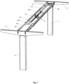
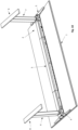
fig. 1 shows a perspective view of an assembled frame seen from above, but shown without feet, -
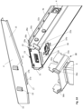
fig. 2 shows an exploded view of one end of the frame shown infig. 1 , -
fig. 3 shows an exploded view of the end of the longitudinal member with the motor unit, -
fig. 4 shows the end of the longitudinal member with mounted legs and shown without crossbar, -
fig. 5 shows the pawl unit seen directly from the side and with the pawls shown in their fully extended position, -
fig. 6 shows an exploded view of the pawl unit, -
fig. 7 shows the pawl unit shown with one side wall removed, -
fig. 8 shows a perspective view of the pawl unit where the pawls are shown retracted, -
fig. 9 shows the longitudinal member mounted to the underside of a table top, -
fig. 10 shows an exploded view of the end of one end of the frame, -
fig. 11 shows the same asfig. 5 , but where the cross members are mounted to the ends of the longitudinal member, -
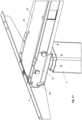
fig. 12 shows a close-up illustration of the end of the longitudinal member shown with a leg ready for mounting to this, -
fig. 13 shows the same asfig. 11 but shown with the legs partially mounted, -
fig. 14 shows a close-up illustration of the end of the leg in the same position as shown infig. 13 , -
fig. 15 shows the same asfig. 14 , but where the longitudinal member for the sake of clarity is shown without cross member, -
fig. 16 shows the same asfig. 13 , but with the legs shown in the fully mounted position, -
fig. 17 shows a close-up illustration of one end of the longitudinal member with cross member and the leg shown in its final mounted position, -
fig. 18 , shows the same asfig. 16 but where the feet are indicated mounted on the lower end of the legs, -
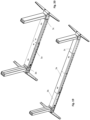
fig. 19 shows the frame in its maximum length, i.e. with the longitudinal member in its maximum extended position, and -
fig. 20 shows the frame in its shortest length, i.e. with the longitudinal member in its fully retracted length. - The height-adjustable table shown in
fig. 18 comprises atable top 1 and aframe 2 on which the table top is mounted. The frame comprises a length-adjustablelongitudinal member 3, twocross members adjustable legs feet - The
longitudinal member 3 is constituted by amiddle section 3a and twoend sections middle section 3a for adaption of the length of the longitudinal member to the actual length of the table top. Themiddle section 3a has a U-shaped cross section, where theside walls 10 terminate in an outwardly extendingflange 11 which is folded to form agroove 12. The twodisplaceable end sections middle section 3a and where theside walls 13 terminate in an outwardly extendingflange 14 fitting into the groove in the middle section, seefigs. 2 and4 . - To the free ends of the two
end sections cross member cross member side wall 15, the height of which corresponds to the height of thelongitudinal member 3. At the top, the side wall extends into a protrudingflange 16, which is level with theflanges 14 of thelongitudinal member 3. At the lower edge, the cross member has abracket 17 with aperpendicular portion 17a protruding from the lower end of the cross member, which at its free edge is terminated in aperpendicular flange 17b. The side wall of the cross member has aslit cross member longitudinal member 3 by inserting theperpendicular flange 17b into a cross slit 20 intended for that purpose in the bottom of thelongitudinal member 3, while theslits side wall 15 of the cross member grip over protrudingflanges longitudinal member 3, seefig. 10 . - At the free end of the
longitudinal member 3 apawl unit 23 is mounted which comprises ahousing 24, the outer shape of which corresponds to the internal shape of the longitudinal member. Twopawls housing 24, saidpawls fissure 26a,26b in each side of the housing. The two pawls are spring-loaded by acoil spring 27, mounted between the two pawls. In the side walls of the longitudinal member there is arecess 28a,28b in each side for the two pawls. When thehousing 24 with the two pawls is inserted into thelongitudinal member 3, the two pawls will automatically, due to the pre-tensioning of the spring be pressed out through the two fissures in the side of the longitudinal member. Thehousing 24 is further retained by acam recesses 30a,30b in the side walls of the longitudinal member intended for that purpose, seefigs. 5-8 . - The height-
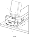
adjustable legs intermediate profile 6b and an inner profile 6c, where the lower end of the outer profile has a bottom part with screw holes for mounting of afoot longitudinal member 3, such that this can rest therein. For mounting of thelongitudinal member 3 this is on the outer side equipped with a pair ofaxle journals recesses 33a,33b intended for that purpose located at the end of the mounting bracket 31 of the leg facing towards the center of thelongitudinal member 3. When theleg 6 is mounted, this is held in a horizontal position against thelongitudinal member 3, seefig. 12 , such that its mounting bracket with therecesses 33a,33b is placed over the twoaxle journals longitudinal member 3. For additional fixation of theleg 6, the external side of the longitudinal member is equipped with a pair ofjournals tracks 35a,35b in the mountingbracket 30, said tracks run from the upper edge of the mounting bracket. Theaxle journals recesses 33a,33b in the end of the mountingbracket 30 lock the leg against movement in the vertical direction, while thejournals tracks 35a,35b from the upper edge of the mounting bracket retains this against movement in the axial direction of thelongitudinal member 3. Finally, the mounting bracket is locked at the front end by means of thepawl unit 23 at the end of the longitudinal member as twoslits pawls bracket 30. Moreover, the securing of the leg is as a rule stabilized in that theU-shaped bracket 30 with the side walls is is fitted in a close-fitting manner over the side of thelongitudinal member 3 and in addition, the upper edge of theU-shaped bracket 30 rests against the lower edge of the protrudingflanges 14 on each side of thelongitudinal member 3b. - The
legs pin 37a of a spline coupling is secured. At the bottom of the longitudinal member ahole 38 is constructed, which the spline coupling pin protrudes through, seefig. 12 . - In the
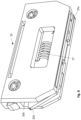
longitudinal member 3, amotor unit 39 is mounted, which comprises ahousing 40 with acover 41, seefig. 13 . The housing is divided into twochambers motor unit 39 and another for the electrical control, which comprises a printedcircuit board 42, among other things with amains socket 43 which is accessible through a hole in the side of thelongitudinal member 3. Separate from the mains socket are twolow voltage sockets 44, which are accessible through a hole in the other side of the longitudinal member. Themotor unit 39 comprises anelectric motor 45 and agear 46 in the form of a worm gear with a worm in extension of the motor shaft and in engagement with a worm wheel. On the side of the worm wheel, the other part of the spline coupling is constructed, i.e. arecess 37b for receiving thespline coupling pin 37a, seefig. 12 . Moreover, the motor unit is connected to adrive shaft 47 which runs through thelongitudinal member 3 to theother leg 7, seefig. 1 . At the end of the drive shaft, a toothed wheel is mounted, which is in engagement with the worm wheel of the motor unit. At the opposite end, thedrive shaft 47 is in engagement with acorresponding worm gear 48, where the end of the drive shaft is in engagement with the worm, which further is in engagement with the worm wheel, which through a spline coupling is in engagement with the drive unit of thelegs 5. It is noted that thedrive shaft 47 is telescopic, such that this in a corresponding manner as thelongitudinal member 3 can be adapted to the present length of a given table. - The
drive shaft 47 consists of three parts, where the twoparts motor unit 39 and thegear 48 at the other end of the longitudinal member, respectively, are tubes, while themiddle section 47a is a solid rod, which with the ends is received in the twotube portions - The drive mechanism for bringing about the telescopic movement of the legs comprises a spindle unit, consisting of a solid spindle and a hollow spindle both having external threads. At the lower end of the hollow spindle, a spindle nut for the solid spindle is secured, said spindle nut is constructed as a bushing with internal threads. By rotating the hollow spindle, the spindle nut will screw itself up solid spindle as this is retained against rotation at its free end. The hollow spindle is surrounded by a drive tube furnished with a number of axially running grooves on its inner side. At the upper end of the hollow spindle, a ring is secured to the external side thereof, said ring having a number of fins on its outer side, which protrude into the grooves of the drive tube. A support tube surrounds the drive tube and at the lower end of the support tube a spindle nut for the hollow spindle is secured. The spindle nut is in the shape of a bushing with internal threads. When the drive tube is rotated, the support tube will screw itself up the hollow spindle as the support tube at its upper end is secured against rotation. As the hollow spindle is driven around, this will screw itself synchronously up the solid spindle, as previously explained, i.e. the axial movement is the joint movement of both the hollow and solid spindle. The drive tube is driven by the motor unit via the spline coupling.
- The invention is here in particular mentioned in connection with sit-stand desks, but it is understood that the invention can also be used in connection with other types of tables such as work tables, counters, kitchen tables etc.
Claims (16)
- A frame for sit-stand-tables comprising a longitudinal member (3), two height-adjustable legs (6,7) with at least two telescopic profiles, namely an outer and an inner profile, and with a driving mechanism, driven by a common motor unit (39), comprising an electric motor (45) and a gear (46), where the common motor unit is arranged in the longitudinal member (3) and connected to the driving mechanism in the height-adjustable legs (6,7), where a mounting bracket (31) for mounting the leg (6,7) to the longitudinal member (3) is secured to the upper end of the profile, where the external side of the longitudinal member (3) is equipped with a pair of axle journals (32a,32b) for cooperating with a pair of recesses (33a,33b) located at the end of the mounting bracket (31) of the leg (6,7) facing towards the center of the longitudinal member (3), wherein the external side of the longitudinal member (3) is equipped with a pair of journals (34a,34b) cooperating with a pair of tracks (35a,35b) in the mounting bracket (31), said tracks extending from the upper edge of the mounting bracket.
- A frame according to claim 1, characterized in that the mounting bracket (31) is U-shaped and has an internal cross section corresponding to the outer cross section of the longitudinal member (3) such that the longitudinal member can rest in this.
- A frame according to one or more of the claims 1-2, characterized in that it comprises a pawl unit (23) arranged at the end of the longitudinal member (3) as the side walls of the mounting bracket (31) are constructed with two grooves (36a,36b) intended for engagement with the two pawls (35a,35b) protruding from the side walls of the longitudinal member (3).
- A frame according to claim 3 characterized in that the pawl unit (23) comprises a housing (24), the external shape of which corresponds to the internal shape of the cross member (3), and that two pawls (25a,25b) embedded in the housing protrude through a fissure (26a,26b) in each side of the housing (24), and that the two pawls are spring-loaded by a coil spring (27), mounted between the two pawls.
- A frame according to claim 4, characterized in that the housing (24) of the pawl unit (23), in addition to the two pawls (25a,25b), furthermore is secured by a cam on each side of the housing, said cams (29a,29b) will when mounted rest in recesses (30a,30b) in the side walls of the longitudinal member (3) intended for that purpose.
- A frame according to one or more of the claims 1-4, characterized in that the longitudinal member (3) is constituted by a middle section (3a) and two end sections (3b,3c), which are mounted longitudinal displaceable in the middle section.
- A frame according to claim 6, characterized in that the middle section (3a) has a U-shaped cross section, where the side walls (10) terminate in an outwardly extending flange (11) which is folded to form a groove (12), and where the end sections (3b,3c) also have a U-shaped cross section fitting into the middle section (3a) and where the side walls terminate in an outwardly extending flange (14) fitting into the groove (12) in the middle section (3a).
- A frame according to one of the claims 1-7, characterized in that the common motor unit (39) is mounted in the longitudinal member (3) and is in driving connection with the driving mechanisms of the height-adjustable legs (6,7).
- A frame according to claim 8, characterized in that the common motor unit (39) comprises a housing (40) with a cover (41).
- A frame according to claim 9, characterized in that the housing (40) is divided into two chambers (40a,40b), one for the common motor unit (39) and another for the electric control, which comprises a printed circuit board (42), among other things comprising a mains socket (43), which is accessible through a hole in the side of the longitudinal member (3), and separate from the mains socket (43) there is at least one low voltage socket (44), which is accessible through a hole in the other side of the longitudinal member (3).
- A frame according to claim 8, characterized in that the common motor unit (39) comprises an electric motor (45) and a gear (46) in the form of a worm gear having a worm in continuation of the motor shaft and in engagement with a worm wheel, and where the side of the worm wheel is furnished with one part (37b) of a spline connection for cooperating with the other part (37a) of the spline connection arranged on the driving mechanism of the legs (6,7).
- A frame according to claim 8, characterized in that the common motor unit (39) is in connection with a drive shaft (47) running through the longitudinal member (3) to at least one of the legs (6,7).
- A frame according to claim 12,
characterized in that a toothed wheel is mounted on the end of the drive shaft, said toothed wheel is in engagement with the worm wheel of the common motor unit (39), and that the opposite end of the drive shaft is in connection with a corresponding worm gear (48) where the end of the drive shaft is in engagement with the worm which further is in engagement with the worm wheel which through a spline coupling is in engagement with the driving unit of the leg (7). - A frame according to claim 12,
characterized in that the drive shaft (47) is constructed telescopic such that this in a corresponding manner as the longitudinal member (3) can be adapted to the current length of a given table. - A frame according to claim 12,
characterized in that the drive shaft (47) is constituted by three parts, where the two parts (47b,47c), which are in engagement with the common motor unit (39) and the gear (48), respectively, in the other side of the longitudinal member, are tubes, while the middle section (47a) is a solid rod, which with the ends is received in the two tubes (47b,47c), and that the cross section is polygonal, such that the rotation from the motor (45) can be transferred to the drive unit for the leg (7) at the other side of the longitudinal member (3). - Height-adjustable table comprising a frame according to one or more of the claims 1-15.
Applications Claiming Priority (2)
| Application Number | Priority Date | Filing Date | Title |
|---|---|---|---|
| DKPA201800117 | 2018-03-14 | ||
| PCT/DK2019/000094 WO2019174686A2 (en) | 2018-03-14 | 2019-03-13 | Frame for a table |
Publications (2)
| Publication Number | Publication Date |
|---|---|
| EP3764841A2 EP3764841A2 (en) | 2021-01-20 |
| EP3764841B1 true EP3764841B1 (en) | 2024-12-25 |
Family
ID=66589154
Family Applications (1)
| Application Number | Title | Priority Date | Filing Date |
|---|---|---|---|
| EP19724735.6A Active EP3764841B1 (en) | 2018-03-14 | 2019-03-13 | Frame for a table |
Country Status (7)
| Country | Link |
|---|---|
| US (2) | US11357320B2 (en) |
| EP (1) | EP3764841B1 (en) |
| JP (1) | JP7397799B2 (en) |
| CN (1) | CN111867425B (en) |
| CA (1) | CA3092777A1 (en) |
| DK (1) | DK3764841T3 (en) |
| WO (1) | WO2019174686A2 (en) |
Cited By (1)
| Publication number | Priority date | Publication date | Assignee | Title |
|---|---|---|---|---|
| DE102025113436A1 (en) | 2025-04-04 | 2026-04-30 | Kesseböhmer Holding Kg | Support frame of a piece of furniture, furniture with such a support frame and method for securing and unlocking a folding column of the support frame |
Families Citing this family (29)
| Publication number | Priority date | Publication date | Assignee | Title |
|---|---|---|---|---|
| US11096481B2 (en) * | 2017-07-28 | 2021-08-24 | Varidesk, Llc | Motorized adjustable height table |
| DK3764841T3 (en) * | 2018-03-14 | 2025-03-31 | Linak As | Table frame |
| CN112074210B (en) | 2018-05-04 | 2021-11-16 | 珀品有限公司 | Attachment components for tool-less installation |
| CN111436746B (en) * | 2020-04-23 | 2024-11-12 | 常州市凯迪电器股份有限公司 | A quick-assembled desktop stand |
| CN111920181B (en) * | 2020-07-21 | 2025-12-23 | 常州市凯迪电器股份有限公司 | Modular linear actuators and height-adjustable tables |
| DE102020211087A1 (en) | 2020-09-02 | 2022-03-03 | Veyhl Gmbh | table frame and table |
| DE202020105069U1 (en) | 2020-09-02 | 2021-12-03 | Veyhl Gmbh | table frame and table |
| CN213820289U (en) * | 2020-11-10 | 2021-07-30 | 德沃康科技集团有限公司 | A folding table frame and folding table |
| CN112741415A (en) * | 2021-01-19 | 2021-05-04 | 宁波汇五洲智能科技有限公司 | Lifting table convenient to disassemble and assemble |
| US11419410B1 (en) * | 2021-02-05 | 2022-08-23 | Shanghai Tengfei Communication Equipment Industry Co., Ltd | Lifting table |
| CN112815044A (en) * | 2021-02-07 | 2021-05-18 | 德沃康科技集团有限公司 | One-electric two-drive synchronous driving device |
| USD943324S1 (en) * | 2021-04-12 | 2022-02-15 | Kanuodisi (Guangzhou) Furniture Co., Ltd. | Desk frame |
| TWM618980U (en) * | 2021-05-28 | 2021-11-01 | 第一傳動科技股份有限公司 | Lightweight electric table stand |
| US11490726B1 (en) * | 2021-07-01 | 2022-11-08 | Zhejiang Jiecang Linear Motion Technology Co., Ltd. | Folding table stand, folding table, and method for assembling the same |
| TWM622096U (en) * | 2021-07-21 | 2022-01-11 | 第一傳動科技股份有限公司 | Lifting table stand |
| EP4173520A1 (en) * | 2021-10-26 | 2023-05-03 | Actiforce International B.V. | Height-adjustable office furniture |
| CN217390195U (en) * | 2021-11-10 | 2022-09-09 | 常州市凯迪电器股份有限公司 | Lifting table support with quick mounting structure and lifting table |
| TWI788178B (en) * | 2022-01-04 | 2022-12-21 | 第一傳動科技股份有限公司 | Power-driven table, power-driven table stand and lightweight beam structure thereof |
| CN217565255U (en) * | 2022-03-01 | 2022-10-14 | 浙江捷昌线性驱动科技股份有限公司 | Electric lifting table |
| US11925265B2 (en) * | 2022-03-30 | 2024-03-12 | Loctek Ergonomic Technology Corp. | Transmission rod assembly and a height-adjustable desk thereof |
| TWI790975B (en) * | 2022-06-06 | 2023-01-21 | 第一傳動科技股份有限公司 | Beam structure of electric table stand |
| CN217851805U (en) | 2022-07-08 | 2022-11-22 | 南通市久正人体工学股份有限公司 | Three-leg electric lifting table |
| CN115153181A (en) * | 2022-08-12 | 2022-10-11 | 南通市久正人体工学股份有限公司 | Electric lifting table |
| US12622510B2 (en) | 2022-08-12 | 2026-05-12 | Qidong Vision Mounts Manufacturing Co., Ltd. | Electric height-adjustable desk |
| CN218791096U (en) | 2022-09-19 | 2023-04-07 | 东莞市诗丹德利五金制造有限责任公司 | Folding lifting table frame |
| CN120882341A (en) * | 2023-02-10 | 2025-10-31 | 诺尔有限公司 | Channel assembly for reducing working surface sag |
| CA3246915A1 (en) * | 2023-04-18 | 2025-07-10 | Workrite Ergonomics, Llc | Table frame with integrated mounting flanges |
| KR102850469B1 (en) * | 2024-06-12 | 2025-08-26 | 주식회사 디자인칼라스 | Desk having wiring arrangement box |
| WO2026067063A1 (en) * | 2024-09-30 | 2026-04-02 | 乐歌人体工学科技股份有限公司 | Table |
Citations (2)
| Publication number | Priority date | Publication date | Assignee | Title |
|---|---|---|---|---|
| DE3049357A1 (en) * | 1980-12-29 | 1982-07-29 | Horn GmbH & Co KG, 7062 Rudersberg | Vertically adjustable table with motorised extending legs - has two guide columns formed by legs at tabletop ends for stable support |
| US9848696B2 (en) * | 2016-04-26 | 2017-12-26 | Powdermet Inc. | Electric table stand, coupling thereof, and electric table with electric table stand |
Family Cites Families (38)
| Publication number | Priority date | Publication date | Assignee | Title |
|---|---|---|---|---|
| JPS60139924U (en) * | 1984-02-27 | 1985-09-17 | コクヨ株式会社 | shaft joint |
| JPH07148023A (en) * | 1993-11-26 | 1995-06-13 | Komura Seisakusho:Kk | table |
| US6182583B1 (en) * | 1997-09-08 | 2001-02-06 | John E. Larson | Height adjustable pedestal for chairs and tables |
| EP1079511A1 (en) * | 1999-08-26 | 2001-02-28 | Linak A/S | Power supply for DC-motors |
| TW453155U (en) * | 2000-10-19 | 2001-09-01 | Kai Jr Entpr Co Ltd | Folding structure of support leg |
| DK1401304T3 (en) | 2001-07-04 | 2007-04-30 | Linak As | Drive device, preferably for lifting columns for height adjustable tables and lifting column |
| CN1784937B (en) | 2003-05-06 | 2011-09-28 | 利纳克有限公司 | An actuator |
| US7908981B2 (en) * | 2007-01-31 | 2011-03-22 | Michael Agee | Height adjustable table |
| NL2001472C2 (en) * | 2008-04-11 | 2009-10-13 | Vehold B V | Adjustment device. |
| EP2160958B1 (en) * | 2008-09-08 | 2016-06-29 | Linak A/S | Height adjustable table |
| SE532213C2 (en) * | 2008-09-24 | 2009-11-17 | Swedestyle Ab | Device for mounting a table top on a rack with drive means |
| EP2290260B1 (en) * | 2009-08-31 | 2012-10-03 | KIH-utveckling AB | Linear actuator comprising an end stop detection unit |
| US8967054B2 (en) * | 2011-06-03 | 2015-03-03 | Kimball International, Inc. | Office desking system |
| US9038549B1 (en) * | 2012-06-01 | 2015-05-26 | Humanscale Corporation | Height adjustable table |
| CN103315519B (en) * | 2013-06-28 | 2015-03-25 | 浙江捷昌线性驱动科技股份有限公司 | Foldable support for lifting table or chair |
| ES2633600T3 (en) * | 2013-11-18 | 2017-09-22 | Usm Holding Ag | Height adjustable leg cabinet |
| TWM486995U (en) * | 2014-04-03 | 2014-10-01 | Timotion Technology Co Ltd | Easy to unfold and fold electric table foot frame |
| EP3148373A1 (en) * | 2014-05-26 | 2017-04-05 | Linak A/S | Height-adjustable supporting frame |
| US10674813B2 (en) * | 2014-05-26 | 2020-06-09 | Linak A/S | Supporting frame for a piece of furniture |
| US10004326B2 (en) | 2014-05-26 | 2018-06-26 | Linak A/S | Supporting frame for a piece of furniture |
| TWM496957U (en) * | 2014-10-23 | 2015-03-11 | Chun-Tsair Wang | Driver fastening apparatus of electric height adjusting desk |
| CH710641B1 (en) * | 2015-01-21 | 2019-07-15 | Licenscom Gmbh | Height-adjustable nail cosmetic work table with integrated dust extraction. |
| DE102015105588A1 (en) | 2015-04-13 | 2016-10-13 | Dewertokin Gmbh | Table frame for a table |
| DE102015105827A1 (en) * | 2015-04-16 | 2016-10-20 | Dewertokin Gmbh | Table frame for a table |
| DE202016002581U1 (en) | 2015-04-30 | 2016-05-09 | Kesseböhmer Produktions GmbH & Co. KG | System for attaching a furniture leg to a furniture |
| DE102015216821B4 (en) * | 2015-09-02 | 2022-02-03 | Kesseböhmer Produktions GmbH & Co. KG | Furniture frame for securing a foldable furniture column |
| US20170071332A1 (en) * | 2015-09-15 | 2017-03-16 | Next Technologies, Inc. | Height Adjustable Desks with Ultraviolet Light Irradiation of Keyboard Tray |
| DE102016101955A1 (en) * | 2016-02-04 | 2017-08-10 | Karsten Laing | Electrically adjustable furniture |
| US9730512B1 (en) * | 2016-02-10 | 2017-08-15 | Veyhl Gmbh | Table frame and table |
| EP3311692A1 (en) * | 2016-10-20 | 2018-04-25 | Vitra Patente AG | Height-adjustable frame with folding leg elements |
| SE1651506A1 (en) | 2016-11-17 | 2018-04-10 | Polstiernan Ind Ab | A collapsible table stand, and a table including such a table stand |
| US10791826B2 (en) * | 2017-03-31 | 2020-10-06 | Twin-Star International, Inc. | Adjustable height desk system |
| US11096481B2 (en) * | 2017-07-28 | 2021-08-24 | Varidesk, Llc | Motorized adjustable height table |
| US20190069669A1 (en) * | 2017-09-01 | 2019-03-07 | David R. Hall | Elliptically Rotating Cable Organizing Device |
| US10842258B2 (en) * | 2017-09-18 | 2020-11-24 | Fellowes, Inc. | Variable height platform system |
| TWI711409B (en) * | 2017-10-26 | 2020-12-01 | 第一傳動科技股份有限公司 | Lifting table stand with easy assembly |
| DE102018104195A1 (en) * | 2018-02-23 | 2019-08-29 | Logicdata Electronic & Software Entwicklungs Gmbh | Furniture, method for calibrating an actuator and method for adjusting a component of a piece of furniture |
| DK3764841T3 (en) * | 2018-03-14 | 2025-03-31 | Linak As | Table frame |
-
2019
- 2019-03-13 DK DK19724735.6T patent/DK3764841T3/en active
- 2019-03-13 EP EP19724735.6A patent/EP3764841B1/en active Active
- 2019-03-13 JP JP2020547199A patent/JP7397799B2/en active Active
- 2019-03-13 WO PCT/DK2019/000094 patent/WO2019174686A2/en not_active Ceased
- 2019-03-13 US US16/977,344 patent/US11357320B2/en active Active
- 2019-03-13 CN CN201980018974.3A patent/CN111867425B/en active Active
- 2019-03-13 CA CA3092777A patent/CA3092777A1/en active Pending
-
2022
- 2022-05-31 US US17/828,403 patent/US11839301B2/en active Active
Patent Citations (2)
| Publication number | Priority date | Publication date | Assignee | Title |
|---|---|---|---|---|
| DE3049357A1 (en) * | 1980-12-29 | 1982-07-29 | Horn GmbH & Co KG, 7062 Rudersberg | Vertically adjustable table with motorised extending legs - has two guide columns formed by legs at tabletop ends for stable support |
| US9848696B2 (en) * | 2016-04-26 | 2017-12-26 | Powdermet Inc. | Electric table stand, coupling thereof, and electric table with electric table stand |
Cited By (1)
| Publication number | Priority date | Publication date | Assignee | Title |
|---|---|---|---|---|
| DE102025113436A1 (en) | 2025-04-04 | 2026-04-30 | Kesseböhmer Holding Kg | Support frame of a piece of furniture, furniture with such a support frame and method for securing and unlocking a folding column of the support frame |
Also Published As
| Publication number | Publication date |
|---|---|
| CN111867425A (en) | 2020-10-30 |
| US11839301B2 (en) | 2023-12-12 |
| DK3764841T3 (en) | 2025-03-31 |
| WO2019174686A3 (en) | 2019-10-24 |
| JP7397799B2 (en) | 2023-12-13 |
| US11357320B2 (en) | 2022-06-14 |
| EP3764841A2 (en) | 2021-01-20 |
| CA3092777A1 (en) | 2019-09-19 |
| CN111867425B (en) | 2023-11-10 |
| US20210100355A1 (en) | 2021-04-08 |
| US20220287452A1 (en) | 2022-09-15 |
| JP2021515653A (en) | 2021-06-24 |
| WO2019174686A2 (en) | 2019-09-19 |
Similar Documents
| Publication | Publication Date | Title |
|---|---|---|
| US11839301B2 (en) | Frame for a table | |
| US10004326B2 (en) | Supporting frame for a piece of furniture | |
| EP3148372B1 (en) | Supporting frame for a piece of furniture | |
| JP5902099B2 (en) | Pull-out guide for drawer | |
| EP1353128B1 (en) | A width adjustable support frame for use in an household appliance, specially in a cooking- and backing oven | |
| EP3769646B1 (en) | Three-section linkage drawer slides apparatus | |
| US20120017414A1 (en) | Cabinet drawer support system | |
| US20120248910A1 (en) | Linear actuator | |
| EP1639926A1 (en) | Coffee apparatus with a height-adustable collecting bowl | |
| WO2015180724A1 (en) | Height-adjustable supporting frame | |
| KR20100012201A (en) | Apparatus for adjusting board angle of table | |
| CN111050603A (en) | Panel Holders and Drawers | |
| JP5252542B2 (en) | A mechanism for changing the support position of an attachment in a bed | |
| KR100881257B1 (en) | Height adjustable bookcase | |
| CN120769717A (en) | Translation-rotation accessories and components of furniture or household appliances | |
| AT412055B (en) | DEVICE FOR FIXING AND RELEASING PROFILES TELESCOPED INTO ANOTHER | |
| WO2002039848A1 (en) | Linear actuator | |
| EP3081112A1 (en) | Device for tilting and locking the resting surface of a table | |
| KR19990008025U (en) | Shelf Support | |
| DE60320472T2 (en) | Substructure for height-adjustable table | |
| AT10095U1 (en) | DEVICE FOR HEIGHT ADJUSTMENT OF A WORKTOP OF A KITCHEN FURNITURE | |
| SE2351396A1 (en) | Underframe and table |
Legal Events
| Date | Code | Title | Description |
|---|---|---|---|
| STAA | Information on the status of an ep patent application or granted ep patent |
Free format text: STATUS: UNKNOWN |
|
| STAA | Information on the status of an ep patent application or granted ep patent |
Free format text: STATUS: THE INTERNATIONAL PUBLICATION HAS BEEN MADE |
|
| PUAI | Public reference made under article 153(3) epc to a published international application that has entered the european phase |
Free format text: ORIGINAL CODE: 0009012 |
|
| STAA | Information on the status of an ep patent application or granted ep patent |
Free format text: STATUS: REQUEST FOR EXAMINATION WAS MADE |
|
| 17P | Request for examination filed |
Effective date: 20201009 |
|
| AK | Designated contracting states |
Kind code of ref document: A2 Designated state(s): AL AT BE BG CH CY CZ DE DK EE ES FI FR GB GR HR HU IE IS IT LI LT LU LV MC MK MT NL NO PL PT RO RS SE SI SK SM TR |
|
| AX | Request for extension of the european patent |
Extension state: BA ME |
|
| DAV | Request for validation of the european patent (deleted) | ||
| DAX | Request for extension of the european patent (deleted) | ||
| RAP3 | Party data changed (applicant data changed or rights of an application transferred) |
Owner name: LINAK A/S |
|
| STAA | Information on the status of an ep patent application or granted ep patent |
Free format text: STATUS: EXAMINATION IS IN PROGRESS |
|
| 17Q | First examination report despatched |
Effective date: 20230222 |
|
| GRAP | Despatch of communication of intention to grant a patent |
Free format text: ORIGINAL CODE: EPIDOSNIGR1 |
|
| STAA | Information on the status of an ep patent application or granted ep patent |
Free format text: STATUS: GRANT OF PATENT IS INTENDED |
|
| INTG | Intention to grant announced |
Effective date: 20240717 |
|
| GRAS | Grant fee paid |
Free format text: ORIGINAL CODE: EPIDOSNIGR3 |
|
| GRAA | (expected) grant |
Free format text: ORIGINAL CODE: 0009210 |
|
| STAA | Information on the status of an ep patent application or granted ep patent |
Free format text: STATUS: THE PATENT HAS BEEN GRANTED |
|
| AK | Designated contracting states |
Kind code of ref document: B1 Designated state(s): AL AT BE BG CH CY CZ DE DK EE ES FI FR GB GR HR HU IE IS IT LI LT LU LV MC MK MT NL NO PL PT RO RS SE SI SK SM TR |
|
| REG | Reference to a national code |
Ref country code: GB Ref legal event code: FG4D |
|
| REG | Reference to a national code |
Ref country code: CH Ref legal event code: EP |
|
| REG | Reference to a national code |
Ref country code: DE Ref legal event code: R096 Ref document number: 602019063934 Country of ref document: DE |
|
| REG | Reference to a national code |
Ref country code: IE Ref legal event code: FG4D |
|
| REG | Reference to a national code |
Ref country code: DK Ref legal event code: T3 Effective date: 20250325 |
|
| REG | Reference to a national code |
Ref country code: SE Ref legal event code: TRGR |
|
| REG | Reference to a national code |
Ref country code: LT Ref legal event code: MG9D |
|
| PG25 | Lapsed in a contracting state [announced via postgrant information from national office to epo] |
Ref country code: FI Free format text: LAPSE BECAUSE OF FAILURE TO SUBMIT A TRANSLATION OF THE DESCRIPTION OR TO PAY THE FEE WITHIN THE PRESCRIBED TIME-LIMIT Effective date: 20241225 |
|
| PG25 | Lapsed in a contracting state [announced via postgrant information from national office to epo] |
Ref country code: BG Free format text: LAPSE BECAUSE OF FAILURE TO SUBMIT A TRANSLATION OF THE DESCRIPTION OR TO PAY THE FEE WITHIN THE PRESCRIBED TIME-LIMIT Effective date: 20241225 |
|
| PG25 | Lapsed in a contracting state [announced via postgrant information from national office to epo] |
Ref country code: NO Free format text: LAPSE BECAUSE OF FAILURE TO SUBMIT A TRANSLATION OF THE DESCRIPTION OR TO PAY THE FEE WITHIN THE PRESCRIBED TIME-LIMIT Effective date: 20250325 |
|
| PG25 | Lapsed in a contracting state [announced via postgrant information from national office to epo] |
Ref country code: GR Free format text: LAPSE BECAUSE OF FAILURE TO SUBMIT A TRANSLATION OF THE DESCRIPTION OR TO PAY THE FEE WITHIN THE PRESCRIBED TIME-LIMIT Effective date: 20250326 Ref country code: LV Free format text: LAPSE BECAUSE OF FAILURE TO SUBMIT A TRANSLATION OF THE DESCRIPTION OR TO PAY THE FEE WITHIN THE PRESCRIBED TIME-LIMIT Effective date: 20241225 |
|
| PG25 | Lapsed in a contracting state [announced via postgrant information from national office to epo] |
Ref country code: RS Free format text: LAPSE BECAUSE OF FAILURE TO SUBMIT A TRANSLATION OF THE DESCRIPTION OR TO PAY THE FEE WITHIN THE PRESCRIBED TIME-LIMIT Effective date: 20250325 |
|
| REG | Reference to a national code |
Ref country code: NL Ref legal event code: MP Effective date: 20241225 |
|
| PG25 | Lapsed in a contracting state [announced via postgrant information from national office to epo] |
Ref country code: NL Free format text: LAPSE BECAUSE OF FAILURE TO SUBMIT A TRANSLATION OF THE DESCRIPTION OR TO PAY THE FEE WITHIN THE PRESCRIBED TIME-LIMIT Effective date: 20241225 |
|
| REG | Reference to a national code |
Ref country code: AT Ref legal event code: MK05 Ref document number: 1753428 Country of ref document: AT Kind code of ref document: T Effective date: 20241225 |
|
| PG25 | Lapsed in a contracting state [announced via postgrant information from national office to epo] |
Ref country code: SM Free format text: LAPSE BECAUSE OF FAILURE TO SUBMIT A TRANSLATION OF THE DESCRIPTION OR TO PAY THE FEE WITHIN THE PRESCRIBED TIME-LIMIT Effective date: 20241225 |
|
| PG25 | Lapsed in a contracting state [announced via postgrant information from national office to epo] |
Ref country code: PL Free format text: LAPSE BECAUSE OF FAILURE TO SUBMIT A TRANSLATION OF THE DESCRIPTION OR TO PAY THE FEE WITHIN THE PRESCRIBED TIME-LIMIT Effective date: 20241225 |
|
| PG25 | Lapsed in a contracting state [announced via postgrant information from national office to epo] |
Ref country code: ES Free format text: LAPSE BECAUSE OF FAILURE TO SUBMIT A TRANSLATION OF THE DESCRIPTION OR TO PAY THE FEE WITHIN THE PRESCRIBED TIME-LIMIT Effective date: 20241225 |
|
| PG25 | Lapsed in a contracting state [announced via postgrant information from national office to epo] |
Ref country code: IS Free format text: LAPSE BECAUSE OF FAILURE TO SUBMIT A TRANSLATION OF THE DESCRIPTION OR TO PAY THE FEE WITHIN THE PRESCRIBED TIME-LIMIT Effective date: 20250425 |
|
| PG25 | Lapsed in a contracting state [announced via postgrant information from national office to epo] |
Ref country code: PT Free format text: LAPSE BECAUSE OF FAILURE TO SUBMIT A TRANSLATION OF THE DESCRIPTION OR TO PAY THE FEE WITHIN THE PRESCRIBED TIME-LIMIT Effective date: 20250428 |
|
| PG25 | Lapsed in a contracting state [announced via postgrant information from national office to epo] |
Ref country code: EE Free format text: LAPSE BECAUSE OF FAILURE TO SUBMIT A TRANSLATION OF THE DESCRIPTION OR TO PAY THE FEE WITHIN THE PRESCRIBED TIME-LIMIT Effective date: 20241225 |
|
| PG25 | Lapsed in a contracting state [announced via postgrant information from national office to epo] |
Ref country code: AT Free format text: LAPSE BECAUSE OF FAILURE TO SUBMIT A TRANSLATION OF THE DESCRIPTION OR TO PAY THE FEE WITHIN THE PRESCRIBED TIME-LIMIT Effective date: 20241225 Ref country code: RO Free format text: LAPSE BECAUSE OF FAILURE TO SUBMIT A TRANSLATION OF THE DESCRIPTION OR TO PAY THE FEE WITHIN THE PRESCRIBED TIME-LIMIT Effective date: 20241225 |
|
| PG25 | Lapsed in a contracting state [announced via postgrant information from national office to epo] |
Ref country code: SK Free format text: LAPSE BECAUSE OF FAILURE TO SUBMIT A TRANSLATION OF THE DESCRIPTION OR TO PAY THE FEE WITHIN THE PRESCRIBED TIME-LIMIT Effective date: 20241225 |
|
| PG25 | Lapsed in a contracting state [announced via postgrant information from national office to epo] |
Ref country code: CZ Free format text: LAPSE BECAUSE OF FAILURE TO SUBMIT A TRANSLATION OF THE DESCRIPTION OR TO PAY THE FEE WITHIN THE PRESCRIBED TIME-LIMIT Effective date: 20241225 |
|
| PG25 | Lapsed in a contracting state [announced via postgrant information from national office to epo] |
Ref country code: IT Free format text: LAPSE BECAUSE OF FAILURE TO SUBMIT A TRANSLATION OF THE DESCRIPTION OR TO PAY THE FEE WITHIN THE PRESCRIBED TIME-LIMIT Effective date: 20241225 |
|
| REG | Reference to a national code |
Ref country code: DE Ref legal event code: R097 Ref document number: 602019063934 Country of ref document: DE |
|
| PG25 | Lapsed in a contracting state [announced via postgrant information from national office to epo] |
Ref country code: MC Free format text: LAPSE BECAUSE OF FAILURE TO SUBMIT A TRANSLATION OF THE DESCRIPTION OR TO PAY THE FEE WITHIN THE PRESCRIBED TIME-LIMIT Effective date: 20241225 |
|
| REG | Reference to a national code |
Ref country code: CH Ref legal event code: H13 Free format text: ST27 STATUS EVENT CODE: U-0-0-H10-H13 (AS PROVIDED BY THE NATIONAL OFFICE) Effective date: 20251023 |
|
| PLBE | No opposition filed within time limit |
Free format text: ORIGINAL CODE: 0009261 |
|
| STAA | Information on the status of an ep patent application or granted ep patent |
Free format text: STATUS: NO OPPOSITION FILED WITHIN TIME LIMIT |
|
| PG25 | Lapsed in a contracting state [announced via postgrant information from national office to epo] |
Ref country code: LU Free format text: LAPSE BECAUSE OF NON-PAYMENT OF DUE FEES Effective date: 20250313 |
|
| GBPC | Gb: european patent ceased through non-payment of renewal fee |
Effective date: 20250325 |
|
| 26N | No opposition filed |
Effective date: 20250926 |
|
| REG | Reference to a national code |
Ref country code: BE Ref legal event code: MM Effective date: 20250331 |
|
| PG25 | Lapsed in a contracting state [announced via postgrant information from national office to epo] |
Ref country code: GB Free format text: LAPSE BECAUSE OF NON-PAYMENT OF DUE FEES Effective date: 20250325 |
|
| PG25 | Lapsed in a contracting state [announced via postgrant information from national office to epo] |
Ref country code: FR Free format text: LAPSE BECAUSE OF NON-PAYMENT OF DUE FEES Effective date: 20250331 |
|
| PG25 | Lapsed in a contracting state [announced via postgrant information from national office to epo] |
Ref country code: BE Free format text: LAPSE BECAUSE OF NON-PAYMENT OF DUE FEES Effective date: 20250331 |
|
| PG25 | Lapsed in a contracting state [announced via postgrant information from national office to epo] |
Ref country code: CH Free format text: LAPSE BECAUSE OF NON-PAYMENT OF DUE FEES Effective date: 20250331 |
|
| PG25 | Lapsed in a contracting state [announced via postgrant information from national office to epo] |
Ref country code: IE Free format text: LAPSE BECAUSE OF NON-PAYMENT OF DUE FEES Effective date: 20250313 |
|
| PGFP | Annual fee paid to national office [announced via postgrant information from national office to epo] |
Ref country code: SE Payment date: 20260319 Year of fee payment: 8 |
|
| PGFP | Annual fee paid to national office [announced via postgrant information from national office to epo] |
Ref country code: DK Payment date: 20260324 Year of fee payment: 8 Ref country code: DE Payment date: 20260319 Year of fee payment: 8 |
|
| PG25 | Lapsed in a contracting state [announced via postgrant information from national office to epo] |
Ref country code: HR Free format text: LAPSE BECAUSE OF FAILURE TO SUBMIT A TRANSLATION OF THE DESCRIPTION OR TO PAY THE FEE WITHIN THE PRESCRIBED TIME-LIMIT Effective date: 20241225 |
|
| PG25 | Lapsed in a contracting state [announced via postgrant information from national office to epo] |
Ref country code: CY Free format text: LAPSE BECAUSE OF FAILURE TO SUBMIT A TRANSLATION OF THE DESCRIPTION OR TO PAY THE FEE WITHIN THE PRESCRIBED TIME-LIMIT Effective date: 20241225 |
|
| PG25 | Lapsed in a contracting state [announced via postgrant information from national office to epo] |
Ref country code: LT Free format text: LAPSE BECAUSE OF FAILURE TO SUBMIT A TRANSLATION OF THE DESCRIPTION OR TO PAY THE FEE WITHIN THE PRESCRIBED TIME-LIMIT Effective date: 20241225 |
|
| PG25 | Lapsed in a contracting state [announced via postgrant information from national office to epo] |
Ref country code: TR Free format text: LAPSE BECAUSE OF FAILURE TO SUBMIT A TRANSLATION OF THE DESCRIPTION OR TO PAY THE FEE WITHIN THE PRESCRIBED TIME-LIMIT Effective date: 20241225 |