EP4173520A1 - Height-adjustable office furniture - Google Patents
Height-adjustable office furniture Download PDFInfo
- Publication number
- EP4173520A1 EP4173520A1 EP21204781.5A EP21204781A EP4173520A1 EP 4173520 A1 EP4173520 A1 EP 4173520A1 EP 21204781 A EP21204781 A EP 21204781A EP 4173520 A1 EP4173520 A1 EP 4173520A1
- Authority
- EP
- European Patent Office
- Prior art keywords
- height
- table top
- office furniture
- resilient element
- adjustable
- Prior art date
- Legal status (The legal status is an assumption and is not a legal conclusion. Google has not performed a legal analysis and makes no representation as to the accuracy of the status listed.)
- Pending
Links
- 239000000725 suspension Substances 0.000 claims abstract description 10
- 125000006850 spacer group Chemical group 0.000 claims description 14
- 239000000463 material Substances 0.000 claims description 11
- 230000001133 acceleration Effects 0.000 claims description 5
- 239000003562 lightweight material Substances 0.000 claims description 5
- 239000004033 plastic Substances 0.000 claims description 5
- 239000002184 metal Substances 0.000 claims description 4
- 230000001419 dependent effect Effects 0.000 claims description 3
- 239000002023 wood Substances 0.000 claims description 3
- 230000006835 compression Effects 0.000 claims description 2
- 238000007906 compression Methods 0.000 claims description 2
- 238000004519 manufacturing process Methods 0.000 description 4
- 230000000694 effects Effects 0.000 description 3
- 238000010586 diagram Methods 0.000 description 2
- 229910001092 metal group alloy Inorganic materials 0.000 description 2
- 229910000831 Steel Inorganic materials 0.000 description 1
- 238000009413 insulation Methods 0.000 description 1
- 230000010354 integration Effects 0.000 description 1
- 238000002955 isolation Methods 0.000 description 1
- 239000010959 steel Substances 0.000 description 1
Images


Classifications
-
- A—HUMAN NECESSITIES
- A47—FURNITURE; DOMESTIC ARTICLES OR APPLIANCES; COFFEE MILLS; SPICE MILLS; SUCTION CLEANERS IN GENERAL
- A47B—TABLES; DESKS; OFFICE FURNITURE; CABINETS; DRAWERS; GENERAL DETAILS OF FURNITURE
- A47B21/00—Tables or desks for office equipment, e.g. typewriters, keyboards
- A47B21/02—Tables or desks for office equipment, e.g. typewriters, keyboards with vertical adjustable parts
-
- A—HUMAN NECESSITIES
- A47—FURNITURE; DOMESTIC ARTICLES OR APPLIANCES; COFFEE MILLS; SPICE MILLS; SUCTION CLEANERS IN GENERAL
- A47B—TABLES; DESKS; OFFICE FURNITURE; CABINETS; DRAWERS; GENERAL DETAILS OF FURNITURE
- A47B9/00—Tables with tops of variable height
- A47B9/04—Tables with tops of variable height with vertical spindle
-
- A—HUMAN NECESSITIES
- A47—FURNITURE; DOMESTIC ARTICLES OR APPLIANCES; COFFEE MILLS; SPICE MILLS; SUCTION CLEANERS IN GENERAL
- A47B—TABLES; DESKS; OFFICE FURNITURE; CABINETS; DRAWERS; GENERAL DETAILS OF FURNITURE
- A47B2200/00—General construction of tables or desks
- A47B2200/0035—Tables or desks with features relating to adjustability or folding
- A47B2200/005—Leg adjustment
- A47B2200/0056—Leg adjustment with a motor, e.g. an electric motor
-
- A—HUMAN NECESSITIES
- A47—FURNITURE; DOMESTIC ARTICLES OR APPLIANCES; COFFEE MILLS; SPICE MILLS; SUCTION CLEANERS IN GENERAL
- A47B—TABLES; DESKS; OFFICE FURNITURE; CABINETS; DRAWERS; GENERAL DETAILS OF FURNITURE
- A47B2200/00—General construction of tables or desks
- A47B2200/0035—Tables or desks with features relating to adjustability or folding
- A47B2200/005—Leg adjustment
- A47B2200/0061—Height-adjustable desk, electronically regulated with no mechanical link between the legs
Definitions
- the invention relates to height-adjustable office furniture and a frame for height adjustable office furniture.
- patent document US 2018/0235360 A1 shows a height adjustable workstation.
- the workstation has a top workspace area and a movable base consisting of two or four legs, wherein each movable leg includes a linear actuator mechanism and a power box.
- the power box controls the movement of the linear actuator mechanism which further controls the movement of the legs such that the work station can be raised and lowered on command.
- a problem experienced with the known adjustable office furniture is their noise production and the occurrence of vibrations of the top workspace area during height adjustment. It would be desirable to provide electronically height-adjustable office furniture, which improves on existing furniture, reduces noise production and/or reduces vibrations.
- height-adjustable office furniture comprising a table top having a top surface and a bottom surface opposite to the top surface; at least one height adjustable leg unit connected to the table top, wherein the at least one leg unit is provided with a drive unit to drive adjustment of the height of the leg, wherein a resilient element is provided in the connection between the drive unit and the table top, the resilient element defining a suspension travel of the table top extending along a vertical direction Z; the office furniture further comprising a drive control system configured to control and power the drive unit; and an anti-collision system connected to the drive control system and configured to detect when movement of the table top along the vertical direction Z is blocked.
- a blocked movement along the vertical direction Z includes both a full blockage wherein any movement of the table top is prevented as well as a partial block wherein movement of the table top is only slowed down due to an increased resistance experienced by the table top.
- the suspension travel reduces or prevents entirely that vibrations generated by the drive unit are passed on to the table top.
- Resonation of the table top is thereby significantly reduced, which reduces the noise production when adjusting the height of the office furniture. Consequently, the height of the table top may be adjusted at relatively high speeds while only generating moderate noise.
- the reduction in vibrations of the table top is further advantageous to the accuracy of the anti-collision system.
- the reduced vibrations enable the selection of a lower threshold value for the sensor to measure the acceleration and/or deceleration of the table top. Therefore a deceleration of the table top can be measured at an earlier stage, reducing the likelihood that something gets damaged when the table top collides with another object.
- the anti-collision system thus prevents or reduces the risk that the office furniture or other objects arranged in the vicinity of the office furniture get damaged when vertical movement of the table top is blocked.
- the height-adjustable office furniture further comprises a support frame connected to the bottom surface of the table top, wherein the at least one height adjustable leg unit is connected to the table top through the support frame.
- the support frame supports the table top.
- the table top is resiliently mounted to the frame to prevent vibration of the table top along with vibrations in the frame.
- the leg units may be directly connected to the table top.
- the support frame may include a hollow body, wherein a drive control system and/or components of the anti-collision system may be arranged.
- the support frame may further serve to house cables, such as for instance power cables that power the drive unit or drive units.
- the resilient element is provided between the table top and the support frame.
- a plurality of spacers is placed between the table top and the support frame.
- the spacers are preferably made of a plastic material or of metal and prevent resonation of the support frame and table top together.
- the plurality of spacers may be provided as separate elements between the table top and support frame, yet alternatively may also be integrated with the screws used for connecting the table top to the support frame.
- the guard function of the spacer is then directly provided by the screw.
- Advantageous to the integration of the spacers with the screws is that the office furniture is easier to assemble.
- the resilient element is a first resilient element and a second resilient element is provided between the drive unit and the support frame.
- the height-adjustable office furniture comprises a guard for receiving the second resilient element with the drive unit connected thereto, the guard preventing compression of the second resilient element during assembly of the office furniture.
- the guard prevents that the resilient element can get compressed during assembly of the office furniture.
- the guard thereby ensures that the resilient element can fulfill its function to reduce vibrations being passed on from the drive unit to the support frame.
- the guard is made of a material that is harder than the material of the second resilient element.
- the resilient element is typically made of rubber.
- the guard can for instance be made of a metal, metal alloy or a plastic material. The increased hardness of the material of the guard ensures a proper function of the guard, wherein the guard does not compress when the resilient element compresses.
- the drive unit comprises a spindle plate and the second resilient element supports the spindle plate.
- the second resilient element is supported by the table top or the support frame. All components of the drive unit are connected and/or supported by the spindle plate. As such, vibrations generated by the drive unit when adjusting the height of the office furniture are not passed on to the remainder of the office furniture, reducing vibrations of the table top and/or a support frame.
- the resilient element is ring shaped with a circumferential groove along its outer circumferential surface to support the spindle plate of the drive unit.
- the resilient element and/or the resilient pads are made of rubber. Rubber is ideally suited to provide sound insulation.
- the anti-collision system comprises a sensor connected to the drive control system, wherein the sensor can measure vertical acceleration.
- the sensor can measure vertical acceleration and identify when the table top gets jammed.
- a position sensor could be used.
- the senor is provided at the table top, preferably at the bottom surface of the table top.
- the sensor can be placed out of sight.
- the support frame may have a partially hollow structure and the sensor and/or the drive control system can be placed in the partially hollow structure.
- the height-adjustable office furniture is configured to adjust the height with an average speed of at least 1 cm/s, preferably at least 3 cm/s, more preferably at least 4 cm/s.
- Such speeds make the office furniture convenient to use as most height adjustments can be carried out within one minute, preferably in less than half a minute.
- more noise is produced when a higher average speed is used, yet due to the travel suspension between the drive unit and the table top a relatively high average speed is possible for only a moderate noise production.
- the noise produced by the height adjustment of the desk is less than 50 dB, preferably less than 45 dB, and more preferably less than 40 dB.
- the table top is made of a light-weight material such as wood.
- a light-weight material such as wood have the tendency to resonate strongly when the office furniture is adjusted in height.
- the invention is particularly suited for table tops made of such light-weight materials.
- a light-weight material is defined as any material having a density of less than 1000 kg/m 3 .
- a height adjustable leg unit for the height-adjustable office furniture according to the invention.
- the height adjustable leg unit is provided with a drive unit that is configured to be only resiliently mounted to the other components of the office furniture.
- the frame structure comprises a support frame configured to support a table top; at least one height adjustable leg unit connected to the support frame, wherein each leg unit is provided with a drive unit to drive adjustment of the height of the leg, wherein a resilient element is provided in the connection between the drive unit and the support frame, the resilient element defining a suspension travel of the table top extending along a vertical direction Z; the frame structure further comprising a drive control system configured to control and power the at least one drive units; and configured to be connected to an anti-collision system.
- the frame structure is typically configured to receive a table top.
- the frame structure is configured to receive a plurality op spacers and/or resilient pads to resiliently mount a table top to the frame structure.
- FIG 1A shows a perspective view of a first embodiment of a piece of height-adjustable office furniture 1.
- the piece of height-adjustable office furniture 1 is a desk, which has a table top 2 with a top surface 21 and a bottom surface 22, two height adjustable leg units 3, a support frame 4 and a control panel 71 for adjusting the height of the desk.
- the top surface 21 of the table top 2 is arranged opposite to the bottom surface 22 and the support frame 4 is engaged to the table top 2 at the bottom surface 22.
- the height adjustable leg units 3 are connected to each other and the table top 2 through the support frame 4.
- FIG. 1B schematically shows a bottom view of the height adjustable office furniture 1 in Fig. 1A .
- the office furniture 1 comprises a central drive control system 7 and an anti-collision system 8, which are both indicated only schematically.
- the drive control system 7 is configured to control a height adjustment of both the leg units 3 the office furniture 1.
- the drive control system 7 can be connected to a power source (not shown).
- the anti-collision system 8 includes a sensor 9 (schematically indicated) that can measure vertical acceleration, and which is operatively connected to the drive control system 7 and configured to detect when movement of the table top 2 along the vertical direction Z is slowed down or blocked.
- the sensor 9 is preferably directly mounted onto the table top where the vibrations are optimally reduced, but it will be understood that alternatively the sensor 9 might also be mounted to the support frame 4.
- the drive control system 7 is configured to stop height adjustment of the office furniture 1 when the vertical movement to adjust the height is blocked.
- the drive control system 7 is operatively connected to the control panel 71 which can be operated by a user to adjust the desk in height.
- the drive control system 7 can adjust the height of the desk with an average speed of 4 cm/s. During such height adjustment a noise having a strength of maximum 45 dB is created. This combination of relatively high adjustment speed with low volume noise can be created due to a suspension travel of the table top in its connection to the height adjustable leg units 3.
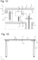
- Figure 1C shows a schematic diagram of the components in the height adjustable office furniture 1.
- the table top 2 with top surface 21 and bottom surface 22 is indirectly connected to a drive unit 6 via the support frame 4.
- a first resilient element 25 is provided in the connection between the table top 2 and the support frame 4.
- the first resilient element 25 is automatically also provided in the connection between the table top 2 and the drive unit 6.
- the first resilient element 25 is limited by a spacer 27 that ensures a minimum distance between the table top 2 and support frame 4 is always provided.
- the first resilient element 25 and spacer 27 define a suspension travel ⁇ z of the table top 2 extending along the vertical direction Z.
- the drive unit 6 includes a motor 61 and a spindle drive 64. After being connected to a power supply, the motor 61 drives rotation of a spindle drive 64 that extends through the leg unit 3 and actuates a mechanical lift system within the leg unit 3.
- the drive unit 6 is connected to the frame 4 using a second resilient element 65, limited in its movement by a guard 66.
- Figure 1D shows a front view of the height-adjustable office furniture 1 according to the invention.
- the table top 2 is resiliently mounted to the support frame 4. This means that the table top 2 and support frame 4 are not in direct contact with each other over their full length, but only at a limited number of positions.
- the connection between the table top 2 and support frame 4 is provided by a plurality of corner connections 23 and center connections 24.
- Figure 1E shows a cross-sectional detail of a corner connection 23.
- the support frame 4 extends substantially parallel to the table top 2.
- the bottom surface 22 of the table top 2 is connected to the frame using a pair of screws 42.
- the screws extend through part of the support frame 4 and into the table top 2.
- first resilient elements 25 are provided around the screws 42.
- the first resilient elements 25 are made of rubber and provide isolation of the table top 2 from the support frame 4.
- the first resilient element 25 is ring shaped and has a circumferentially extending receptacle 26 for receiving the support frame 4. It will be understood that dependent on the shape of the support frame 4 a varying number of screws 42 may be used.
- Figure 1F shows a cross-sectional detail of a center connection 24.
- the center screw 24 is provided with a spacer 27 that is arranged between the table top 2 and the support frame 4.
- the spacer 27 is shaped as a ring and is made of a plastic material.
- a number of center screws 24 are provided between the table top 2 and the support frame 4 to ensure a stable support. It will be understood that dependent on the size of the desk, just a few or more screws 44 and spacers 27 may be provided. Rubber rings 28 are provided between the table top 2 and the support frame 4.
- the first resilient elements 25 define the suspension travel ⁇ z extending along the vertical direction Z.
- the reduction in vibrations of the table top 4 increase the accuracy of the sensor 9 in the anti-collision system 8. In comparison to systems without a resilient element, the accuracy of the sensor can be increased by approximately 20%.
- the corner connections 23 and central connections 24 should be considered in all respects only as illustrative and not restrictive. In embodiments, only one type of connection may be provided with both a resilient element and a spacer integrated in the same connection.
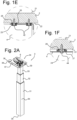
- FIG. 2A shows a perspective view of a leg unit 3 of the office furniture 1.
- the leg unit 3 includes a telescopic type leg having leg segments 31, 32, and 33.
- the spindle drive 64 is extending through the leg unit 3, which provides the mechanical lift system within the leg unit 3.
- the leg unit has a top end 34 and a bottom end 35.
- the top end 34 is provided with a mounting plate 36.
- the mounting plate has two mounting flanges 37 with openings 38. Bolts may be provided through these openings to connect the leg unit 3 to the support frame 4. It will be understood though that in other embodiments, the leg units 3 may also be directly connected to the table top 2.
- the mounting plate 36 is further provided with a deepened portion 39 that provides space for a drive unit 6.
- FIG. 2B shows a detailed view of the drive unit 6 and mounting plate 36 of the leg unit 3.
- the drive unit 6 includes a motor 61 a spindle plate 62 and a spindle drive 64.
- the spindle plate 62 connects to the spindle drive 64 and carries the other elements of the drive unit 6.
- the motor 61 drives rotation of a spindle drive 64 that extends through the leg segments 31, 32, 33 and actuates the mechanical lift system within the leg unit 3.
- the spindle plate 62 is connected to the frame using a plurality of mounting studs 63.
- FIG. 2C shows a simplified detail of the connection of the drive unit 6 to the mounting plate 36 through the mounting studs 63.
- the spindle plate 62 is spaced at a distance of the mounting plate 36 using a second resilient element 65 that supports the spindle plate 62.
- the second resilient element 65 is a rubber ring with a circumferential groove 67 along its outer circumferential surface.
- the spindle plate 62 is supported within the circumferential groove 67.
- the second resilient element 65 is surrounded by a guard 66 which ensures that the second resilient element 65 is not fastened too tight during assembly in a way that the resilient properties of the second resilient element 65 would not have any effect.
- the guard 66 is made of steel but also could be made of another metal, metal alloy, or even of a plastic material, as long as the guard 66 has a higher hardness than the rubber of the second resilient element 65.
Abstract
Description
- The invention relates to height-adjustable office furniture and a frame for height adjustable office furniture.
- In offices it is frequently desired to provide a working or sitting surface with an adjustable height. To that end, electronically adjustable office furniture is provided, such as sit-stand desks, drawing tables, or office chairs.
- For example, patent document
US 2018/0235360 A1 shows a height adjustable workstation. The workstation has a top workspace area and a movable base consisting of two or four legs, wherein each movable leg includes a linear actuator mechanism and a power box. The power box controls the movement of the linear actuator mechanism which further controls the movement of the legs such that the work station can be raised and lowered on command. - A problem experienced with the known adjustable office furniture is their noise production and the occurrence of vibrations of the top workspace area during height adjustment. It would be desirable to provide electronically height-adjustable office furniture, which improves on existing furniture, reduces noise production and/or reduces vibrations.
- Therefore, according to a first aspect of the invention, there is provided height-adjustable office furniture comprising a table top having a top surface and a bottom surface opposite to the top surface; at least one height adjustable leg unit connected to the table top, wherein the at least one leg unit is provided with a drive unit to drive adjustment of the height of the leg, wherein a resilient element is provided in the connection between the drive unit and the table top, the resilient element defining a suspension travel of the table top extending along a vertical direction Z; the office furniture further comprising a drive control system configured to control and power the drive unit; and an anti-collision system connected to the drive control system and configured to detect when movement of the table top along the vertical direction Z is blocked.
- Here a blocked movement along the vertical direction Z includes both a full blockage wherein any movement of the table top is prevented as well as a partial block wherein movement of the table top is only slowed down due to an increased resistance experienced by the table top.
- Advantageously, the suspension travel reduces or prevents entirely that vibrations generated by the drive unit are passed on to the table top. Resonation of the table top is thereby significantly reduced, which reduces the noise production when adjusting the height of the office furniture. Consequently, the height of the table top may be adjusted at relatively high speeds while only generating moderate noise.
- The reduction in vibrations of the table top is further advantageous to the accuracy of the anti-collision system. The reduced vibrations enable the selection of a lower threshold value for the sensor to measure the acceleration and/or deceleration of the table top. Therefore a deceleration of the table top can be measured at an earlier stage, reducing the likelihood that something gets damaged when the table top collides with another object. The anti-collision system thus prevents or reduces the risk that the office furniture or other objects arranged in the vicinity of the office furniture get damaged when vertical movement of the table top is blocked.
- In an embodiment, the height-adjustable office furniture further comprises a support frame connected to the bottom surface of the table top, wherein the at least one height adjustable leg unit is connected to the table top through the support frame. The support frame supports the table top. Preferably, the table top is resiliently mounted to the frame to prevent vibration of the table top along with vibrations in the frame. Alternatively, the leg units may be directly connected to the table top. The support frame may include a hollow body, wherein a drive control system and/or components of the anti-collision system may be arranged. The support frame may further serve to house cables, such as for instance power cables that power the drive unit or drive units. In an embodiment, the resilient element is provided between the table top and the support frame.
- In an embodiment, a plurality of spacers is placed between the table top and the support frame. The spacers are preferably made of a plastic material or of metal and prevent resonation of the support frame and table top together. The plurality of spacers may be provided as separate elements between the table top and support frame, yet alternatively may also be integrated with the screws used for connecting the table top to the support frame. The guard function of the spacer is then directly provided by the screw. Advantageous to the integration of the spacers with the screws is that the office furniture is easier to assemble.
- In an embodiment, the resilient element is a first resilient element and a second resilient element is provided between the drive unit and the support frame.
- In an embodiment, the height-adjustable office furniture comprises a guard for receiving the second resilient element with the drive unit connected thereto, the guard preventing compression of the second resilient element during assembly of the office furniture. The guard prevents that the resilient element can get compressed during assembly of the office furniture. The guard thereby ensures that the resilient element can fulfill its function to reduce vibrations being passed on from the drive unit to the support frame.
- In an embodiment, the guard is made of a material that is harder than the material of the second resilient element. The resilient element is typically made of rubber. The guard can for instance be made of a metal, metal alloy or a plastic material. The increased hardness of the material of the guard ensures a proper function of the guard, wherein the guard does not compress when the resilient element compresses.
- In an embodiment, the drive unit comprises a spindle plate and the second resilient element supports the spindle plate. The second resilient element is supported by the table top or the support frame. All components of the drive unit are connected and/or supported by the spindle plate. As such, vibrations generated by the drive unit when adjusting the height of the office furniture are not passed on to the remainder of the office furniture, reducing vibrations of the table top and/or a support frame.
- In an embodiment, the resilient element is ring shaped with a circumferential groove along its outer circumferential surface to support the spindle plate of the drive unit.
- In an embodiment, the resilient element and/or the resilient pads are made of rubber. Rubber is ideally suited to provide sound insulation.
- In an embodiment, the anti-collision system comprises a sensor connected to the drive control system, wherein the sensor can measure vertical acceleration. The sensor can measure vertical acceleration and identify when the table top gets jammed. Alternatively, a position sensor could be used.
- In an embodiment, the sensor is provided at the table top, preferably at the bottom surface of the table top. Here the sensor can be placed out of sight. In embodiments, the support frame may have a partially hollow structure and the sensor and/or the drive control system can be placed in the partially hollow structure.
- In an embodiment, the height-adjustable office furniture is configured to adjust the height with an average speed of at least 1 cm/s, preferably at least 3 cm/s, more preferably at least 4 cm/s. Such speeds make the office furniture convenient to use as most height adjustments can be carried out within one minute, preferably in less than half a minute. Typically, more noise is produced when a higher average speed is used, yet due to the travel suspension between the drive unit and the table top a relatively high average speed is possible for only a moderate noise production.
- In an embodiment, the noise produced by the height adjustment of the desk is less than 50 dB, preferably less than 45 dB, and more preferably less than 40 dB.
- In an embodiment, the table top is made of a light-weight material such as wood. Specifically light-weight materials such a wood have the tendency to resonate strongly when the office furniture is adjusted in height. As such, the invention is particularly suited for table tops made of such light-weight materials. Here a light-weight material is defined as any material having a density of less than 1000 kg/m3.
- According to a second aspect of the invention, and in accordance with the effects and advantages as described herein above, there is provided a height adjustable leg unit for the height-adjustable office furniture according to the invention. The height adjustable leg unit is provided with a drive unit that is configured to be only resiliently mounted to the other components of the office furniture.
- According to a further aspect of the invention, and in accordance with the effects and advantages as described herein above, there is provided a frame structure for the height-adjustable office furniture according to the invention. The frame structure comprises a support frame configured to support a table top; at least one height adjustable leg unit connected to the support frame, wherein each leg unit is provided with a drive unit to drive adjustment of the height of the leg, wherein a resilient element is provided in the connection between the drive unit and the support frame, the resilient element defining a suspension travel of the table top extending along a vertical direction Z; the frame structure further comprising a drive control system configured to control and power the at least one drive units; and configured to be connected to an anti-collision system. The frame structure is typically configured to receive a table top. In an embodiment, the frame structure is configured to receive a plurality op spacers and/or resilient pads to resiliently mount a table top to the frame structure.
- Embodiments will now be described, by way of example only, with reference to the accompanying schematic drawings in which corresponding reference symbols indicate corresponding parts. In the drawings, like numerals designate like elements. Multiple instances of an element may each include separate letters appended to the reference number. For example, two instances of a particular element "20" may be labeled as "20a" and "20b". The reference number may be used without an appended letter (e.g. "20") to generally refer to an unspecified instance or to all instances of that element, while the reference number will include an appended letter (e.g. "20a") to refer to a specific instance of the element.
- Figure 1A shows a perspective view of a first embodiment of height-adjustable office furniture.
- Figure 1B shows a bottom view of the height-adjustable office furniture in
Fig. 1A . - Figure 1C shows a schematic diagram of the components in the height adjustable office furniture in
Figs. 1A and 1B . - Figure 1D shows a cross-sectional view of the height-adjustable office furniture in
Figs. 1A and 1B . - Figures 1E and 1F show a cross-sectional view of two details of the height-adjustable office furniture as indicated in
Figure 1D . - Figure 2A shows a perspective view of a leg unit of the height-adjustable office furniture in
Fig. 1A . - Figure 2B shows a detail of the leg unit as indicated in
Fig. 2A . - Figure 2C shows a cross-sectional side view of a mounting stud.
- The figures are meant for illustrative purposes only, and do not serve as restriction of the scope or the protection as laid down by the claims.
- The following is a description of certain embodiments of the invention, given by way of example only and with reference to the figures.
-
Figure 1A shows a perspective view of a first embodiment of a piece of height-adjustable office furniture 1. The piece of height-adjustable office furniture 1 is a desk, which has atable top 2 with atop surface 21 and abottom surface 22, two heightadjustable leg units 3, asupport frame 4 and acontrol panel 71 for adjusting the height of the desk. Thetop surface 21 of thetable top 2 is arranged opposite to thebottom surface 22 and thesupport frame 4 is engaged to thetable top 2 at thebottom surface 22. The heightadjustable leg units 3 are connected to each other and thetable top 2 through thesupport frame 4. -
Figure 1B schematically shows a bottom view of the heightadjustable office furniture 1 inFig. 1A . Theoffice furniture 1 comprises a centraldrive control system 7 and ananti-collision system 8, which are both indicated only schematically. Thedrive control system 7 is configured to control a height adjustment of both theleg units 3 theoffice furniture 1. Thedrive control system 7 can be connected to a power source (not shown). Theanti-collision system 8 includes a sensor 9 (schematically indicated) that can measure vertical acceleration, and which is operatively connected to thedrive control system 7 and configured to detect when movement of thetable top 2 along the vertical direction Z is slowed down or blocked. The sensor 9 is preferably directly mounted onto the table top where the vibrations are optimally reduced, but it will be understood that alternatively the sensor 9 might also be mounted to thesupport frame 4. Thedrive control system 7 is configured to stop height adjustment of theoffice furniture 1 when the vertical movement to adjust the height is blocked. - The
drive control system 7 is operatively connected to thecontrol panel 71 which can be operated by a user to adjust the desk in height. Thedrive control system 7 can adjust the height of the desk with an average speed of 4 cm/s. During such height adjustment a noise having a strength of maximum 45 dB is created. This combination of relatively high adjustment speed with low volume noise can be created due to a suspension travel of the table top in its connection to the heightadjustable leg units 3. -
Figure 1C shows a schematic diagram of the components in the heightadjustable office furniture 1. Thetable top 2 withtop surface 21 andbottom surface 22 is indirectly connected to adrive unit 6 via thesupport frame 4. A firstresilient element 25 is provided in the connection between thetable top 2 and thesupport frame 4. Hence the firstresilient element 25 is automatically also provided in the connection between thetable top 2 and thedrive unit 6. The firstresilient element 25 is limited by aspacer 27 that ensures a minimum distance between thetable top 2 andsupport frame 4 is always provided. The firstresilient element 25 andspacer 27 define a suspension travel Δz of thetable top 2 extending along the vertical direction Z. - The
drive unit 6 includes amotor 61 and aspindle drive 64. After being connected to a power supply, themotor 61 drives rotation of aspindle drive 64 that extends through theleg unit 3 and actuates a mechanical lift system within theleg unit 3. Thedrive unit 6 is connected to theframe 4 using a secondresilient element 65, limited in its movement by aguard 66. -
Figure 1D shows a front view of the height-adjustable office furniture 1 according to the invention. Thetable top 2 is resiliently mounted to thesupport frame 4. This means that thetable top 2 andsupport frame 4 are not in direct contact with each other over their full length, but only at a limited number of positions. The connection between thetable top 2 andsupport frame 4 is provided by a plurality ofcorner connections 23 andcenter connections 24. -
Figure 1E shows a cross-sectional detail of acorner connection 23. Near the edges of thetable top 2, thesupport frame 4 extends substantially parallel to thetable top 2. Thebottom surface 22 of thetable top 2 is connected to the frame using a pair ofscrews 42. The screws extend through part of thesupport frame 4 and into thetable top 2. Around thescrews 42, firstresilient elements 25 are provided. The firstresilient elements 25 are made of rubber and provide isolation of the table top 2 from thesupport frame 4. The firstresilient element 25 is ring shaped and has acircumferentially extending receptacle 26 for receiving thesupport frame 4. It will be understood that dependent on the shape of the support frame 4 a varying number ofscrews 42 may be used. -
Figure 1F shows a cross-sectional detail of acenter connection 24. Thecenter screw 24 is provided with aspacer 27 that is arranged between thetable top 2 and thesupport frame 4. Thespacer 27 is shaped as a ring and is made of a plastic material. A number of center screws 24 are provided between thetable top 2 and thesupport frame 4 to ensure a stable support. It will be understood that dependent on the size of the desk, just a few ormore screws 44 andspacers 27 may be provided. Rubber rings 28 are provided between thetable top 2 and thesupport frame 4. - The first
resilient elements 25 define the suspension travel Δz extending along the vertical direction Z. The firstresilient elements 25, aided by the rubber rings 28, thereby prevent vibrations in thesupport frame 4 from being passed on to thetable top 2. This leads to a reduction of the noise that is generated when theoffice furniture 1 is adjusted in height. In addition, the reduction in vibrations of thetable top 4 increase the accuracy of the sensor 9 in theanti-collision system 8. In comparison to systems without a resilient element, the accuracy of the sensor can be increased by approximately 20%. Thecorner connections 23 andcentral connections 24 should be considered in all respects only as illustrative and not restrictive. In embodiments, only one type of connection may be provided with both a resilient element and a spacer integrated in the same connection. -
Figure 2A shows a perspective view of aleg unit 3 of theoffice furniture 1. Theleg unit 3 includes a telescopic type leg havingleg segments spindle drive 64 is extending through theleg unit 3, which provides the mechanical lift system within theleg unit 3. The leg unit has atop end 34 and abottom end 35. Thetop end 34 is provided with a mountingplate 36. The mounting plate has two mountingflanges 37 withopenings 38. Bolts may be provided through these openings to connect theleg unit 3 to thesupport frame 4. It will be understood though that in other embodiments, theleg units 3 may also be directly connected to thetable top 2. The mountingplate 36 is further provided with a deepenedportion 39 that provides space for adrive unit 6. -
Figure 2B shows a detailed view of thedrive unit 6 and mountingplate 36 of theleg unit 3. Thedrive unit 6 includes a motor 61 aspindle plate 62 and aspindle drive 64. Thespindle plate 62 connects to thespindle drive 64 and carries the other elements of thedrive unit 6. After being connected to a power supply, themotor 61 drives rotation of aspindle drive 64 that extends through theleg segments leg unit 3. Thespindle plate 62 is connected to the frame using a plurality of mountingstuds 63. -
Figure 2C shows a simplified detail of the connection of thedrive unit 6 to the mountingplate 36 through the mountingstuds 63. Thespindle plate 62 is spaced at a distance of the mountingplate 36 using a secondresilient element 65 that supports thespindle plate 62. The secondresilient element 65 is a rubber ring with acircumferential groove 67 along its outer circumferential surface. Thespindle plate 62 is supported within thecircumferential groove 67. - The second
resilient element 65 is surrounded by aguard 66 which ensures that the secondresilient element 65 is not fastened too tight during assembly in a way that the resilient properties of the secondresilient element 65 would not have any effect. Theguard 66 is made of steel but also could be made of another metal, metal alloy, or even of a plastic material, as long as theguard 66 has a higher hardness than the rubber of the secondresilient element 65. - The present invention may be embodied in other specific forms without departing from its spirit or essential characteristics. The described embodiments are to be considered in all respects only as illustrative and not restrictive. The scope of the invention is, therefore, indicated by the appended claims rather than by the foregoing description. It will be apparent to the person skilled in the art that alternative and equivalent embodiments of the invention can be conceived and reduced to practice. All changes which come within the meaning and range of equivalency of the claims are to be embraced within their scope.
Claims (15)
- Height-adjustable office furniture comprising:- a table top having a top surface and a bottom surface opposite to the top surface;- at least one height adjustable leg unit connected to the table top, wherein the at least one leg unit is provided with a drive unit to drive adjustment of the height of the leg, wherein a resilient element is provided in the connection between the drive unit and the table top, the resilient element defining a suspension travel of the table top extending along a vertical direction Z; the office furniture further comprising- a drive control system configured to control and power the drive unit; and- an anti-collision system connected to the drive control system and configured to detect when movement of the table top along the vertical direction Z is blocked.
- Height-adjustable office furniture according to claim 1 further comprising a support frame connected to the bottom surface of the table top, wherein the at least one height adjustable leg unit is connected to the table top through the support frame.
- Height-adjustable office furniture according to claim 2 wherein the resilient element is provided between the table top and a support frame.
- Height-adjustable office furniture according to claim 2 or 3, wherein a plurality of spacers is placed between the table top and the support frame, preferably wherein the spacers are made of a plastic material or metal.
- Height-adjustable office furniture according to claim 3 or 4 as long as dependent on claim 3, wherein the resilient element is a first resilient element and wherein a second resilient element is provided between the drive unit and the support frame.
- Height-adjustable office furniture according to claim 5 comprising a guard for receiving the second resilient element with the drive unit connected thereto, the guard preventing compression of the second resilient element during assembly of the office furniture, preferably wherein the guard is made of a material that is harder than the material of the second resilient element.
- Height-adjustable office furniture according to claims 5 or 6, wherein the drive unit comprises a spindle plate and wherein the second resilient element supports the spindle plate.
- Height-adjustable office furniture according to claim 7, wherein the second resilient element is ring shaped with a circumferential groove along its outer circumferential surface to support the spindle plate of the drive unit.
- Height-adjustable office furniture according to any of the preceding claims, wherein the first and/or second resilient elements are made of rubber.
- Height-adjustable office furniture according to any of the preceding claims, wherein the anti-collision system comprises a sensor connected to the drive control system, wherein the sensor can measure vertical acceleration and/or deceleration, preferably wherein the sensor is provided at the table top, more preferably at the bottom surface of the table top.
- Height-adjustable office furniture according to any of the preceding claims configured to adjust the height with an average speed of at least 2 cm/s, preferably at least 4 cm/s.
- Height-adjustable office furniture according to any of the preceding claims, wherein the noise produced by the height adjustment of the desk is less than 50 dB, preferably less than 45 dB, and more preferably less than 40 dB.
- Height-adjustable office furniture according to any of the preceding claim, wherein the table top is made of a light-weight material such as wood.
- A height adjustable leg unit for the height-adjustable office furniture according to any of claims 1-13.
- A frame structure for the height-adjustable office furniture according to any of claims 1-14, the frame structure comprising- a support frame configured to support a table top;- at least one height adjustable leg unit connected to the support frame, wherein the at least one leg unit is provided with a drive unit to drive adjustment of the height of the leg, wherein a resilient element is provided in the connection between the drive unit and the support frame, the resilient element defining a suspension travel of the table top extending along a vertical direction Z; the frame structure further comprising- a drive control system configured to control and power the drive unit; and configured to be connected to an anti-collision system.
Priority Applications (3)
| Application Number | Priority Date | Filing Date | Title |
|---|---|---|---|
| EP21204781.5A EP4173520A1 (en) | 2021-10-26 | 2021-10-26 | Height-adjustable office furniture |
| AU2022259735A AU2022259735A1 (en) | 2021-10-26 | 2022-10-25 | Height-adjustable office furniture |
| US17/972,619 US20230131791A1 (en) | 2021-10-26 | 2022-10-25 | Height-adjustable office furniture |
Applications Claiming Priority (1)
| Application Number | Priority Date | Filing Date | Title |
|---|---|---|---|
| EP21204781.5A EP4173520A1 (en) | 2021-10-26 | 2021-10-26 | Height-adjustable office furniture |
Publications (1)
| Publication Number | Publication Date |
|---|---|
| EP4173520A1 true EP4173520A1 (en) | 2023-05-03 |
Family
ID=78413679
Family Applications (1)
| Application Number | Title | Priority Date | Filing Date |
|---|---|---|---|
| EP21204781.5A Pending EP4173520A1 (en) | 2021-10-26 | 2021-10-26 | Height-adjustable office furniture |
Country Status (3)
| Country | Link |
|---|---|
| US (1) | US20230131791A1 (en) |
| EP (1) | EP4173520A1 (en) |
| AU (1) | AU2022259735A1 (en) |
Citations (6)
| Publication number | Priority date | Publication date | Assignee | Title |
|---|---|---|---|---|
| KR101597741B1 (en) * | 2015-08-06 | 2016-02-25 | (주)캠퍼스라인 | Desk height adjustment bracket is equipped with anti-vibration |
| DE102016212642B3 (en) * | 2016-07-12 | 2018-01-04 | Veyhl Gmbh | Bearing device for the drive shaft of a telescopic lifting column and furniture base |
| US20180235360A1 (en) | 2016-08-30 | 2018-08-23 | Xu Li | Adaptable workstation |
| CN108542108A (en) * | 2018-06-15 | 2018-09-18 | 常州市凯迪电器股份有限公司 | Electricity drives lifting type table pushing device and the table frame with the table pushing device and desk |
| US10094456B2 (en) * | 2014-05-13 | 2018-10-09 | Zhejiang Jiecang Linear Motion Technology Co., Ltd. | Actuator and applications of same |
| CN213820297U (en) * | 2020-11-13 | 2021-07-30 | 江门市品华家具有限公司 | Negotiation desk with magnetic force activity adjusting device |
Family Cites Families (28)
| Publication number | Priority date | Publication date | Assignee | Title |
|---|---|---|---|---|
| US2819134A (en) * | 1956-02-04 | 1958-01-07 | Klevholm Karl Eric | Hoisting and lowering devices for boards or plates |
| US4635565A (en) * | 1984-12-11 | 1987-01-13 | Interquad, Inc. | Variable height table |
| US6352037B1 (en) * | 2000-02-28 | 2002-03-05 | Suspa Incorporated | Position sensor holder and cover for motor drive unit |
| US6820908B1 (en) * | 2000-04-28 | 2004-11-23 | Freundenberg-Nok General Partnership | Isolation mount |
| SE0802030L (en) * | 2008-09-24 | 2009-11-17 | Swedestyle Ab | Device for mounting a table top on a rack with drive means |
| JP4703751B2 (en) * | 2009-09-09 | 2011-06-15 | 株式会社東芝 | Electronics |
| PL2583586T5 (en) * | 2011-10-18 | 2021-10-11 | Kesseböhmer Produktions GmbH & Co. KG | Device for detecting collisions and method |
| US9486070B2 (en) * | 2012-10-10 | 2016-11-08 | Stirworks Inc. | Height-adjustable support surface and system for encouraging human movement and promoting wellness |
| DE102013107053B4 (en) * | 2013-03-22 | 2015-04-09 | Logicdata Electronic & Software Entwicklungs Gmbh | Operating device for an electrically height-adjustable table, electrically height-adjustable table, drive system for an electrically height-adjustable table and method for height adjustment of a table top of a table |
| EP3031356A1 (en) * | 2014-12-12 | 2016-06-15 | KIH-utveckling AB | Height-adjustable table using eye detection |
| WO2018012526A1 (en) * | 2016-07-12 | 2018-01-18 | 株式会社岡村製作所 | Top panel elevating-type furniture |
| US11058216B2 (en) * | 2016-09-26 | 2021-07-13 | Kessebohmer Produktions Gmbh & Co. Kg | Control of a height adjustable table using fingerprints |
| US10436242B2 (en) * | 2016-12-20 | 2019-10-08 | Zhejiang Jiecang Linear Motion Technology Co., Ltd. | Telescopic transmission assembly and lifting column using same |
| US10470563B2 (en) * | 2017-05-24 | 2019-11-12 | Vitra Patente Ag | Height-adjustable piece of furniture and cable protector for such a piece of furniture |
| WO2019055078A1 (en) * | 2017-09-18 | 2019-03-21 | Fellowes, Inc. | Variable height platform system |
| AU2018236866A1 (en) * | 2017-10-02 | 2019-04-18 | SpaceCo Business Solutions, Inc. | System for reducing injury from pinch zones in adjustable height work surface assemblies |
| WO2019174686A2 (en) * | 2018-03-14 | 2019-09-19 | Linak A/S | Frame for a table |
| US20190328129A1 (en) * | 2018-04-30 | 2019-10-31 | QualGear LLC | Automatically adjustable desk and tabletop desk with presence detection, usage tracking and methods thereof |
| WO2019210917A1 (en) * | 2018-05-02 | 2019-11-07 | Linak A/S | Slider element for lifting columns |
| US10729233B2 (en) * | 2018-05-24 | 2020-08-04 | OMT-Veyhl USA Corporation | Length adjustable support and components of same |
| CN109700173A (en) * | 2018-05-31 | 2019-05-03 | 乐歌人体工学科技股份有限公司 | Same table control method |
| WO2020083432A1 (en) * | 2018-10-22 | 2020-04-30 | Oelschläger Metalltechnik GmbH | Furniture systems and method for carrying out a local fault diagnosis and optionally an expanded remote fault diagnosis for at least one electrically height-adjustable table and various systems and methods for automatically adjusting the height of the table top of an electrically height-adjustable table |
| US11304508B2 (en) * | 2019-01-08 | 2022-04-19 | OMT—VEYHL USA Corporation | Height adjustable table and components of same |
| CN110250739A (en) * | 2019-04-18 | 2019-09-20 | 美国乐歌有限公司 | It realizes the electric elevatable table bench control system and method for the rollback that is hampered |
| CN110778673B (en) * | 2019-09-12 | 2023-05-26 | 浙江捷昌线性驱动科技股份有限公司 | Self-locking device of linear actuator and linear actuator |
| DE102020209631A1 (en) * | 2020-07-30 | 2022-02-03 | Kesseböhmer Holding Kg | Lifting column and drive system for a lifting system of a piece of furniture |
| DE102020211550A1 (en) * | 2020-09-15 | 2022-03-17 | Kesseböhmer Holding Kg | Drive system for moving a height-adjustable tabletop, table with such a drive system and method for detecting a collision of a height-adjustable tabletop |
| TWM618980U (en) * | 2021-05-28 | 2021-11-01 | 第一傳動科技股份有限公司 | Lightweight electric table kickstand |
-
2021
- 2021-10-26 EP EP21204781.5A patent/EP4173520A1/en active Pending
-
2022
- 2022-10-25 US US17/972,619 patent/US20230131791A1/en active Pending
- 2022-10-25 AU AU2022259735A patent/AU2022259735A1/en active Pending
Patent Citations (6)
| Publication number | Priority date | Publication date | Assignee | Title |
|---|---|---|---|---|
| US10094456B2 (en) * | 2014-05-13 | 2018-10-09 | Zhejiang Jiecang Linear Motion Technology Co., Ltd. | Actuator and applications of same |
| KR101597741B1 (en) * | 2015-08-06 | 2016-02-25 | (주)캠퍼스라인 | Desk height adjustment bracket is equipped with anti-vibration |
| DE102016212642B3 (en) * | 2016-07-12 | 2018-01-04 | Veyhl Gmbh | Bearing device for the drive shaft of a telescopic lifting column and furniture base |
| US20180235360A1 (en) | 2016-08-30 | 2018-08-23 | Xu Li | Adaptable workstation |
| CN108542108A (en) * | 2018-06-15 | 2018-09-18 | 常州市凯迪电器股份有限公司 | Electricity drives lifting type table pushing device and the table frame with the table pushing device and desk |
| CN213820297U (en) * | 2020-11-13 | 2021-07-30 | 江门市品华家具有限公司 | Negotiation desk with magnetic force activity adjusting device |
Also Published As
| Publication number | Publication date |
|---|---|
| AU2022259735A1 (en) | 2023-05-11 |
| US20230131791A1 (en) | 2023-04-27 |
Similar Documents
| Publication | Publication Date | Title |
|---|---|---|
| US6213575B1 (en) | Kitchen countertop assembly with multiple, vertically adjustable integrated work spaces | |
| US4381714A (en) | Continuously adjustable computer console table | |
| US6708358B2 (en) | Articulating bed frame | |
| US5285733A (en) | Height-adjustable table with a linear or straight guide | |
| US20060230992A1 (en) | Workstation with adjustable height work surface | |
| US4781126A (en) | Adjustable desk-top assembly | |
| WO2013160647A1 (en) | Workspace booth | |
| EP3123899B1 (en) | Table with operating units adjustable in height | |
| EP4173520A1 (en) | Height-adjustable office furniture | |
| US6997116B2 (en) | Vertically height adjustable kitchen table assembly | |
| KR200491564Y1 (en) | A desk structure for music expert | |
| KR20160058559A (en) | Lift table | |
| CA2204560A1 (en) | Chair with vertically shiftable height adjustment | |
| US20220022644A1 (en) | Table Apparatus and Method | |
| CN213827051U (en) | Reinforcing mechanism convenient to disassemble and assemble spindle seat of vertical machining center | |
| KR101047587B1 (en) | Height Adjustable Counter | |
| EP3172989B1 (en) | Table with a height-adjustable top | |
| CN109965586A (en) | A kind of lifting bed system and structure | |
| JP6600880B2 (en) | Top and bottom lifting desk | |
| CN212244165U (en) | Elastic rubber needle machine | |
| KR102638046B1 (en) | Desk frame with height adjustment device | |
| EP3542007B1 (en) | Vertically adjustable sound absorbing screen | |
| JPH1033270A (en) | Top plate elevating and lowering device for desk | |
| CN213890346U (en) | Carpenter's table for interior decoration | |
| CN216534617U (en) | Office sofa with lifting function |
Legal Events
| Date | Code | Title | Description |
|---|---|---|---|
| PUAI | Public reference made under article 153(3) epc to a published international application that has entered the european phase |
Free format text: ORIGINAL CODE: 0009012 |
|
| STAA | Information on the status of an ep patent application or granted ep patent |
Free format text: STATUS: THE APPLICATION HAS BEEN PUBLISHED |
|
| AK | Designated contracting states |
Kind code of ref document: A1 Designated state(s): AL AT BE BG CH CY CZ DE DK EE ES FI FR GB GR HR HU IE IS IT LI LT LU LV MC MK MT NL NO PL PT RO RS SE SI SK SM TR |
|
| STAA | Information on the status of an ep patent application or granted ep patent |
Free format text: STATUS: REQUEST FOR EXAMINATION WAS MADE |
|
| 17P | Request for examination filed |
Effective date: 20231020 |
|
| RBV | Designated contracting states (corrected) |
Designated state(s): AL AT BE BG CH CY CZ DE DK EE ES FI FR GB GR HR HU IE IS IT LI LT LU LV MC MK MT NL NO PL PT RO RS SE SI SK SM TR |