EP3542007B1 - Vertically adjustable sound absorbing screen - Google Patents
Vertically adjustable sound absorbing screen Download PDFInfo
- Publication number
- EP3542007B1 EP3542007B1 EP17808014.9A EP17808014A EP3542007B1 EP 3542007 B1 EP3542007 B1 EP 3542007B1 EP 17808014 A EP17808014 A EP 17808014A EP 3542007 B1 EP3542007 B1 EP 3542007B1
- Authority
- EP
- European Patent Office
- Prior art keywords
- panel
- screen
- sound absorbing
- stand
- counterweight
- Prior art date
- Legal status (The legal status is an assumption and is not a legal conclusion. Google has not performed a legal analysis and makes no representation as to the accuracy of the status listed.)
- Active
Links
- 239000011358 absorbing material Substances 0.000 claims description 9
- 238000010521 absorption reaction Methods 0.000 claims description 3
- 238000000034 method Methods 0.000 claims description 3
- 239000006260 foam Substances 0.000 description 4
- -1 felt Polymers 0.000 description 3
- 239000000835 fiber Substances 0.000 description 3
- 239000004698 Polyethylene Substances 0.000 description 2
- 230000003247 decreasing effect Effects 0.000 description 2
- 229910052751 metal Inorganic materials 0.000 description 2
- 239000002184 metal Substances 0.000 description 2
- 238000005192 partition Methods 0.000 description 2
- 229920000573 polyethylene Polymers 0.000 description 2
- 229920000742 Cotton Polymers 0.000 description 1
- 229920000877 Melamine resin Polymers 0.000 description 1
- 239000004411 aluminium Substances 0.000 description 1
- 229910052782 aluminium Inorganic materials 0.000 description 1
- XAGFODPZIPBFFR-UHFFFAOYSA-N aluminium Chemical compound [Al] XAGFODPZIPBFFR-UHFFFAOYSA-N 0.000 description 1
- 230000005611 electricity Effects 0.000 description 1
- 239000011152 fibreglass Substances 0.000 description 1
- 239000011521 glass Substances 0.000 description 1
- 238000009413 insulation Methods 0.000 description 1
- 239000000463 material Substances 0.000 description 1
- JDSHMPZPIAZGSV-UHFFFAOYSA-N melamine Chemical compound NC1=NC(N)=NC(N)=N1 JDSHMPZPIAZGSV-UHFFFAOYSA-N 0.000 description 1
- 239000002861 polymer material Substances 0.000 description 1
- 239000002023 wood Substances 0.000 description 1
Images


Classifications
-
- E—FIXED CONSTRUCTIONS
- E04—BUILDING
- E04B—GENERAL BUILDING CONSTRUCTIONS; WALLS, e.g. PARTITIONS; ROOFS; FLOORS; CEILINGS; INSULATION OR OTHER PROTECTION OF BUILDINGS
- E04B2/00—Walls, e.g. partitions, for buildings; Wall construction with regard to insulation; Connections specially adapted to walls
- E04B2/74—Removable non-load-bearing partitions; Partitions with a free upper edge
- E04B2/7407—Removable non-load-bearing partitions; Partitions with a free upper edge assembled using frames with infill panels or coverings only; made-up of panels and a support structure incorporating posts
- E04B2/7409—Removable non-load-bearing partitions; Partitions with a free upper edge assembled using frames with infill panels or coverings only; made-up of panels and a support structure incorporating posts special measures for sound or thermal insulation, including fire protection
-
- E—FIXED CONSTRUCTIONS
- E04—BUILDING
- E04B—GENERAL BUILDING CONSTRUCTIONS; WALLS, e.g. PARTITIONS; ROOFS; FLOORS; CEILINGS; INSULATION OR OTHER PROTECTION OF BUILDINGS
- E04B1/00—Constructions in general; Structures which are not restricted either to walls, e.g. partitions, or floors or ceilings or roofs
- E04B1/38—Connections for building structures in general
- E04B1/61—Connections for building structures in general of slab-shaped building elements with each other
- E04B1/6108—Connections for building structures in general of slab-shaped building elements with each other the frontal surfaces of the slabs connected together
- E04B1/612—Connections for building structures in general of slab-shaped building elements with each other the frontal surfaces of the slabs connected together by means between frontal surfaces
- E04B1/6145—Connections for building structures in general of slab-shaped building elements with each other the frontal surfaces of the slabs connected together by means between frontal surfaces with recesses in both frontal surfaces co-operating with an additional connecting element
- E04B1/615—Connections for building structures in general of slab-shaped building elements with each other the frontal surfaces of the slabs connected together by means between frontal surfaces with recesses in both frontal surfaces co-operating with an additional connecting element the connection made by expansion
-
- E—FIXED CONSTRUCTIONS
- E04—BUILDING
- E04B—GENERAL BUILDING CONSTRUCTIONS; WALLS, e.g. PARTITIONS; ROOFS; FLOORS; CEILINGS; INSULATION OR OTHER PROTECTION OF BUILDINGS
- E04B2/00—Walls, e.g. partitions, for buildings; Wall construction with regard to insulation; Connections specially adapted to walls
- E04B2/74—Removable non-load-bearing partitions; Partitions with a free upper edge
- E04B2/7407—Removable non-load-bearing partitions; Partitions with a free upper edge assembled using frames with infill panels or coverings only; made-up of panels and a support structure incorporating posts
- E04B2/7416—Removable non-load-bearing partitions; Partitions with a free upper edge assembled using frames with infill panels or coverings only; made-up of panels and a support structure incorporating posts with free upper edge, e.g. for use as office space dividers
- E04B2/7433—Removable non-load-bearing partitions; Partitions with a free upper edge assembled using frames with infill panels or coverings only; made-up of panels and a support structure incorporating posts with free upper edge, e.g. for use as office space dividers with panels and support posts
-
- E—FIXED CONSTRUCTIONS
- E04—BUILDING
- E04B—GENERAL BUILDING CONSTRUCTIONS; WALLS, e.g. PARTITIONS; ROOFS; FLOORS; CEILINGS; INSULATION OR OTHER PROTECTION OF BUILDINGS
- E04B2/00—Walls, e.g. partitions, for buildings; Wall construction with regard to insulation; Connections specially adapted to walls
- E04B2/74—Removable non-load-bearing partitions; Partitions with a free upper edge
- E04B2/82—Removable non-load-bearing partitions; Partitions with a free upper edge characterised by the manner in which edges are connected to the building; Means therefor; Special details of easily-removable partitions as far as related to the connection with other parts of the building
- E04B2/827—Partitions constituted of sliding panels
-
- G—PHYSICS
- G10—MUSICAL INSTRUMENTS; ACOUSTICS
- G10K—SOUND-PRODUCING DEVICES; METHODS OR DEVICES FOR PROTECTING AGAINST, OR FOR DAMPING, NOISE OR OTHER ACOUSTIC WAVES IN GENERAL; ACOUSTICS NOT OTHERWISE PROVIDED FOR
- G10K11/00—Methods or devices for transmitting, conducting or directing sound in general; Methods or devices for protecting against, or for damping, noise or other acoustic waves in general
- G10K11/16—Methods or devices for protecting against, or for damping, noise or other acoustic waves in general
-
- G—PHYSICS
- G10—MUSICAL INSTRUMENTS; ACOUSTICS
- G10K—SOUND-PRODUCING DEVICES; METHODS OR DEVICES FOR PROTECTING AGAINST, OR FOR DAMPING, NOISE OR OTHER ACOUSTIC WAVES IN GENERAL; ACOUSTICS NOT OTHERWISE PROVIDED FOR
- G10K2210/00—Details of active noise control [ANC] covered by G10K11/178 but not provided for in any of its subgroups
- G10K2210/10—Applications
- G10K2210/118—Panels, e.g. active sound-absorption panels or noise barriers
Definitions
- This invention relates to a vertically adjustable sound-absorbing screen that can be used for example in office spaces.
- Known office partition systems such as the one disclosed in US 3 934 382 , has the disadvantage that they come in fixed sizes, resulting in non-flexible office partitions.
- US 5 918 422 discloses a vertically adjustable sound absorbing screen according to the preamble of claim 1.
- a vertically adjustable sound absorbing screen comprising a stand comprising two vertical supports, a vertical sound absorbing panel slidably arranged between the two vertical supports, said panel being vertically adjustable between a maximum upper position where the upper edge of the panel s above the stand, and a minimum lower position, said sound absorbing panel being balanced by at least one counterweight.
- the inventive screen has the advantage that it can be adjusted depending on the needs of the employees.
- the panel can be instantly adjusted to provide the desired amount of privacy or sound insulation, for example when an employee receives a telephone call and needs a quite environment.
- the panel can be raised.
- the panel can be lowered to provide the desired amount of contact or view.
- the inventive screen can also be used in restaurants, recording- or radio studios, etc.
- the height of the screen can also be adjusted depending on how tall a user is.
- Today, office desks with variable height is also used more and more. Some desks are possible to adjust between sitting and a standing working positions.
- the vertically adjustable screen makes it possible adapt the height of the sound absorbing screen to the height of the office desk.
- the panel is balanced by the at least one counterweight such that the panel can be vertically adjusted by hand.
- Hand powered adjustment has the advantage that there is no need for a motor or electricity which makes the screen reliable and makes it possible to produce the screen at low cost. It also makes the screen reliable as it can be operated without electrical power. Furthermore, the workplace can be kept less cluttered as there will be need for fewer electric supply cords.
- the panel can be adjusted to any vertical position between the maximum upper position and the minimum lower position.
- the panel is maintained in the vertical position by the counterweight. This provides a particular low cost and simple arrangement.
- the panel is balanced by the at least one counterweight such that the panel can be vertically adjusted by hand, the panel can be adjusted to any vertical position between the maximum upper position and the minimum lower position and the panel is maintained in the vertical position by the counterweight.
- This can be achieved by an embodiment where the sound absorbing panel is attached to a wire, rope, band or chain that runs over a roller, said roller being located at the upper end of the stand. It is preferred that the wire, rope or chain is attached in the lower end of the panel. This makes it possible to raise the panel as high above the stand as possible.
- the counterweight there is one counterweight that travels along both vertical supports, preferably in grooves along the vertical supports, where said grooves face each other.
- the counterweight may have the form of a horizontal bar.
- the panel can, in certain embodiments, be lowered to the extent that it is completely invisible, if the stand is lower than the office desk.
- the minimum lower position is such that the upper edge of the panel is above the upper edge of the stand.
- the screen is self-supporting. This allows easy placement and movement of the screen. This is achieved by the stand having a stand base.
- the stand base allows placement of the screen on the floor in a self-supporting manner.
- the sound absorbing panel preferably comprises a sound absorbing material.
- the sound absorbing material preferably has a sound absorption coefficient of at least 0.4, at 500 Hz.
- a method for adjusting the acoustic properties of a work space comprising vertically adjusting a screen as described above, to the desired height.
- the adjustment is preferably carried out by hand.
- the screen 1 is intended to be placed on the floor 2 of a work space, for example an office. It can for example be used between two adjacent work desks 3a, 3b.
- the screen 1 comprises a stand 4 that comprises at least two vertical supports 5a, 5b.
- the stand 4 is free standing, with the aid of stand base 6.
- the screen 1 does not have to be fixed to the floor or to a wall. If the screen 1 does not have support 6, two or more screens may be connected to provide support, for example by connecting the stands 4 at an angle (as seen from above). Alternatively the screen 1 may be fixed to the floor by bolts or the like.
- the height of the stand 4 can be such that it is slightly lower than average office desks. This makes it possible to conceal it to a great extent, if desired.
- the two vertical supports 5a, 5b are attached at a fixed distance. This may be achieved by at least one horizontal bar 8 that connects the two vertical supports 5a, 5b.
- the stand 4 may comprise a stiff board 9 or a glass pane 9 which is parallel to the panel 7. This provides additional stiffness and weight to the stand 4.
- the screen 1 comprises a sound absorbing panel 7 that will be described in more detail below.
- the panel 7 is vertically adjustable between a maximum upper position and a minimum lower position.
- Preferably the panel 7 travels vertically in grooves in the vertical supports, said grooves facing each other.
- the panel is balanced by counterweight 11, which may be a horizontal bar that extends between the vertical supports 5a, 5b.
- the counterweight 11 may be connected to the panel 7 by a wires that travels over rollers 12 at the top of vertical supports 5a, 5b as described below.
- the counterweight 11 makes it possible to easily adjust the height of the panel 7 by hand and also keeps the panel 7 immobile in the vertical position.
- the weight of the counterweight should be equal or almost equal to the weight of the panel 7.
- the counterweight does not completely balance the weight of the panel 7.
- the panel 7 may then be held in its vertical position by a number of vertically distributed detent positions.
- the detent positions can for example be spaced with 5 cm intervals.
- a suitable minimum lower position for the upper edge 15 of the panel 7 can be from 80 cm to 120 cm above the floor.
- a suitable maximum upper positon for the upper edge 15 can be from 160 cm to 200 cm above the floor.
- the upper edge 15 of the panel 7 is 100 cm above the floor in the lower position and about 180 cm above the floor in the upper position.
- the panel 7 can preferably be adjusted so that the upper edge 15 of the panel 7 is immobile anywhere between the minimum lower position and the maximum upper position. Thus the panel 7 can be left in such an arbitrary vertical position without moving vertically, and without the use of any additional brake or lock.
- the upper edge 15 of the panel 7 is above the upper edge 16 of the stand 4 and thus preferably above vertical supports 5a, 5b.
- the major part, for example at least 60% more preferably 80%, of the fixed height of the panel 7 may be above the upper edge 16 of vertical the stand in this position.
- the panel 7 comprises a sound absorbing material.
- the sounds absorbing material is preferably such that it absorbs sound and has a low weight and a low cost.
- the sound absorbing material may comprise for example a foam or fibers.
- One suitable type of fiber is fiberglass.
- the fibers or the foam may be made of a polymer material.
- the material may be for example cotton, felt, polyethylene fibres, polyethylene foam, or melamine foam.
- the sound absorption coefficient of the sound absorbing material at 500 Hz is preferably at least 0.4, more preferably at least 0.5, more preferably at least 0.6, more preferably at least 0.7, more preferably at least 0.8, more preferably at least 0.9, and most preferably at least 0.95.
- the thickness of the sound absorbing material in panel 7 is chosen such that it is thick enough to absorb sound to a sufficient extent, but thin enough so that screen 1 does not take up too much space and is not too heavy.
- the thickness of sound absorbing material in the panel 7 may be, for example, from 10-80 mm, more preferably 20-70 mm, even more preferably 25-60 mm.
- the panel 7 may comprise a frame 14 made in for example wood ( Fig. 5 ).
- FIG. 5 and 6 A possible mechanism for vertically adjusting the panel 7 can be seen in Figs. 5 and 6 where the screen 1 is seen from the other side compared to Figs. 3a and 4a .
- the panel 7 is connected to one end of a wire 10 that has a counterweight 11 attached to the other end.
- the counterweight may hang in wire 10.
- the wire 10 runs over a roller 12 located at the top of the vertical support 5a or 5b, which is hollow (5b is shown in the figure).
- the panel 7 may be attached to sliders 13 that travels in grooves in the vertical supports 5a and 5b.
- the counterweight 11 can travel vertically inside a space in the vertical support 5b, for example in a groove inside vertical support 5a or 5b.
- the counterweight is arranged as in Fig. 2a .
- wire 10 a rope, band or a chain may be used.
- the wire 10 may be metal wire.
- the weight of the counterweight 11 is preferably selected such that it (or they) balances the weight of the sound absorbing panel 7 such that the vertical position of the panel 7 can easily be changed by hand, and such that when the user lets go of the panel 7, the panel 7 remains in the vertical position where it is left by the user, as described above.
- the friction in the system comprising the wire 10 and the roller 12, the counterweight 11 and the slider 13 should be selected accordingly, but the skilled person knowns how to do that. A certain minimum friction may be required, in particular if a metal chain is used instead of a rope.
- the wire 11 may be arranged as a loop that travels over roller 12 and under a second roller at the bottom of the vertical supports 5a, 5b.
- the weight of the counterweight or -weights can be larger than the weight of the panel 7.
- the screen may have any suitable dimensions.
- a suitable length of the screen 1 may be from 1 m to 2 m.
- the width of the screen 1 can be from about 4 cm to about 15 cm.
- the height of the stand 4 may be from 80 cm to 120 cm, more preferably from 90 cm to 110 cm even more preferably from 95 cm to 105 cm.
- the fixed height of the panel 7 can have the same height as the stand 4 or can be higher or lower than the stand 4.
- the fixed height of the panel 7 may be from about 80 to 120 cm.
- the wire 10 is attached to the lower part of the panel 7. This makes it possible to raise the panel 7 to the maximum possible extent from the frame 4.
- the distance from the lower edge of the panel 7 to where the wire 10 is attached to the panel is less than 5% of the fixed height of the panel 7.
- the roller 12 is located as high as possible. This makes it possible to raise the panel 7 to the maximum possible extent in relation to the frame 4.
- the distance from the upper edge 16 of the stand 4 to the attachment site for the roller 12 at the vertical support 5a, 5b is less than 5% of the height of the vertical support 5a, 5b.
- the roller 12 may be located above the point where the wire 10 is attached to the panel 7, when the panel 7 is in the maximum upper position.
- the upper edge 15 of the panel 7 is above the upper edge 16 of the vertical stand 4 even when the panel 7 is in the minimum lower position ( Figs 2b and 4c ).
- This has the advantage that, when the frame 4 has the approximate height of an office desk, the panel will form a low divider between the desks.
- Such a screen 1 is suitably has upper edge 15 from 5 cm to 20 cm above the upper edge 16 of the frame 4 in the minimum lower position is b
- the stand 4 and in particular the vertical supports 5a and 5b can suitably be built from aluminium profiles.
- Such profiles can be hollow to contain the counterweight 11 or provide vertical grooves for counterweight 11 and also provide a sliding arrangement for the panel 7, for example by providing a groove for a slider 13.
- a method for adjusting the acoustic properties of a work desk 3a, 3b comprising adjusting the panel 7 of a screen 1 located adjacent to the work desk 3a 3b upwards or downwards from its initial position to a desired position so that the desired acoustic properties is achieved.
- the panel 7 is raised when sound level at the work des 3a 3b is to be decreased.
Description
- This invention relates to a vertically adjustable sound-absorbing screen that can be used for example in office spaces.
- Office space becomes more and more expensive. Often two or more employees must often share office space such that more than one office desk is located in one room. Open office floor plans facilitate cooperation and social contacts between employees. While this stimulates cooperation and communication between employees, it may also cause stress and distractions. In particular the noise level when two or more employees share the same room may be disturbing. This results in decreased productivity. Also, different task carried out by the same employee may require different levels of privacy and quietness. Different employees prefers different amounts of privacy and noise levels. Known office partition systems, such as the one disclosed in
US 3 934 382 , has the disadvantage that they come in fixed sizes, resulting in non-flexible office partitions. -
US 5 918 422 discloses a vertically adjustable sound absorbing screen according to the preamble ofclaim 1. - In a first aspect there is provided a vertically adjustable sound absorbing screen comprising a stand comprising two vertical supports, a vertical sound absorbing panel slidably arranged between the two vertical supports, said panel being vertically adjustable between a maximum upper position where the upper edge of the panel s above the stand, and a minimum lower position, said sound absorbing panel being balanced by at least one counterweight.
- The inventive screen has the advantage that it can be adjusted depending on the needs of the employees. The panel can be instantly adjusted to provide the desired amount of privacy or sound insulation, for example when an employee receives a telephone call and needs a quite environment. When the employees need privacy the panel can be raised. When the employees need to communicate or maybe wants a better view, the panel can be lowered to provide the desired amount of contact or view. The inventive screen can also be used in restaurants, recording- or radio studios, etc.
- The height of the screen can also be adjusted depending on how tall a user is. Today, office desks with variable height is also used more and more. Some desks are possible to adjust between sitting and a standing working positions. The vertically adjustable screen makes it possible adapt the height of the sound absorbing screen to the height of the office desk.
- The panel is balanced by the at least one counterweight such that the panel can be vertically adjusted by hand. Hand powered adjustment has the advantage that there is no need for a motor or electricity which makes the screen reliable and makes it possible to produce the screen at low cost. It also makes the screen reliable as it can be operated without electrical power. Furthermore, the workplace can be kept less cluttered as there will be need for fewer electric supply cords.
- In a preferred embodiment the panel can be adjusted to any vertical position between the maximum upper position and the minimum lower position.
- In a preferred embodiment, the panel is maintained in the vertical position by the counterweight. This provides a particular low cost and simple arrangement.
- The panel is balanced by the at least one counterweight such that the panel can be vertically adjusted by hand, the panel can be adjusted to any vertical position between the maximum upper position and the minimum lower position and the panel is maintained in the vertical position by the counterweight. This can be achieved by an embodiment where the sound absorbing panel is attached to a wire, rope, band or chain that runs over a roller, said roller being located at the upper end of the stand. It is preferred that the wire, rope or chain is attached in the lower end of the panel. This makes it possible to raise the panel as high above the stand as possible.
- In one embodiment there is one counterweight that travels along both vertical supports, preferably in grooves along the vertical supports, where said grooves face each other. For example, the counterweight may have the form of a horizontal bar. An advantage is that the vertical support can be made slimmer, that a larger counterweight can be used, and that there is a smaller risk for jamming of debris in the groove. Furthermore it reduces the risk of jamming due to skewing.
- The panel can, in certain embodiments, be lowered to the extent that it is completely invisible, if the stand is lower than the office desk. In one embodiment the minimum lower position is such that the upper edge of the panel is above the upper edge of the stand. This has the advantage that, when the stand is lower than an office desk, the panel will provide a low divider between two office desks in the lower position. Such a divider retains some privacy and also prevents movement of papers etc. between the desks, and may also prevents items on the desks from falling to the floor.
- The screen is self-supporting. This allows easy placement and movement of the screen. This is achieved by the stand having a stand base. The stand base allows placement of the screen on the floor in a self-supporting manner.
- The sound absorbing panel preferably comprises a sound absorbing material. The sound absorbing material preferably has a sound absorption coefficient of at least 0.4, at 500 Hz.
- In a second aspect of the invention there is provided a method for adjusting the acoustic properties of a work space comprising vertically adjusting a screen as described above, to the desired height. The adjustment is preferably carried out by hand.
-
-
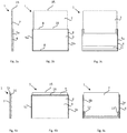
Fig. 1 shows a screen placed between two office desks, seen from the short ends of the office desks. -
Fig. 2a shows a screen with a sound absorbing panel in a maximum upper position. -
Fig. 2b shows a screen with a sound absorbing panel in a minimum lower position. -
Figs. 3a-c shows a screen with a sound absorbing panel in a maximum upper position. -
Figs. 4a-c shows a screen with a sound absorbing panel in a minimum lower position. -
Fig. 5-6 shows a screen with the panel in the maximum upper and minimum lower positions, respectively. - With reference to
Figs. 1 - 4 , thescreen 1 is intended to be placed on thefloor 2 of a work space, for example an office. It can for example be used between twoadjacent work desks - The
screen 1 comprises astand 4 that comprises at least twovertical supports stand 4 is free standing, with the aid ofstand base 6. Thus thescreen 1 does not have to be fixed to the floor or to a wall. If thescreen 1 does not havesupport 6, two or more screens may be connected to provide support, for example by connecting thestands 4 at an angle (as seen from above). Alternatively thescreen 1 may be fixed to the floor by bolts or the like. - The height of the
stand 4 can be such that it is slightly lower than average office desks. This makes it possible to conceal it to a great extent, if desired. - The two
vertical supports horizontal bar 8 that connects the twovertical supports stand 4 may comprise a stiff board 9 or a glass pane 9 which is parallel to thepanel 7. This provides additional stiffness and weight to thestand 4. - The
screen 1 comprises asound absorbing panel 7 that will be described in more detail below. Thepanel 7 is vertically adjustable between a maximum upper position and a minimum lower position. Preferably thepanel 7 travels vertically in grooves in the vertical supports, said grooves facing each other. - The panel is balanced by
counterweight 11, which may be a horizontal bar that extends between thevertical supports counterweight 11 may be connected to thepanel 7 by a wires that travels overrollers 12 at the top ofvertical supports counterweight 11 makes it possible to easily adjust the height of thepanel 7 by hand and also keeps thepanel 7 immobile in the vertical position. Thus the weight of the counterweight should be equal or almost equal to the weight of thepanel 7. Alternatively the counterweight does not completely balance the weight of thepanel 7. Thepanel 7 may then be held in its vertical position by a number of vertically distributed detent positions. The detent positions can for example be spaced with 5 cm intervals. - A suitable minimum lower position for the
upper edge 15 of thepanel 7 can be from 80 cm to 120 cm above the floor. A suitable maximum upper positon for theupper edge 15 can be from 160 cm to 200 cm above the floor. In a preferred embodiment theupper edge 15 of thepanel 7 is 100 cm above the floor in the lower position and about 180 cm above the floor in the upper position. Thepanel 7 can preferably be adjusted so that theupper edge 15 of thepanel 7 is immobile anywhere between the minimum lower position and the maximum upper position. Thus thepanel 7 can be left in such an arbitrary vertical position without moving vertically, and without the use of any additional brake or lock. - In the maximum upper position, the
upper edge 15 of thepanel 7 is above theupper edge 16 of thestand 4 and thus preferably abovevertical supports panel 7 may be above theupper edge 16 of vertical the stand in this position. - The
panel 7 comprises a sound absorbing material. The sounds absorbing material is preferably such that it absorbs sound and has a low weight and a low cost. The sound absorbing material may comprise for example a foam or fibers. One suitable type of fiber is fiberglass. The fibers or the foam may be made of a polymer material. The material may be for example cotton, felt, polyethylene fibres, polyethylene foam, or melamine foam. The sound absorption coefficient of the sound absorbing material at 500 Hz is preferably at least 0.4, more preferably at least 0.5, more preferably at least 0.6, more preferably at least 0.7, more preferably at least 0.8, more preferably at least 0.9, and most preferably at least 0.95. The thickness of the sound absorbing material inpanel 7 is chosen such that it is thick enough to absorb sound to a sufficient extent, but thin enough so thatscreen 1 does not take up too much space and is not too heavy. The thickness of sound absorbing material in thepanel 7 may be, for example, from 10-80 mm, more preferably 20-70 mm, even more preferably 25-60 mm. Thepanel 7 may comprise aframe 14 made in for example wood (Fig. 5 ). - A possible mechanism for vertically adjusting the
panel 7 can be seen inFigs. 5 and 6 where thescreen 1 is seen from the other side compared toFigs. 3a and 4a . In this embodiment, thepanel 7 is connected to one end of awire 10 that has acounterweight 11 attached to the other end. The counterweight may hang inwire 10. Thewire 10 runs over aroller 12 located at the top of thevertical support panel 7 may be attached tosliders 13 that travels in grooves in thevertical supports counterweight 11 can travel vertically inside a space in thevertical support 5b, for example in a groove insidevertical support vertical supports Fig. 2a . - Instead of
wire 10, a rope, band or a chain may be used. Thewire 10 may be metal wire. - The weight of the
counterweight 11 is preferably selected such that it (or they) balances the weight of thesound absorbing panel 7 such that the vertical position of thepanel 7 can easily be changed by hand, and such that when the user lets go of thepanel 7, thepanel 7 remains in the vertical position where it is left by the user, as described above. The friction in the system comprising thewire 10 and theroller 12, thecounterweight 11 and theslider 13 should be selected accordingly, but the skilled person knowns how to do that. A certain minimum friction may be required, in particular if a metal chain is used instead of a rope. - The
wire 11 may be arranged as a loop that travels overroller 12 and under a second roller at the bottom of thevertical supports - If a gear such as a system of pulleys is used, the weight of the counterweight or -weights can be larger than the weight of the
panel 7. - The screen may have any suitable dimensions. A suitable length of the
screen 1 may be from 1 m to 2 m. The width of thescreen 1 can be from about 4 cm to about 15 cm. The height of thestand 4 may be from 80 cm to 120 cm, more preferably from 90 cm to 110 cm even more preferably from 95 cm to 105 cm. The fixed height of thepanel 7 can have the same height as thestand 4 or can be higher or lower than thestand 4. The fixed height of thepanel 7 may be from about 80 to 120 cm. - Advantageously the
wire 10 is attached to the lower part of thepanel 7. This makes it possible to raise thepanel 7 to the maximum possible extent from theframe 4. In one embodiment the distance from the lower edge of thepanel 7 to where thewire 10 is attached to the panel is less than 5% of the fixed height of thepanel 7. - Advantageously the
roller 12 is located as high as possible. This makes it possible to raise thepanel 7 to the maximum possible extent in relation to theframe 4. In one embodiment the distance from theupper edge 16 of thestand 4 to the attachment site for theroller 12 at thevertical support vertical support - The
roller 12 may be located above the point where thewire 10 is attached to thepanel 7, when thepanel 7 is in the maximum upper position. - In one embodiment the
upper edge 15 of thepanel 7 is above theupper edge 16 of thevertical stand 4 even when thepanel 7 is in the minimum lower position (Figs 2b and4c ). This has the advantage that, when theframe 4 has the approximate height of an office desk, the panel will form a low divider between the desks. Such ascreen 1 is suitably hasupper edge 15 from 5 cm to 20 cm above theupper edge 16 of theframe 4 in the minimum lower position is b This also has the advantage that theframe 4 will not be seen as it can be placed so that is completely below the office desks. - The
stand 4 and in particular thevertical supports counterweight 11 or provide vertical grooves forcounterweight 11 and also provide a sliding arrangement for thepanel 7, for example by providing a groove for aslider 13. - With reference to
Fig 1 , there is also provided a method for adjusting the acoustic properties of awork desk panel 7 of ascreen 1 located adjacent to thework desk 3apanel 7 is raised when sound level at the work des3a 3b is to be decreased.
Claims (9)
- A vertically adjustable sound absorbing screen (1) comprising
a stand (4) comprising two vertical supports (5a, 5b)
a vertical sound absorbing panel (7) slidably arranged between the two vertical supports (5a, 5b),
where the screen is free standing with the use of a stand base (6) and
said panel (7) being vertically adjustable between an maximum upper position where the upper edge (15) of the panel (7) is above the stand (4), and a minimum lower position, characterized in that said sound absorbing panel (7) being balanced by at least one counterweight (11) such that the panel (7) can be vertically adjusted by hand. - The screen (1) according to claim 1 where the panel (7) can be adjusted to any vertical position between the maximum upper position and the minimum lower position.
- The screen (1) according to any one of claims 1 to 2 where the panel (7) is maintained in the vertical position by the counterweight (11).
- The screen (1) according to any one of claims 1 to 3 where the sound absorbing panel (7) is attached to a wire, rope, band or chain (10) that runs over a roller (12), said roller (12) being located at the upper end of the stand (4).
- The screen (1) according to any one of claims 1 to 4 where the wire, rope or chain (10) is attached in the lower end of the panel (7).
- The screen (1) according to any one of claims 1 to 5 where there is one counterweight (11) that travels along both vertical supports (5a, 5b).
- The screen (1) according to any one of claims 1 to 6 where the minimum lower position is such that the upper edge (15) of the panel is above the upper edge (16) of the stand (4).
- The screen (1) according to any one of claims 1 to 7 where the panel (7) comprises a sound absorbing material with a sound absorption coefficient of at least 0.4 at 500 Hz.
- A method for adjusting the acoustic properties of a work space comprising vertically adjusting a screen (1) according to any one of claims 1 to 8 to the desired height.
Applications Claiming Priority (2)
| Application Number | Priority Date | Filing Date | Title |
|---|---|---|---|
| SE1651518A SE541353C2 (en) | 2016-11-21 | 2016-11-21 | Vertically adjustable sound absorbing screen |
| PCT/EP2017/078990 WO2018091390A1 (en) | 2016-11-21 | 2017-11-13 | Vertically adjustable sound absorbing screen |
Publications (2)
| Publication Number | Publication Date |
|---|---|
| EP3542007A1 EP3542007A1 (en) | 2019-09-25 |
| EP3542007B1 true EP3542007B1 (en) | 2020-04-22 |
Family
ID=60543506
Family Applications (1)
| Application Number | Title | Priority Date | Filing Date |
|---|---|---|---|
| EP17808014.9A Active EP3542007B1 (en) | 2016-11-21 | 2017-11-13 | Vertically adjustable sound absorbing screen |
Country Status (3)
| Country | Link |
|---|---|
| EP (1) | EP3542007B1 (en) |
| SE (1) | SE541353C2 (en) |
| WO (1) | WO2018091390A1 (en) |
Family Cites Families (8)
| Publication number | Priority date | Publication date | Assignee | Title |
|---|---|---|---|---|
| US3934382A (en) | 1974-02-27 | 1976-01-27 | Gartung Clifford W | Modular sound-absorbing screens |
| US5918422A (en) * | 1997-05-14 | 1999-07-06 | Bucher, Jr.; Robert Joseph | Open office panel system |
| US6178702B1 (en) * | 1998-04-15 | 2001-01-30 | Steelcase Development Inc. | Flexible light seal for partition systems |
| EP1247918A1 (en) * | 2001-04-05 | 2002-10-09 | Yu-An Liu | Height-adjustable screen |
| US20080134601A1 (en) * | 2006-06-16 | 2008-06-12 | Apaxis Systems, Inc | Office workstation assembly |
| SE535163C2 (en) * | 2009-09-29 | 2012-05-02 | Svalson Ab | Balcony railing with integrated windscreen |
| ITMI20130341A1 (en) * | 2013-03-07 | 2014-09-08 | Gm Morando S R L | MODULAR SHIELDING SYSTEM |
| EP3102752A4 (en) * | 2014-01-22 | 2017-11-15 | AB Edsbyverken | A screen, a partition screen system and a method of making the screen |
-
2016
- 2016-11-21 SE SE1651518A patent/SE541353C2/en unknown
-
2017
- 2017-11-13 EP EP17808014.9A patent/EP3542007B1/en active Active
- 2017-11-13 WO PCT/EP2017/078990 patent/WO2018091390A1/en active Application Filing
Non-Patent Citations (1)
| Title |
|---|
| None * |
Also Published As
| Publication number | Publication date |
|---|---|
| EP3542007A1 (en) | 2019-09-25 |
| SE1651518A1 (en) | 2018-05-22 |
| WO2018091390A1 (en) | 2018-05-24 |
| SE541353C2 (en) | 2019-08-13 |
Similar Documents
| Publication | Publication Date | Title |
|---|---|---|
| CA2976565C (en) | Wall panel system | |
| US7398738B2 (en) | Workstation with adjustable height work surface | |
| FI68442B (en) | ANORDING FOR THE ABSORPTION OF AN ABSORPTION AVOID IN LOCAL | |
| US5375642A (en) | Venetian blinds | |
| US4263761A (en) | Portable acoustical panel system | |
| NL2017632B1 (en) | Office workplace system | |
| US8113606B2 (en) | Method and apparatus for optimizing storage space | |
| WO2013160647A1 (en) | Workspace booth | |
| US20120194042A1 (en) | Method and apparatus for optimizing storage space | |
| DK3241462T3 (en) | Furniture and / or room divider structure element | |
| EP3542007B1 (en) | Vertically adjustable sound absorbing screen | |
| US20220312956A1 (en) | Reconfigurable work station, work space, and work space system | |
| FIU990124U0 (en) | Support frame structure for stepless height and depth adjustment of kitchen cabinet top and bottom cabinets and worktop | |
| EP3175126B1 (en) | Modular wall system with slidable furniture | |
| EP2801678B1 (en) | Adaptive acoustic system and method for optimising the acoustics of a room | |
| DE102005044608A1 (en) | Upper kitchen unit or hanging file cabinet, comprises inner cubicle to be lowered by electrically operated blind winding system | |
| DE202013004449U1 (en) | Height-adjustable visible and soundproofing mat for workplaces | |
| ATE388651T1 (en) | CORNER CABINET WITH MOVEABLE BUILT-IN ELEMENTS | |
| US20150128508A1 (en) | Room-dividing element for an open-plan office | |
| KR200484286Y1 (en) | Partitions for compartmentalizing restaurants tables | |
| US4706728A (en) | Apparatus for mounting screens | |
| US20180320925A1 (en) | Apparatus for natural ventilation of a room | |
| CN217982174U (en) | Control console | |
| EP4173520A1 (en) | Height-adjustable office furniture | |
| CN203452581U (en) | Object storage cabinet with noise absorbing function |
Legal Events
| Date | Code | Title | Description |
|---|---|---|---|
| STAA | Information on the status of an ep patent application or granted ep patent |
Free format text: STATUS: UNKNOWN |
|
| STAA | Information on the status of an ep patent application or granted ep patent |
Free format text: STATUS: THE INTERNATIONAL PUBLICATION HAS BEEN MADE |
|
| PUAI | Public reference made under article 153(3) epc to a published international application that has entered the european phase |
Free format text: ORIGINAL CODE: 0009012 |
|
| STAA | Information on the status of an ep patent application or granted ep patent |
Free format text: STATUS: REQUEST FOR EXAMINATION WAS MADE |
|
| 17P | Request for examination filed |
Effective date: 20190410 |
|
| AK | Designated contracting states |
Kind code of ref document: A1 Designated state(s): AL AT BE BG CH CY CZ DE DK EE ES FI FR GB GR HR HU IE IS IT LI LT LU LV MC MK MT NL NO PL PT RO RS SE SI SK SM TR |
|
| AX | Request for extension of the european patent |
Extension state: BA ME |
|
| GRAP | Despatch of communication of intention to grant a patent |
Free format text: ORIGINAL CODE: EPIDOSNIGR1 |
|
| STAA | Information on the status of an ep patent application or granted ep patent |
Free format text: STATUS: GRANT OF PATENT IS INTENDED |
|
| DAV | Request for validation of the european patent (deleted) | ||
| DAX | Request for extension of the european patent (deleted) | ||
| INTG | Intention to grant announced |
Effective date: 20191115 |
|
| GRAS | Grant fee paid |
Free format text: ORIGINAL CODE: EPIDOSNIGR3 |
|
| GRAA | (expected) grant |
Free format text: ORIGINAL CODE: 0009210 |
|
| STAA | Information on the status of an ep patent application or granted ep patent |
Free format text: STATUS: THE PATENT HAS BEEN GRANTED |
|
| AK | Designated contracting states |
Kind code of ref document: B1 Designated state(s): AL AT BE BG CH CY CZ DE DK EE ES FI FR GB GR HR HU IE IS IT LI LT LU LV MC MK MT NL NO PL PT RO RS SE SI SK SM TR |
|
| REG | Reference to a national code |
Ref country code: CH Ref legal event code: EP |
|
| REG | Reference to a national code |
Ref country code: IE Ref legal event code: FG4D |
|
| REG | Reference to a national code |
Ref country code: DE Ref legal event code: R096 Ref document number: 602017015399 Country of ref document: DE |
|
| REG | Reference to a national code |
Ref country code: AT Ref legal event code: REF Ref document number: 1260236 Country of ref document: AT Kind code of ref document: T Effective date: 20200515 |
|
| REG | Reference to a national code |
Ref country code: CH Ref legal event code: NV Representative=s name: DENNEMEYER AG, CH |
|
| REG | Reference to a national code |
Ref country code: LT Ref legal event code: MG4D |
|
| REG | Reference to a national code |
Ref country code: NL Ref legal event code: MP Effective date: 20200422 |
|
| PG25 | Lapsed in a contracting state [announced via postgrant information from national office to epo] |
Ref country code: SE Free format text: LAPSE BECAUSE OF FAILURE TO SUBMIT A TRANSLATION OF THE DESCRIPTION OR TO PAY THE FEE WITHIN THE PRESCRIBED TIME-LIMIT Effective date: 20200422 Ref country code: NL Free format text: LAPSE BECAUSE OF FAILURE TO SUBMIT A TRANSLATION OF THE DESCRIPTION OR TO PAY THE FEE WITHIN THE PRESCRIBED TIME-LIMIT Effective date: 20200422 Ref country code: LT Free format text: LAPSE BECAUSE OF FAILURE TO SUBMIT A TRANSLATION OF THE DESCRIPTION OR TO PAY THE FEE WITHIN THE PRESCRIBED TIME-LIMIT Effective date: 20200422 Ref country code: GR Free format text: LAPSE BECAUSE OF FAILURE TO SUBMIT A TRANSLATION OF THE DESCRIPTION OR TO PAY THE FEE WITHIN THE PRESCRIBED TIME-LIMIT Effective date: 20200723 Ref country code: FI Free format text: LAPSE BECAUSE OF FAILURE TO SUBMIT A TRANSLATION OF THE DESCRIPTION OR TO PAY THE FEE WITHIN THE PRESCRIBED TIME-LIMIT Effective date: 20200422 Ref country code: PT Free format text: LAPSE BECAUSE OF FAILURE TO SUBMIT A TRANSLATION OF THE DESCRIPTION OR TO PAY THE FEE WITHIN THE PRESCRIBED TIME-LIMIT Effective date: 20200824 Ref country code: NO Free format text: LAPSE BECAUSE OF FAILURE TO SUBMIT A TRANSLATION OF THE DESCRIPTION OR TO PAY THE FEE WITHIN THE PRESCRIBED TIME-LIMIT Effective date: 20200722 Ref country code: IS Free format text: LAPSE BECAUSE OF FAILURE TO SUBMIT A TRANSLATION OF THE DESCRIPTION OR TO PAY THE FEE WITHIN THE PRESCRIBED TIME-LIMIT Effective date: 20200822 |
|
| REG | Reference to a national code |
Ref country code: AT Ref legal event code: MK05 Ref document number: 1260236 Country of ref document: AT Kind code of ref document: T Effective date: 20200422 |
|
| PG25 | Lapsed in a contracting state [announced via postgrant information from national office to epo] |
Ref country code: HR Free format text: LAPSE BECAUSE OF FAILURE TO SUBMIT A TRANSLATION OF THE DESCRIPTION OR TO PAY THE FEE WITHIN THE PRESCRIBED TIME-LIMIT Effective date: 20200422 Ref country code: LV Free format text: LAPSE BECAUSE OF FAILURE TO SUBMIT A TRANSLATION OF THE DESCRIPTION OR TO PAY THE FEE WITHIN THE PRESCRIBED TIME-LIMIT Effective date: 20200422 Ref country code: RS Free format text: LAPSE BECAUSE OF FAILURE TO SUBMIT A TRANSLATION OF THE DESCRIPTION OR TO PAY THE FEE WITHIN THE PRESCRIBED TIME-LIMIT Effective date: 20200422 Ref country code: BG Free format text: LAPSE BECAUSE OF FAILURE TO SUBMIT A TRANSLATION OF THE DESCRIPTION OR TO PAY THE FEE WITHIN THE PRESCRIBED TIME-LIMIT Effective date: 20200722 |
|
| PG25 | Lapsed in a contracting state [announced via postgrant information from national office to epo] |
Ref country code: AL Free format text: LAPSE BECAUSE OF FAILURE TO SUBMIT A TRANSLATION OF THE DESCRIPTION OR TO PAY THE FEE WITHIN THE PRESCRIBED TIME-LIMIT Effective date: 20200422 |
|
| REG | Reference to a national code |
Ref country code: DE Ref legal event code: R097 Ref document number: 602017015399 Country of ref document: DE |
|
| PG25 | Lapsed in a contracting state [announced via postgrant information from national office to epo] |
Ref country code: RO Free format text: LAPSE BECAUSE OF FAILURE TO SUBMIT A TRANSLATION OF THE DESCRIPTION OR TO PAY THE FEE WITHIN THE PRESCRIBED TIME-LIMIT Effective date: 20200422 Ref country code: CZ Free format text: LAPSE BECAUSE OF FAILURE TO SUBMIT A TRANSLATION OF THE DESCRIPTION OR TO PAY THE FEE WITHIN THE PRESCRIBED TIME-LIMIT Effective date: 20200422 Ref country code: ES Free format text: LAPSE BECAUSE OF FAILURE TO SUBMIT A TRANSLATION OF THE DESCRIPTION OR TO PAY THE FEE WITHIN THE PRESCRIBED TIME-LIMIT Effective date: 20200422 Ref country code: AT Free format text: LAPSE BECAUSE OF FAILURE TO SUBMIT A TRANSLATION OF THE DESCRIPTION OR TO PAY THE FEE WITHIN THE PRESCRIBED TIME-LIMIT Effective date: 20200422 Ref country code: DK Free format text: LAPSE BECAUSE OF FAILURE TO SUBMIT A TRANSLATION OF THE DESCRIPTION OR TO PAY THE FEE WITHIN THE PRESCRIBED TIME-LIMIT Effective date: 20200422 Ref country code: EE Free format text: LAPSE BECAUSE OF FAILURE TO SUBMIT A TRANSLATION OF THE DESCRIPTION OR TO PAY THE FEE WITHIN THE PRESCRIBED TIME-LIMIT Effective date: 20200422 Ref country code: SM Free format text: LAPSE BECAUSE OF FAILURE TO SUBMIT A TRANSLATION OF THE DESCRIPTION OR TO PAY THE FEE WITHIN THE PRESCRIBED TIME-LIMIT Effective date: 20200422 Ref country code: IT Free format text: LAPSE BECAUSE OF FAILURE TO SUBMIT A TRANSLATION OF THE DESCRIPTION OR TO PAY THE FEE WITHIN THE PRESCRIBED TIME-LIMIT Effective date: 20200422 |
|
| PG25 | Lapsed in a contracting state [announced via postgrant information from national office to epo] |
Ref country code: PL Free format text: LAPSE BECAUSE OF FAILURE TO SUBMIT A TRANSLATION OF THE DESCRIPTION OR TO PAY THE FEE WITHIN THE PRESCRIBED TIME-LIMIT Effective date: 20200422 Ref country code: SK Free format text: LAPSE BECAUSE OF FAILURE TO SUBMIT A TRANSLATION OF THE DESCRIPTION OR TO PAY THE FEE WITHIN THE PRESCRIBED TIME-LIMIT Effective date: 20200422 |
|
| PLBE | No opposition filed within time limit |
Free format text: ORIGINAL CODE: 0009261 |
|
| STAA | Information on the status of an ep patent application or granted ep patent |
Free format text: STATUS: NO OPPOSITION FILED WITHIN TIME LIMIT |
|
| 26N | No opposition filed |
Effective date: 20210125 |
|
| PG25 | Lapsed in a contracting state [announced via postgrant information from national office to epo] |
Ref country code: MC Free format text: LAPSE BECAUSE OF FAILURE TO SUBMIT A TRANSLATION OF THE DESCRIPTION OR TO PAY THE FEE WITHIN THE PRESCRIBED TIME-LIMIT Effective date: 20200422 |
|
| PG25 | Lapsed in a contracting state [announced via postgrant information from national office to epo] |
Ref country code: LU Free format text: LAPSE BECAUSE OF NON-PAYMENT OF DUE FEES Effective date: 20201113 |
|
| PG25 | Lapsed in a contracting state [announced via postgrant information from national office to epo] |
Ref country code: IE Free format text: LAPSE BECAUSE OF NON-PAYMENT OF DUE FEES Effective date: 20201113 |
|
| PG25 | Lapsed in a contracting state [announced via postgrant information from national office to epo] |
Ref country code: TR Free format text: LAPSE BECAUSE OF FAILURE TO SUBMIT A TRANSLATION OF THE DESCRIPTION OR TO PAY THE FEE WITHIN THE PRESCRIBED TIME-LIMIT Effective date: 20200422 Ref country code: MT Free format text: LAPSE BECAUSE OF FAILURE TO SUBMIT A TRANSLATION OF THE DESCRIPTION OR TO PAY THE FEE WITHIN THE PRESCRIBED TIME-LIMIT Effective date: 20200422 Ref country code: CY Free format text: LAPSE BECAUSE OF FAILURE TO SUBMIT A TRANSLATION OF THE DESCRIPTION OR TO PAY THE FEE WITHIN THE PRESCRIBED TIME-LIMIT Effective date: 20200422 |
|
| PG25 | Lapsed in a contracting state [announced via postgrant information from national office to epo] |
Ref country code: MK Free format text: LAPSE BECAUSE OF FAILURE TO SUBMIT A TRANSLATION OF THE DESCRIPTION OR TO PAY THE FEE WITHIN THE PRESCRIBED TIME-LIMIT Effective date: 20200422 |
|
| P01 | Opt-out of the competence of the unified patent court (upc) registered |
Effective date: 20230627 |
|
| PG25 | Lapsed in a contracting state [announced via postgrant information from national office to epo] |
Ref country code: SI Free format text: LAPSE BECAUSE OF FAILURE TO SUBMIT A TRANSLATION OF THE DESCRIPTION OR TO PAY THE FEE WITHIN THE PRESCRIBED TIME-LIMIT Effective date: 20200422 |
|
| PGFP | Annual fee paid to national office [announced via postgrant information from national office to epo] |
Ref country code: GB Payment date: 20231120 Year of fee payment: 7 |
|
| PGFP | Annual fee paid to national office [announced via postgrant information from national office to epo] |
Ref country code: FR Payment date: 20231115 Year of fee payment: 7 Ref country code: DE Payment date: 20231121 Year of fee payment: 7 Ref country code: CH Payment date: 20231201 Year of fee payment: 7 |
|
| PGFP | Annual fee paid to national office [announced via postgrant information from national office to epo] |
Ref country code: BE Payment date: 20231120 Year of fee payment: 7 |