EP3764508B1 - Stromversorgungsvorrichtung - Google Patents
Stromversorgungsvorrichtung Download PDFInfo
- Publication number
- EP3764508B1 EP3764508B1 EP20181970.3A EP20181970A EP3764508B1 EP 3764508 B1 EP3764508 B1 EP 3764508B1 EP 20181970 A EP20181970 A EP 20181970A EP 3764508 B1 EP3764508 B1 EP 3764508B1
- Authority
- EP
- European Patent Office
- Prior art keywords
- battery
- parallel
- positive electrode
- circuit
- controller
- Prior art date
- Legal status (The legal status is an assumption and is not a legal conclusion. Google has not performed a legal analysis and makes no representation as to the accuracy of the status listed.)
- Active
Links
Images


Classifications
-
- H—ELECTRICITY
- H02—GENERATION; CONVERSION OR DISTRIBUTION OF ELECTRIC POWER
- H02J—ELECTRIC POWER NETWORKS; CIRCUIT ARRANGEMENTS OR SYSTEMS FOR SUPPLYING OR DISTRIBUTING ELECTRIC POWER; SYSTEMS FOR STORING ELECTRIC ENERGY
- H02J7/00—Circuit arrangements for charging or discharging batteries or for supplying loads from batteries
- H02J7/50—Circuit arrangements for charging or discharging batteries or for supplying loads from batteries acting upon multiple batteries simultaneously or sequentially
- H02J7/52—Circuit arrangements for charging or discharging batteries or for supplying loads from batteries acting upon multiple batteries simultaneously or sequentially for charge balancing, e.g. equalisation of charge between batteries
- H02J7/54—Passive balancing, e.g. using resistors or parallel MOSFETs
-
- B—PERFORMING OPERATIONS; TRANSPORTING
- B60—VEHICLES IN GENERAL
- B60L—PROPULSION OF ELECTRICALLY-PROPELLED VEHICLES; SUPPLYING ELECTRIC POWER FOR AUXILIARY EQUIPMENT OF ELECTRICALLY-PROPELLED VEHICLES; ELECTRODYNAMIC BRAKE SYSTEMS FOR VEHICLES IN GENERAL; MAGNETIC SUSPENSION OR LEVITATION FOR VEHICLES; MONITORING OPERATING VARIABLES OF ELECTRICALLY-PROPELLED VEHICLES; ELECTRIC SAFETY DEVICES FOR ELECTRICALLY-PROPELLED VEHICLES
- B60L53/00—Methods of charging batteries, specially adapted for electric vehicles; Charging stations or on-board charging equipment therefor; Exchange of energy storage elements in electric vehicles
- B60L53/60—Monitoring or controlling charging stations
- B60L53/62—Monitoring or controlling charging stations in response to charging parameters, e.g. current, voltage or electrical charge
-
- B—PERFORMING OPERATIONS; TRANSPORTING
- B60—VEHICLES IN GENERAL
- B60L—PROPULSION OF ELECTRICALLY-PROPELLED VEHICLES; SUPPLYING ELECTRIC POWER FOR AUXILIARY EQUIPMENT OF ELECTRICALLY-PROPELLED VEHICLES; ELECTRODYNAMIC BRAKE SYSTEMS FOR VEHICLES IN GENERAL; MAGNETIC SUSPENSION OR LEVITATION FOR VEHICLES; MONITORING OPERATING VARIABLES OF ELECTRICALLY-PROPELLED VEHICLES; ELECTRIC SAFETY DEVICES FOR ELECTRICALLY-PROPELLED VEHICLES
- B60L58/00—Methods or circuit arrangements for monitoring or controlling batteries or fuel cells, specially adapted for electric vehicles
- B60L58/10—Methods or circuit arrangements for monitoring or controlling batteries or fuel cells, specially adapted for electric vehicles for monitoring or controlling batteries
- B60L58/12—Methods or circuit arrangements for monitoring or controlling batteries or fuel cells, specially adapted for electric vehicles for monitoring or controlling batteries responding to state of charge [SoC]
-
- B—PERFORMING OPERATIONS; TRANSPORTING
- B60—VEHICLES IN GENERAL
- B60L—PROPULSION OF ELECTRICALLY-PROPELLED VEHICLES; SUPPLYING ELECTRIC POWER FOR AUXILIARY EQUIPMENT OF ELECTRICALLY-PROPELLED VEHICLES; ELECTRODYNAMIC BRAKE SYSTEMS FOR VEHICLES IN GENERAL; MAGNETIC SUSPENSION OR LEVITATION FOR VEHICLES; MONITORING OPERATING VARIABLES OF ELECTRICALLY-PROPELLED VEHICLES; ELECTRIC SAFETY DEVICES FOR ELECTRICALLY-PROPELLED VEHICLES
- B60L58/00—Methods or circuit arrangements for monitoring or controlling batteries or fuel cells, specially adapted for electric vehicles
- B60L58/10—Methods or circuit arrangements for monitoring or controlling batteries or fuel cells, specially adapted for electric vehicles for monitoring or controlling batteries
- B60L58/18—Methods or circuit arrangements for monitoring or controlling batteries or fuel cells, specially adapted for electric vehicles for monitoring or controlling batteries of two or more battery modules
- B60L58/19—Switching between serial connection and parallel connection of battery modules
-
- H—ELECTRICITY
- H02—GENERATION; CONVERSION OR DISTRIBUTION OF ELECTRIC POWER
- H02J—ELECTRIC POWER NETWORKS; CIRCUIT ARRANGEMENTS OR SYSTEMS FOR SUPPLYING OR DISTRIBUTING ELECTRIC POWER; SYSTEMS FOR STORING ELECTRIC ENERGY
- H02J7/00—Circuit arrangements for charging or discharging batteries or for supplying loads from batteries
- H02J7/50—Circuit arrangements for charging or discharging batteries or for supplying loads from batteries acting upon multiple batteries simultaneously or sequentially
- H02J7/575—Parallel/serial switching of connection of batteries to charge or load circuit
-
- H—ELECTRICITY
- H02—GENERATION; CONVERSION OR DISTRIBUTION OF ELECTRIC POWER
- H02J—ELECTRIC POWER NETWORKS; CIRCUIT ARRANGEMENTS OR SYSTEMS FOR SUPPLYING OR DISTRIBUTING ELECTRIC POWER; SYSTEMS FOR STORING ELECTRIC ENERGY
- H02J2105/00—Networks for supplying or distributing electric power characterised by their spatial reach or by the load
- H02J2105/30—Networks for supplying or distributing electric power characterised by their spatial reach or by the load the load networks being external to vehicles, i.e. exchanging power with vehicles
- H02J2105/33—Networks for supplying or distributing electric power characterised by their spatial reach or by the load the load networks being external to vehicles, i.e. exchanging power with vehicles exchanging power with road vehicles
- H02J2105/37—Networks for supplying or distributing electric power characterised by their spatial reach or by the load the load networks being external to vehicles, i.e. exchanging power with vehicles exchanging power with road vehicles exchanging power with electric vehicles [EV] or with hybrid electric vehicles [HEV]
-
- Y—GENERAL TAGGING OF NEW TECHNOLOGICAL DEVELOPMENTS; GENERAL TAGGING OF CROSS-SECTIONAL TECHNOLOGIES SPANNING OVER SEVERAL SECTIONS OF THE IPC; TECHNICAL SUBJECTS COVERED BY FORMER USPC CROSS-REFERENCE ART COLLECTIONS [XRACs] AND DIGESTS
- Y02—TECHNOLOGIES OR APPLICATIONS FOR MITIGATION OR ADAPTATION AGAINST CLIMATE CHANGE
- Y02T—CLIMATE CHANGE MITIGATION TECHNOLOGIES RELATED TO TRANSPORTATION
- Y02T10/00—Road transport of goods or passengers
- Y02T10/60—Other road transportation technologies with climate change mitigation effect
- Y02T10/70—Energy storage systems for electromobility, e.g. batteries
-
- Y—GENERAL TAGGING OF NEW TECHNOLOGICAL DEVELOPMENTS; GENERAL TAGGING OF CROSS-SECTIONAL TECHNOLOGIES SPANNING OVER SEVERAL SECTIONS OF THE IPC; TECHNICAL SUBJECTS COVERED BY FORMER USPC CROSS-REFERENCE ART COLLECTIONS [XRACs] AND DIGESTS
- Y02—TECHNOLOGIES OR APPLICATIONS FOR MITIGATION OR ADAPTATION AGAINST CLIMATE CHANGE
- Y02T—CLIMATE CHANGE MITIGATION TECHNOLOGIES RELATED TO TRANSPORTATION
- Y02T10/00—Road transport of goods or passengers
- Y02T10/60—Other road transportation technologies with climate change mitigation effect
- Y02T10/7072—Electromobility specific charging systems or methods for batteries, ultracapacitors, supercapacitors or double-layer capacitors
-
- Y—GENERAL TAGGING OF NEW TECHNOLOGICAL DEVELOPMENTS; GENERAL TAGGING OF CROSS-SECTIONAL TECHNOLOGIES SPANNING OVER SEVERAL SECTIONS OF THE IPC; TECHNICAL SUBJECTS COVERED BY FORMER USPC CROSS-REFERENCE ART COLLECTIONS [XRACs] AND DIGESTS
- Y02—TECHNOLOGIES OR APPLICATIONS FOR MITIGATION OR ADAPTATION AGAINST CLIMATE CHANGE
- Y02T—CLIMATE CHANGE MITIGATION TECHNOLOGIES RELATED TO TRANSPORTATION
- Y02T90/00—Enabling technologies or technologies with a potential or indirect contribution to GHG emissions mitigation
- Y02T90/10—Technologies relating to charging of electric vehicles
- Y02T90/12—Electric charging stations
-
- Y—GENERAL TAGGING OF NEW TECHNOLOGICAL DEVELOPMENTS; GENERAL TAGGING OF CROSS-SECTIONAL TECHNOLOGIES SPANNING OVER SEVERAL SECTIONS OF THE IPC; TECHNICAL SUBJECTS COVERED BY FORMER USPC CROSS-REFERENCE ART COLLECTIONS [XRACs] AND DIGESTS
- Y02—TECHNOLOGIES OR APPLICATIONS FOR MITIGATION OR ADAPTATION AGAINST CLIMATE CHANGE
- Y02T—CLIMATE CHANGE MITIGATION TECHNOLOGIES RELATED TO TRANSPORTATION
- Y02T90/00—Enabling technologies or technologies with a potential or indirect contribution to GHG emissions mitigation
- Y02T90/10—Technologies relating to charging of electric vehicles
- Y02T90/14—Plug-in electric vehicles
Definitions
- the present invention relates to a power supply device.
- Japanese Patent Application Laid-open No. 2018-33263 has described a quick charging device which includes a first battery module and a second battery module, and connects the first and second battery modules in series or in parallel when charging and discharging the first and second battery modules.
- Patent document DE 10 2016 008052 (A1 ) discloses a power supply device with two battery modules and a plurality of switches for connecting the battery modules in either one of a series configuration and a parallel configuration.
- the present invention has been made in view of the above, and an object of the present invention is to provide a power supply device capable of properly charging and discharging.
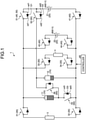
- FIG. 1 is a schematic diagram illustrating a configuration example of a power supply device 1 according to an embodiment.
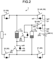
- FIG. 2 is a schematic diagram illustrating a configuration example of a part of the power supply device 1 according to the embodiment.
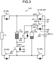
- FIG. 3 is a schematic diagram illustrating a configuration example of a series circuit P according to the embodiment.
- FIG. 4 is a schematic diagram illustrating a configuration example of a parallel circuit Q1 according to the embodiment.
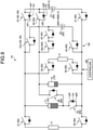
- FIG. 5 is a circuit diagram illustrating a configuration example of a part of the power supply device 1 according to the embodiment.
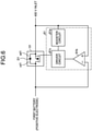
- FIG. 6 is a circuit diagram illustrating a configuration example of a voltage monitor circuit 61 according to the embodiment.
- FIG. 7 is a circuit diagram illustrating a configuration example of a voltage monitor circuit 63 according to the embodiment.
- the power supply device 1 is mounted on a vehicle and supplies power to load units such as a front power control unit (PCU) 3 and a rear PCU 4 provided in the vehicle.
- the vehicle is, for example, an electric vehicle such as an electric vehicle (EV), a hybrid electric vehicle (HEV), or a plug-in hybrid electric vehicle (PHEV).
- a connector of an external charger is connected to a 400 V inlet 21 of a vehicle, and a battery unit 10 is charged with power supplied from the external charger via the 400 V inlet 21.
- the power supply device 1 supplies the charged power to load units such as the front PCU 3 and the rear PCU 4.
- the power supply device 1 will be described in detail.
- the power supply device 1 includes a battery unit 10, a 400 V inlet 21 as an input unit, a main switching unit 30, a charge switching unit 40, a battery switching unit 50 as a switching unit, and a controller 60.
- the battery unit 10 is an assembly of storage batteries capable of charging and discharging DC power.
- the battery unit 10 is configured to include, for example, a first battery 11 and a second battery 12.
- the first battery 11 is a storage battery capable of charging and discharging DC power and has a plurality of battery cells.
- Each battery cell is constituted of a secondary battery capable of charging and discharging, and is constituted of, for example, a lithium ion battery.
- Each battery cell is connected in series with an adjacent battery cell.
- the second battery 12 is constituted in the same manner as the first battery 11.
- the second battery 12 is a storage battery capable of charging and discharging DC power, and has a plurality of battery cells.
- Each battery cell of the second battery 12 is constituted of a secondary battery capable of charging and discharging, and is constituted of, for example, a lithium ion battery.
- Each battery cell of the second battery 12 is connected in series with an adjacent battery cell.
- the second battery 12 has the same discharge capacity as the first battery 11.
- the battery unit 10 is switched to a series circuit P (see FIG. 3 ) connecting the first battery 11 and the second battery 12 in series, or a parallel circuit Q1 (see FIG. 4 ) connecting the first battery and the second battery in parallel.
- the battery unit 10 is connected to an external charger while being switched to the series circuit P or the parallel circuit Q1, and charges power supplied from the external charger.
- the battery unit 10 is also connected to the front PCU 3 and the rear PCU 4 while being switched to the series circuit P, and supplies the charged power to the front PCU 3 and the rear PCU 4.
- a charging inlet 20 is a charging port for inputting power supplied from an external charger.
- the charging inlet 20 is configured to include a 400 V inlet 21 and an 800 V inlet 22 as input units (see FIG. 1 ).
- the 400 V inlet 21 corresponds to an external charger having a voltage of 400 V.
- the 400 V inlet 21 is connected to the battery unit 10 via the charge switching unit 40 (charging relay 41, parallel-connected relay 51).
- the 400 V inlet 21 is electrically connected to an external charger when the connector of the external charger is inserted, and inputs power supplied from the external charger.
- the 400 V inlet 21 outputs the inputted power to the battery unit 10 via the charge switching unit 40.
- the 800 V inlet 22 corresponds to an external charger having a voltage of 800 V.
- the 800 V inlet 22 is connected to the battery unit 10 via the charge switching unit 40 (charging relays 43 and 44).
- the 800 V inlet 22 is electrically connected to the external charger when the connector of the external charger is inserted, and inputs power supplied from the external charger.
- the 800 V inlet 22 outputs the inputted power to the battery unit 10 via the charge switching unit 40.
- the main switching unit 30 energizes or interrupts the current flowing between the battery unit 10 and the front PCU 3 and the rear PCU 4.
- the main switching unit 30 is configured to include a main relay 31, a main relay 32, a main relay 33, and a main relay 34.
- the main relays 31 to 34 are, for example, an N-channel type metal-oxide-semiconductor field-effect transistor (MOSFET), and energizes or interrupts a current.
- MOSFET metal-oxide-semiconductor field-effect transistor
- the main relay 31 is provided between the positive electrode of the first battery 11 and the positive electrode of the front PCU 3.
- the main relay 31 is turned on by the controller 60 to energize the current flowing from the positive electrode of the first battery 11 to the front PCU 3.
- the main relay 31 is also turned off by the controller 60 to interrupt the current flowing from the positive electrode of the first battery 11 to the front PCU 3.
- the main relay 32 is provided between the negative electrode of the second battery 12 and the negative electrode of the front PCU 3.
- the main relay 32 is turned on by the controller 60 to energize the current flowing from the negative electrode of the second battery 12 to the front PCU 3.
- the main relay 32 is also turned off by the controller 60 to interrupt the current flowing from the negative electrode of the second battery 12 to the front PCU 3.
- the main relay 33 is provided between the positive electrode of the first battery 11 and the positive electrode of the rear PCU 4.
- the main relay 33 is turned on by the controller 60 to energize the current flowing from the positive electrode of the first battery 11 to the rear PCU 4.
- the main relay 33 is also turned off by the controller 60 to interrupt the current flowing from the positive electrode of the first battery 11 to the rear PCU 4.
- the main relay 34 is provided between the negative electrode of the second battery 12 and the negative electrode of the rear PCU 4.
- the main relay 34 is turned on by the controller 60 to energize the current flowing from the negative electrode of the second battery 12 to the rear PCU 4.
- the main relay 34 is also turned off by the controller 60 to interrupt the current flowing from the negative electrode of the second battery 12 to the rear PCU 4.
- the charge switching unit 40 energizes or interrupts the current flowing between the charging inlet 20 and the battery unit 10.
- the charge switching unit 40 is configured to include a charging relay 41, a parallel-connected relay 51, a charging relay 43, and a charging relay 44.
- the charging relays 41, 43 and 44, and the parallel-connected relay 51 are, for example, an N-channel type MOSFET, and energizes or interrupts a current.
- the parallel-connected relay 51 is provided between the positive electrode of the first battery 11 and the positive electrode of the 400 V inlet 21.
- the parallel-connected relay 51 is turned on by the controller 60 to energize the current flowing from the positive electrode of the first battery 11 to the positive electrode of the 400 V inlet 21.
- the parallel-connected relay 51 is also turned off by the controller 60 to interrupt the current flowing from the positive electrode of the first battery 11 to the positive electrode of the 400 V inlet 21.
- the charging relay 41 is provided between the negative electrodes of the first and second batteries 11 and 12 and the negative electrode of the 400 V inlet 21.
- the charging relay 41 is turned on by the controller 60 to energize the current flowing from the negative electrodes of the first and second batteries 11 and 12 to the negative electrode of the 400 V inlet 21.
- the charging relay 41 is also turned off by the controller 60 to interrupt the current flowing from the negative electrodes of the first and second batteries 11 and 12 to the negative electrode of the 400 V inlet 21.
- the charging relay 43 is provided between the positive electrode of the first battery 11 and the positive electrode of the 800 V inlet 22.
- the charging relay 43 is turned on by the controller 60 to energize the current flowing from the positive electrode of the first battery 11 to the positive electrode of the 800 V inlet 22.
- the charging relay 43 is also turned off by the controller 60 to interrupt the current flowing from the positive electrode of the first battery 11 to the positive electrode of the 800 V inlet 22.
- the charging relay 44 is provided between the negative electrode of the second battery 12 and the negative electrode of the 800 V inlet 22.
- the charging relay 44 is turned on by the controller 60 to energize the current flowing from the negative electrode of the second battery 12 to the negative electrode of the 800 V inlet 22.
- the charging relay 44 is also turned off by the controller 60 to interrupt the current flowing from the negative electrode of the second battery 12 to the negative electrode of the 800 V inlet 22.
- the battery switching unit 50 switches the connection between the first battery 11 and the second battery 12.
- the battery switching unit 50 is configured to include a parallel-connected relay 51, a parallel-connected relay 52, a parallel-connected relay 53, and a series-connected relay 56.
- the series-connected relay 56 is provided between the positive electrode of the second battery 12 and the negative electrode of the first battery 11.
- the series-connected relay 56 is turned on by the controller 60 to energize between the positive electrode of the second battery 12 and the negative electrode of the first battery 11.
- the series-connected relay 56 is also turned off by the controller 60 to interrupt between the positive electrode of the second battery 12 and the negative electrode of the first battery 11.
- the parallel-connected relay 51 is provided between the positive electrode of the first battery 11 and the positive electrode of the 400 V inlet 21.
- the parallel-connected relay 51 has a first parasitic diode D1, connects a first cathode terminal cd1 of the first parasitic diode D1 to the positive electrode of the first battery 11, and connects a first anode terminal ad1 of the first parasitic diode D1 to the positive electrode of the 400 V inlet 21 and the positive electrode of the second battery 12.
- the parallel-connected relay 51 is turned on by the controller 60 to energize between the positive electrode of the first battery 11 and both the positive electrode of the 400 V inlet 21 and the positive electrode of the second battery 12.
- the parallel-connected relay 51 is also turned off by the controller 60 to interrupt between the positive electrode of the first battery 11 and both the positive electrode of the 400 V inlet 21 and the positive electrode of the second battery 12.
- the parallel-connected relay 52 is provided between the positive electrode of the second battery 12 and the positive electrode of the 400 V inlet 21.
- the parallel-connected relay 52 has a second parasitic diode D2, connects a second cathode terminal cd2 of the second parasitic diode D2 to the positive electrode of the second battery 12, and connects a second anode terminal ad2 of the second parasitic diode D2 to the positive electrode of the 400 V inlet 21 and the positive electrode of the first battery 11.
- the parallel-connected relay 52 is turned on by the controller 60 to energize between the positive electrode of the second battery 12 and both the positive electrode of the 400 V inlet 21 and the positive electrode of the first battery 11.
- the parallel-connected relay 52 is also turned off by the controller 60 to interrupt between the positive electrode of the second battery 12 and both the positive electrode of the 400 V inlet 21 and the positive electrode of the first battery 11.
- the parallel-connected relay 53 is provided between the negative electrode of the first battery 11 and the negative electrode of the second battery 12.
- the parallel-connected relay 53 has a third parasitic diode D3.
- a third cathode terminal cd3 of the third parasitic diode D3 is connected to the negative electrode of the first battery 11 and connected to the positive electrode of the second battery 12 via the series-connected relay 56.
- a third anode terminal ad3 of the third parasitic diode D3 is connected to the negative electrode of the second battery 12 and connected to the negative electrode of the 400 V inlet 21 via the charging relay 41.
- the parallel-connected relay 53 is turned on by the controller 60 to energize between the negative electrode of the first battery 11 and both the negative electrode of the second battery 12 and the negative electrode of the 400 V inlet 21.
- the parallel-connected relay 53 is also turned off by the controller 60 to interrupt between the negative electrode of the first battery 11 and both the negative electrode of the second battery 12 and the negative electrode of the 400 V inlet 21.
- the battery switching unit 50 switches the parallel-connected relay 51, the parallel-connected relay 52, the parallel-connected relay 53, and the series-connected relay 56 to switch to the series circuit P connecting the first battery 11 and the second battery 12 in series, or to the parallel circuit Q1 connecting the first battery 11 and the second battery 12 in parallel.
- the battery switching unit 50 turns on the series-connected relay 56 and turns off the parallel-connected relay 51, the parallel-connected relay 52, and the parallel-connected relay 53, thereby forming the series circuit P connecting the first battery 11 and the second battery 12 in series.
- the battery switching unit 50 turns on the parallel-connected relay 51, the parallel-connected relay 52, and the parallel-connected relay 53, and turns off the series-connected relay 56, thereby forming the parallel circuit Q1 connecting the first battery 11 and the second battery 12 in parallel.
- the controller 60 controls the main switching unit 30, the charge switching unit 40, and the battery switching unit 50.
- the controller 60 is configured to include an electronic circuit mainly composed of a well-known microcomputer including a CPU, a ROM and a RAM constituting a storage unit, and an interface.
- the controller 60 controls the main switching unit 30 to energize or interrupt the current flowing between the battery unit 10 and both the front PCU 3 and the rear PCU 4.
- the controller 60 controls the charge switching unit 40 to energize or interrupt the current flowing between the 400 V inlet 21 or the 800 V inlet 22 and the battery unit 10.
- the controller 60 controls the battery switching unit 50 to switch the connection between the first battery 11 and the second battery 12 to the series circuit P or the parallel circuit Q1.
- the controller 60 is configured to include voltage monitor circuits 61 to 63 (see FIG. 5 ).
- the voltage monitor circuit 61 monitors the voltage of the parallel-connected relay 51.
- the voltage monitor circuit 61 controls the parallel-connected relay 51 based on voltages applied to the first cathode terminal cd1 and the first anode terminal ad1.
- the voltage monitor circuit 61 includes a booster circuit 61a, a comparator circuit 61b, and a driver circuit 61c.
- the booster circuit 61a is connected to the 400 V inlet 21 and the driver circuit 61c, and boosts the driver circuit 61c based on the power supplied from the 400 V inlet 21.
- the comparator circuit 61b outputs the comparison result of the voltage applied between the terminals of the parallel-connected relay 51.
- the comparator circuit 61b connects the positive electrode terminal to the first anode terminal ad1 of the first parasitic diode D1 and connects a negative electrode terminal to the first cathode terminal cd1 of the first parasitic diode D1.
- the comparator circuit 61b outputs the comparison result between the voltage applied to the first cathode terminal cd1 and the voltage applied to the first anode terminal ad1 to the driver circuit 61c.
- the comparator circuit 61b when the voltage applied to the first cathode terminal cd1 is less than the voltage applied to the first anode terminal ad1, the comparator circuit 61b outputs an ON signal for turning on the parallel-connected relay 51 to the driver circuit 61c.
- the comparator circuit 61b when the voltage applied to the first cathode terminal cd1 is equal to or higher than the voltage applied to the first anode terminal ad1, the comparator circuit 61b outputs an OFF signal for turning off the parallel-connected relay 51 to the driver circuit 61c.
- the driver circuit 61c turns on or off the parallel-connected relay 51.
- the driver circuit 61c is connected to the output terminal of the comparator circuit 61b and the gate terminal of the parallel-connected relay 51, and turns on or off the parallel-connected relay 51 based on the comparison result of the comparator circuit 61b. For example, when an ON signal is outputted from the comparator circuit 61b, the driver circuit 61c applies an ON voltage to the gate terminal of the parallel-connected relay 51 to turn on the parallel-connected relay 51. Thus, it is energized between the positive electrode of the first battery 11 and both the positive electrode of the 400 V inlet 21 and the positive electrode of the second battery 12.
- the driver circuit 61c applies an OFF voltage to the gate terminal of the parallel-connected relay 51 to turn off the parallel-connected relay 51.
- the positive electrode of the first battery 11, the positive electrode of the 400 V inlet 21 and the positive electrode of the second battery 12 are interrupted.
- a voltage monitor circuit 62 monitors the voltage of the parallel-connected relay 52.
- the voltage monitor circuit 62 has the same configuration and operation as the voltage monitor circuit 61.
- the voltage monitor circuit 62 controls the parallel-connected relay 52 based on voltages applied to the second cathode terminal cd2 and the second anode terminal ad2. For example, when the voltage applied to the second cathode terminal cd2 is less than the voltage applied to the second anode terminal ad2, the voltage monitor circuit 62 turns on the parallel-connected relay 52 to energize between the positive electrode of the second battery 12 and both the positive electrode of the 400 V inlet 21 and the positive electrode of the first battery 11.
- the voltage monitor circuit 62 turns off the parallel-connected relay 52 to interrupt between the positive electrode of the second battery 12 and both the positive electrode of the 400 V inlet 21 and the positive electrode of the first battery 11.
- the voltage monitor circuit 63 monitors the voltage of the parallel-connected relay 53.
- the voltage monitor circuit 63 has an offset power supply 63a, a comparator circuit 63b, an AND circuit 63c, and a driver circuit 63d.
- the offset power supply 63a is a power supply for applying a predetermined voltage (for example, 10 V) to the positive electrode of the comparator circuit 63b.
- the offset power supply 63a applies a predetermined voltage (for example, 10 V) to the side of the third anode terminal ad3 in order to turn on the parallel-connected relay 53, although there is no potential difference between the third cathode terminal cd3 and the third anode terminal ad3 of the parallel-connected relay 53.
- a predetermined voltage for example, 10 V
- the offset power supply 63a applies a predetermined voltage (for example, 10 V) to the side of the third anode terminal ad3 in order to satisfy the condition of turning on, when the potential difference between the third anode terminal ad3 and the third cathode terminal cd3 is zero and the voltage of the third anode terminal ad3 is higher than the voltage of the third cathode terminal cd3.
- a predetermined voltage for example, 10 V
- the comparator circuit 63b outputs the comparison result of the voltage applied between the terminals of the parallel-connected relay 53.
- the comparator circuit 63b connects the positive electrode terminal to the third anode terminal ad3 of the third parasitic diode D3 via the offset power supply 63a and connects the negative electrode terminal to the third cathode terminal cd3 of the third parasitic diode D3.
- the comparator circuit 63b outputs the comparison result between the voltage applied to the third cathode terminal cd3 and the voltage applied to the third anode terminal ad3 to the AND circuit 63c.
- the comparator circuit 63b when the voltage applied to the third cathode terminal cd3 is less than the voltage applied to the third anode terminal ad3, the comparator circuit 63b outputs an ON signal for turning on the parallel-connected relay 53 to the AND circuit 63c.
- the comparator circuit 63b when the voltage applied to the third cathode terminal cd3 is equal to or higher than the voltage applied to the third anode terminal ad3, the comparator circuit 63b outputs an OFF signal for turning off the parallel-connected relay 53 to the AND circuit 63c.
- the AND circuit 63c is a circuit for calculating the AND of the two signals.
- the AND circuit 63c calculates an AND of an external signal for turning on or off the parallel-connected relay 53 and an ON signal or an OFF signal outputted from the comparator circuit 63b.
- the external signal is a signal for preventing a short circuit by making the parallel-connected relay 53 in an OFF state before turning on the series-connected relay 56 when switching from the parallel circuit Q1 to the series circuit P.
- the AND circuit 63c outputs an ON signal for turning on the parallel-connected relay 53 to the driver circuit 63d when the external signal is an ON and the ON signal is outputted from the comparator circuit 63b.
- the AND circuit 63c outputs an OFF signal for turning off the parallel-connected relay 53 to the driver circuit 63d when at least one of the external signals and the signal outputted from the comparator circuit 63b is an OFF.
- the driver circuit 63d turns on or off the parallel-connected relay 53.
- the driver circuit 63d is connected to the output terminal of the AND circuit 63c and the gate terminal of the parallel-connected relay 53, and turns on or off the parallel-connected relay 53 based on the output result of the AND circuit 63c. For example, when an ON signal is outputted from the AND circuit 63c, the driver circuit 63d applies an ON voltage to the gate terminal of the parallel-connected relay 53 to turn on the parallel-connected relay 53. Thus, the positive electrode and the negative electrode of the second battery 12 are energized.
- the driver circuit 63d applies an OFF voltage to the gate terminal of the parallel-connected relay 53 to turn off the parallel-connected relay 53.
- the positive electrode and the negative electrode of the second battery 12 are interrupted.
- FIG. 8 is a flowchart illustrating an operation example of 400 V charging according to the embodiment.
- the controller 60 determines whether or not 400 V charging has been started (step S1). For example, when the voltage on the 400 V inlet 21 side is higher than the voltage on the battery unit 10 side in the parallel-connected relays 51 and 52, the controller 60 determines that the connector of the external charger is connected to the 400 V inlet 21 and charging is started.
- the controller 60 determines that charging is started.
- step S2 When 400 V charging is started (step S1; Yes), the controller 60 forms the parallel circuit Q1 (step S2). For example, the controller 60 turns on the parallel-connected relay 51, the parallel-connected relay 52 and the parallel-connected relay 53, and turns off the series-connected relay 56, thereby forming the parallel circuit Q1 connecting the first battery 11 and the second battery 12 in parallel.
- the controller 60 determines whether or not the current flows backward from the first battery 11 (step S3). For example, when the voltage applied to the first cathode terminal cd1 in the voltage monitor circuit 61 is equal to or higher than the voltage applied to the first anode terminal ad1, the controller 60 determines that the current flows backward from the first battery 11 (step S3; Yes), and turns off the parallel-connected relay 51 (step S4).
- step S3 when the voltage applied to the first cathode terminal cd1 is less than the voltage applied to the first anode terminal ad1, the controller 60 determines that the current does not flow backward from the first battery 11 (step S3; No), and continues to turn on the parallel-connected relay 51.
- the controller 60 determines whether or not the current flows backward from the second battery 12 (step S5). For example, when the voltage applied to the second cathode terminal cd2 in the voltage monitor circuit 62 is equal to or higher than the voltage applied to the second anode terminal ad2, the controller 60 determines that the current flows backward from the second battery 12 (step S5; Yes), and turns off the parallel-connected relay 52 (step S6). On the other hand, when the voltage applied to the second cathode terminal cd2 is less than the voltage applied to the second anode terminal ad2, the controller 60 determines that the current does not flow backward from the second battery 12 (step S5; No), and continues to turn on the parallel-connected relay 52.
- the controller 60 turns on the charge switching unit 40 (step S7).
- the controller 60 for example, turns on the charging relay 41 to charge the first and second batteries 11 and 12 constituting the parallel circuit Q (step S8).
- the controller 60 determines whether or not charging has been completed (step S9).
- the controller 60 when charging is completed (step S9; Yes), turns off the charge switching unit 40 to terminate the 400 V charging process.
- the controller 60 when charging has not been completed (step S9; No), returns to the above-described step S3 and determines again whether or not the current flows backward from the first battery 11.
- the controller 60 terminates the 400 V charging process.
- the power supply device 1 includes the first battery 11, the second battery 12, the battery switching unit 50, the charging inlet 20, and the controller 60.
- the first battery 11 is a storage battery mounted on a vehicle and capable of storing electric power.
- the second battery 12 is a storage battery mounted on said vehicle and capable of storing electric power.
- the battery switching unit 50 is a circuit capable of switching the series-connected relay 56, the parallel-connected relay 51, the parallel-connected relay 52 and the parallel-connected relay 53 to switch to a series circuit P connecting the first battery 11 and the second battery 12 in series or a parallel circuit Q1 connecting the first battery 11 and the second battery 12 in parallel.
- the charging inlet 20 is connected to an external charger to input power supplied from the external charger.
- the controller 60 controls the battery switching unit 50 to switch to the series circuit P or the parallel circuit Q1.
- the series-connected relay 56 is provided between the positive electrode of the second battery 12 and the negative electrode of the first battery 11, and energizes or interrupts between the positive electrode of the second battery 12 and the negative electrode of the first battery 11.
- the parallel-connected relay 51 has a first parasitic diode D1, connects the first cathode terminal cd1 of the first parasitic diode D1 to the positive electrode of the first battery 11, and connects the first anode terminal ad1 of the first parasitic diode D1 to the positive electrode of the charging inlet 20 to energize or interrupt between the positive electrode of the first battery 11 and the positive electrode of the charging inlet 20.
- the parallel-connected relay 52 has a second parasitic diode D2, connects the second cathode terminal cd2 of the second parasitic diode D2 to the positive electrode of the second battery 12, and connects the second anode terminal ad2 of the second parasitic diode D2 to the positive electrode of the charging inlet 20 to energize or interrupt between the positive electrode of the second battery 12 and the positive electrode of the charging inlet 20.
- the parallel-connected relay 53 is provided between the negative electrode of the first battery 11 and the negative electrode of the second battery 12, and energizes or interrupts between the negative electrode of the first battery 11 and the negative electrode of the second battery 12.
- the controller 60 controls the battery switching unit 50 to switch to the parallel circuit Q1, controls the parallel-connected relay 51 based on the voltages applied to the first cathode terminal cd1 and the first anode terminal ad1, and further controls the parallel-connected relay 52 based on the voltages applied to the second cathode terminal cd2 and the second anode terminal ad2.
- This configuration enables the power supply device 1 to inhibit the current (inrush current) flowing backward from one of the first battery 11 or the second battery 12 to the other when the battery is charged by forming the parallel circuit Q1 in a state where the charging rate of the first battery 11 is different from the charging rate of the second battery 12.
- the power supply device 1 since the power supply device 1 does not need to determine the order of turning on the relays as in the prior art, the complicated operation of the device can be reduced. Since the power supply device 1 reduces the reverse flow by the parallel-connected relays 51 and 52, the loss can be reduced as compared with the case of reducing the reverse flow by the conventional diode.
- the parallel-connected relay 51 since the parallel-connected relay 51 also functions as a relay for charging, an increase in the number of relays can be suppressed, and an increase in the size of the device can be suppressed.
- the series-connected relay 56 when the series-connected relay 56 is turned on, the voltage of the first cathode terminal cd1 becomes larger than the voltage of the first anode terminal ad1 and the parallel-connected relay 51 is turned off, so that the parallel-connected relay 51 and the series-connected relay 56 can be prevented from being turned on simultaneously and the short circuit of the first battery 11 can be prevented.
- the power supply device 1 can supply power to a load unit by forming a series circuit P. As a result, the power supply device 1 can be properly charged and discharged.
- the controller 60 when, in charging the first battery 11 and the second battery 12 constituting the parallel circuit Q1, the voltage applied to the first cathode terminal cd1 is less than the voltage applied to the first anode terminal ad1, the controller 60 turns on the parallel-connected relay 51 to energize between the positive electrode of the first battery 11 and the positive electrode of the charging inlet 20.
- the controller 60 when the voltage applied to the first cathode terminal cd1 is equal to or higher than the voltage applied to the first anode terminal ad1, the controller 60 turns off the parallel-connected relay 51 to interrupt between the positive electrode of the first battery 11 and the positive electrode of the charging inlet 20.
- the controller 60 turns on the parallel-connected relay 52 to energize between the positive electrode of the second battery 12 and the positive electrode of the charging inlet 20.
- the controller 60 turns off the parallel-connected relay 52 to interrupt between the positive electrode of the second battery 12 and the positive electrode of the charging inlet 20.
- This configuration enables the power supply device 1 to inhibit the current flowing backward from the positive electrode of the first battery 11 to the positive electrode of the second battery 12, even if the parallel circuit Q1 is formed, for example, when the charging rate of the first battery 11 is higher than the charging rate of the second battery 12. Further, even if the parallel circuit Q1 is formed when the charging rate of the second battery 12 is higher than the charging rate of the first battery 11, the power supply device 1 can inhibit the current flowing backward from the positive electrode of the second battery 12 to the positive electrode of the first battery 11.
- the parallel-connected relay 53 has a third parasitic diode D3, connects the third cathode terminal cd3 of the third parasitic diode D3 to the positive electrode of the second battery 12 via the series-connected relay 56, and connects the third anode terminal ad3 of the third parasitic diode D3 to the negative electrode of the second battery 12.
- the controller 60 turns on the parallel-connected relay 53 to energize between the positive electrode and the negative electrode of the second battery 12.
- the controller 60 turns off the parallel-connected relay 53 to interrupt between the positive electrode and the negative electrode of the second battery 12. This configuration enables the power supply device 1 to prevent the second battery 12 from short-circuiting.
- FIG. 9 is a schematic diagram illustrating a configuration example of a power supply device 1A according to a modification of the embodiment.
- the power supply device 1A differs from the power supply device 1 of the embodiment in that the power supply device 1A includes a common inlet 23 corresponding to external chargers having voltages of 400 V and 800 V.
- the charge switching unit 40 is further configured to include a charging relay 45.
- the charging relay 45 is provided between the positive electrode of the common inlet 23 and the positive electrode of the second battery 12.
- the charging relay 45 is turned on by the controller 60 when charging 400 V via the common inlet 23 to energize the current flowing from the positive electrode of the common inlet 23 to the positive electrode of the second battery 12.
- the charging relay 43 is turned off by the controller 60 when charging 800 V via the common inlet 23 to interrupt the current flowing from the positive electrode of the common inlet 23 to the positive electrode of the second battery 12.
- the battery switching unit 50 is further configured to include a parallel-connected relay 51a, a parallel-connected relay 52a, and a parallel-connected relay 53.
- the battery switching unit 50 can switch the parallel-connected relay 51a, the parallel-connected relay 52a, and the parallel-connected relay 53 to switch to a parallel circuit Q2 as a second parallel circuit connecting the first battery 11 and the second battery 12 in parallel.
- the battery switching unit 50 for example, turns on the parallel-connected relay 51a, the parallel-connected relay 52a, and the parallel-connected relay 53 and turns off the series-connected relay 56, thereby forming the parallel circuit Q2 connecting the first battery 11 and the second battery 12 in parallel.
- the controller 60 controls the battery switching unit 50, charges by one circuit of the parallel circuit Q1 or the parallel circuit Q2, and does not charge by the other circuit of the parallel circuit Q1 or the parallel circuit Q2.
- the controller 60 controls the battery switching unit 50 to form the parallel circuit Q1, charges by the parallel circuit Q1, and does not charge by the circuit of the parallel circuit Q2.
- the controller 60 controls the battery switching unit 50 to form the parallel circuit Q2, charges by the parallel circuit Q2, and does not charge by the circuit of the parallel circuit Q1.
- the battery switching unit 50 can switch the parallel-connected relay 51a, the parallel-connected relay 52a, and the parallel-connected relay 53 to switch to a parallel circuit Q2 connecting the first battery 11 and the second battery 12 in parallel.
- the controller 60 controls the battery switching unit 50, charges by one circuit of the parallel circuit Q1 or the parallel circuit Q2 and does not charge by the other circuit of the parallel circuit Q1 or the parallel circuit Q2.
- the power supply device 1A may be configured to include a common inlet 23 corresponding to external chargers having voltages of 400 V and 800 V.
- each relay is an N-channel type MOSFET, but is not limited thereto, and other switches may be used.
- the power supply device can inhibit a current flowing backward from one of the first battery and the second battery to the other when the battery is charged by forming a parallel circuit in a state where the charging rate of the first battery and the charging rate of the second battery are different, and thus enabling to charge and discharge properly.
Landscapes
- Engineering & Computer Science (AREA)
- Power Engineering (AREA)
- Transportation (AREA)
- Mechanical Engineering (AREA)
- Life Sciences & Earth Sciences (AREA)
- Sustainable Development (AREA)
- Sustainable Energy (AREA)
- Charge And Discharge Circuits For Batteries Or The Like (AREA)
- Secondary Cells (AREA)
- Electric Propulsion And Braking For Vehicles (AREA)
Claims (3)
- Stromversorgungsvorrichtung (1, 1A), die umfasst:eine erste Batterie (11), die an einem Fahrzeug angebracht ist und elektrische Energie speichern kann;eine zweite Batterie (12), die an dem Fahrzeug angebracht ist und elektrische Energie speichern kann;eine Schalt-Einheit (50), die einen in Reihe geschalteten Schalter (56), einen ersten parallel geschalteten Schalter (51), einen zweiten parallel geschalteten Schalter (52) und einen dritten parallel geschalteten Schalter (53) enthält, wobei die Schalt-Einheit (50) so ausgeführt ist, dass sie entweder eine Reihenschaltung (P), die die erste Batterie (11) und die zweite Batterie (12) in Reihe verbindet, oder eine erste Parallelschaltung (Q1) bildet, die die erste Batterie (11) und die zweite Batterie (12) parallel verbindet;eine erste Einleit-Einheit (21), die so ausgeführt ist, dass sie an eine externe Ladeeinrichtung angeschlossen wird und von der externen Ladeeinrichtung zugeführte elektrische Energie einleitet; sowieeine Steuerungseinrichtung (60), die so ausgeführt ist, dass sie die Schalt-Einheit (50) so steuert, dass sie zwischen der Reihenschaltung (P) und der ersten Parallelschaltung (Q1) umschaltet, wobeider in Reihe geschaltete Schalter (56) zwischen einer positiven Elektrode der zweiten Batterie (12) und einer negativen Elektrode der ersten Batterie (11) vorhanden ist,der erste parallel geschaltete Schalter (51) zwischen einer positiven Elektrode der ersten Batterie (11) und einer positiven Elektrode der ersten Einleit-Einheit (21) vorhanden ist und eine erste parasitäre Diode (D1) aufweist, wobei ein erster Kathodenanschluss (cd1) der ersten parasitären Diode (D1) mit der positiven Elektrode der ersten Batterie (11) verbunden ist, und ein erster Anodenanschluss (ad1) der ersten parasitären Diode (D1) mit der positiven Elektrode der ersten Einleit-Einheit (21) verbunden ist,der zweite parallel geschaltete Schalter (52) zwischen der positiven Elektrode der zweiten Batterie (12) und der positiven Elektrode der ersten Einleit-Einheit (21) vorhanden ist und eine zweite parasitäre Diode (D2) aufweist, wobei ein zweiter Kathodenanschluss (cd2) der zweiten parasitären Diode (D2) mit der positiven Elektrode der zweiten Batterie (12) verbunden ist, und ein zweiter Anodenanschluss (ad2) der zweiten parasitären Diode (D2) mit der positiven Elektrode der ersten Einleit-Einheit (21) verbunden ist,der dritte parallel geschaltete Schalter (53) zwischen der negativen Elektrode der ersten Batterie (11) und einer negativen Elektrode der zweiten Batterie (12) vorhanden ist, unddie Steuerungseinrichtung (60) so ausgeführt ist, dass sie die Schalt-Einheit (50) beim Laden der ersten Batterie (11) und der zweiten Batterie (12) so steuert, dass sie auf die erste Parallelschaltung (Q1) umschaltet,wobeidie Steuerungseinrichtung (60) so ausgeführt ist, dass sie, wenn beim Laden der ersten Batterie (11) und der zweiten Batterie (12) die an den ersten Kathodenanschluss (cd1) angelegte Spannung niedriger ist als die an den ersten Anodenanschluss (ad1) angelegte Spannung, den ersten parallel geschalteten Schalter (51) schließt, um zwischen der positiven Elektrode der ersten Batterie (11) und der positiven Elektrode der ersten Einleit-Einheit (21) Spannung anzulegen,die Steuerungseinrichtung (60) so ausgeführt ist, dass sie, wenn die an den ersten Kathodenanschluss (cd1) angelegte Spannung genauso hoch ist wie oder höher als die an den ersten Anodenanschluss (ad1) angelegte Spannung, den ersten parallel geschalteten Schalter (51) öffnet, um einen zwischen der positiven Elektrode der ersten Batterie (11) und der positiven Elektrode der ersten Einleit-Einheit (21) fließenden Strom zu unterbrechen,die Steuerungseinrichtung (60) so ausgeführt ist, dass sie, wenn die an den zweiten Kathodenanschluss (cd2) angelegte Spannung niedriger ist als die an den zweiten Anodenanschluss (ad2) angelegte Spannung, den zweiten parallel geschalteten Schalter (52) schließt, um zwischen der positiven Elektrode der zweiten Batterie (12) und der positiven Elektrode der ersten Einleit-Einheit (21) Spannung anzulegen, unddie Steuerungseinrichtung (60) so ausgeführt ist, dass sie, wenn die an den zweiten Kathodenanschluss (cd2) angelegte Spannung genauso hoch ist wie oder höher als die an den zweiten Anodenanschluss (ad2) angelegte Spannung, den zweiten parallel geschalteten Schalter (52) öffnet, um einen zwischen der positiven Elektrode der zweiten Batterie (12) und der positiven Elektrode der ersten Einleit-Einheit (21) fließenden Strom zu unterbrechen.
- Stromversorgungsvorrichtung (1, 1A) nach Anspruch 1, wobeider dritte parallel geschaltete Schalter (53) eine dritte parasitäre Diode (D3) aufweist, ein dritter Kathodenanschluss (cd3) der dritten parasitären Diode (D3) über den in Reihe geschalteten Schalter (56) mit der positiven Elektrode der zweiten Batterie (12) verbunden ist, und ein dritter Anodenanschluss (ad3) der dritten parasitären Diode (D3) mit der negativen Elektrode der zweiten Batterie (12) verbunden ist,die Steuerungseinrichtung (60) so ausgeführt ist, dass sie, wenn eine an den dritten Kathodenanschluss (cd3) angelegte Spannung niedriger ist als eine an den dritten Anodenanschluss (ad3) angelegte Spannung, den dritten parallel geschalteten Schalter (53) schließt, um zwischen der positiven Elektrode und der negativen Elektrode der zweiten Batterie (12) Spannung anzulegen, unddie Steuerungseinrichtung (60) so ausgeführt ist, dass sie, wenn die an den dritten Kathodenanschluss (cd3) angelegte Spannung genauso hoch ist wie oder höher als die an den dritten Anodenanschluss (ad3) angelegte Spannung, den dritten parallel geschalteten Schalter (53) öffnet, um einen zwischen der positiven Elektrode und der negativen Elektrode der zweiten Batterie (12) fließenden Strom zu unterbrechen.
- Stromversorgungsvorrichtung (1A) nach Anspruch 1 oder 2, die des Weiteren umfasst:eine zweite Einleit-Einheit (23), die so ausgeführt ist, dass sie an eine externe Ladeeinrichtung angeschlossen wird und von der externen Ladeeinrichtung zugeführte elektrische Energie einleitet,wobei die Schalt-Einheit (50) des Weiteren einen vierten parallel geschalteten Schalter (51a), einen fünften parallel geschalteten Schalter (52a) und den dritten parallel geschalteten Schalter (53) umfasst, die eine zweite Parallelschaltung (Q2) bilden, die die erste Batterie (11) und die zweite Batterie (12) parallel verbindet, undder vierte parallel geschaltete Schalter (51a) zwischen einer positiven Elektrode der ersten Batterie (11) und einer positiven Elektrode der zweiten Einleit-Einheit (23) vorhanden ist und eine vierte parasitäre Diode aufweist, wobei ein erster Kathodenanschluss der vierten parasitären Diode mit der positiven Elektrode der ersten Batterie (11) verbunden ist, und ein erster Anodenanschluss der vierten parasitären Diode mit der positiven Elektrode der zweiten Einleit-Einheit (23) verbunden ist,der fünfte parallel geschaltete Schalter (52a) zwischen der positiven Elektrode der zweiten Batterie (12) und der positiven Elektrode der zweiten Einleit-Einheit (23) vorhanden ist und eine fünfte parasitäre Diode aufweist, wobei ein zweiter Kathodenanschluss der fünften parasitären Diode mit der positiven Elektrode der zweiten Batterie (12) verbunden ist, und ein zweiter Anodenanschluss der fünften parasitären Diode mit der positiven Elektrode der zweiten Einleit-Einheit (23) verbunden ist,die Steuerungseinrichtung (60) so ausgeführt ist, dass sie beim Laden der ersten Batterie (11) und der zweiten Batterie (12) die Schalt-Einheit (50) so steuert, dass sie über einen Stromkreis der ersten Parallelschaltung (Q1) oder der zweiten Parallelschaltung (Q2) lädt und über einen anderen Stromkreis der ersten Parallelschaltung (Q1) oder der zweiten Parallelschaltung (Q2) nicht lädt.
Applications Claiming Priority (1)
| Application Number | Priority Date | Filing Date | Title |
|---|---|---|---|
| JP2019129103A JP7034560B2 (ja) | 2019-07-11 | 2019-07-11 | 電源装置 |
Publications (2)
| Publication Number | Publication Date |
|---|---|
| EP3764508A1 EP3764508A1 (de) | 2021-01-13 |
| EP3764508B1 true EP3764508B1 (de) | 2022-02-23 |
Family
ID=71143527
Family Applications (1)
| Application Number | Title | Priority Date | Filing Date |
|---|---|---|---|
| EP20181970.3A Active EP3764508B1 (de) | 2019-07-11 | 2020-06-24 | Stromversorgungsvorrichtung |
Country Status (4)
| Country | Link |
|---|---|
| US (1) | US11186202B2 (de) |
| EP (1) | EP3764508B1 (de) |
| JP (1) | JP7034560B2 (de) |
| CN (1) | CN112217245B (de) |
Families Citing this family (12)
| Publication number | Priority date | Publication date | Assignee | Title |
|---|---|---|---|---|
| US11016140B1 (en) * | 2018-10-31 | 2021-05-25 | Wisk Aero Llc | Battery diode fault monitoring |
| DE102020105543A1 (de) | 2020-03-02 | 2021-09-02 | Audi Aktiengesellschaft | Batteriesystem für ein Kraftfahrzeug sowie Kraftfahrzeug, System und Betriebsverfahren für das Batteriesystem |
| CN113183780B (zh) * | 2021-06-02 | 2025-06-17 | 浙江英飞特新能源科技有限公司 | 一种储能充电换电系统 |
| US11777334B2 (en) * | 2021-11-11 | 2023-10-03 | Beta Air, Llc | System for charging multiple power sources and monitoring diode currents for faults |
| CN114506225B (zh) * | 2022-02-22 | 2022-09-13 | 贺洪芝 | 无功率输出中断的电池串并联切换主电路及系统、方法 |
| CN118414762A (zh) * | 2022-05-25 | 2024-07-30 | 宁德时代新能源科技股份有限公司 | 电池系统及其控制方法、用电装置、电子设备 |
| CN115765448B (zh) * | 2022-11-09 | 2025-07-22 | 绍兴合田新能源有限公司 | 一种dc电源的串并联自动切换控制电路 |
| US12515557B2 (en) * | 2023-01-26 | 2026-01-06 | GM Global Technology Operations LLC | Electric vehicle recharge control |
| CN116811666B (zh) * | 2023-08-17 | 2024-05-14 | 广州巨湾技研有限公司 | 动力电池系统放电控制方法、系统、电子设备和存储介质 |
| JP2025080653A (ja) | 2023-11-14 | 2025-05-26 | トヨタ自動車株式会社 | 電力供給システム |
| CN118100350A (zh) * | 2024-01-08 | 2024-05-28 | 福建南平南孚电池有限公司 | 一种电池充电器 |
| JP7731460B1 (ja) * | 2024-03-01 | 2025-08-29 | 本田技研工業株式会社 | 電源装置及び電源装置の制御方法 |
Family Cites Families (15)
| Publication number | Priority date | Publication date | Assignee | Title |
|---|---|---|---|---|
| US6087803A (en) * | 1997-05-23 | 2000-07-11 | Sony Corporation | Battery pack, electronic equipment system and method of detecting loading of battery pack technical field |
| JP2001520858A (ja) * | 1998-01-31 | 2001-10-30 | モトローラ・インコーポレイテッド | リチウム方式の再充電バッテリのための過充電保護装置および方法 |
| US20060186857A1 (en) * | 2005-02-23 | 2006-08-24 | Saft | Rechargeable battery with charge control |
| JP2010088202A (ja) * | 2008-09-30 | 2010-04-15 | Toshiba Corp | 電池ユニットおよびこれを用いた電池システム |
| DE102009046501A1 (de) * | 2009-11-06 | 2011-05-12 | SB LiMotive Company Ltd., Suwon | Batteriesystem mit DC/DC-Umsetzern |
| JP2013051831A (ja) * | 2011-08-31 | 2013-03-14 | Toyota Motor Corp | 電動車両の電源制御装置 |
| DE212013000040U1 (de) * | 2012-07-30 | 2014-07-21 | Obshchestvo s organichennoy otvetstvennostyu "sistemy" upravlenia khraneniem energii" | Rangsteuerungssystem für die Elektroengergiespeicherbatterien |
| KR101450717B1 (ko) * | 2013-01-18 | 2014-10-16 | 포항공과대학교 산학협력단 | 엘씨 직렬공진을 이용한 배터리셀 밸런싱 회로 |
| JP6373662B2 (ja) * | 2014-07-04 | 2018-08-15 | 株式会社マキタ | バッテリパック |
| DE102016008052A1 (de) | 2016-07-01 | 2017-02-16 | Daimler Ag | Energiespeichereinrichtung für einen Kraftwagen |
| JP6779708B2 (ja) | 2016-08-25 | 2020-11-04 | 矢崎総業株式会社 | 急速充電装置 |
| WO2018123391A1 (ja) * | 2016-12-28 | 2018-07-05 | 本田技研工業株式会社 | 電気回路、及び診断方法 |
| DE102017206834A1 (de) | 2017-04-24 | 2018-10-25 | Robert Bosch Gmbh | Schaltungsanordnung und Ladeverfahren für ein elektrisches Energiespeichersystem |
| KR20180133018A (ko) * | 2017-06-02 | 2018-12-13 | 현대자동차주식회사 | 차량용 배터리 시스템 및 제어방법 |
| JP7009915B2 (ja) * | 2017-10-27 | 2022-01-26 | 株式会社デンソー | 蓄電システム |
-
2019
- 2019-07-11 JP JP2019129103A patent/JP7034560B2/ja active Active
-
2020
- 2020-06-24 EP EP20181970.3A patent/EP3764508B1/de active Active
- 2020-07-08 US US16/924,136 patent/US11186202B2/en active Active
- 2020-07-09 CN CN202010656175.3A patent/CN112217245B/zh active Active
Also Published As
| Publication number | Publication date |
|---|---|
| EP3764508A1 (de) | 2021-01-13 |
| JP2021016234A (ja) | 2021-02-12 |
| CN112217245B (zh) | 2024-04-26 |
| CN112217245A (zh) | 2021-01-12 |
| US11186202B2 (en) | 2021-11-30 |
| US20210009005A1 (en) | 2021-01-14 |
| JP7034560B2 (ja) | 2022-03-14 |
Similar Documents
| Publication | Publication Date | Title |
|---|---|---|
| EP3764508B1 (de) | Stromversorgungsvorrichtung | |
| US20240186803A1 (en) | Switching assembly and charging method for an electrical energy storage system | |
| US10967746B2 (en) | Vehicle | |
| CN113258632B (zh) | 电源装置 | |
| KR20140014226A (ko) | 배터리용 충전 밸런싱 시스템 | |
| US11462919B2 (en) | Secondary battery system and connection circuit | |
| JP5187406B2 (ja) | 補機バッテリ充電装置 | |
| US20150069960A1 (en) | Auxiliary Battery Charging Apparatus | |
| US11691536B2 (en) | Power system for a vehicle | |
| US20210028642A1 (en) | Electrical energy storage system and method for operating same | |
| JP2009148110A (ja) | 充放電器とこれを用いた電源装置 | |
| US20250015607A1 (en) | Power supply device | |
| US12184098B2 (en) | Power supply device | |
| KR102796089B1 (ko) | 배터리 관리 시스템 및 밸런싱 방법 | |
| JP7337567B2 (ja) | 電源装置 | |
| JP2018170927A (ja) | 電池パックの放電制御装置 | |
| CN212435391U (zh) | 一种电池双层保护电路以及电池装置 | |
| EP4697556A1 (de) | System und verfahren zur steuerung des ladens und entladens einer batterie | |
| EP4568058A1 (de) | Elektrisches stromversorgungssystem mit lademöglichkeit für zwei verschiedene parallel geschaltete batterien | |
| US20260036637A1 (en) | Battery unit voltage detection device | |
| US20230391228A1 (en) | Power supply device | |
| JP7422568B2 (ja) | 電池モジュール | |
| JP2022046365A (ja) | 二次電池システム |
Legal Events
| Date | Code | Title | Description |
|---|---|---|---|
| PUAI | Public reference made under article 153(3) epc to a published international application that has entered the european phase |
Free format text: ORIGINAL CODE: 0009012 |
|
| STAA | Information on the status of an ep patent application or granted ep patent |
Free format text: STATUS: REQUEST FOR EXAMINATION WAS MADE |
|
| 17P | Request for examination filed |
Effective date: 20200624 |
|
| AK | Designated contracting states |
Kind code of ref document: A1 Designated state(s): AL AT BE BG CH CY CZ DE DK EE ES FI FR GB GR HR HU IE IS IT LI LT LU LV MC MK MT NL NO PL PT RO RS SE SI SK SM TR |
|
| AX | Request for extension of the european patent |
Extension state: BA ME |
|
| GRAP | Despatch of communication of intention to grant a patent |
Free format text: ORIGINAL CODE: EPIDOSNIGR1 |
|
| STAA | Information on the status of an ep patent application or granted ep patent |
Free format text: STATUS: GRANT OF PATENT IS INTENDED |
|
| INTG | Intention to grant announced |
Effective date: 20211213 |
|
| RAP3 | Party data changed (applicant data changed or rights of an application transferred) |
Owner name: YAZAKI CORPORATION |
|
| GRAS | Grant fee paid |
Free format text: ORIGINAL CODE: EPIDOSNIGR3 |
|
| GRAA | (expected) grant |
Free format text: ORIGINAL CODE: 0009210 |
|
| STAA | Information on the status of an ep patent application or granted ep patent |
Free format text: STATUS: THE PATENT HAS BEEN GRANTED |
|
| AK | Designated contracting states |
Kind code of ref document: B1 Designated state(s): AL AT BE BG CH CY CZ DE DK EE ES FI FR GB GR HR HU IE IS IT LI LT LU LV MC MK MT NL NO PL PT RO RS SE SI SK SM TR |
|
| REG | Reference to a national code |
Ref country code: GB Ref legal event code: FG4D |
|
| REG | Reference to a national code |
Ref country code: CH Ref legal event code: EP |
|
| REG | Reference to a national code |
Ref country code: DE Ref legal event code: R096 Ref document number: 602020001946 Country of ref document: DE |
|
| REG | Reference to a national code |
Ref country code: AT Ref legal event code: REF Ref document number: 1471187 Country of ref document: AT Kind code of ref document: T Effective date: 20220315 |
|
| REG | Reference to a national code |
Ref country code: IE Ref legal event code: FG4D |
|
| REG | Reference to a national code |
Ref country code: LT Ref legal event code: MG9D |
|
| REG | Reference to a national code |
Ref country code: NL Ref legal event code: MP Effective date: 20220223 |
|
| REG | Reference to a national code |
Ref country code: AT Ref legal event code: MK05 Ref document number: 1471187 Country of ref document: AT Kind code of ref document: T Effective date: 20220223 |
|
| PG25 | Lapsed in a contracting state [announced via postgrant information from national office to epo] |
Ref country code: SE Free format text: LAPSE BECAUSE OF FAILURE TO SUBMIT A TRANSLATION OF THE DESCRIPTION OR TO PAY THE FEE WITHIN THE PRESCRIBED TIME-LIMIT Effective date: 20220223 Ref country code: RS Free format text: LAPSE BECAUSE OF FAILURE TO SUBMIT A TRANSLATION OF THE DESCRIPTION OR TO PAY THE FEE WITHIN THE PRESCRIBED TIME-LIMIT Effective date: 20220223 Ref country code: PT Free format text: LAPSE BECAUSE OF FAILURE TO SUBMIT A TRANSLATION OF THE DESCRIPTION OR TO PAY THE FEE WITHIN THE PRESCRIBED TIME-LIMIT Effective date: 20220623 Ref country code: NO Free format text: LAPSE BECAUSE OF FAILURE TO SUBMIT A TRANSLATION OF THE DESCRIPTION OR TO PAY THE FEE WITHIN THE PRESCRIBED TIME-LIMIT Effective date: 20220523 Ref country code: NL Free format text: LAPSE BECAUSE OF FAILURE TO SUBMIT A TRANSLATION OF THE DESCRIPTION OR TO PAY THE FEE WITHIN THE PRESCRIBED TIME-LIMIT Effective date: 20220223 Ref country code: LT Free format text: LAPSE BECAUSE OF FAILURE TO SUBMIT A TRANSLATION OF THE DESCRIPTION OR TO PAY THE FEE WITHIN THE PRESCRIBED TIME-LIMIT Effective date: 20220223 Ref country code: HR Free format text: LAPSE BECAUSE OF FAILURE TO SUBMIT A TRANSLATION OF THE DESCRIPTION OR TO PAY THE FEE WITHIN THE PRESCRIBED TIME-LIMIT Effective date: 20220223 Ref country code: ES Free format text: LAPSE BECAUSE OF FAILURE TO SUBMIT A TRANSLATION OF THE DESCRIPTION OR TO PAY THE FEE WITHIN THE PRESCRIBED TIME-LIMIT Effective date: 20220223 Ref country code: BG Free format text: LAPSE BECAUSE OF FAILURE TO SUBMIT A TRANSLATION OF THE DESCRIPTION OR TO PAY THE FEE WITHIN THE PRESCRIBED TIME-LIMIT Effective date: 20220523 |
|
| PG25 | Lapsed in a contracting state [announced via postgrant information from national office to epo] |
Ref country code: PL Free format text: LAPSE BECAUSE OF FAILURE TO SUBMIT A TRANSLATION OF THE DESCRIPTION OR TO PAY THE FEE WITHIN THE PRESCRIBED TIME-LIMIT Effective date: 20220223 Ref country code: LV Free format text: LAPSE BECAUSE OF FAILURE TO SUBMIT A TRANSLATION OF THE DESCRIPTION OR TO PAY THE FEE WITHIN THE PRESCRIBED TIME-LIMIT Effective date: 20220223 Ref country code: GR Free format text: LAPSE BECAUSE OF FAILURE TO SUBMIT A TRANSLATION OF THE DESCRIPTION OR TO PAY THE FEE WITHIN THE PRESCRIBED TIME-LIMIT Effective date: 20220524 Ref country code: FI Free format text: LAPSE BECAUSE OF FAILURE TO SUBMIT A TRANSLATION OF THE DESCRIPTION OR TO PAY THE FEE WITHIN THE PRESCRIBED TIME-LIMIT Effective date: 20220223 Ref country code: AT Free format text: LAPSE BECAUSE OF FAILURE TO SUBMIT A TRANSLATION OF THE DESCRIPTION OR TO PAY THE FEE WITHIN THE PRESCRIBED TIME-LIMIT Effective date: 20220223 |
|
| PG25 | Lapsed in a contracting state [announced via postgrant information from national office to epo] |
Ref country code: IS Free format text: LAPSE BECAUSE OF FAILURE TO SUBMIT A TRANSLATION OF THE DESCRIPTION OR TO PAY THE FEE WITHIN THE PRESCRIBED TIME-LIMIT Effective date: 20220623 |
|
| PG25 | Lapsed in a contracting state [announced via postgrant information from national office to epo] |
Ref country code: SM Free format text: LAPSE BECAUSE OF FAILURE TO SUBMIT A TRANSLATION OF THE DESCRIPTION OR TO PAY THE FEE WITHIN THE PRESCRIBED TIME-LIMIT Effective date: 20220223 Ref country code: SK Free format text: LAPSE BECAUSE OF FAILURE TO SUBMIT A TRANSLATION OF THE DESCRIPTION OR TO PAY THE FEE WITHIN THE PRESCRIBED TIME-LIMIT Effective date: 20220223 Ref country code: RO Free format text: LAPSE BECAUSE OF FAILURE TO SUBMIT A TRANSLATION OF THE DESCRIPTION OR TO PAY THE FEE WITHIN THE PRESCRIBED TIME-LIMIT Effective date: 20220223 Ref country code: EE Free format text: LAPSE BECAUSE OF FAILURE TO SUBMIT A TRANSLATION OF THE DESCRIPTION OR TO PAY THE FEE WITHIN THE PRESCRIBED TIME-LIMIT Effective date: 20220223 Ref country code: DK Free format text: LAPSE BECAUSE OF FAILURE TO SUBMIT A TRANSLATION OF THE DESCRIPTION OR TO PAY THE FEE WITHIN THE PRESCRIBED TIME-LIMIT Effective date: 20220223 Ref country code: CZ Free format text: LAPSE BECAUSE OF FAILURE TO SUBMIT A TRANSLATION OF THE DESCRIPTION OR TO PAY THE FEE WITHIN THE PRESCRIBED TIME-LIMIT Effective date: 20220223 |
|
| REG | Reference to a national code |
Ref country code: DE Ref legal event code: R097 Ref document number: 602020001946 Country of ref document: DE |
|
| PG25 | Lapsed in a contracting state [announced via postgrant information from national office to epo] |
Ref country code: AL Free format text: LAPSE BECAUSE OF FAILURE TO SUBMIT A TRANSLATION OF THE DESCRIPTION OR TO PAY THE FEE WITHIN THE PRESCRIBED TIME-LIMIT Effective date: 20220223 |
|
| PLBE | No opposition filed within time limit |
Free format text: ORIGINAL CODE: 0009261 |
|
| STAA | Information on the status of an ep patent application or granted ep patent |
Free format text: STATUS: NO OPPOSITION FILED WITHIN TIME LIMIT |
|
| PG25 | Lapsed in a contracting state [announced via postgrant information from national office to epo] |
Ref country code: MC Free format text: LAPSE BECAUSE OF FAILURE TO SUBMIT A TRANSLATION OF THE DESCRIPTION OR TO PAY THE FEE WITHIN THE PRESCRIBED TIME-LIMIT Effective date: 20220223 |
|
| 26N | No opposition filed |
Effective date: 20221124 |
|
| REG | Reference to a national code |
Ref country code: BE Ref legal event code: MM Effective date: 20220630 |
|
| PG25 | Lapsed in a contracting state [announced via postgrant information from national office to epo] |
Ref country code: SI Free format text: LAPSE BECAUSE OF FAILURE TO SUBMIT A TRANSLATION OF THE DESCRIPTION OR TO PAY THE FEE WITHIN THE PRESCRIBED TIME-LIMIT Effective date: 20220223 |
|
| PG25 | Lapsed in a contracting state [announced via postgrant information from national office to epo] |
Ref country code: LU Free format text: LAPSE BECAUSE OF NON-PAYMENT OF DUE FEES Effective date: 20220624 Ref country code: IE Free format text: LAPSE BECAUSE OF NON-PAYMENT OF DUE FEES Effective date: 20220624 Ref country code: FR Free format text: LAPSE BECAUSE OF NON-PAYMENT OF DUE FEES Effective date: 20220630 |
|
| PG25 | Lapsed in a contracting state [announced via postgrant information from national office to epo] |
Ref country code: BE Free format text: LAPSE BECAUSE OF NON-PAYMENT OF DUE FEES Effective date: 20220630 |
|
| PG25 | Lapsed in a contracting state [announced via postgrant information from national office to epo] |
Ref country code: IT Free format text: LAPSE BECAUSE OF FAILURE TO SUBMIT A TRANSLATION OF THE DESCRIPTION OR TO PAY THE FEE WITHIN THE PRESCRIBED TIME-LIMIT Effective date: 20220223 |
|
| REG | Reference to a national code |
Ref country code: CH Ref legal event code: PL |
|
| PG25 | Lapsed in a contracting state [announced via postgrant information from national office to epo] |
Ref country code: MK Free format text: LAPSE BECAUSE OF FAILURE TO SUBMIT A TRANSLATION OF THE DESCRIPTION OR TO PAY THE FEE WITHIN THE PRESCRIBED TIME-LIMIT Effective date: 20220223 Ref country code: CY Free format text: LAPSE BECAUSE OF FAILURE TO SUBMIT A TRANSLATION OF THE DESCRIPTION OR TO PAY THE FEE WITHIN THE PRESCRIBED TIME-LIMIT Effective date: 20220223 Ref country code: CH Free format text: LAPSE BECAUSE OF NON-PAYMENT OF DUE FEES Effective date: 20230630 |
|
| PG25 | Lapsed in a contracting state [announced via postgrant information from national office to epo] |
Ref country code: HU Free format text: LAPSE BECAUSE OF FAILURE TO SUBMIT A TRANSLATION OF THE DESCRIPTION OR TO PAY THE FEE WITHIN THE PRESCRIBED TIME-LIMIT; INVALID AB INITIO Effective date: 20200624 |
|
| PG25 | Lapsed in a contracting state [announced via postgrant information from national office to epo] |
Ref country code: MT Free format text: LAPSE BECAUSE OF FAILURE TO SUBMIT A TRANSLATION OF THE DESCRIPTION OR TO PAY THE FEE WITHIN THE PRESCRIBED TIME-LIMIT Effective date: 20220223 |
|
| GBPC | Gb: european patent ceased through non-payment of renewal fee |
Effective date: 20240624 |
|
| PG25 | Lapsed in a contracting state [announced via postgrant information from national office to epo] |
Ref country code: GB Free format text: LAPSE BECAUSE OF NON-PAYMENT OF DUE FEES Effective date: 20240624 |
|
| PGFP | Annual fee paid to national office [announced via postgrant information from national office to epo] |
Ref country code: DE Payment date: 20250429 Year of fee payment: 6 |
|
| PG25 | Lapsed in a contracting state [announced via postgrant information from national office to epo] |
Ref country code: TR Free format text: LAPSE BECAUSE OF FAILURE TO SUBMIT A TRANSLATION OF THE DESCRIPTION OR TO PAY THE FEE WITHIN THE PRESCRIBED TIME-LIMIT Effective date: 20220223 |