EP3764484A2 - Elektrische verbindungsanordnung und elektrische vorrichtung - Google Patents
Elektrische verbindungsanordnung und elektrische vorrichtung Download PDFInfo
- Publication number
- EP3764484A2 EP3764484A2 EP20180982.9A EP20180982A EP3764484A2 EP 3764484 A2 EP3764484 A2 EP 3764484A2 EP 20180982 A EP20180982 A EP 20180982A EP 3764484 A2 EP3764484 A2 EP 3764484A2
- Authority
- EP
- European Patent Office
- Prior art keywords
- electrical connection
- contact pad
- terminal
- connection module
- contact
- Prior art date
- Legal status (The legal status is an assumption and is not a legal conclusion. Google has not performed a legal analysis and makes no representation as to the accuracy of the status listed.)
- Pending
Links
Images




Classifications
-
- H—ELECTRICITY
- H01—ELECTRIC ELEMENTS
- H01R—ELECTRICALLY-CONDUCTIVE CONNECTIONS; STRUCTURAL ASSOCIATIONS OF A PLURALITY OF MUTUALLY-INSULATED ELECTRICAL CONNECTING ELEMENTS; COUPLING DEVICES; CURRENT COLLECTORS
- H01R13/00—Details of coupling devices of the kinds covered by groups H01R12/70 or H01R24/00 - H01R33/00
- H01R13/66—Structural association with built-in electrical component
- H01R13/70—Structural association with built-in electrical component with built-in switch
- H01R13/703—Structural association with built-in electrical component with built-in switch operated by engagement or disengagement of coupling parts, e.g. dual-continuity coupling part
- H01R13/7036—Structural association with built-in electrical component with built-in switch operated by engagement or disengagement of coupling parts, e.g. dual-continuity coupling part the switch being in series with coupling part, e.g. dead coupling, explosion proof coupling
- H01R13/7037—Structural association with built-in electrical component with built-in switch operated by engagement or disengagement of coupling parts, e.g. dual-continuity coupling part the switch being in series with coupling part, e.g. dead coupling, explosion proof coupling making use of a magnetically operated switch
-
- H—ELECTRICITY
- H01—ELECTRIC ELEMENTS
- H01R—ELECTRICALLY-CONDUCTIVE CONNECTIONS; STRUCTURAL ASSOCIATIONS OF A PLURALITY OF MUTUALLY-INSULATED ELECTRICAL CONNECTING ELEMENTS; COUPLING DEVICES; CURRENT COLLECTORS
- H01R33/00—Coupling devices specially adapted for supporting apparatus and having one part acting as a holder providing support and electrical connection via a counterpart which is structurally associated with the apparatus, e.g. lamp holders; Separate parts thereof
- H01R33/945—Holders with built-in electrical component
- H01R33/96—Holders with built-in electrical component with switch operated by engagement or disengagement of coupling
-
- H—ELECTRICITY
- H01—ELECTRIC ELEMENTS
- H01R—ELECTRICALLY-CONDUCTIVE CONNECTIONS; STRUCTURAL ASSOCIATIONS OF A PLURALITY OF MUTUALLY-INSULATED ELECTRICAL CONNECTING ELEMENTS; COUPLING DEVICES; CURRENT COLLECTORS
- H01R13/00—Details of coupling devices of the kinds covered by groups H01R12/70 or H01R24/00 - H01R33/00
- H01R13/62—Means for facilitating engagement or disengagement of coupling parts or for holding them in engagement
- H01R13/6205—Two-part coupling devices held in engagement by a magnet
-
- H—ELECTRICITY
- H01—ELECTRIC ELEMENTS
- H01R—ELECTRICALLY-CONDUCTIVE CONNECTIONS; STRUCTURAL ASSOCIATIONS OF A PLURALITY OF MUTUALLY-INSULATED ELECTRICAL CONNECTING ELEMENTS; COUPLING DEVICES; CURRENT COLLECTORS
- H01R13/00—Details of coupling devices of the kinds covered by groups H01R12/70 or H01R24/00 - H01R33/00
- H01R13/66—Structural association with built-in electrical component
- H01R13/665—Structural association with built-in electrical component with built-in electronic circuit
- H01R13/6658—Structural association with built-in electrical component with built-in electronic circuit on printed circuit board
-
- F—MECHANICAL ENGINEERING; LIGHTING; HEATING; WEAPONS; BLASTING
- F21—LIGHTING
- F21V—FUNCTIONAL FEATURES OR DETAILS OF LIGHTING DEVICES OR SYSTEMS THEREOF; STRUCTURAL COMBINATIONS OF LIGHTING DEVICES WITH OTHER ARTICLES, NOT OTHERWISE PROVIDED FOR
- F21V23/00—Arrangement of electric circuit elements in or on lighting devices
- F21V23/06—Arrangement of electric circuit elements in or on lighting devices the elements being coupling devices, e.g. connectors
-
- F—MECHANICAL ENGINEERING; LIGHTING; HEATING; WEAPONS; BLASTING
- F25—REFRIGERATION OR COOLING; COMBINED HEATING AND REFRIGERATION SYSTEMS; HEAT PUMP SYSTEMS; MANUFACTURE OR STORAGE OF ICE; LIQUEFACTION SOLIDIFICATION OF GASES
- F25D—REFRIGERATORS; COLD ROOMS; ICE-BOXES; COOLING OR FREEZING APPARATUS NOT OTHERWISE PROVIDED FOR
- F25D23/00—General constructional features
-
- F—MECHANICAL ENGINEERING; LIGHTING; HEATING; WEAPONS; BLASTING
- F25—REFRIGERATION OR COOLING; COMBINED HEATING AND REFRIGERATION SYSTEMS; HEAT PUMP SYSTEMS; MANUFACTURE OR STORAGE OF ICE; LIQUEFACTION SOLIDIFICATION OF GASES
- F25D—REFRIGERATORS; COLD ROOMS; ICE-BOXES; COOLING OR FREEZING APPARATUS NOT OTHERWISE PROVIDED FOR
- F25D25/00—Charging, supporting, and discharging the articles to be cooled
- F25D25/02—Charging, supporting, and discharging the articles to be cooled by shelves
- F25D25/024—Slidable shelves
-
- F—MECHANICAL ENGINEERING; LIGHTING; HEATING; WEAPONS; BLASTING
- F25—REFRIGERATION OR COOLING; COMBINED HEATING AND REFRIGERATION SYSTEMS; HEAT PUMP SYSTEMS; MANUFACTURE OR STORAGE OF ICE; LIQUEFACTION SOLIDIFICATION OF GASES
- F25D—REFRIGERATORS; COLD ROOMS; ICE-BOXES; COOLING OR FREEZING APPARATUS NOT OTHERWISE PROVIDED FOR
- F25D27/00—Lighting arrangements
-
- F—MECHANICAL ENGINEERING; LIGHTING; HEATING; WEAPONS; BLASTING
- F25—REFRIGERATION OR COOLING; COMBINED HEATING AND REFRIGERATION SYSTEMS; HEAT PUMP SYSTEMS; MANUFACTURE OR STORAGE OF ICE; LIQUEFACTION SOLIDIFICATION OF GASES
- F25D—REFRIGERATORS; COLD ROOMS; ICE-BOXES; COOLING OR FREEZING APPARATUS NOT OTHERWISE PROVIDED FOR
- F25D29/00—Arrangement or mounting of control or safety devices
-
- H—ELECTRICITY
- H01—ELECTRIC ELEMENTS
- H01H—ELECTRIC SWITCHES; RELAYS; SELECTORS; EMERGENCY PROTECTIVE DEVICES
- H01H3/00—Mechanisms for operating contacts
- H01H3/02—Operating parts, i.e. for operating driving mechanism by a mechanical force external to the switch
- H01H3/16—Operating parts, i.e. for operating driving mechanism by a mechanical force external to the switch adapted for actuation at a limit or other predetermined position in the path of a body, the relative movement of switch and body being primarily for a purpose other than the actuation of the switch, e.g. for a door switch, a limit switch, a floor-levelling switch of a lift
-
- H—ELECTRICITY
- H01—ELECTRIC ELEMENTS
- H01R—ELECTRICALLY-CONDUCTIVE CONNECTIONS; STRUCTURAL ASSOCIATIONS OF A PLURALITY OF MUTUALLY-INSULATED ELECTRICAL CONNECTING ELEMENTS; COUPLING DEVICES; CURRENT COLLECTORS
- H01R12/00—Structural associations of a plurality of mutually-insulated electrical connecting elements, specially adapted for printed circuits, e.g. printed circuit boards [PCB], flat or ribbon cables, or like generally planar structures, e.g. terminal strips, terminal blocks; Coupling devices specially adapted for printed circuits, flat or ribbon cables, or like generally planar structures; Terminals specially adapted for contact with, or insertion into, printed circuits, flat or ribbon cables, or like generally planar structures
- H01R12/70—Coupling devices
- H01R12/71—Coupling devices for rigid printing circuits or like structures
- H01R12/712—Coupling devices for rigid printing circuits or like structures co-operating with the surface of the printed circuit or with a coupling device exclusively provided on the surface of the printed circuit
- H01R12/714—Coupling devices for rigid printing circuits or like structures co-operating with the surface of the printed circuit or with a coupling device exclusively provided on the surface of the printed circuit with contacts abutting directly the printed circuit; Button contacts therefore provided on the printed circuit
-
- H—ELECTRICITY
- H01—ELECTRIC ELEMENTS
- H01R—ELECTRICALLY-CONDUCTIVE CONNECTIONS; STRUCTURAL ASSOCIATIONS OF A PLURALITY OF MUTUALLY-INSULATED ELECTRICAL CONNECTING ELEMENTS; COUPLING DEVICES; CURRENT COLLECTORS
- H01R13/00—Details of coupling devices of the kinds covered by groups H01R12/70 or H01R24/00 - H01R33/00
- H01R13/02—Contact members
- H01R13/22—Contacts for co-operating by abutting
-
- H—ELECTRICITY
- H01—ELECTRIC ELEMENTS
- H01R—ELECTRICALLY-CONDUCTIVE CONNECTIONS; STRUCTURAL ASSOCIATIONS OF A PLURALITY OF MUTUALLY-INSULATED ELECTRICAL CONNECTING ELEMENTS; COUPLING DEVICES; CURRENT COLLECTORS
- H01R13/00—Details of coupling devices of the kinds covered by groups H01R12/70 or H01R24/00 - H01R33/00
- H01R13/02—Contact members
- H01R13/22—Contacts for co-operating by abutting
- H01R13/24—Contacts for co-operating by abutting resilient; resiliently-mounted
- H01R13/2407—Contacts for co-operating by abutting resilient; resiliently-mounted characterized by the resilient means
- H01R13/2414—Contacts for co-operating by abutting resilient; resiliently-mounted characterized by the resilient means conductive elastomers
-
- H—ELECTRICITY
- H01—ELECTRIC ELEMENTS
- H01R—ELECTRICALLY-CONDUCTIVE CONNECTIONS; STRUCTURAL ASSOCIATIONS OF A PLURALITY OF MUTUALLY-INSULATED ELECTRICAL CONNECTING ELEMENTS; COUPLING DEVICES; CURRENT COLLECTORS
- H01R13/00—Details of coupling devices of the kinds covered by groups H01R12/70 or H01R24/00 - H01R33/00
- H01R13/62—Means for facilitating engagement or disengagement of coupling parts or for holding them in engagement
- H01R13/629—Additional means for facilitating engagement or disengagement of coupling parts, e.g. aligning or guiding means, levers, gas pressure electrical locking indicators, manufacturing tolerances
-
- H—ELECTRICITY
- H01—ELECTRIC ELEMENTS
- H01R—ELECTRICALLY-CONDUCTIVE CONNECTIONS; STRUCTURAL ASSOCIATIONS OF A PLURALITY OF MUTUALLY-INSULATED ELECTRICAL CONNECTING ELEMENTS; COUPLING DEVICES; CURRENT COLLECTORS
- H01R13/00—Details of coupling devices of the kinds covered by groups H01R12/70 or H01R24/00 - H01R33/00
- H01R13/73—Means for mounting coupling parts to apparatus or structures, e.g. to a wall
-
- H—ELECTRICITY
- H01—ELECTRIC ELEMENTS
- H01R—ELECTRICALLY-CONDUCTIVE CONNECTIONS; STRUCTURAL ASSOCIATIONS OF A PLURALITY OF MUTUALLY-INSULATED ELECTRICAL CONNECTING ELEMENTS; COUPLING DEVICES; CURRENT COLLECTORS
- H01R24/00—Two-part coupling devices, or either of their cooperating parts, characterised by their overall structure
-
- H—ELECTRICITY
- H01—ELECTRIC ELEMENTS
- H01R—ELECTRICALLY-CONDUCTIVE CONNECTIONS; STRUCTURAL ASSOCIATIONS OF A PLURALITY OF MUTUALLY-INSULATED ELECTRICAL CONNECTING ELEMENTS; COUPLING DEVICES; CURRENT COLLECTORS
- H01R31/00—Coupling parts supported only by co-operation with counterpart
- H01R31/06—Intermediate parts for linking two coupling parts, e.g. adapter
- H01R31/065—Intermediate parts for linking two coupling parts, e.g. adapter with built-in electric apparatus
-
- H—ELECTRICITY
- H01—ELECTRIC ELEMENTS
- H01R—ELECTRICALLY-CONDUCTIVE CONNECTIONS; STRUCTURAL ASSOCIATIONS OF A PLURALITY OF MUTUALLY-INSULATED ELECTRICAL CONNECTING ELEMENTS; COUPLING DEVICES; CURRENT COLLECTORS
- H01R33/00—Coupling devices specially adapted for supporting apparatus and having one part acting as a holder providing support and electrical connection via a counterpart which is structurally associated with the apparatus, e.g. lamp holders; Separate parts thereof
- H01R33/05—Two-pole devices
- H01R33/18—Two-pole devices having only abutting contacts
-
- F—MECHANICAL ENGINEERING; LIGHTING; HEATING; WEAPONS; BLASTING
- F21—LIGHTING
- F21W—INDEXING SCHEME ASSOCIATED WITH SUBCLASSES F21K, F21L, F21S and F21V, RELATING TO USES OR APPLICATIONS OF LIGHTING DEVICES OR SYSTEMS
- F21W2131/00—Use or application of lighting devices or systems not provided for in codes F21W2102/00-F21W2121/00
- F21W2131/30—Lighting for domestic or personal use
- F21W2131/305—Lighting for domestic or personal use for refrigerators
-
- F—MECHANICAL ENGINEERING; LIGHTING; HEATING; WEAPONS; BLASTING
- F25—REFRIGERATION OR COOLING; COMBINED HEATING AND REFRIGERATION SYSTEMS; HEAT PUMP SYSTEMS; MANUFACTURE OR STORAGE OF ICE; LIQUEFACTION SOLIDIFICATION OF GASES
- F25D—REFRIGERATORS; COLD ROOMS; ICE-BOXES; COOLING OR FREEZING APPARATUS NOT OTHERWISE PROVIDED FOR
- F25D2400/00—General features of, or devices for refrigerators, cold rooms, ice-boxes, or for cooling or freezing apparatus not covered by any other subclass
- F25D2400/40—Refrigerating devices characterised by electrical wiring
-
- F—MECHANICAL ENGINEERING; LIGHTING; HEATING; WEAPONS; BLASTING
- F25—REFRIGERATION OR COOLING; COMBINED HEATING AND REFRIGERATION SYSTEMS; HEAT PUMP SYSTEMS; MANUFACTURE OR STORAGE OF ICE; LIQUEFACTION SOLIDIFICATION OF GASES
- F25D—REFRIGERATORS; COLD ROOMS; ICE-BOXES; COOLING OR FREEZING APPARATUS NOT OTHERWISE PROVIDED FOR
- F25D25/00—Charging, supporting, and discharging the articles to be cooled
- F25D25/02—Charging, supporting, and discharging the articles to be cooled by shelves
-
- H—ELECTRICITY
- H01—ELECTRIC ELEMENTS
- H01R—ELECTRICALLY-CONDUCTIVE CONNECTIONS; STRUCTURAL ASSOCIATIONS OF A PLURALITY OF MUTUALLY-INSULATED ELECTRICAL CONNECTING ELEMENTS; COUPLING DEVICES; CURRENT COLLECTORS
- H01R12/00—Structural associations of a plurality of mutually-insulated electrical connecting elements, specially adapted for printed circuits, e.g. printed circuit boards [PCB], flat or ribbon cables, or like generally planar structures, e.g. terminal strips, terminal blocks; Coupling devices specially adapted for printed circuits, flat or ribbon cables, or like generally planar structures; Terminals specially adapted for contact with, or insertion into, printed circuits, flat or ribbon cables, or like generally planar structures
- H01R12/70—Coupling devices
- H01R12/7076—Coupling devices for connection between PCB and component, e.g. display
-
- H—ELECTRICITY
- H01—ELECTRIC ELEMENTS
- H01R—ELECTRICALLY-CONDUCTIVE CONNECTIONS; STRUCTURAL ASSOCIATIONS OF A PLURALITY OF MUTUALLY-INSULATED ELECTRICAL CONNECTING ELEMENTS; COUPLING DEVICES; CURRENT COLLECTORS
- H01R12/00—Structural associations of a plurality of mutually-insulated electrical connecting elements, specially adapted for printed circuits, e.g. printed circuit boards [PCB], flat or ribbon cables, or like generally planar structures, e.g. terminal strips, terminal blocks; Coupling devices specially adapted for printed circuits, flat or ribbon cables, or like generally planar structures; Terminals specially adapted for contact with, or insertion into, printed circuits, flat or ribbon cables, or like generally planar structures
- H01R12/70—Coupling devices
- H01R12/71—Coupling devices for rigid printing circuits or like structures
- H01R12/712—Coupling devices for rigid printing circuits or like structures co-operating with the surface of the printed circuit or with a coupling device exclusively provided on the surface of the printed circuit
- H01R12/716—Coupling device provided on the PCB
Definitions
- the present disclosure relates to an electrical connection assembly and an electrical apparatus comprising the electrical connection assembly.
- some electrical loads are installed on a moving member, for example, an illumination lamp is installed on a movable shelf of a refrigerator.
- an illumination lamp is installed on a movable shelf of a refrigerator.
- it needs to provide a first electrical connection module on the movable shelf, and it also needs to provide a second electrical connection module to mate with the first electrical connection module on an inner wall of the refrigerator.
- the first electrical connection module is mated with the second electrical connection module, so as to connect the lamp on the movable shelf to a power supply.
- the present disclosure has been made to overcome or alleviate at least one aspect of the above mentioned and other problems and disadvantages in prior art.
- an electrical connection assembly comprising: a first electrical connection module configured to be mounted on a fixed member, and having a first terminal and a second terminal configured to be electrically connected with a positive pole and a negative pole of a power supply, respectively; and a second electrical connection module configured to be mounted on a moving member and having a first contact pad and a second contact pad configured to electrically contact with the first terminal and the second terminal, respectively.
- the first electrical connection module further comprises a normally open switch, which is connected in series on an electrical connection line between the first terminal and the positive pole of the power supply;
- the second electrical connection module further comprises a switch controller, the switch controller being adapted to drive the normally open switch to a closed state when the first contact pad and the second contact pad are moved to contact positions where the first contact pad and the second contact pad are in electrical contact with the first terminal and the second terminal, respectively.
- the normally open switch is configured to be automatically reset to its initial open state in response to the first contact pad and the second contact pad being moved to separation positions where the first contact pad and the second contact pad are separated from the first terminal and the second terminal respectively.
- the normally open switch is a normally open reed
- the switch controller is a magnet
- the magnet is configured, in response to the first contact pad and the second contact pad being moved to the contact position, to move to a position adjacent to the normally open reed, so that the normally open reed is switched from the open state to the closed state under the action of the magnetic field of the magnet.
- the magnet is configured, in response to the first contact pad and the second contact pad being moved to the separation position, to move to a position far away from the normally open reed, so that the normally open reed is automatically reset to its initial open state by its own elastic restoring force.
- the first electrical connection module further comprises a first circuit board on which the first terminal, the second terminal and the normally open switch are integrated.
- the first electrical connection module further comprises a first housing in which the first terminal, the second terminal, the normally open switch and the first circuit board are accommodated.
- a first opening and a second opening are formed in the first housing, and an elastic contact part of the first terminal and an elastic contact part of the second terminal are respectively exposed through the first opening and the second opening, so as to electrically contact with the first contact pad and the second contact pad, respectively.
- a first connecting ear is formed on the first housing, and the first housing is connected and fixed to the fixed member by a first screwed connection part passing through the first connecting ear.
- the first electrical connection module further comprises a first connector, and the first terminal and the second terminal are adapted to be electrically connected to the power supply by the first connector.
- the first connector has a first connecting cable, one end of which is electrically connected to one end of the normally open switch via a conductive trace on the first circuit board; and the other end of the normally open switch is electrically connected to a base end of the first terminal via a conductive trace on the first circuit board.
- the first connector further has a second connecting cable, one end of which is electrically connected to a base end of the second terminal via a conductive trace on the first circuit board.
- the second electrical connection module further comprises a second circuit board on which the first contact pad and the second contact pad are integrated.
- the second electrical connection module further comprises a second housing in which the second circuit board, the first contact pad, the second contact pad and the switch controller are accommodated.
- the switch controller is mounted on the second circuit board or the second housing.
- a first opening and a second opening are formed in the second housing, and the first contact pad and the second contact pad are respectively exposed through the first opening and the second opening, so as to electrically contact with the first terminal and the second terminal, respectively.
- a second connecting ear is formed on the second housing, and the second housing is connected and fixed to the moving member by a second screwed connection part passing through the second connecting ear.
- the second electrical connection module further comprises a second connector, and the first contact pad and the second contact pad are adapted to be electrically connected to an electrical load by the second connector.
- the second connector has a first connecting cable, one end of which is electrically connected to the first contact pad via a conductive trace on the second circuit board.
- the second connector further has a second connecting cable, one end of which is electrically connected to the second contact pad via a conductive trace on the second circuit board.
- an electrical apparatus comprising: a fixed member; a moving member being movable relative to the fixed member; the electrical connection assembly described in any of embodiments of the present disclosure; and an electrical load.
- the first electrical connection module of the electric connection assembly is installed on the fixed member, and the second electrical connection module of the electrical connection assembly is installed on the moving member;
- the electrical load is provided on the moving member, an a positive end and a negative end of the electrical load are electrically connected to the first contact pad and the second contact pad of the second electrical connection module, respectively.
- the electrical apparatus is a refrigerator
- the moving member is a movable shelf for placing thereon articles in the refrigerator
- the fixed member is a shelf bracket provided on an inner wall of the refrigerator.
- the first contact pad and the second contact pad of the second electrical connection module are moved to contact positions where the first contact pad and the second contact pad electrically and respectively contact with the first terminal and the second terminal of the first electric connection module, and the switch controller of the second electrical connection module drives the normally open switch of the first electrical connection module to the closed state.
- the first contact pad and the second contact pad of the second electrical connection module are moved to separation positions where the first contact pad and the second contact pad are respectively separated from the first terminal and the second terminal of the electrical connection module, and the normally open switch of the first electrical connection module is automatically reset to its initial open state.
- the electrical load is an illumination lamp provided on the movable shelf of the refrigerator.
- an electrical connection assembly comprising a first electrical connection module.
- the first electrical connection module is configured to be mounted on a fixed member, and has a first terminal and a second terminal configured to electrically connect with a positive pole and a negative pole of a power supply, respectively;
- the first terminal and the second terminal are adapted to electrically and respectively contact with a first contact pad and a second contact pad of a second electrical connection module;
- the first electrical connection module further comprises a normally open switch, which is configure to be connected in series on an electrical connection line between the first terminal and the positive pole of the power supply; the normally open switch is configured, in response to the first contact pad and the second contact pad of the second electrical connection module being moved to contact positions where the first contact pad and the second contact pad electrically and respectively contact with the first terminal and the second terminal, to be driven to a closed state.
- the first electrical connection module comprises a normally open switch, which is connected in series on an electrical connection line between the first terminal and the positive pole of the power supply, so that when the moving member is separated from the fixed member, the normally open switch will disconnect the electrical connection line between the first terminal and the power supply, which can effectively prevent the risk of electric shock and short circuit.
- an electrical connection assembly comprising: a first electrical connection module configured to be mounted on a fixed member, and having a first terminal and a second terminal configured to be electrically connected with a positive pole and a negative pole of a power supply, respectively; and a second electrical connection module configured to be mounted on a moving member, and having a first contact pad and a second contact pad adapted to electrically contact with the first terminal and the second terminal, respectively.
- the first electrical connection module further comprises a normally open switch, which is connected in series on an electrical connection line between the first terminal and the positive pole of the power supply;
- the second electrical connection module further comprises a switch controller, and the switch controller is adapted to drive the normally open switch to a closed state when the first contact pad and the second contact pad are moved to a contact position where the first contact pad and the second contact pad are in electrical contact with the first terminal and the second terminal respectively.
- an electrical connection assembly comprising a first electrical connection module.
- the first electrical connection module is configured to be mounted on a fixed member and has a first terminal and a second terminal configured to electrically connect with a positive pole and a negative pole of a power supply, respectively; the first terminal and the second terminal are adapted to electrically and respectively contact with a first contact pad and a second contact pad of a second electrical connection module.
- the first electrical connection module further comprises a normally open switch, which is connected in series on an electrical connection line between the first terminal and the positive pole of the power supply; When the first contact pad and the second contact pad of the second electrical connection module are moved to a contact position where the first contact pad and the second contact pad respectively contact with the first terminal and the second terminal, the normally open switch is driven to a closed state.
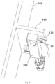
- Fig. 5 is an illustrative view of an electrical apparatus according to an exemplary embodiment of the present disclosure
- Fig. 6 is an illustrative view of a first electrical connection module 1 installed on a fixed member 310 of the electrical apparatus shown in Fig. 5
- Fig. 7 is an illustrative view of a second electrical connection module 2 installed on a moving member 320 of the electrical apparatus shown in Fig. 5 .
- the electrical connection assembly comprises a first electrical connection module 1 (see Figs. 1-2 ) and a second electrical connection module 2 (see Figs. 3-4 ).
- the first electrical connection module 1 is mounted on the fixed member 310.
- the second electrical connection module 2 is mounted on the moving member 320.
- Fig. 1 is an illustrative perspective view of a first electrical connection module 1 of an electrical connection assembly according to an exemplary embodiment of the present disclosure
- Fig. 2 is an illustrative view of the first electrical connection module 1 shown in Fig. 1 , wherein a first housing 100 of the first electrical connection module is removed.
- the first electrical connection module 1 has a first terminal 11 and a second terminal 12 adapted to electrically connect with a positive pole and a negative pole of a power supply (not shown), respectively.
- the first electrical connection module 1 further comprises a normally open switch 13.
- the normally open switch 13 is connected in series on an electrical connection line between the first terminal 11 and the positive pole of the power supply.
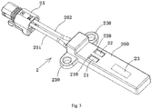
- Fig. 3 is an illustrative perspective view of a second electrical connection module 2 of an electrical connection assembly according to an exemplary embodiment of the present disclosure
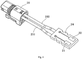
- Fig. 4 is an illustrative view of the second electrical connection module 2 shown in Fig. 3 , wherein a second housing 200 of the second electrical connection module 2 is removed.
- the second electrical connection module 2 has a first contact pad 21 and a second contact pad 22.
- the first contact pad 21 and a second contact pad 22 are adapted to electrically contact with the first terminal 11 and the second terminal 12, respectively.
- the second electrical connection module 2 further comprises a switch controller 23, and the switch controller 23 is configured to drive the normally open switch 13 to a closed state when the first contact pad 21 and the second contact pad 22 are moved to contact positions where the first contact pad 21 and the second contact pad 22 are in electrical contact with the first terminal 11 and the second terminal 12, respectively.
- the normally open switch 13 when the first contact pad 21 and the second contact pad 22 are moved to separation positions where the first contact pad 21 and the second contact pad 22 are separated from the first terminal 11 and the second terminal 12, respectively, the normally open switch 13 is automatically reset to its initial open state. In this way, when the movable member 320 is separated from the fixed member 310, the normally open switch 13 will disconnect the electrical connection line between the first terminal 11 and the power supply, thus enabling effective prevention of the risks of electric shock and short circuit.
- the normally open switch 13 may be a normally open reed
- the switch controller 23 may be a magnet.
- the magnet is moved to a position adjacent to the normally open reed, so that the normally open reed is switched from the open state to the closed state under the action of the magnetic field of the magnet.
- the magnet is moved to a position far away from the normally open reed, so that the normally open reed is automatically reset to its initial open state by its own elastic restoring force.
- normally open reed belongs to the prior art, for the sake of brevity, a detailed description thereof is omitted. However, it is noted that the normally open reed herein may be any suitable type of normally open reed in the prior art.
- the first electrical connection module 1 further comprises a first circuit board 14 on which the first terminal 11, the second terminal 12 and the normally open switch 13 are integrated.
- the first electrical connection module 1 further comprises a first housing 100 in which the first terminal 11, the second terminal 12, the normally open switch 13 and the first circuit board 14 are accommodated.
- a first opening 110 and a second opening 120 are formed in the first housing 100, and an elastic contact part 11a of the first terminal 11 and an elastic contact part 12a of the second terminal 12 are respectively exposed through the first opening 110 and the second opening 120, so as to electrically contact with the first contact pad 21 and the second contact pad 22, respectively.
- a first connecting ear 130 is formed on the first housing 100, and the first housing 100 is connected and fixed to the fixed member 310 by a first screwed connection part 131 passing through the first connecting ear 130, for example passing through a threaded opening of the first connecting ear.
- the first electrical connection module 1 further comprises a first connector 15.
- the first terminal 11 and the second terminal 12 are adapted to be electrically connected to the power supply by the first connector 15.
- the first connector 15 has a first connecting cable 151, one end of which is electrically connected to one end of the normally open switch 13 via a conductive trace on the first circuit board 14.
- the other end of the normally open switch 13 is electrically connected to a base end 11b of the first terminal 11 via a conductive trace on the first circuit board 14.
- the first connector 15 also has a second connecting cable 152, one end of which is electrically connected to a base end 12b of the second terminal 12 via a conductive trace on the first circuit board 14.
- the second electrical connection module 2 further comprises a second circuit board 24 on which the first contact pad 21 and the second contact pad 22 are integrated.
- the second electrical connection module 2 further comprises a second housing 200, in which the second circuit board 24, the first contact pad 21, the second contact pad 22 and the switch controller 23 are accommodated.
- the switch controller 23 is mounted on an inner wall of the second housing 200.
- the present disclosure is not limited to this; for example, the switch controller 23 may be mounted on the second circuit board 24.
- a first opening 210 and a second opening 220 are formed in the second housing 200, and the first contact pad 21 and the second contact pad 22 are respectively exposed through the first opening 210 and the second opening 220, so as to electrically contact with the first terminal 11 and the second terminal 12, respectively.
- a second connecting ear 230 is formed on the second housing 200, and the second housing 200 is connected and fixed to the moving member 320 by a second screwed connection part 231 passing through the second connecting ear 230, for example passing through a threaded opening of the second connecting ear.
- an electrical load (not shown) is provided on the moving member 320.
- the positive and negative ends of the electrical load are electrically connected to the first contact pad 21 and the second contact pad 22 of the second electric connection module 2, respectively.
- the second electrical connection module 2 further comprises a second connector 25.
- the first contact pad 21 and the second contact pad 22 are adapted to be electrically connected to the electrical load by the second connector 25.
- the second connector 25 has a first connecting cable 251, one end of which is electrically connected to the first contact pad 21 via a conductive trace on the second circuit board 24.
- the second connector 25 also has a second connecting cable 252, one end of which is electrically connected to the second contact pad 22 via a conductive trace on the second circuit board 24.
- an electrical apparatus comprises a fixed member 310, a moving member 320, the above-described electrical connection assembly shown in Figs. 1-4 , and an electrical load (not shown).
- the moving member 320 is movable relative to the fixed member 310.
- the first electrical connection module 1 of the electric connection assembly is installed on the fixed member 310, and the second electrical connection module 2 of the electrical connection assembly is installed on the moving member 320.
- the electrical load is provided on the moving member 320, a positive end and a negative end of the electrical load are electrically connected to the first contact pad 21 and the second contact pad 22 of the second electrical connection module 2, respectively.
- the electrical apparatus may be a refrigerator
- the moving member 320 may be a movable shelf for placing thereon articles in the refrigerator
- the fixed member 310 is a shelf bracket provided on an inner wall 300 of the refrigerator.
- the electrical apparatus is not limited to the refrigerator, for example, the electrical apparatus may be any other household appliances, such as, washing machine, air conditioner, etc.
- the switch controller 23 of the second electrical connection module 2 drives the normally open switch 13 of the first electrical connection module 1 to the closed state.
- the first contact pad 21 and the second contact pad 22 of the second electrical connection module 2 are moved to the separation positions where the first contact pad 21 and the second contact pad 22 are respectively separated from the first terminal 11 and the second terminal 12 of the electrical connection module 1, and the normally open switch 13 of the first electrical connection module 1 is automatically reset to its initial open state.
- the electrical load may be an illumination provided on the movable shelf of the refrigerator.
- the electrical connection assembly comprises a first electrical connection module 1.
- the first electrical connection module 1 is configured to be mounted on a fixed member 310 and has a first terminal 11 and a second terminal 12 configured to electrically connect with a positive pole and a negative pole of a power supply, respectively.
- the first terminal 11 and the second terminal 12 are adapted to electrically and respectively contact with a first contact pad 21 and a second contact pad 22 of a second electrical connection module 2.
- the first electrical connection module 1 further comprises a normally open switch 13, which is connected in series on an electrical connection line between the first terminal 11 and the positive pole of the power supply.
Landscapes
- Engineering & Computer Science (AREA)
- General Engineering & Computer Science (AREA)
- Chemical & Material Sciences (AREA)
- Combustion & Propulsion (AREA)
- Physics & Mathematics (AREA)
- Mechanical Engineering (AREA)
- Thermal Sciences (AREA)
- Microelectronics & Electronic Packaging (AREA)
- Details Of Connecting Devices For Male And Female Coupling (AREA)
- Coupling Device And Connection With Printed Circuit (AREA)
- Switch Cases, Indication, And Locking (AREA)
Applications Claiming Priority (1)
| Application Number | Priority Date | Filing Date | Title |
|---|---|---|---|
| CN201910619160.7A CN112290319A (zh) | 2019-07-10 | 2019-07-10 | 电连接组件和电器设备 |
Publications (2)
| Publication Number | Publication Date |
|---|---|
| EP3764484A2 true EP3764484A2 (de) | 2021-01-13 |
| EP3764484A3 EP3764484A3 (de) | 2021-06-02 |
Family
ID=71111270
Family Applications (1)
| Application Number | Title | Priority Date | Filing Date |
|---|---|---|---|
| EP20180982.9A Pending EP3764484A3 (de) | 2019-07-10 | 2020-06-19 | Elektrische verbindungsanordnung und elektrische vorrichtung |
Country Status (4)
| Country | Link |
|---|---|
| US (1) | US12149035B2 (de) |
| EP (1) | EP3764484A3 (de) |
| KR (1) | KR20210007878A (de) |
| CN (1) | CN112290319A (de) |
Family Cites Families (21)
| Publication number | Priority date | Publication date | Assignee | Title |
|---|---|---|---|---|
| BE880374A (fr) * | 1979-11-30 | 1980-05-30 | S P R L Amplikart P V B A | Connecteurs electriques munis d'aimants |
| NL8900092A (nl) * | 1989-01-16 | 1990-08-16 | Du Pont Nederland | Connector met een schakelinrichting. |
| JPH0812032B2 (ja) * | 1990-09-19 | 1996-02-07 | 三洋電機株式会社 | 冷蔵庫 |
| ATE370534T1 (de) * | 2003-03-21 | 2007-09-15 | Campagnolo Srl | Einheiten zur steuerung der betriebsfunktionen eines fahrrads |
| DE102006057083A1 (de) * | 2005-12-05 | 2007-06-28 | Lg Electronics Inc. | Beleuchtungsvorrichtung für einen Kühlschrank |
| KR101286902B1 (ko) * | 2006-09-06 | 2013-07-16 | 엘지전자 주식회사 | 냉장고의 조명장치 및 조명방법 |
| US9544967B2 (en) * | 2011-04-15 | 2017-01-10 | Wireless Environment, Llc | Lighting device capable of maintaining light intensity in demand response applications |
| CN202474456U (zh) * | 2011-12-12 | 2012-10-03 | 巫志丰 | 磁控防触电插座 |
| EP2865051B1 (de) * | 2012-06-21 | 2019-01-09 | Ideal Industries, Inc. | Elektrischer verbinder zur verwendung mit bestückten leiterplatten |
| FR3010245B1 (fr) * | 2013-08-28 | 2016-10-21 | Oreal | Assemblage electrique a connexion etanche |
| CN203719313U (zh) * | 2013-12-17 | 2014-07-16 | 合肥美的电冰箱有限公司 | 冰箱发光搁架组件和具有其的冰箱 |
| KR102388089B1 (ko) * | 2014-09-04 | 2022-04-19 | 삼성전자주식회사 | 냉장고 및 그 제어 방법 |
| CN106152655B (zh) * | 2015-03-30 | 2019-11-29 | 松下电器研究开发(苏州)有限公司 | 冰箱 |
| KR102573836B1 (ko) * | 2015-04-27 | 2023-09-05 | 엘지전자 주식회사 | 냉장고 |
| EP3169958B1 (de) * | 2015-04-27 | 2019-07-31 | LG Electronics Inc. | Kühlschrank mit tür und verfahren zur herstellung der kühlschranktür |
| EP3889528B1 (de) * | 2015-11-04 | 2023-01-04 | LG Electronics Inc. | Kühlschrank |
| KR102358755B1 (ko) * | 2015-11-04 | 2022-02-07 | 엘지전자 주식회사 | 냉장고 |
| KR102314319B1 (ko) * | 2016-01-04 | 2021-10-20 | 엘지전자 주식회사 | 냉장고 |
| US11104502B2 (en) * | 2016-03-01 | 2021-08-31 | Jeffrey S. Melcher | Multi-function compact appliance and methods for a food or item in a container with a container storage technology |
| CN107300286B (zh) * | 2017-06-29 | 2019-12-06 | 青岛海尔电冰箱有限公司 | 用于冰箱的照明装置 |
| CN111238115B (zh) * | 2018-11-29 | 2022-09-09 | 博西华电器(江苏)有限公司 | 冰箱 |
-
2019
- 2019-07-10 CN CN201910619160.7A patent/CN112290319A/zh active Pending
-
2020
- 2020-06-19 EP EP20180982.9A patent/EP3764484A3/de active Pending
- 2020-07-06 US US16/921,130 patent/US12149035B2/en active Active
- 2020-07-08 KR KR1020200084027A patent/KR20210007878A/ko not_active Ceased
Also Published As
| Publication number | Publication date |
|---|---|
| KR20210007878A (ko) | 2021-01-20 |
| US12149035B2 (en) | 2024-11-19 |
| US20210013686A1 (en) | 2021-01-14 |
| CN112290319A (zh) | 2021-01-29 |
| EP3764484A3 (de) | 2021-06-02 |
Similar Documents
| Publication | Publication Date | Title |
|---|---|---|
| CN101800385B (zh) | 磁力电连接器 | |
| US9768562B2 (en) | Modified electrical devices | |
| CN104380538B (zh) | 安全插座及其应用 | |
| CN201608374U (zh) | 磁力电连接器 | |
| EP3162420A1 (de) | Modularer baustein und elektronisches bausteinsystem | |
| CN205724065U (zh) | 一种具有防开路功能的连接器 | |
| CN105448560B (zh) | 智能开关装置 | |
| CN111244703B (zh) | 一种防触电插座 | |
| US10686284B2 (en) | Power over ethernet connection with power control | |
| EP3764484A2 (de) | Elektrische verbindungsanordnung und elektrische vorrichtung | |
| CN201994480U (zh) | 一种多功能安全插座装置 | |
| EP3731347B1 (de) | Elektrische vorrichtung | |
| CN217589679U (zh) | Led显示装置的插接结构及led显示装置 | |
| CN210517204U (zh) | 安全插头 | |
| CN217589477U (zh) | Led显示装置的对插装置及led显示装置 | |
| EP3886271B1 (de) | Leckageschutzvorrichtung | |
| CN217405745U (zh) | 一种电源插座 | |
| CN114883874A (zh) | Led显示装置的插接结构及led显示装置 | |
| CN204156163U (zh) | 一种电子接插件 | |
| CN207896036U (zh) | 一种触头保护式继电器 | |
| CN106450899A (zh) | 一种多控结构的安全插座 | |
| CN108493721B (zh) | 三极通断漏电保护插头 | |
| CN206742599U (zh) | 插头及插头组件 | |
| CN206250435U (zh) | 一种多控结构的安全插座 | |
| CN110911890B (zh) | 一种吸附式便于使用的插座插头 |
Legal Events
| Date | Code | Title | Description |
|---|---|---|---|
| PUAI | Public reference made under article 153(3) epc to a published international application that has entered the european phase |
Free format text: ORIGINAL CODE: 0009012 |
|
| STAA | Information on the status of an ep patent application or granted ep patent |
Free format text: STATUS: REQUEST FOR EXAMINATION WAS MADE |
|
| 17P | Request for examination filed |
Effective date: 20200619 |
|
| AK | Designated contracting states |
Kind code of ref document: A2 Designated state(s): AL AT BE BG CH CY CZ DE DK EE ES FI FR GB GR HR HU IE IS IT LI LT LU LV MC MK MT NL NO PL PT RO RS SE SI SK SM TR |
|
| AX | Request for extension of the european patent |
Extension state: BA ME |
|
| PUAL | Search report despatched |
Free format text: ORIGINAL CODE: 0009013 |
|
| AK | Designated contracting states |
Kind code of ref document: A3 Designated state(s): AL AT BE BG CH CY CZ DE DK EE ES FI FR GB GR HR HU IE IS IT LI LT LU LV MC MK MT NL NO PL PT RO RS SE SI SK SM TR |
|
| RIC1 | Information provided on ipc code assigned before grant |
Ipc: H01R 13/66 20060101AFI20210427BHEP Ipc: H01R 13/703 20060101ALI20210427BHEP Ipc: H01H 3/16 20060101ALI20210427BHEP Ipc: H01R 12/70 20110101ALN20210427BHEP Ipc: H01R 12/71 20110101ALN20210427BHEP Ipc: F25D 25/02 20060101ALN20210427BHEP Ipc: F21W 131/305 20060101ALN20210427BHEP |
|
| RBV | Designated contracting states (corrected) |
Designated state(s): AL AT BE BG CH CY CZ DE DK EE ES FI FR GB GR HR HU IE IS IT LI LT LU LV MC MK MT NL NO PL PT RO RS SE SI SK SM TR |