EP3764157B1 - Apparatus and method for stabilization and vibration reduction - Google Patents
Apparatus and method for stabilization and vibration reduction Download PDFInfo
- Publication number
- EP3764157B1 EP3764157B1 EP20183646.7A EP20183646A EP3764157B1 EP 3764157 B1 EP3764157 B1 EP 3764157B1 EP 20183646 A EP20183646 A EP 20183646A EP 3764157 B1 EP3764157 B1 EP 3764157B1
- Authority
- EP
- European Patent Office
- Prior art keywords
- optical unit
- frame assembly
- imaging device
- rotational axis
- axis
- Prior art date
- Legal status (The legal status is an assumption and is not a legal conclusion. Google has not performed a legal analysis and makes no representation as to the accuracy of the status listed.)
- Active
Links
Images






Classifications
-
- B—PERFORMING OPERATIONS; TRANSPORTING
- B64—AIRCRAFT; AVIATION; COSMONAUTICS
- B64U—UNMANNED AERIAL VEHICLES [UAV]; EQUIPMENT THEREFOR
- B64U10/00—Type of UAV
- B64U10/10—Rotorcrafts
- B64U10/13—Flying platforms
- B64U10/14—Flying platforms with four distinct rotor axes, e.g. quadcopters
-
- B—PERFORMING OPERATIONS; TRANSPORTING
- B64—AIRCRAFT; AVIATION; COSMONAUTICS
- B64U—UNMANNED AERIAL VEHICLES [UAV]; EQUIPMENT THEREFOR
- B64U20/00—Constructional aspects of UAVs
- B64U20/80—Arrangement of on-board electronics, e.g. avionics systems or wiring
- B64U20/87—Mounting of imaging devices, e.g. mounting of gimbals
-
- G—PHYSICS
- G03—PHOTOGRAPHY; CINEMATOGRAPHY; ANALOGOUS TECHNIQUES USING WAVES OTHER THAN OPTICAL WAVES; ELECTROGRAPHY; HOLOGRAPHY
- G03B—APPARATUS OR ARRANGEMENTS FOR TAKING PHOTOGRAPHS OR FOR PROJECTING OR VIEWING THEM; APPARATUS OR ARRANGEMENTS EMPLOYING ANALOGOUS TECHNIQUES USING WAVES OTHER THAN OPTICAL WAVES; ACCESSORIES THEREFOR
- G03B15/00—Special procedures for taking photographs; Apparatus therefor
- G03B15/006—Apparatus mounted on flying objects
-
- H—ELECTRICITY
- H04—ELECTRIC COMMUNICATION TECHNIQUE
- H04N—PICTORIAL COMMUNICATION, e.g. TELEVISION
- H04N23/00—Cameras or camera modules comprising electronic image sensors; Control thereof
- H04N23/50—Constructional details
- H04N23/51—Housings
-
- H—ELECTRICITY
- H04—ELECTRIC COMMUNICATION TECHNIQUE
- H04N—PICTORIAL COMMUNICATION, e.g. TELEVISION
- H04N23/00—Cameras or camera modules comprising electronic image sensors; Control thereof
- H04N23/50—Constructional details
- H04N23/54—Mounting of pick-up tubes, electronic image sensors, deviation or focusing coils
-
- H—ELECTRICITY
- H04—ELECTRIC COMMUNICATION TECHNIQUE
- H04N—PICTORIAL COMMUNICATION, e.g. TELEVISION
- H04N23/00—Cameras or camera modules comprising electronic image sensors; Control thereof
- H04N23/50—Constructional details
- H04N23/55—Optical parts specially adapted for electronic image sensors; Mounting thereof
-
- H—ELECTRICITY
- H04—ELECTRIC COMMUNICATION TECHNIQUE
- H04N—PICTORIAL COMMUNICATION, e.g. TELEVISION
- H04N23/00—Cameras or camera modules comprising electronic image sensors; Control thereof
- H04N23/60—Control of cameras or camera modules
- H04N23/63—Control of cameras or camera modules by using electronic viewfinders
-
- H—ELECTRICITY
- H04—ELECTRIC COMMUNICATION TECHNIQUE
- H04N—PICTORIAL COMMUNICATION, e.g. TELEVISION
- H04N23/00—Cameras or camera modules comprising electronic image sensors; Control thereof
- H04N23/60—Control of cameras or camera modules
- H04N23/68—Control of cameras or camera modules for stable pick-up of the scene, e.g. compensating for camera body vibrations
- H04N23/681—Motion detection
- H04N23/6812—Motion detection based on additional sensors, e.g. acceleration sensors
-
- H—ELECTRICITY
- H04—ELECTRIC COMMUNICATION TECHNIQUE
- H04N—PICTORIAL COMMUNICATION, e.g. TELEVISION
- H04N23/00—Cameras or camera modules comprising electronic image sensors; Control thereof
- H04N23/60—Control of cameras or camera modules
- H04N23/68—Control of cameras or camera modules for stable pick-up of the scene, e.g. compensating for camera body vibrations
- H04N23/682—Vibration or motion blur correction
- H04N23/685—Vibration or motion blur correction performed by mechanical compensation
-
- H—ELECTRICITY
- H04—ELECTRIC COMMUNICATION TECHNIQUE
- H04N—PICTORIAL COMMUNICATION, e.g. TELEVISION
- H04N23/00—Cameras or camera modules comprising electronic image sensors; Control thereof
- H04N23/60—Control of cameras or camera modules
- H04N23/68—Control of cameras or camera modules for stable pick-up of the scene, e.g. compensating for camera body vibrations
- H04N23/682—Vibration or motion blur correction
- H04N23/685—Vibration or motion blur correction performed by mechanical compensation
- H04N23/687—Vibration or motion blur correction performed by mechanical compensation by shifting the lens or sensor position
-
- H—ELECTRICITY
- H04—ELECTRIC COMMUNICATION TECHNIQUE
- H04N—PICTORIAL COMMUNICATION, e.g. TELEVISION
- H04N23/00—Cameras or camera modules comprising electronic image sensors; Control thereof
- H04N23/60—Control of cameras or camera modules
- H04N23/695—Control of camera direction for changing a field of view, e.g. pan, tilt or based on tracking of objects
-
- H—ELECTRICITY
- H04—ELECTRIC COMMUNICATION TECHNIQUE
- H04N—PICTORIAL COMMUNICATION, e.g. TELEVISION
- H04N25/00—Circuitry of solid-state image sensors [SSIS]; Control thereof
- H04N25/40—Extracting pixel data from image sensors by controlling scanning circuits, e.g. by modifying the number of pixels sampled or to be sampled
- H04N25/41—Extracting pixel data from a plurality of image sensors simultaneously picking up an image, e.g. for increasing the field of view by combining the outputs of a plurality of sensors
-
- H—ELECTRICITY
- H04—ELECTRIC COMMUNICATION TECHNIQUE
- H04N—PICTORIAL COMMUNICATION, e.g. TELEVISION
- H04N7/00—Television systems
- H04N7/18—Closed-circuit television [CCTV] systems, i.e. systems in which the video signal is not broadcast
- H04N7/183—Closed-circuit television [CCTV] systems, i.e. systems in which the video signal is not broadcast for receiving images from a single remote source
- H04N7/185—Closed-circuit television [CCTV] systems, i.e. systems in which the video signal is not broadcast for receiving images from a single remote source from a mobile camera, e.g. for remote control
-
- B—PERFORMING OPERATIONS; TRANSPORTING
- B64—AIRCRAFT; AVIATION; COSMONAUTICS
- B64U—UNMANNED AERIAL VEHICLES [UAV]; EQUIPMENT THEREFOR
- B64U2101/00—UAVs specially adapted for particular uses or applications
- B64U2101/30—UAVs specially adapted for particular uses or applications for imaging, photography or videography
Definitions
- Lens stabilization and sensor stabilization are now widely applied in many consumer digital cameras.
- the general principle of lens stabilization is to eliminate the shake on the lens by controlling horizontal displacement or rotation of a certain lens or some lenses; and sensor stabilization is intended to offset the vibration by enabling a photosensitive sensor to translate or rotate.
- Lens stabilization and sensor stabilization are both implemented within the shooting equipment, requiring minimal volume.
- vibration with large amplitude or at high frequency is still difficult to eliminate completely, particularly when carrying the shooting equipment or mounting video equipment on a moving vehicle.
- US 2004/ 183907 A1 describes an optical block assemblies having single or multistage folded light path lens assemblies that may be implemented to allow an optical block assembly to occupy significantly less space and/or present reduced rotational inertia to an electrical articulating mechanism.
- An optical assembly may be so configured for closed circuit television applications or in any other suitable video imaging application including, but not limited to, applications involving non-articulated or articulated cameras such as normal filming (e.g., motion picture film cameras or studio television cameras), camcorders, military targeting or imaging devices, etc.
- US 2012/0316685 A1 describes a gimbal system for mounting a gimbal apparatus to a support platform with a mount assembly.
- the mount assembly may include first and second bar assemblies that are rotationally coupled to each other by a pair of gears.
- US 2005/185089 A1 describes a remote camera head that has a tilt frame attachable to a pan frame at multiple positions.
- a roll frame is attachable to the tilt frame at multiple positions.
- the camera head can be expanded or reduced in size.
- the present invention relates to an apparatus according to independent claim 1, and to an aerial vehicle and to a method according to the other independent claims.
- Apparatus and methods have been developed to reduce the effects of vibration and allow for the size reduction of stabilization equipment for photography and videography, by separating the components of the imaging device, reducing the relative mass of all components involved, and focusing the majority of the stabilization efforts near the optics components of the imaging device.
- a positional sensor shall mean: motion sensors (accelerometers) and rotation sensors (gyroscopes) or other inertial sensors to continuously calculate via dead reckoning the position, orientation, and velocity (direction and speed of movement) of a moving object without the need for external references"; e.g.: "state information”.
- Positional sensors shall also include sensors that use external references such as compasses, and GPS (global positioning system) sensors, and the like.
- the apparatus incorporates controllers for generating one or more motor signals for driving the movement of the frame assembly of the apparatus, based on the state information generated by the sensors.
- the imaging device comprises an optical unit and a non-optical unit.
- the apparatus comprises a frame assembly rotatably coupled to the optical unit of the imaging device, wherein said frame is configured to permit the optical unit to rotate about at least a first rotational axis and a second rotational axis, the optical unit comprising at least a lens and a photosensor.
- Said apparatus comprising a frame assembly having a volume that is less than that of a frame assembly required to support the entire imaging device having the optical unit and the non-optical unit.
- said frame assembly will have a volume that is no more than one half of that of a frame assembly required to support the entire imaging device.
- Said apparatus also having a motor assembly wherein the motor assembly consumes a minimum amount of energy that is less than that required to drive a frame assembly supporting the entire imaging device.
- said motor assembly will consume no more than one half of the amount of energy than that of a motor assembly required to drive a frame assembly supporting the entire imaging device.
- Said apparatus can be configured to be coupled to a moving vehicle, an aerial vehicle, or can be handheld.
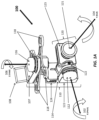
- an exemplary apparatus 100 for stabilizing an imaging device 115, (108 + 120) comprising an optical unit 120 and a non-optical unit 108 said apparatus comprising: a frame assembly 110 rotatably coupled to the optical unit 120 of the imaging device, without supporting the entire imaging device as a whole 115, wherein the frame assembly 110 configured to permit the optical unit 120 to rotate about at least a first rotational axis 102 and a second rotational axis 104, the optical unit 120 comprising at least a lens 121 and a photosensor 123 that is optically coupled to the lens; and a motor assembly 112, 114 coupled to the frame assembly 110, the motor assembly configured to directly drive the frame assembly so as to permit the optical unit to rotate about at least the first rotational axis 102 or the second rotational axis 104.
- the non-optical unit is coupled to the frame assembly on a base 107, which can be on a completely different part of the frame, or even a
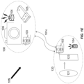
- FIG.1B illustrates one possible configuration of an imaging device 115, wherein the optical unit 120 and the non-optical unit 108 are physically separated, but coupled by optical cabling 101 or wiring, and electrically coupled at each end 101a, and 101b.
- the non-optical unit is comprises a housing 109, a battery 104 and storage media 105.
- the optical unit 120 comprises a lens 121, and a photosensor 123.
- the non-optical unit 108 of the imaging device is not mechanically coupled to the apparatus. It is understandable that once one realizes that the components of the imaging device can be physically separated, it is no longer necessary for both components to be physically located on the same apparatus.
- the optical unit 120 may be located on the apparatus, while the non-optical unit 120 is located somewhere else, preferably nearby, but not necessarily.
- the optical unit and the non-optical unit are electrically coupled ( FIG. 1B ). This may typically be accomplished by optical cabling or electrical wiring 101.
- the optical unit and the non-optical unit are movable relative to each other. As shown in FIG. 1 and further illustrated in FIG.
- the optical unit and non-optical unit when the optical unit and non-optical unit are physically separated, and physically located on separate mounting bases, and/or separate axes of a multi-axis apparatus, such as described herein, the optical unit and non-optical unit can be configured to each other, by design.
- the non-optical unit of the imaging device is not mechanically coupled to the optical unit of the imaging device, as illustrated in FIGS. 1C - 1E by other mean including but not limited to wireless 101c communication between the optical unit and the non-optical unit.
- wireless means of communication include electromagnetic telecommunications, (i.e.: radio), and point-to-point, or point-to-multi-point wireless networking, or alternately, light (e.g.: infrared), magnetic, or electric fields.
- the optical unit 120 of the imaging device 115 further comprises at least one of a filter (not shown), positional sensor (not shown), storage medium 105, battery 104, zooming motor (not shown), circuitry 103, power supply (alternately 104), processor (not shown), or housing (not shown).
- a filter not shown
- positional sensor not shown
- storage medium 105 not shown
- battery 104 zooming motor
- circuitry 103 power supply
- processor not shown
- housing not shown
- the optical unit of the imaging device further comprises a weight adapted to provide stability for the optical unit.
- a weight adapted to provide stability for the optical unit.
- the weight may comprise a battery 104.
- the non-optical unit comprises storage medium 105.
- the non-optical 108 unit does not include a lens 121, or a photosensor 123, as illustrated in FIGS. 1B - 1E .
- the non-optical unit of the imaging device comprises at least one of a positional sensor (not shown), battery 104, motors (not shown), circuitry 103, power supply, processor (not shown), or housing 109.
- At least one of the first rotational axis 102 and the second rotational axis 104 corresponds to a pitch, roll or yaw axis of the optical unit.
- the frame assembly is further configured to permit the optical unit to rotate about a third rotational axis 106.
- the third rotational axis corresponds to at least one of a pitch, roll, or yaw axis of the optical unit.
- axes of rotation can be randomly substituted, as appropriate, to meet the needs of a given application; meaning X-axis (pitch) rotation can be substituted with Y-axis (roll) rotation, or Z-axis (yaw) rotation can be substituted with X-axis (pitch) rotation, etc.
- the apparatus further comprises one or more positional sensors 122, wherein at least one of the one or more positional sensors is configured to detect state information associated with the optical unit 120.
- the apparatus further comprises a controller for generating one or more motor signals 124 based on the state information associated with the optical unit.
- the state information comprises translational or rotational movement information or positional information.
- At least one of the positional sensors is configured to detect state information associated with the non-optical unit. This is useful for orienting the image generated by the imaging device in space, e.g., especially when the non-optical unit is mounted on a base (e.g.: 107) that may represent the horizontal or vertical axis of a carrier device.
- a base e.g.: 107
- At least one of the one or more positional sensors is configured to measure movement associated with at least a pitch, roll, or yaw axis of the optical unit.
- at least one of the one or more positional sensors comprises an inertial sensor.
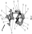
- the rotational (pitch) axis X 202 of the first frame member mounting base 227 is orthogonally disposed relative to the rotational (roll) axis Y 204, for example, to allow the motors to easily and timely adjust the rotation of the frame assembly.
- the rotational axes are not orthogonally disposed to each other such as in FIG.3 .
- the rotational (roll) axis X 404 is orthogonally disposed relative to the rotational (yaw) axis Y 406, for example, to allow the motors to easily and timely adjust the rotation of the frame assembly.
- the rotational axes are not orthogonally disposed to each other such as in FIG.3 .
- the center of gravity of the first frame member mounting base 308 and the payload device 309 as a whole is preferably located on the rotational (pitch) axis X 302 of the first frame member, as illustrated in FIG. 3 .
- the pitch axis intersects with the payload device 309. It is appreciated that when the center of gravity of the first frame member and the payload device 309 is positioned on the rotational axis X 302 of the first frame member, the rotation of the first frame member does not generate any torque. In other words, the first frame member is not likely to have any swing movement caused by the torque. Thus, the stability of the payload device is enhanced during rotation.
- the first frame member and the payload device 309 is also in a dynamically balanced state.
- the center of gravity of the first frame member, the second frame member and the payload device 309 as a whole is located on the rotational axis Y 304 of the second frame member.
- the rotational Y (roll) axis 304 intersects with the payload device 309.
- the frame assembly can provide near limitless ranges of motion for axes 1, 2, or 3, allowing for rotational swings of X, Y or Z axes, individually or together, in ranges from 0 - 360 degrees or more, allowing the payload device 309 to circumferentially rotate (e.g., up to 360 degrees, 720 degrees, or more, in any axis), for example, in order to perform panoramic photography.
- the apparatus can be configured to be coupled to a movable object.
- the fixing points 118, 218, 318, 418 may be used to mount the mointing base 201 to or to facilitate the carrying of the stabilizing platform by a carrier, such as an aerial vehicle, motor vehicle, ship, robot, human, or any other movable object.
- the mointing base 201 may be handheld by a human, for example, to perform dynamic videography or photography.
- a moveable object may be anything that can move relative to the earth.
- moveable objects can be a wheeled-vehicle; a tracked-vehicle; a sliding or sledded vehicle; an aircraft; a hovercraft; a watercraft; or a spacecraft.
- a moving object can be a human being; a mammal; an aquatic animal; an amphibious animal; a reptile; a bird; or an invertebrate animal.
- a moving object can be relatively fixed, but still capable of movement, such as a tree, pole, or even a building that may be subject to swaying or vibration due to wind or even earthquakes.
- the apparatus is configured to reduce relatively more movement experienced by the optical unit caused by the movable object than the amount of movement experienced by the non-optical unit.
- This movement can include but limit one of vibration, shock, sway, tremor, shaking, or jerking movement.
- the apparatus for stabilizing an imaging device comprising an optical unit and a non-optical unit is configured to be handheld.
- Such apparatus can produce a more stable platform for vibration-resistant or even vibration-free imagery by, e.g., isolating the optical unit of an imaging device. Since a large proportion of the overall weight of an imaging device is associated with components and sub-components that are not directly associated with the lens and photosensor, the apparatus is designed to provide better vibration dampening and higher response rates to the smaller and lighter components of the optical unit alone.
- the frame assembly comprises a first stage connected to and supporting the optical unit, a second stage movable relative to the first stage, and the optical unit about the first rotational axis.
- the frame assembly can further comprise a third stage movable relative to the second stage about the second rotational axis.
- an apparatus for stabilizing at least a portion of an imaging device that comprises an optical unit and a non-optical unit
- said apparatus comprising a frame assembly having a volume that is less than that of a frame assembly required to support the entire imaging device having the optical unit and the non-optical unit as potentially illustrated in FIGS 4 and 5B
- the frame assembly is configured to support the optical unit 120 of the imaging device, wherein the frame assembly is configured to permit rotation of the optical unit about at least a first rotational axis 102 and a second rotational axis 104
- the optical unit comprises at least a lens 121 and a photosensor 123 that is optically coupled to the lens
- the motor assembly 112 or 114 (not shown) is configured to drive the frame assembly 110 so as to permit rotation of the optical unit 120 about at least the first rotational axis 102 or the second rotational axis 104.
- a frame assembly has a volume that is preferably one half or less than that of a frame assembly required to support the entire imaging device.
- miniaturized components of the optical unit, described herein, and illustrated in FIG. 1 have the following proportions, wherein a 1/2.33" photosensor having an imaging area of 6.13 x 4.6 mm, weighs 0.6g.
- the overall dimensions would be approximately 2.5cm x 1.8cm x 3cm.
- the non-optical unit of an imaging system designed to work with this optical unit would have the outer dimension volumes of 77mm x 67mm x 80mm, and have a total weight of 80g (excluding the optical component).
- the motor along each axis of a 3-axis frame assembly has a rated power of only about 2w.
- the invention described herein compares very favorably to other successful "compact" imaging systems having a 1/2.33" photosensor such as one by GoPro ® , wherein the dimensions are 58.4 x 38.1 x 20.3 mm and the weights are approximately 75g.
- For stabilizing the whole GoPro camera currently existing 2-axis platforms weigh 200g (excluding the camera), with an outer dimensional volume of 93mm x 85mm x 100mm.
- the much larger motors required to drive the larger frames require 5w power levels for each motor along each axis.
- the volume of the frame assembly required for stabilization is less than that is required to support the entire imaging device.
- the volume of the frame assembly is reduced by 10%, 20%, 30%, 40%, 50%, 60%, 70%, 100% or more as compared to the volume of a frame assembly for supporting the entire imaging device.
- the volume of the frame assembly is merely 1 ⁇ 2, 1/3, 1 ⁇ 4, 1/5 or less of that is required for supporting the entire imaging device having the optical and non-optical units as a whole.
- the minimum amount of the energy required by a subject motor to drive the subject frame assembly is less than that is required to drive a frame assembly supporting the entire imaging device.
- the motor consumes a minimum amount of energy that is 90%, 80%, 70%, 60%, 50%, 40%, 30%, 20%, 10% or even less than that which is required for a motor driving a frame assembly supporting the whole imaging device (e.g., with optical and the non-optical units as an integral piece).
- the minimum amount of energy required by the subject motor is less than 5W, 4W, 3W, 2W, 1W power to drive along an axis of a frame assembly.
- the non-optical unit of the imaging device 115 is not mechanically coupled to the apparatus.
- the optical unit and the non-optical unit are electrically coupled.
- the optical unit and the non-optical unit are movable relative to each other. As shown in FIG. 1 , when the optical unit and non-optical unit are physically separated, and physically located on separate mounting bases, and/or separate axes of a multi-axis apparatus, such as described herein, the optical unit and non-optical unit will move relative to each other, by design.
- the non-optical unit 108 of the imaging device 115 is not mechanically coupled to the optical unit of the imaging device, as illustrated in in FIGS. 1B - 1E .
- the apparatus described herein can employ a means of wireless communication 101c between the optical unit and the non-optical unit.
- wireless means of communication include electromagnetic telecommunications, (i.e.: radio), and point-to-point, or point-to-multi-point wireless networking, or alternately, light (e.g.: infrared), magnetic, or electric fields.
- At least one of the first rotational axis and the second rotational axis corresponds to a pitch, roll or yaw axis of the optical unit.
- the frame assembly is further configured to permit the optical unit to rotate about a third rotational axis.
- the third rotational axis corresponds to at least one of a pitch, roll, or yaw axis of the optical unit.
- the apparatus further comprises one or more positional sensors, wherein at least one of the one or more positional sensors is configured to detect state information associated with the optical unit.
- the apparatus further comprises a controller for generating one or more motor signals based on the state information associated with the optical unit.
- the state information comprises translational or rotational movement information or positional information.
- At least one of the positional sensors is configured to detect state information associated with the non-optical unit.
- At least one of the one or more positional sensors is configured to measure movement associated with at least a pitch, roll, or yaw axis of the optical unit.
- at least one of the one or more positional sensors comprises an inertial sensor.
- the apparatus is configured to be coupled to a movable object.
- the apparatus is configured to reduce relatively more movement experienced by the optical unit caused by the movable object than the amount of movement experienced by the non-optical unit.
- the apparatus for stabilizing at least a portion of an imaging device comprising an optical unit and a non-optical unit is configured to be handheld.
- the frame assembly comprises a first stage connected to and supporting the optical unit, and a second stage movable relative to the first stage and the optical unit about the first rotational axis.
- the frame assembly comprises a third stage movable relative to the second stage about the second rotational axis.
- an apparatus for stabilizing at least a portion of an imaging device that comprises an optical unit and a non-optical unit
- said apparatus comprising: a frame assembly supporting the optical unit of the imaging device, wherein the frame assembly is configured to permit rotation of the optical unit about at least a first rotational axis and a second rotational axis, and wherein the optical unit comprises at least a lens and a photosensor that is optically coupled to the lens; and a motor assembly operably connected to the frame assembly, wherein the motor assembly is configured to drive the frame assembly so as to permit rotation of the optical unit about at least the first rotational axis or the second rotational axis, and wherein the motor assembly consumes a minimum amount of energy that is less than that required to drive a frame assembly supporting the entire imaging device.
- the motor assembly will preferably consume no more than one half of the amount of energy than that of a motor assembly required to drive a frame assembly supporting the entire imaging device.
- the motor along each axis of a 3-axis frame assembly of the subject invention has a rated power of only about 2w.
- An alternative illustrative embodiment for a 3-axis frame is illustrated in FIG. 2 , (no imaging device shown).
- the non-optical unit of the imaging device is not mechanically coupled to the apparatus. In some embodiments the optical unit and the non-optical unit are electrically coupled. In some embodiments the optical unit and the non-optical unit are movable relative to each other.
- the non-optical unit of the imaging device is not mechanically coupled to the optical unit of the imaging device.
- the apparatus described herein can employ a means of wireless communication between the optical unit and the non-optical unit.
- wireless means of communication include electromagnetic telecommunications, (i.e.: radio), and point-to-point, or point-to-multi-point wireless networking, or alternately, light (e.g.: infrared), magnetic, or electric fields.
- the optical unit of the imaging device further comprises at least one of a filter, positional sensor, storage medium, battery, zooming motor, circuitry, power supply, processor, or housing.
- the optical unit of the imaging device further comprises a weight adapted to provide stability for the optical unit.
- the weight comprises a battery.
- the non-optical unit comprises a storage medium.
- the non-optical unit does not include a lens or a photosensor.
- the non-optical unit of the imaging device comprises at least one of a positional sensor, battery, motors, circuitry, power supply, processor, or housing.
- At least one of the first rotational axis and the second rotational axis corresponds to a pitch, roll or yaw axis of the optical unit.
- the frame assembly is further configured to permit the optical unit to rotate about a third rotational axis.
- the third rotational axis corresponds to at least one of a pitch, roll, or yaw axis of the optical unit.
- the apparatus further comprises one or more positional sensors, wherein at least one of the one or more positional sensors is configured to detect state information associated with the optical unit.
- the apparatus further comprises a controller for generating one or more motor signals based on the state information associated with the optical unit.
- the state information comprises translational or rotational movement information or positional information.
- At least one of the positional sensors is configured to detect state information associated with the non-optical unit.
- At least one of the one or more positional sensors is configured to measure movement associated with at least a pitch, roll, or yaw axis of the optical unit.
- at least one of the one or more positional sensors comprises an inertial sensor.
- the apparatus is configured to be coupled to a movable object.
- the apparatus is configured to reduce relatively more movement experienced by the optical unit caused by the movable object than the amount of movement experienced by the non-optical unit.
- the apparatus for stabilizing at least a portion of an imaging device comprising an optical unit and a non-optical unit is configured to be handheld.
- the frame assembly comprises a first stage connected to and supporting the optical unit, and a second stage movable relative to the first stage and the optical unit about the first rotational axis.
- the frame assembly comprises a third stage movable relative to the second stage about the second rotational axis.
- said energy is less than the amount of energy required to drive the frame assembly when the entire imaging device apparatus as a whole is supported by the frame assembly.
- an apparatus for stabilizing at least a portion of an imaging device that comprises an optical unit and a non-optical unit
- the motor assembly consumes a minimum amount of energy that is less than that required to drive a frame assembly supporting the entire imaging device
- said energy is less than the amount of energy required to drive the frame assembly when the entire imaging device apparatus as a whole is supported by the frame assembly.
- At least one embodiment of the apparatus comprises a frame assembly configured to support an entire imaging device, wherein the components have been separated and are placed at different locations on the frame.
- the non-optical unit is placed on the base 107, on the Z-axis frame, whereas the optical unit is connected to the X-axis frame.
- the mass of the non-optical component can be completely isolated from the optical unit, thus allowing for a mixture of frame assembly components, with larger motors and frame base on the Z-plane, and the use of smaller configuration frame components below the Z-plane and subsequently use motors that consume less energy to drive the frame controlling only the optical unit movements.
- This example is only meant as one illustrative example of the numerous possible configurations and sub-configurations which are now possible.
- an imaging device comprising an optical unit 309 which comprises at least a lens and a photosensor that is optically coupled to the lens; and a non-optical unit that is electrically coupled to the optical unit (not-shown), wherein the optical unit is movable relative to the non-optical unit via actuation of a frame assembly 300 coupled to said optical unit, as previously illustrated in FIG. 1 .
- the non-optical unit is not mechanically coupled to the frame assembly.
- a representative three-axis frame assembly 300 is illustrated with an optical unit 309 coupled to the X-axis 302 of the frame in a carrier bracket 308, however, the non-optical unit is remotely located somewhere off the frame.
- the non-optical unit and optical unit are illustrated in a wireless communication set-up.
- the illustrative frame has drive motors 310, 312, 320 with positional sensors 322 and a at least one controller 324 for generating one or more motor signals for driving the movement of the frame assembly of the apparatus, based on the state information generated by the sensors.
- the portion of the frame assembly controlling the movement of the optical unit has freedom to move in a rotation angle ( ⁇ ) between Z 306 (yaw) & Y 304 (roll) axes, and in non-right angle of rotation ( ⁇ ), resulting in net attitudinal translational movement separate from the non-optical unit, whether the non-optical unit is coupled to the frame or located remotely.
- FIG. 3 and FIG. 4 illustrate a means for alternative translational and additudinal movement by providing additional rotation arms 314, 429, 442 and supporting arm extensions 315, 441 respectively, which further illustrate relative movement that is capable between the optical and non-optical units of the imaging device and also provide greater range of movement within the frame itself.
- the optical unit further comprises at least one of a filter, positional sensor, storage medium, battery, zooming motor, circuitry, power supply, processor, or housing.
- the optical unit further comprises a weight adapted to provide stability for the optical unit.
- the weight comprises a battery.
- the non-optical unit comprises a storage medium.
- the non-optical unit does not include a lens or a photosensor.
- the non-optical unit of the imaging device comprises at least one of a positional sensor, battery, motors, circuitry, power supply, processor, or housing.
- the optical unit 309 is movable about a first rotational axis 302 and a second rotational axis 304 via the actuation of the frame assembly and the optical unit is movable about a third rotational axis 306 via the actuation of the frame assembly.
- the optical unit is movable about a third rotational axis via the actuation of the frame assembly and the third rotational axis corresponds to at least one of a pitch, roll, or yaw axis of the optical unit.
- the state information associated with the optical unit is detectable by one or more positional sensors 322 and said state information associated with the optical unit is used to generate one or more motor signals via the controller 324 that drive the actuation of the frame assembly.
- Said state information comprises translational or rotational movement information or positional information.
- state information associated with the non-optical unit is detectable by one or more positional sensors.
- At least one of the one or more positional sensors is configured to measure movement associated with at least a pitch, roll, or yaw axis of the optical unit, and at least one of the one or more positional sensors comprises an inertial sensor.
- the frame assembly of the imaging device is configured to be coupled to a movable object.
- multiple fixing points 318, 418 are provide on a Z-axis base 316, as one possible location for coupling a frame assembly to a moveable object.
- the optical unit and the non-optical unit are contained within a single housing.
- a miniaturized imaging device 459 is contained within the carrier bracket 431 and driven about a first axis with a first driving member 432 and one or more positional sensors 422.
- the optical unit and the non-optical unit are not contained within a single housing.
- the imaging device has a complete range of multi-axis rotational and translational movement with the ability to pivot about a first rotating axis 429 and the rotational axis of the first driving member 432.
- roll motion is provided by the second drive motor and positional sensor 433, 422, with motor signal provided by controller 424.
- yaw motioon is provided by a third drive motor 434 and positional sensor 422, allowing the imaging device to pivot about the extension arms 441, and 442.
- the optical unit and the non-optical unit are both utilized to capture and store an image.
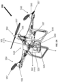
- a representative aerial vehicle 500 comprising a vehicle body 510 and an apparatus for stabilizing an imaging device attached to the vehicle body comprising; an optical unit and a non-optical unit, said apparatus comprising; a frame assembly 520 having a mounting member 525, rotatably coupled to the optical unit of the imaging device 540, and supporting the entire imaging device as a whole, wherein the frame assembly is configured to permit the imaging device to rotate about at least a first rotational axis 501 and a second rotational axis 502, the optical unit comprising at least a lens 521 (not shown), and a photosensor 523 (not shown) that is optically coupled to the lens; and a motor assembly 530 coupled to the frame assembly, the motor assembly configured to directly drive the frame assembly so as to permit the optical unit to rotate about at least the first rotational axis or the second rotational axis.
- the device is configured with a third motor assembly 536 coupled to the frame assembly, the motor assembly configured to directly drive the frame assembly 570 so as to permit the optical unit 545 to rotate about a third rotational axis 503, as illustrated in FIGS. 5B and 5C .
- an aerial vehicle comprising a vehicle body and an apparatus for stabilizing at least a portion of an imaging device attached to the vehicle body that comprises; an optical unit and a non-optical unit, said optical unit and non-optical unit constituting the entire imaging device, said apparatus comprising; a frame assembly having a volume that is less than that of a frame assembly required to support the entire imaging device having the optical unit and the non-optical unit, wherein the frame assembly is configured to support the optical unit of the imaging device, wherein the frame assembly is configured to permit rotation of the optical unit about at least a first rotational axis and a second rotational axis, and wherein the optical unit comprises at least a lens and a photosensor that is optically coupled to the lens; and a motor assembly operably connected to the frame assembly, wherein the motor assembly is configured to drive the frame assembly so as to permit rotation of the optical unit about at least the first rotational axis or the second rotational axis.
- the device is configured with a third motor assembly 536 coupled to the frame assembly, the motor assembly configured to directly drive the frame assembly 570 so as to permit the optical unit 545 to rotate about a third rotational axis 503, as illustrated in FIGS. 5B and 5C .
- the frame assembly 570 is configured to support the optical unit 545 of the imaging device, without supporting the entire imaging device 540 as a whole, wherein the frame assembly is configured to permit the optical unit to rotate about at least a first rotational axis 501 and a second rotational axis 502, and a third rotational axis 503, the optical unit comprising at least a lens 521 and a photosensor 523 that is optically coupled to the lens; and motor assemblies 532, 534 coupled to the frame assembly, the motor assemblies configured to directly drive the frame assembly 570 so as to permit the optical unit 545 to rotate about at least the first rotational axis 502, or the second rotational axis 501.
- a third motor assembly 536 is coupled to the frame assembly, to permit the optical unit 545 to rotate about a third rotational axis 503.
- an aerial vehicle comprising a vehicle body and an apparatus for stabilizing at least a portion of an imaging device attached to the vehicle body that comprises an optical unit and a non-optical unit, said optical unit and non-optical unit constituting the entire imaging device, said apparatus comprising; a frame assembly supporting the optical unit of the imaging device, wherein the frame assembly is configured to permit rotation of the optical unit about at least a first rotational axis and a second rotational axis, and wherein the optical unit comprises at least a lens and a photosensor that is optically coupled to the lens; and a motor assembly operably connected to the frame assembly, wherein the motor assembly is configured to drive the frame assembly so as to permit rotation of the optical unit about at least the first rotational axis or the second rotational axis, and wherein the motor assembly consumes a minimum amount of energy that is less than that required to drive a frame assembly supporting the entire imaging device.
- said vehicle comprises an engine 555 configured to drive movement of said aerial vehicle.
- the engine is configured within said vehicle body.
- the engine is configured as a component of a rotor assembly 550.
- the apparatus for stabilizing at least a portion of an imaging device also comprises shock absorbers 571 such as illustrated in FIG. 5B .
- Shock absorbers can be placed strategically on the frame, preferably between the frame and the moving vehicle, at the moiunting surface, to insulate the imaging device, or more importantly, the optical unit from vibration, shock, sway, tremor, shaking, or jerking movement.
- the aerial vehicle is an unmanned aerial vehicle capable of controlled flight without requiring an occupant of the aerial vehicle.
- the aerial vehicle comprises one or more blades 557 configured to rotate to provide lift to the unmanned aerial vehicle.
- the non-optical unit is supported by the vehicle body without being supported by the frame assembly.
- the optical unit and non-optical units can be physically separated and communicate by either tethered (wired) 101 or wireless communication means 101c.
- a method of stabilizing at least a portion of an imaging device comprising; supporting the optical unit of the imaging device using a frame assembly without supporting the entire imaging device as a whole, as illustrated in FIGS. 1A and 5B , wherein the frame assembly is configured to permit rotation of the optical unit about at least a first rotational axis and a second rotational axis, and wherein the optical unit comprises at least a lens and a photosensor that is optically coupled to the lens; and driving the frame assembly using a motor assembly operably connected to the frame assembly, thereby causing rotation of the optical unit about at least the first rotational axis or the second rotational axis.
- the optical unit and the non-optical unit are electrically coupled to each other.
- the optical unit 120, 540 further comprises at least one of a filter, positional sensor, storage medium 105, battery 104, zooming motor, circuitry 103, power supply, processor, or housing.
- the optical unit further comprises a weight adapted to provide stability for the optical unit.
- the weight comprises a battery.
- the battery is configured to provide power necessary for operation of an aerial vehicle or the imaging device.
- the non-optical unit comprises the storage medium 105.
- the non-optical 108 unit does not include a lens or a photosensor.
- the non-optical unit comprises at least one of a positional sensor, power supply, battery 104, motors, circuitry 103, display, processor, or housing 109.
- At least one of the first rotational axis and the second rotational axis corresponds to a pitch, roll, or yaw axis of the optical unit.
- the method further comprises driving the frame assembly using the motor assembly, thereby causing rotation of the optical unit about a third rotational axis.
- the third rotational axis corresponds to at least one of a pitch, roll or yaw axis of the optical unit.
- said method comprises receiving a signal from at least one positional sensor for indicative of an inclination angle of the non-optical unit and/or the optical unit in order to correct an inclination angle of the optical unit.
- said method further comprises reducing more movement experienced by the optical unit than the amount of movement experienced by the non-optical unit.
- said movement comprises at least one of vibration, shock, sway, tremor, shaking, or jerking movement.
- said method further comprises capturing and storing an image using both the optical unit 120 and non-optical unit 108.
- a method of stabilizing at least a portion of an imaging device that comprises an optical unit and a non-optical unit, said optical unit and non-optical unit constituting the entire imaging device, said method comprising; supporting the optical unit of the imaging device using a frame assembly, the frame assembly having a volume that is less than that of a frame assembly required to support the entire imaging device having the optical unit and the non-optical unit, wherein the frame assembly is configured to permit rotation of the optical unit about at least a first rotational axis and a second rotational axis, and wherein the optical unit comprises at least a lens and a photosensor that is optically coupled to the lens; and driving the frame assembly using a motor assembly operably connected to the frame assembly, thereby causing rotation of the optical unit about at least the first rotational axis or the second rotational axis.
- the optical unit and the non-optical unit are electrically coupled to each other.
- the optical unit further comprises at least one of a filter, positional sensor, storage medium, battery, zooming motor, circuitry, power supply, processor, or housing.
- the optical unit further comprises a weight adapted to provide stability for the optical unit.
- the weight comprises a battery 104.
- the battery is configured to provide power necessary for operation of an aerial vehicle or the imaging device.
- the non-optical unit comprises a storage medium.
- the non-optical 108 unit does not include a lens or a photosensor.
- the non-optical unit comprises at least one of a positional sensor, power supply, battery, motors, circuitry, display, processor, or housing.
- At least one of the first rotational axis and the second rotational axis corresponds to a pitch, roll, or yaw axis of the optical unit.
- the method further comprises driving the frame assembly using the motor assembly, thereby causing rotation of the optical unit about a third rotational axis.
- the third rotational axis corresponds to at least one of a pitch, roll or yaw axis of the optical unit.
- said method comprises receiving a signal from at least one positional sensor for indicative of an inclination angle of the non-optical unit and/or the optical unit in order to correct an inclination angle of the optical unit.
- said method further comprises reducing more movement experienced by the optical unit than the amount of movement experienced by the non-optical unit.
- said movement comprises at least one of vibration, shock, sway, tremor, shaking, or jerking movement.
- said method further comprises capturing and storing an image using both the optical unit and non-optical unit.
- a method of stabilizing at least a portion of an imaging device that comprises an optical unit and a non-optical unit, said method comprising; supporting the optical unit of the imaging device using a frame assembly, wherein the frame assembly is configured to permit rotation of the optical unit about at least a first rotational axis and a second rotational axis, and wherein the optical unit comprises at least a lens and a photosensor that is optically coupled to the lens; and driving the frame assembly using a motor assembly operably connected to the frame assembly, the motor assembly consuming a minimum amount of energy that is less than that required to drive a frame assembly supporting the entire imaging device, thereby causing rotation of the optical unit about at least the first rotational axis or the second rotational axis.
- the optical unit and the non-optical unit are electrically coupled to each other.
- the optical unit further comprises at least one of a filter, positional sensor, storage medium, battery, zooming motor, circuitry, power supply, processor, or housing.
- the optical unit further comprises a weight adapted to provide stability for the optical unit.
- the weight comprises a battery.
- the battery is configured to provide power necessary for operation of an aerial vehicle or the imaging device.
- the non-optical unit comprises a storage medium.
- the non-optical unit does not include a lens or a photosensor.
- the non-optical unit comprises at least one of a positional sensor, power supply, battery, motors, circuitry, display, processor, or housing.
- At least one of the first rotational axis and the second rotational axis corresponds to a pitch, roll, or yaw axis of the optical unit.
- the method further comprises driving the frame assembly using the motor assembly, thereby causing rotation of the optical unit about a third rotational axis.
- the third rotational axis corresponds to at least one of a pitch, roll or yaw axis of the optical unit.
- said method comprises receiving a signal from at least one positional sensor for indicative of an inclination angle of the non-optical unit and/or the optical unit in order to correct an inclination angle of the optical unit.
- said method further comprises reducing more movement experienced by the optical unit than the amount of movement experienced by the non-optical unit.
- said movement comprises at least one of vibration, shock, sway, tremor, shaking, or jerking movement.
- said method further comprises capturing and storing an image using both the optical unit and non-optical unit.
- a method of stabilizing at least a portion of an imaging device comprising providing an optical unit comprising at least a lens and a photosensor that is optically coupled to the lens; electrically coupling a non-optical unit to the optical unit; and moving the optical unit relative to the non-optical unit via actuation of a frame assembly coupled to said optical unit.
- the optical unit further comprises at least one of a filter, positional sensor, storage medium, battery, zooming motor, circuitry, power supply, processor, or housing.
- the optical unit further comprises a weight adapted to provide stability for the optical unit.
- the weight comprises a battery.
- the battery is configured to provide power necessary for operation of an aerial vehicle or the imaging device.
- the non-optical unit comprises a storage medium.
- the non-optical unit does not include a lens or a photosensor.
- the non-optical unit comprises at least one of a positional sensor, power supply, battery, motors, circuitry, display, processor, or housing.
- At least one of the first rotational axis and the second rotational axis corresponds to a pitch, roll, or yaw axis of the optical unit.
- the method further comprises driving the frame assembly using the motor assembly, thereby causing rotation of the optical unit about a third rotational axis.
- the third rotational axis corresponds to at least one of a pitch, roll or yaw axis of the optical unit.
- said method comprises receiving a signal from at least one positional sensor for indicative of an inclination angle of the non-optical unit and/or the optical unit in order to correct an inclination angle of the optical unit.
- said method further comprises reducing more movement experienced by the optical unit than the amount of movement experienced by the non-optical unit.
- said movement comprises at least one of vibration, shock, sway, tremor, shaking, or jerking movement.
- said method further comprises capturing and storing an image using both the optical unit and non-optical unit.
- an aerial vehicle comprising a vehicle body and a frame assembly connected to said vehicle body, wherein said frame assembly comprises a battery attached thereto and said frame assembly is configured to hold and stabilize an imaging device having an optical unit, and wherein the battery is attached to the assembly at a location separate from that of the imaging device, and wherein the battery is configured to provide power for operation of the aerial vehicle or the imaging device.
- the battery is configured to provide power for operation of the aerial vehicle. In some embodiments the battery has a weight that provides stability to said optical unit of said imaging device.
Landscapes
- Engineering & Computer Science (AREA)
- Multimedia (AREA)
- Signal Processing (AREA)
- Aviation & Aerospace Engineering (AREA)
- Mechanical Engineering (AREA)
- Remote Sensing (AREA)
- Microelectronics & Electronic Packaging (AREA)
- Physics & Mathematics (AREA)
- General Physics & Mathematics (AREA)
- Studio Devices (AREA)
- Accessories Of Cameras (AREA)
- Adjustment Of Camera Lenses (AREA)
Description
- For many years, both amateur and professional photographers and videographers have struggled with blurred images due to instability of the camera mounting, motion by the user, motion and vibration transferred to the camera from a mobile transport, or some combination of these issues.
- Currently, there exists primarily four methods of vibration dampening commonly employed in photography and videography to reduce the effects of vibration on the picture: software stabilization, lens stabilization, sensor stabilization, and overall shooting equipment stabilization.
- Lens stabilization and sensor stabilization are now widely applied in many consumer digital cameras. The general principle of lens stabilization is to eliminate the shake on the lens by controlling horizontal displacement or rotation of a certain lens or some lenses; and sensor stabilization is intended to offset the vibration by enabling a photosensitive sensor to translate or rotate. Lens stabilization and sensor stabilization are both implemented within the shooting equipment, requiring minimal volume. However, due to structural limitations and limited travel range of the movement (including translation and rotation) of the lens or sensor, vibration with large amplitude or at high frequency is still difficult to eliminate completely, particularly when carrying the shooting equipment or mounting video equipment on a moving vehicle.
- The effectiveness of software stabilization is limited. An extremely large amount of computation is required in the shake elimination process for video, often resulting in only a limited beneficial effect.
- Overall, methods applied to shooting equipment stabilization mainly perform stabilization for the shooting equipment on three rotation axes, with a large rotation range and reasonably quick response. This can substantially overcome the drawbacks in lens stabilization and sensor stabilization. However, as stabilization is performed for the entire set of (video) equipment, the structure is usually quite large, making it inconvenient to carry or use, and requires very large amounts of energy (batteries) to drive the stabilizing equipment, making it inconvenient, impractical and relatively expensive for most commercial and personal applications.
-
US 2004/ 183907 A1 describes an optical block assemblies having single or multistage folded light path lens assemblies that may be implemented to allow an optical block assembly to occupy significantly less space and/or present reduced rotational inertia to an electrical articulating mechanism. An optical assembly may be so configured for closed circuit television applications or in any other suitable video imaging application including, but not limited to, applications involving non-articulated or articulated cameras such as normal filming (e.g., motion picture film cameras or studio television cameras), camcorders, military targeting or imaging devices, etc. -
US 2012/0316685 A1 describes a gimbal system for mounting a gimbal apparatus to a support platform with a mount assembly. The mount assembly may include first and second bar assemblies that are rotationally coupled to each other by a pair of gears. -
US 2005/185089 A1 describes a remote camera head that has a tilt frame attachable to a pan frame at multiple positions. A roll frame is attachable to the tilt frame at multiple positions. The camera head can be expanded or reduced in size. - The present invention relates to an apparatus according to
independent claim 1, and to an aerial vehicle and to a method according to the other independent claims. Some of the preferred embodiments are described in the dependent claims, in the description and in the figures. - The novel features of the invention are set forth with particularity in the appended claims. A better understanding of the features and advantages of the present invention will be obtained by reference to the following detailed description that sets forth illustrative embodiments, in which the principles of the invention are utilized, and the accompanying drawings of which:
-
FIG. 1A is an illustrative isometric view of an exemplary stabilizing apparatus assembly. -
FIGs. 1B-1E are illustrative arrangements of optical and non-optical assemblies of imaging devices. -
FIG. 2 is an illustrative isometric view of an exemplary 3-axis stabilizing apparatus assembly -
FIG. 3 is an illustrative isometric view of an exemplary non-orthogonal 3-axis stabilizing apparatus assembly with an optical unit. -
FIG. 4 is a side view ofFigure 2 illustrating an exemplary orthogonal 3-axis stabilizing apparatus assembly with an optical unit. -
FIG. 5A is an illustrative ISO view of an exemplary aerial vehicle with a 2-axis stabilizing apparatus assembly comprising an imaging device mounted on the frame. -
FIG. 5B is an illustrative ISO view of an exemplary aerial exemplary vehicle with a 3-axis stabilizing apparatus assembly supporting the optical unit an imaging device mounted on the frame. -
FIG. 5C is an illustrative ISO view of an exemplary aerial vehicle with a 3-axis stabilizing apparatus assembly supporting an entire imaging device mounted on the frame. -
FIG. 6 is n illustrative view of an exemplary 2-axis stabilizing frame assembly an entire imaging device. - Apparatus and methods have been developed to reduce the effects of vibration and allow for the size reduction of stabilization equipment for photography and videography, by separating the components of the imaging device, reducing the relative mass of all components involved, and focusing the majority of the stabilization efforts near the optics components of the imaging device.
- The apparatus incorporates the use of positional sensors wherein a positional sensor shall mean: motion sensors (accelerometers) and rotation sensors (gyroscopes) or other inertial sensors to continuously calculate via dead reckoning the position, orientation, and velocity (direction and speed of movement) of a moving object without the need for external references"; e.g.: "state information". Positional sensors shall also include sensors that use external references such as compasses, and GPS (global positioning system) sensors, and the like.
- In addition, the apparatus incorporates controllers for generating one or more motor signals for driving the movement of the frame assembly of the apparatus, based on the state information generated by the sensors.
- An apparatus for stabilizing at least a portion of an imaging device has been developed. The imaging device comprises an optical unit and a non-optical unit. The apparatus comprises a frame assembly rotatably coupled to the optical unit of the imaging device, wherein said frame is configured to permit the optical unit to rotate about at least a first rotational axis and a second rotational axis, the optical unit comprising at least a lens and a photosensor. Said apparatus comprising a frame assembly having a volume that is less than that of a frame assembly required to support the entire imaging device having the optical unit and the non-optical unit. In one embodiment, said frame assembly will have a volume that is no more than one half of that of a frame assembly required to support the entire imaging device. Said apparatus also having a motor assembly wherein the motor assembly consumes a minimum amount of energy that is less than that required to drive a frame assembly supporting the entire imaging device. In a preferred embodiment, said motor assembly will consume no more than one half of the amount of energy than that of a motor assembly required to drive a frame assembly supporting the entire imaging device. Said apparatus can be configured to be coupled to a moving vehicle, an aerial vehicle, or can be handheld.
- Provided herein, as shown in
FIG. 1A , is anexemplary apparatus 100 for stabilizing animaging device 115, (108 + 120) comprising anoptical unit 120 and anon-optical unit 108, said apparatus comprising: aframe assembly 110 rotatably coupled to theoptical unit 120 of the imaging device, without supporting the entire imaging device as a whole 115, wherein theframe assembly 110 configured to permit theoptical unit 120 to rotate about at least a firstrotational axis 102 and a secondrotational axis 104, theoptical unit 120 comprising at least alens 121 and aphotosensor 123 that is optically coupled to the lens; and amotor assembly frame assembly 110, the motor assembly configured to directly drive the frame assembly so as to permit the optical unit to rotate about at least the firstrotational axis 102 or the secondrotational axis 104. As shown, the non-optical unit is coupled to the frame assembly on abase 107, which can be on a completely different part of the frame, or even a remote location. - As a further illustration,
FIG.1B illustrates one possible configuration of animaging device 115, wherein theoptical unit 120 and thenon-optical unit 108 are physically separated, but coupled byoptical cabling 101 or wiring, and electrically coupled at eachend housing 109, abattery 104 andstorage media 105. Theoptical unit 120 comprises alens 121, and aphotosensor 123. - In some embodiments the
non-optical unit 108 of the imaging device is not mechanically coupled to the apparatus. It is understandable that once one realizes that the components of the imaging device can be physically separated, it is no longer necessary for both components to be physically located on the same apparatus. For example, theoptical unit 120 may be located on the apparatus, while thenon-optical unit 120 is located somewhere else, preferably nearby, but not necessarily. In some embodiments the optical unit and the non-optical unit are electrically coupled (FIG. 1B ). This may typically be accomplished by optical cabling orelectrical wiring 101. In some embodiments the optical unit and the non-optical unit are movable relative to each other. As shown inFIG. 1 and further illustrated inFIG. 1B , when the optical unit and non-optical unit are physically separated, and physically located on separate mounting bases, and/or separate axes of a multi-axis apparatus, such as described herein, the optical unit and non-optical unit can be configured to each other, by design. - In some embodiments, the non-optical unit of the imaging device is not mechanically coupled to the optical unit of the imaging device, as illustrated in
FIGS. 1C - 1E by other mean including but not limited towireless 101c communication between the optical unit and the non-optical unit. Such wireless means of communication include electromagnetic telecommunications, (i.e.: radio), and point-to-point, or point-to-multi-point wireless networking, or alternately, light (e.g.: infrared), magnetic, or electric fields. - In some embodiments, such as illustrated in
FIGS. 1C - 1E , theoptical unit 120 of theimaging device 115 further comprises at least one of a filter (not shown), positional sensor (not shown),storage medium 105,battery 104, zooming motor (not shown),circuitry 103, power supply (alternately 104), processor (not shown), or housing (not shown). Because the major components of the imaging device have been separated for this apparatus, it may be necessary to individually configure each major component with various sub-components, which may or may not be redundant to the other major component(s). Examples may include; positional sensors,storage media 105, a source ofpower 104, etc. Alternatively, some components will rarely if ever be needed in all major components. In still other embodiments, the optical unit of the imaging device further comprises a weight adapted to provide stability for the optical unit. Depending on the application and physical density, any number of sub-components may act in the dual capacity of a weight and their alternate, intended function. For example, in some embodiments, the weight may comprise abattery 104. - The non-optical unit comprises
storage medium 105. In some embodiments, the non-optical 108 unit does not include alens 121, or aphotosensor 123, as illustrated inFIGS. 1B - 1E . In other embodiments, the non-optical unit of the imaging device comprises at least one of a positional sensor (not shown),battery 104, motors (not shown),circuitry 103, power supply, processor (not shown), orhousing 109. - At least one of the first
rotational axis 102 and the secondrotational axis 104 corresponds to a pitch, roll or yaw axis of the optical unit. In the invention as claimed, the frame assembly is further configured to permit the optical unit to rotate about a thirdrotational axis 106. In some embodiments, the third rotational axis corresponds to at least one of a pitch, roll, or yaw axis of the optical unit. Although specific axes of rotation have been illustrated inFIG.1 , one of skill in the art would recognize that the axes of rotation can be randomly substituted, as appropriate, to meet the needs of a given application; meaning X-axis (pitch) rotation can be substituted with Y-axis (roll) rotation, or Z-axis (yaw) rotation can be substituted with X-axis (pitch) rotation, etc. - Still further, in some embodiments, the apparatus further comprises one or more
positional sensors 122, wherein at least one of the one or more positional sensors is configured to detect state information associated with theoptical unit 120. In addition the apparatus further comprises a controller for generating one ormore motor signals 124 based on the state information associated with the optical unit. In some embodiments, the state information comprises translational or rotational movement information or positional information. - In still other embodiments, at least one of the positional sensors is configured to detect state information associated with the non-optical unit. This is useful for orienting the image generated by the imaging device in space, e.g., especially when the non-optical unit is mounted on a base (e.g.: 107) that may represent the horizontal or vertical axis of a carrier device.
- In still further embodiments, at least one of the one or more positional sensors is configured to measure movement associated with at least a pitch, roll, or yaw axis of the optical unit. In addition, at least one of the one or more positional sensors comprises an inertial sensor.
- In any one of the examples as illustrated in
FIGs. 2 ,3 ,4 , the rotational (pitch)axis X 202 of the first framemember mounting base 227 is orthogonally disposed relative to the rotational (roll)axis Y 204, for example, to allow the motors to easily and timely adjust the rotation of the frame assembly. In the claimed invention, the rotational axes are not orthogonally disposed to each other such as inFIG.3 . - In a example, as illustrated in
FIG. 4 , the rotational (roll)axis X 404 is orthogonally disposed relative to the rotational (yaw)axis Y 406, for example, to allow the motors to easily and timely adjust the rotation of the frame assembly. In the claimed invention, the rotational axes are not orthogonally disposed to each other such as inFIG.3 . - To further increase the stability for the payload device, the center of gravity of the first frame
member mounting base 308 and thepayload device 309 as a whole is preferably located on the rotational (pitch)axis X 302 of the first frame member, as illustrated inFIG. 3 . In some embodiments, the pitch axis intersects with thepayload device 309. It is appreciated that when the center of gravity of the first frame member and thepayload device 309 is positioned on therotational axis X 302 of the first frame member, the rotation of the first frame member does not generate any torque. In other words, the first frame member is not likely to have any swing movement caused by the torque. Thus, the stability of the payload device is enhanced during rotation. In addition, in the preferred embodiment, when the carrier is moving smoothly, that is, when little or no motor drive stabilization is required, the first frame member and thepayload device 309 is also in a dynamically balanced state. - Similarly, to provide enhanced stability and avoid torque generated by rotation around the rotational Y (roll)
axis 304, in a preferred embodiment and as shown inFIG. 3 , the center of gravity of the first frame member, the second frame member and thepayload device 309 as a whole is located on therotational axis Y 304 of the second frame member. In some embodiments, the rotational Y (roll)axis 304 intersects with thepayload device 309. - It is also appreciated that in the afforementioned configuration of the frame assembly can provide near limitless ranges of motion for
axes payload device 309 to circumferentially rotate (e.g., up to 360 degrees, 720 degrees, or more, in any axis), for example, in order to perform panoramic photography. - In any of the preceding and subsequent embodiments, the apparatus can be configured to be coupled to a movable object. In some embodiments, the fixing points 118, 218, 318, 418 may be used to mount the
mointing base 201 to or to facilitate the carrying of the stabilizing platform by a carrier, such as an aerial vehicle, motor vehicle, ship, robot, human, or any other movable object. As another example, themointing base 201 may be handheld by a human, for example, to perform dynamic videography or photography. - A moveable object may be anything that can move relative to the earth. For example, moveable objects can be a wheeled-vehicle; a tracked-vehicle; a sliding or sledded vehicle; an aircraft; a hovercraft; a watercraft; or a spacecraft. Alternatively, a moving object can be a human being; a mammal; an aquatic animal; an amphibious animal; a reptile; a bird; or an invertebrate animal. Still further, a moving object can be relatively fixed, but still capable of movement, such as a tree, pole, or even a building that may be subject to swaying or vibration due to wind or even earthquakes.
- In addition, the apparatus is configured to reduce relatively more movement experienced by the optical unit caused by the movable object than the amount of movement experienced by the non-optical unit. This movement can include but limit one of vibration, shock, sway, tremor, shaking, or jerking movement. In some embodiments, the apparatus for stabilizing an imaging device comprising an optical unit and a non-optical unit is configured to be handheld. Such apparatus can produce a more stable platform for vibration-resistant or even vibration-free imagery by, e.g., isolating the optical unit of an imaging device. Since a large proportion of the overall weight of an imaging device is associated with components and sub-components that are not directly associated with the lens and photosensor, the apparatus is designed to provide better vibration dampening and higher response rates to the smaller and lighter components of the optical unit alone.
- Still further, as specifically illustrated in
FIG. 1 , or implied in any of the preceding or subsequent embodiments, the frame assembly comprises a first stage connected to and supporting the optical unit, a second stage movable relative to the first stage, and the optical unit about the first rotational axis. In addition, the frame assembly can further comprise a third stage movable relative to the second stage about the second rotational axis. - As further illustrated in
FIG. 1 , provided herein is an apparatus for stabilizing at least a portion of an imaging device that comprises an optical unit and a non-optical unit, said apparatus comprising a frame assembly having a volume that is less than that of a frame assembly required to support the entire imaging device having the optical unit and the non-optical unit as potentially illustrated inFIGS 4 and5B , wherein the frame assembly is configured to support theoptical unit 120 of the imaging device, wherein the frame assembly is configured to permit rotation of the optical unit about at least a firstrotational axis 102 and a secondrotational axis 104, and wherein the optical unit comprises at least alens 121 and a photosensor 123 that is optically coupled to the lens; and wherein themotor assembly 112 or 114 (not shown) is configured to drive theframe assembly 110 so as to permit rotation of theoptical unit 120 about at least the firstrotational axis 102 or the secondrotational axis 104. - In some embodiments, a frame assembly has a volume that is preferably one half or less than that of a frame assembly required to support the entire imaging device. For example, miniaturized components of the optical unit, described herein, and illustrated in
FIG. 1 , have the following proportions, wherein a 1/2.33" photosensor having an imaging area of 6.13 x 4.6 mm, weighs 0.6g. The entire optical unit (photosensor lens and structure used secure lens and photosensor), plus a three-axis gyroscope and three-axis accelerometer, weigh about 15g. The overall dimensions would be approximately 2.5cm x 1.8cm x 3cm. The non-optical unit of an imaging system designed to work with this optical unit would have the outer dimension volumes of 77mm x 67mm x 80mm, and have a total weight of 80g (excluding the optical component). In addition, the motor along each axis of a 3-axis frame assembly has a rated power of only about 2w. The invention described herein compares very favorably to other successful "compact" imaging systems having a 1/2.33" photosensor such as one by GoPro®, wherein the dimensions are 58.4 x 38.1 x 20.3 mm and the weights are approximately 75g. For stabilizing the whole GoPro camera, currently existing 2-axis platforms weigh 200g (excluding the camera), with an outer dimensional volume of 93mm x 85mm x 100mm. The much larger motors required to drive the larger frames require 5w power levels for each motor along each axis. - By separating the optical unit from the non-optical unit, the volume of the frame assembly required for stabilization is less than that is required to support the entire imaging device. In some embodiment, the volume of the frame assembly is reduced by 10%, 20%, 30%, 40%, 50%, 60%, 70%, 100% or more as compared to the volume of a frame assembly for supporting the entire imaging device. In other embodiments, the volume of the frame assembly is merely ½, 1/3, ¼, 1/5 or less of that is required for supporting the entire imaging device having the optical and non-optical units as a whole.
- In other embodiment, the minimum amount of the energy required by a subject motor to drive the subject frame assembly is less than that is required to drive a frame assembly supporting the entire imaging device. In some embodiments, the motor consumes a minimum amount of energy that is 90%, 80%, 70%, 60%, 50%, 40%, 30%, 20%, 10% or even less than that which is required for a motor driving a frame assembly supporting the whole imaging device (e.g., with optical and the non-optical units as an integral piece). In some embodiments, the minimum amount of energy required by the subject motor is less than 5W, 4W, 3W, 2W, 1W power to drive along an axis of a frame assembly.
- In some embodiments the non-optical unit of the
imaging device 115 is not mechanically coupled to the apparatus. In some embodiments the optical unit and the non-optical unit are electrically coupled. In some embodiments the optical unit and the non-optical unit are movable relative to each other. As shown inFIG. 1 , when the optical unit and non-optical unit are physically separated, and physically located on separate mounting bases, and/or separate axes of a multi-axis apparatus, such as described herein, the optical unit and non-optical unit will move relative to each other, by design. - As previously described, in some embodiments, the
non-optical unit 108 of theimaging device 115 is not mechanically coupled to the optical unit of the imaging device, as illustrated in inFIGS. 1B - 1E . Employing any one of a variety of available communication technologies, the apparatus described herein can employ a means ofwireless communication 101c between the optical unit and the non-optical unit. Such wireless means of communication include electromagnetic telecommunications, (i.e.: radio), and point-to-point, or point-to-multi-point wireless networking, or alternately, light (e.g.: infrared), magnetic, or electric fields. - In some embodiments the
optical unit 120 of theimaging device 115 further comprises at least one of a filter, positional sensor, storage medium, battery, zooming motor, circuitry, power supply, processor, or housing. In still other embodiments, the optical unit of the imaging device further comprises a weight adapted to provide stability for the optical unit. In still other embodiments, the weight comprises a battery. - The non-optical unit comprises a storage medium. In some embodiments, the non-optical unit does not include a lens or a photosensor. In other embodiments, the non-optical unit of the imaging device comprises at least one of a positional sensor, battery, motors, circuitry, power supply, processor, or housing.
- In some embodiments, at least one of the first rotational axis and the second rotational axis corresponds to a pitch, roll or yaw axis of the optical unit. In the invention as claimed, the frame assembly is further configured to permit the optical unit to rotate about a third rotational axis. In some embodiments, the third rotational axis corresponds to at least one of a pitch, roll, or yaw axis of the optical unit.
- Still further, in some embodiments, the apparatus further comprises one or more positional sensors, wherein at least one of the one or more positional sensors is configured to detect state information associated with the optical unit. In addition the apparatus further comprises a controller for generating one or more motor signals based on the state information associated with the optical unit. In some embodiments, the state information comprises translational or rotational movement information or positional information.
- In still other embodiments, at least one of the positional sensors is configured to detect state information associated with the non-optical unit.
- In still further embodiments, at least one of the one or more positional sensors is configured to measure movement associated with at least a pitch, roll, or yaw axis of the optical unit. In addition, at least one of the one or more positional sensors comprises an inertial sensor.
- In any of the stated embodiments, the apparatus is configured to be coupled to a movable object. A moveable object may be anything that can move relative to the earth. For example, moveable objects can be a wheeled-vehicle; a tracked-vehicle; a sliding or sledded vehicle; an aircraft; a hovercraft; a watercraft; or a spacecraft. Alternatively, a moving object can be defined as a human being; a mammal; an aquatic animal; an amphibious animal; a reptile; a bird; or an invertebrate animal. Still further, a moving object can be relatively fixed, but still capable of movement, such as a tree, pole, or even a building that may be subject to swaying or vibration due to wind or even earthquakes.
- In addition, the apparatus is configured to reduce relatively more movement experienced by the optical unit caused by the movable object than the amount of movement experienced by the non-optical unit. This movement is often described as one of vibration, shock, sway, tremor, shaking, or jerking movement. In some embodiments, the apparatus for stabilizing an imaging device comprising an optical unit and a non-optical unit is configured to be handheld. More specifically, a novel aspect of the apparatus is the inherent ability to uniquely isolate the optical unit thus producing a more stable platform for vibration-free imagery. Since a large proportion of the overall weight of an imaging device is associated with components and sub-components that are not directly associated with the lens and photosensor, the apparatus is designed to provide better vibration dampening and higher response rates to the smaller and lighter components of the optical unit alone.
- As stated previously, the apparatus is configured to be coupled to a movable object. In addition, the apparatus is configured to reduce relatively more movement experienced by the optical unit caused by the movable object than the amount of movement experienced by the non-optical unit. In some embodiments, the apparatus for stabilizing at least a portion of an imaging device comprising an optical unit and a non-optical unit is configured to be handheld.
- Still further, in any of the preceding embodiments, the frame assembly comprises a first stage connected to and supporting the optical unit, and a second stage movable relative to the first stage and the optical unit about the first rotational axis. In addition, the frame assembly comprises a third stage movable relative to the second stage about the second rotational axis.
- Provided herein is an apparatus for stabilizing at least a portion of an imaging device that comprises an optical unit and a non-optical unit, said apparatus comprising: a frame assembly supporting the optical unit of the imaging device, wherein the frame assembly is configured to permit rotation of the optical unit about at least a first rotational axis and a second rotational axis, and wherein the optical unit comprises at least a lens and a photosensor that is optically coupled to the lens; and a motor assembly operably connected to the frame assembly, wherein the motor assembly is configured to drive the frame assembly so as to permit rotation of the optical unit about at least the first rotational axis or the second rotational axis, and wherein the motor assembly consumes a minimum amount of energy that is less than that required to drive a frame assembly supporting the entire imaging device.
- As further illustrated in
Fig. 1 , in a preferred embodiment, the motor assembly will preferably consume no more than one half of the amount of energy than that of a motor assembly required to drive a frame assembly supporting the entire imaging device. - Referring to the previous Example 1, the motor along each axis of a 3-axis frame assembly of the subject invention has a rated power of only about 2w. An alternative illustrative embodiment for a 3-axis frame is illustrated in
FIG. 2 , (no imaging device shown). - Whereas by comparison, the motors required to drive the referenced 2-axis frame assembly for a comparable "compact" GoPro camera are significantly larger. The much larger motors required to drive the larger 2-axis frames require 5w power levels for each motor along each axis. An example of larger 2-axis frame required for a comparable frame assembly supporting the entire imaging device is seen in
FIG. 6 . - In some embodiments the non-optical unit of the imaging device is not mechanically coupled to the apparatus. In some embodiments the optical unit and the non-optical unit are electrically coupled. In some embodiments the optical unit and the non-optical unit are movable relative to each other.
- As previously described, in some embodiments, the non-optical unit of the imaging device is not mechanically coupled to the optical unit of the imaging device. Employing any one of a variety of available communication technologies, the apparatus described herein can employ a means of wireless communication between the optical unit and the non-optical unit. Such wireless means of communication include electromagnetic telecommunications, (i.e.: radio), and point-to-point, or point-to-multi-point wireless networking, or alternately, light (e.g.: infrared), magnetic, or electric fields.
- In some embodiments the optical unit of the imaging device further comprises at least one of a filter, positional sensor, storage medium, battery, zooming motor, circuitry, power supply, processor, or housing. In still other embodiments, the optical unit of the imaging device further comprises a weight adapted to provide stability for the optical unit. In still other embodiments, the weight comprises a battery.
- The non-optical unit comprises a storage medium. In some embodiments, the non-optical unit does not include a lens or a photosensor. In other embodiments, the non-optical unit of the imaging device comprises at least one of a positional sensor, battery, motors, circuitry, power supply, processor, or housing.
- In some embodiments, at least one of the first rotational axis and the second rotational axis corresponds to a pitch, roll or yaw axis of the optical unit. The frame assembly is further configured to permit the optical unit to rotate about a third rotational axis. In some embodiments, the third rotational axis corresponds to at least one of a pitch, roll, or yaw axis of the optical unit.
- Still further, in some embodiments, the apparatus further comprises one or more positional sensors, wherein at least one of the one or more positional sensors is configured to detect state information associated with the optical unit. In addition the apparatus further comprises a controller for generating one or more motor signals based on the state information associated with the optical unit. In some embodiments, the state information comprises translational or rotational movement information or positional information.
- In still other embodiments, at least one of the positional sensors is configured to detect state information associated with the non-optical unit.
- In still further embodiments, at least one of the one or more positional sensors is configured to measure movement associated with at least a pitch, roll, or yaw axis of the optical unit. In addition, at least one of the one or more positional sensors comprises an inertial sensor.
- In some of the preceding embodiments, the apparatus is configured to be coupled to a movable object. In addition, the apparatus is configured to reduce relatively more movement experienced by the optical unit caused by the movable object than the amount of movement experienced by the non-optical unit. In some embodiments, the apparatus for stabilizing at least a portion of an imaging device comprising an optical unit and a non-optical unit is configured to be handheld.
- Still further, in some of the preceding embodiments, the frame assembly comprises a first stage connected to and supporting the optical unit, and a second stage movable relative to the first stage and the optical unit about the first rotational axis. In addition, the frame assembly comprises a third stage movable relative to the second stage about the second rotational axis.
- In some embodiments of the apparatus, said energy is less than the amount of energy required to drive the frame assembly when the entire imaging device apparatus as a whole is supported by the frame assembly.
- In some embodiments wherein an apparatus for stabilizing at least a portion of an imaging device that comprises an optical unit and a non-optical unit, and wherein the motor assembly consumes a minimum amount of energy that is less than that required to drive a frame assembly supporting the entire imaging device, said energy is less than the amount of energy required to drive the frame assembly when the entire imaging device apparatus as a whole is supported by the frame assembly.
- As suggested above, at least one embodiment of the apparatus comprises a frame assembly configured to support an entire imaging device, wherein the components have been separated and are placed at different locations on the frame. For example, as shown in
FIG. 1 , the non-optical unit is placed on thebase 107, on the Z-axis frame, whereas the optical unit is connected to the X-axis frame. In this configuration, the mass of the non-optical component can be completely isolated from the optical unit, thus allowing for a mixture of frame assembly components, with larger motors and frame base on the Z-plane, and the use of smaller configuration frame components below the Z-plane and subsequently use motors that consume less energy to drive the frame controlling only the optical unit movements. This example is only meant as one illustrative example of the numerous possible configurations and sub-configurations which are now possible. - Provided herein is an imaging device comprising an
optical unit 309 which comprises at least a lens and a photosensor that is optically coupled to the lens; and a non-optical unit that is electrically coupled to the optical unit (not-shown), wherein the optical unit is movable relative to the non-optical unit via actuation of aframe assembly 300 coupled to said optical unit, as previously illustrated inFIG. 1 . - In some embodiments, the non-optical unit is not mechanically coupled to the frame assembly. As shown in
FIG. 3 , a representative three-axis frame assembly 300 is illustrated with anoptical unit 309 coupled to theX-axis 302 of the frame in acarrier bracket 308, however, the non-optical unit is remotely located somewhere off the frame. As described previously, the non-optical unit and optical unit are illustrated in a wireless communication set-up. - As with prior examples, the illustrative frame has
drive motors positional sensors 322 and a at least onecontroller 324 for generating one or more motor signals for driving the movement of the frame assembly of the apparatus, based on the state information generated by the sensors. - Further, as illustrated by rotational symbols α and β the portion of the frame assembly controlling the movement of the optical unit has freedom to move in a rotation angle (α) between Z 306 (yaw) & Y 304 (roll) axes, and in non-right angle of rotation (β), resulting in net attitudinal translational movement separate from the non-optical unit, whether the non-optical unit is coupled to the frame or located remotely.
- Additionally,
FIG. 3 andFIG. 4 illustrate a means for alternative translational and additudinal movement by providingadditional rotation arms arm extensions - In some embodiments, the optical unit further comprises at least one of a filter, positional sensor, storage medium, battery, zooming motor, circuitry, power supply, processor, or housing. In other embodiments, the optical unit further comprises a weight adapted to provide stability for the optical unit. In some embodiments the weight comprises a battery.
- The non-optical unit comprises a storage medium. In some embodiments, the non-optical unit does not include a lens or a photosensor. In other embodiments, the non-optical unit of the imaging device comprises at least one of a positional sensor, battery, motors, circuitry, power supply, processor, or housing.
- In some embodiments of the imaging device, the
optical unit 309, is movable about a firstrotational axis 302 and a secondrotational axis 304 via the actuation of the frame assembly and the optical unit is movable about a thirdrotational axis 306 via the actuation of the frame assembly. - The optical unit is movable about a third rotational axis via the actuation of the frame assembly and the third rotational axis corresponds to at least one of a pitch, roll, or yaw axis of the optical unit.
- In still further embodiments of the imaging device, the state information associated with the optical unit is detectable by one or more
positional sensors 322 and said state information associated with the optical unit is used to generate one or more motor signals via thecontroller 324 that drive the actuation of the frame assembly. Said state information comprises translational or rotational movement information or positional information. In addition, state information associated with the non-optical unit is detectable by one or more positional sensors. - In still further embodiments of the imaging device, at least one of the one or more positional sensors is configured to measure movement associated with at least a pitch, roll, or yaw axis of the optical unit, and at least one of the one or more positional sensors comprises an inertial sensor.
- In some embodiments, the frame assembly of the imaging device is configured to be coupled to a movable object. As illustrated in
FIGS. 3 and4 multiple fixing points 318, 418 are provide on a Z-axis base 316, as one possible location for coupling a frame assembly to a moveable object. - In some embodiments of the imaging device, the optical unit and the non-optical unit are contained within a single housing. As shown in
FIG. 4 , aminiaturized imaging device 459 is contained within thecarrier bracket 431 and driven about a first axis with afirst driving member 432 and one or morepositional sensors 422. In other embodiments, the optical unit and the non-optical unit are not contained within a single housing. In this embodiment, the imaging device has a complete range of multi-axis rotational and translational movement with the ability to pivot about a firstrotating axis 429 and the rotational axis of the first drivingmember 432. Additionally, roll motion is provided by the second drive motor andpositional sensor controller 424. And finally, yaw motioon is provided by athird drive motor 434 andpositional sensor 422, allowing the imaging device to pivot about theextension arms - In still other embodiments of the
imaging device 459, the optical unit and the non-optical unit are both utilized to capture and store an image. - As shown in
FIG. 5A , a representativeaerial vehicle 500 is provided comprising avehicle body 510 and an apparatus for stabilizing an imaging device attached to the vehicle body comprising; an optical unit and a non-optical unit, said apparatus comprising; aframe assembly 520 having a mountingmember 525, rotatably coupled to the optical unit of theimaging device 540, and supporting the entire imaging device as a whole, wherein the frame assembly is configured to permit the imaging device to rotate about at least a firstrotational axis 501 and a secondrotational axis 502, the optical unit comprising at least a lens 521 (not shown), and a photosensor 523 (not shown) that is optically coupled to the lens; and amotor assembly 530 coupled to the frame assembly, the motor assembly configured to directly drive the frame assembly so as to permit the optical unit to rotate about at least the first rotational axis or the second rotational axis. - The device is configured with a
third motor assembly 536 coupled to the frame assembly, the motor assembly configured to directly drive theframe assembly 570 so as to permit theoptical unit 545 to rotate about a thirdrotational axis 503, as illustrated inFIGS. 5B and5C . - Provided herein is an aerial vehicle comprising a vehicle body and an apparatus for stabilizing at least a portion of an imaging device attached to the vehicle body that comprises; an optical unit and a non-optical unit, said optical unit and non-optical unit constituting the entire imaging device, said apparatus comprising; a frame assembly having a volume that is less than that of a frame assembly required to support the entire imaging device having the optical unit and the non-optical unit, wherein the frame assembly is configured to support the optical unit of the imaging device, wherein the frame assembly is configured to permit rotation of the optical unit about at least a first rotational axis and a second rotational axis, and wherein the optical unit comprises at least a lens and a photosensor that is optically coupled to the lens; and a motor assembly operably connected to the frame assembly, wherein the motor assembly is configured to drive the frame assembly so as to permit rotation of the optical unit about at least the first rotational axis or the second rotational axis. The device is configured with a
third motor assembly 536 coupled to the frame assembly, the motor assembly configured to directly drive theframe assembly 570 so as to permit theoptical unit 545 to rotate about a thirdrotational axis 503, as illustrated inFIGS. 5B and5C . - As shown in
FIG. 5B , theframe assembly 570 is configured to support theoptical unit 545 of the imaging device, without supporting theentire imaging device 540 as a whole, wherein the frame assembly is configured to permit the optical unit to rotate about at least a firstrotational axis 501 and a secondrotational axis 502, and a thirdrotational axis 503, the optical unit comprising at least alens 521 and a photosensor 523 that is optically coupled to the lens; andmotor assemblies frame assembly 570 so as to permit theoptical unit 545 to rotate about at least the firstrotational axis 502, or the secondrotational axis 501. In addition, athird motor assembly 536 is coupled to the frame assembly, to permit theoptical unit 545 to rotate about a thirdrotational axis 503. - Provided herein is an aerial vehicle comprising a vehicle body and an apparatus for stabilizing at least a portion of an imaging device attached to the vehicle body that comprises an optical unit and a non-optical unit, said optical unit and non-optical unit constituting the entire imaging device, said apparatus comprising; a frame assembly supporting the optical unit of the imaging device, wherein the frame assembly is configured to permit rotation of the optical unit about at least a first rotational axis and a second rotational axis, and wherein the optical unit comprises at least a lens and a photosensor that is optically coupled to the lens; and a motor assembly operably connected to the frame assembly, wherein the motor assembly is configured to drive the frame assembly so as to permit rotation of the optical unit about at least the first rotational axis or the second rotational axis, and wherein the motor assembly consumes a minimum amount of energy that is less than that required to drive a frame assembly supporting the entire imaging device.
- In some embodiments of the
aerial vehicle 500, said vehicle comprises anengine 555 configured to drive movement of said aerial vehicle. In some embodiments, the engine is configured within said vehicle body. In some embodiments, the engine is configured as a component of arotor assembly 550. - According to another aspect of the present invention the apparatus for stabilizing at least a portion of an imaging device also comprises
shock absorbers 571 such as illustrated inFIG. 5B . Shock absorbers can be placed strategically on the frame, preferably between the frame and the moving vehicle, at the moiunting surface, to insulate the imaging device, or more importantly, the optical unit from vibration, shock, sway, tremor, shaking, or jerking movement. - In some embodiments, the aerial vehicle is an unmanned aerial vehicle capable of controlled flight without requiring an occupant of the aerial vehicle.
- In some embodiments, the aerial vehicle comprises one or
more blades 557 configured to rotate to provide lift to the unmanned aerial vehicle. - In some embodiments of the aerial vehicle, the non-optical unit is supported by the vehicle body without being supported by the frame assembly. As illustrated in prior examples, and again in
FIG. 5B , orFIGS. 1B-1E , the optical unit and non-optical units can be physically separated and communicate by either tethered (wired) 101 or wireless communication means 101c. - Provided herein is a method of stabilizing at least a portion of an imaging device that comprises an optical unit and a non-optical unit, said method comprising; supporting the optical unit of the imaging device using a frame assembly without supporting the entire imaging device as a whole, as illustrated in
FIGS. 1A and5B , wherein the frame assembly is configured to permit rotation of the optical unit about at least a first rotational axis and a second rotational axis, and wherein the optical unit comprises at least a lens and a photosensor that is optically coupled to the lens; and driving the frame assembly using a motor assembly operably connected to the frame assembly, thereby causing rotation of the optical unit about at least the first rotational axis or the second rotational axis. - In some embodiments of the stabilizing method, the optical unit and the non-optical unit are electrically coupled to each other.
- In some embodiments of the stabilizing method, the
optical unit storage medium 105,battery 104, zooming motor,circuitry 103, power supply, processor, or housing. In other embodiments of the method, the optical unit further comprises a weight adapted to provide stability for the optical unit. In some embodiments, the weight comprises a battery. In still further embodiments, the battery is configured to provide power necessary for operation of an aerial vehicle or the imaging device. - The non-optical unit comprises the
storage medium 105. In some embodiments of the stabilizing method, the non-optical 108 unit does not include a lens or a photosensor. In other embodiments of the stabilizing method, the non-optical unit comprises at least one of a positional sensor, power supply,battery 104, motors,circuitry 103, display, processor, orhousing 109. - In still other embodiments of the stabilizing method, at least one of the first rotational axis and the second rotational axis corresponds to a pitch, roll, or yaw axis of the optical unit. The method further comprises driving the frame assembly using the motor assembly, thereby causing rotation of the optical unit about a third rotational axis. Still further the method wherein the third rotational axis corresponds to at least one of a pitch, roll or yaw axis of the optical unit.
- In yet other embodiments of the stabilizing method, said method comprises receiving a signal from at least one positional sensor for indicative of an inclination angle of the non-optical unit and/or the optical unit in order to correct an inclination angle of the optical unit. In still other embodiments, said method further comprises reducing more movement experienced by the optical unit than the amount of movement experienced by the non-optical unit. In some embodiments of the method, said movement comprises at least one of vibration, shock, sway, tremor, shaking, or jerking movement.
- In any of the preceding embodiments of the stabilizing method, said method further comprises capturing and storing an image using both the
optical unit 120 andnon-optical unit 108. - Provided herein is a method of stabilizing at least a portion of an imaging device that comprises an optical unit and a non-optical unit, said optical unit and non-optical unit constituting the entire imaging device, said method comprising; supporting the optical unit of the imaging device using a frame assembly, the frame assembly having a volume that is less than that of a frame assembly required to support the entire imaging device having the optical unit and the non-optical unit, wherein the frame assembly is configured to permit rotation of the optical unit about at least a first rotational axis and a second rotational axis, and wherein the optical unit comprises at least a lens and a photosensor that is optically coupled to the lens; and driving the frame assembly using a motor assembly operably connected to the frame assembly, thereby causing rotation of the optical unit about at least the first rotational axis or the second rotational axis.
- In some embodiments of the stabilizing method, the optical unit and the non-optical unit are electrically coupled to each other.
- In some embodiments of the stabilizing method, the optical unit further comprises at least one of a filter, positional sensor, storage medium, battery, zooming motor, circuitry, power supply, processor, or housing. In other embodiments of the method, the optical unit further comprises a weight adapted to provide stability for the optical unit. In some embodiments, the weight comprises a
battery 104. In still further embodiments, the battery is configured to provide power necessary for operation of an aerial vehicle or the imaging device. - The non-optical unit comprises a storage medium. In some embodiments of the stabilizing method, the non-optical 108 unit does not include a lens or a photosensor. In other embodiments of the stabilizing method, the non-optical unit comprises at least one of a positional sensor, power supply, battery, motors, circuitry, display, processor, or housing.
- In the stabilizing method as claimed, at least one of the first rotational axis and the second rotational axis corresponds to a pitch, roll, or yaw axis of the optical unit. The method further comprises driving the frame assembly using the motor assembly, thereby causing rotation of the optical unit about a third rotational axis. Still further the method wherein the third rotational axis corresponds to at least one of a pitch, roll or yaw axis of the optical unit.
- In yet other embodiments of the stabilizing method, said method comprises receiving a signal from at least one positional sensor for indicative of an inclination angle of the non-optical unit and/or the optical unit in order to correct an inclination angle of the optical unit. In still other embodiments, said method further comprises reducing more movement experienced by the optical unit than the amount of movement experienced by the non-optical unit. In some embodiments of the method, said movement comprises at least one of vibration, shock, sway, tremor, shaking, or jerking movement.
- In any of the preceding embodiments of the stabilizing method, said method further comprises capturing and storing an image using both the optical unit and non-optical unit.
- Provided herein is a method of stabilizing at least a portion of an imaging device that comprises an optical unit and a non-optical unit, said method comprising; supporting the optical unit of the imaging device using a frame assembly, wherein the frame assembly is configured to permit rotation of the optical unit about at least a first rotational axis and a second rotational axis, and wherein the optical unit comprises at least a lens and a photosensor that is optically coupled to the lens; and driving the frame assembly using a motor assembly operably connected to the frame assembly, the motor assembly consuming a minimum amount of energy that is less than that required to drive a frame assembly supporting the entire imaging device, thereby causing rotation of the optical unit about at least the first rotational axis or the second rotational axis.
- In some embodiments of the stabilizing method, the optical unit and the non-optical unit are electrically coupled to each other.
- In some embodiments of the stabilizing method, the optical unit further comprises at least one of a filter, positional sensor, storage medium, battery, zooming motor, circuitry, power supply, processor, or housing. In other embodiments of the method, the optical unit further comprises a weight adapted to provide stability for the optical unit. In some embodiments, the weight comprises a battery. According to another aspect of the present invention, the battery is configured to provide power necessary for operation of an aerial vehicle or the imaging device.
- The non-optical unit comprises a storage medium. In some embodiments of the stabilizing method, the non-optical unit does not include a lens or a photosensor. In other embodiments of the stabilizing method, the non-optical unit comprises at least one of a positional sensor, power supply, battery, motors, circuitry, display, processor, or housing.
- In still other embodiments of the stabilizing method, at least one of the first rotational axis and the second rotational axis corresponds to a pitch, roll, or yaw axis of the optical unit. In other embodiments, the method further comprises driving the frame assembly using the motor assembly, thereby causing rotation of the optical unit about a third rotational axis. Still further the method wherein the third rotational axis corresponds to at least one of a pitch, roll or yaw axis of the optical unit.
- In yet other embodiments of the stabilizing method, said method comprises receiving a signal from at least one positional sensor for indicative of an inclination angle of the non-optical unit and/or the optical unit in order to correct an inclination angle of the optical unit. In still other embodiments, said method further comprises reducing more movement experienced by the optical unit than the amount of movement experienced by the non-optical unit. In some embodiments of the method, said movement comprises at least one of vibration, shock, sway, tremor, shaking, or jerking movement.
- In any of the preceding embodiments of the stabilizing method, said method further comprises capturing and storing an image using both the optical unit and non-optical unit.
- Provided herein is a method of stabilizing at least a portion of an imaging device, said method comprising providing an optical unit comprising at least a lens and a photosensor that is optically coupled to the lens; electrically coupling a non-optical unit to the optical unit; and moving the optical unit relative to the non-optical unit via actuation of a frame assembly coupled to said optical unit.
- In some embodiments of the stabilizing method, the optical unit further comprises at least one of a filter, positional sensor, storage medium, battery, zooming motor, circuitry, power supply, processor, or housing. In other embodiments of the method, the optical unit further comprises a weight adapted to provide stability for the optical unit. In some embodiments, the weight comprises a battery. In still further embodiments, the battery is configured to provide power necessary for operation of an aerial vehicle or the imaging device.
- The non-optical unit comprises a storage medium. In some embodiments of the stabilizing method, the non-optical unit does not include a lens or a photosensor. In other embodiments of the stabilizing method, the non-optical unit comprises at least one of a positional sensor, power supply, battery, motors, circuitry, display, processor, or housing.
- In still other embodiments of the stabilizing method, at least one of the first rotational axis and the second rotational axis corresponds to a pitch, roll, or yaw axis of the optical unit. The method further comprises driving the frame assembly using the motor assembly, thereby causing rotation of the optical unit about a third rotational axis. Still further the method wherein the third rotational axis corresponds to at least one of a pitch, roll or yaw axis of the optical unit.
- In yet other embodiments of the stabilizing method, said method comprises receiving a signal from at least one positional sensor for indicative of an inclination angle of the non-optical unit and/or the optical unit in order to correct an inclination angle of the optical unit. In still other embodiments, said method further comprises reducing more movement experienced by the optical unit than the amount of movement experienced by the non-optical unit. In some embodiments of the method, said movement comprises at least one of vibration, shock, sway, tremor, shaking, or jerking movement.
- In any of the preceding embodiments of the stabilizing method, said method further comprises capturing and storing an image using both the optical unit and non-optical unit.
- Provided herein is an aerial vehicle comprising a vehicle body and a frame assembly connected to said vehicle body, wherein said frame assembly comprises a battery attached thereto and said frame assembly is configured to hold and stabilize an imaging device having an optical unit, and wherein the battery is attached to the assembly at a location separate from that of the imaging device, and wherein the battery is configured to provide power for operation of the aerial vehicle or the imaging device.
- In some embodiments, the battery is configured to provide power for operation of the aerial vehicle. In some embodiments the battery has a weight that provides stability to said optical unit of said imaging device.
Claims (6)
- An apparatus (100) for stabilizing at least a portion of an imaging device (115, 459, 540) that comprises an optical unit (120, 545) and a non-optical unit (108), said optical unit (120, 545) and non-optical unit (108) constituting the entire imaging device (540), said apparatus (100) comprising:a frame assembly (110, 300, 520, 570) for supporting the optical unit (120, 545) of the imaging device (115, 459, 540), without supporting the non-optical unit (108), wherein the frame assembly (110, 300, 520, 570) is configured to permit rotation of the optical unit (120, 545) about at least a first rotational axis (102, 302, 501) and a second rotational axis (304, 502), wherein the optical unit (120, 545) comprises at least a lens (121, 521) and a photosensor (123, 523) that is optically coupled to the lens (121, 521), and wherein the optical unit (120) and the non-optical unit (108) are physically separated, but coupled by optical cabling, electrical wiring (101), or wireless communication;a motor assembly (112, 114, 530, 532, 534, 536) operably connected to the frame assembly (110, 300, 520, 570), wherein the motor assembly (112, 114, 530, 532, 534, 536) is configured to drive the frame assembly (110, 300, 520, 570) so as to permit rotation of the optical unit (120, 545) about at least the first rotational axis (102, 302, 501) or the second rotational axis (304, 502);wherein the frame assembly (110, 300, 520, 570) is further configured to permit the optical unit (120, 545) to rotate about a third rotational axis (106, 306, 503), wherein the third rotational axis corresponds to at least one of a pitch, roll, or yaw axis of the optical unit (120, 545), andcharacterized in thatthe non-optical unit (108) comprises a storage medium (105), andin that at least one of the rotational axes is neither orthogonally nor parallely disposed to at least one other of the rotational axes.
- The apparatus (100) of Claim 1, wherein at least one of the first rotational axis (102, 302, 501) or the second rotational axis corresponds to a pitch, roll or yaw axis of the optical unit (120, 545).
- The apparatus (100) of claim 1 wherein the frame assembly (110, 300, 520, 570) comprises a first stage connected to and supporting the optical unit (120, 545), and a second stage movable relative to the first stage and the optical unit (120, 545) about the first rotational axis (102, 302, 501).
- The apparatus (100) of Claim 3 wherein the frame assembly (110, 300, 520, 570) further comprises a third stage movable relative to the second stage about the second rotational axis (304, 502).
- The apparatus (100) of Claim 1, wherein the volume of the frame assembly (110, 300, 520, 570) is no more than one half of that of a frame assembly required to support the entire imaging device (540).
- A method of stabilizing at least a portion of an imaging device (115, 459, 540) that comprises an optical unit (120, 545) and a non-optical unit (108), said optical unit (120, 545) and non-optical unit (108) constituting the entire imaging device (540), said method comprising:providing the apparatus (100) of any one of Claims 1 to 5; anddriving the frame assembly (110, 300, 520, 570) using the motor assembly (112, 114, 530, 532, 534, 536) operably connected to the frame assembly (110, 300, 520, 570), thereby causing rotation of the optical unit (120, 545) about at least the first rotational axis (102, 302, 501) or the second rotational axis (304, 502).
Priority Applications (2)
| Application Number | Priority Date | Filing Date | Title |
|---|---|---|---|
| EP25177038.4A EP4583521A3 (en) | 2013-10-08 | 2013-10-08 | Apparatus and method for stabilization and vibration reduction |
| EP20183646.7A EP3764157B1 (en) | 2013-10-08 | 2013-10-08 | Apparatus and method for stabilization and vibration reduction |
Applications Claiming Priority (3)
| Application Number | Priority Date | Filing Date | Title |
|---|---|---|---|
| EP13895168.6A EP2984519B1 (en) | 2013-10-08 | 2013-10-08 | Apparatus and methods for stabilization and vibration reduction |
| PCT/CN2013/084857 WO2015051501A1 (en) | 2013-10-08 | 2013-10-08 | Apparatus and methods for stabilization and vibration reduction |
| EP20183646.7A EP3764157B1 (en) | 2013-10-08 | 2013-10-08 | Apparatus and method for stabilization and vibration reduction |
Related Parent Applications (2)
| Application Number | Title | Priority Date | Filing Date |
|---|---|---|---|
| EP13895168.6A Division EP2984519B1 (en) | 2013-10-08 | 2013-10-08 | Apparatus and methods for stabilization and vibration reduction |
| EP13895168.6A Division-Into EP2984519B1 (en) | 2013-10-08 | 2013-10-08 | Apparatus and methods for stabilization and vibration reduction |
Related Child Applications (2)
| Application Number | Title | Priority Date | Filing Date |
|---|---|---|---|
| EP25177038.4A Division-Into EP4583521A3 (en) | 2013-10-08 | 2013-10-08 | Apparatus and method for stabilization and vibration reduction |
| EP25177038.4A Division EP4583521A3 (en) | 2013-10-08 | 2013-10-08 | Apparatus and method for stabilization and vibration reduction |
Publications (3)
| Publication Number | Publication Date |
|---|---|
| EP3764157A2 EP3764157A2 (en) | 2021-01-13 |
| EP3764157A3 EP3764157A3 (en) | 2021-04-14 |
| EP3764157B1 true EP3764157B1 (en) | 2025-06-25 |
Family
ID=52776641
Family Applications (3)
| Application Number | Title | Priority Date | Filing Date |
|---|---|---|---|
| EP20183646.7A Active EP3764157B1 (en) | 2013-10-08 | 2013-10-08 | Apparatus and method for stabilization and vibration reduction |
| EP25177038.4A Pending EP4583521A3 (en) | 2013-10-08 | 2013-10-08 | Apparatus and method for stabilization and vibration reduction |
| EP13895168.6A Active EP2984519B1 (en) | 2013-10-08 | 2013-10-08 | Apparatus and methods for stabilization and vibration reduction |
Family Applications After (2)
| Application Number | Title | Priority Date | Filing Date |
|---|---|---|---|
| EP25177038.4A Pending EP4583521A3 (en) | 2013-10-08 | 2013-10-08 | Apparatus and method for stabilization and vibration reduction |
| EP13895168.6A Active EP2984519B1 (en) | 2013-10-08 | 2013-10-08 | Apparatus and methods for stabilization and vibration reduction |
Country Status (6)
| Country | Link |
|---|---|
| US (5) | US9277130B2 (en) |
| EP (3) | EP3764157B1 (en) |
| JP (1) | JP2016541026A (en) |
| CN (1) | CN104903790B (en) |
| TW (1) | TWI671584B (en) |
| WO (1) | WO2015051501A1 (en) |
Families Citing this family (101)
| Publication number | Priority date | Publication date | Assignee | Title |
|---|---|---|---|---|
| US8730322B2 (en) | 2004-07-30 | 2014-05-20 | Eyesee360, Inc. | Telepresence using panoramic imaging and directional sound and motion |
| WO2013033954A1 (en) | 2011-09-09 | 2013-03-14 | 深圳市大疆创新科技有限公司 | Gyroscopic dynamic auto-balancing ball head |
| US9482685B1 (en) * | 2011-09-13 | 2016-11-01 | BAE Systems Information and Electronic Systems Integreation Inc. | On-axis mounting of an inertial measurement unit (IMU) within an optical system |
| US10427784B2 (en) | 2011-12-05 | 2019-10-01 | Aurora Flight Sciences Corporation | System and method for improving transition lift-fan performance |
| US9384668B2 (en) | 2012-05-09 | 2016-07-05 | Singularity University | Transportation using network of unmanned aerial vehicles |
| US8903568B1 (en) | 2013-07-31 | 2014-12-02 | SZ DJI Technology Co., Ltd | Remote control method and terminal |
| WO2015051501A1 (en) | 2013-10-08 | 2015-04-16 | SZ DJI Technology Co., Ltd | Apparatus and methods for stabilization and vibration reduction |
| USD754242S1 (en) * | 2013-12-24 | 2016-04-19 | SZ DJI Technology Co., Ltd. | Carrier |
| USD799581S1 (en) * | 2014-04-29 | 2017-10-10 | Sz Dji Osmo Technology Co., Ltd. | Camera gimbal |
| US9875454B2 (en) * | 2014-05-20 | 2018-01-23 | Verizon Patent And Licensing Inc. | Accommodating mobile destinations for unmanned aerial vehicles |
| US10099783B1 (en) * | 2014-08-11 | 2018-10-16 | Fpv Manuals Llc | Accessory mounting for rotary wing aircraft |
| WO2016095073A1 (en) * | 2014-12-14 | 2016-06-23 | 深圳市大疆创新科技有限公司 | Video processing method and device, and imaging system |
| US10126745B2 (en) | 2015-01-04 | 2018-11-13 | Hangzhou Zero Zero Technology Co., Ltd. | System and method for automated aerial system operation |
| US9836053B2 (en) | 2015-01-04 | 2017-12-05 | Zero Zero Robotics Inc. | System and method for automated aerial system operation |
| US10220954B2 (en) | 2015-01-04 | 2019-03-05 | Zero Zero Robotics Inc | Aerial system thermal control system and method |
| US10358214B2 (en) * | 2015-01-04 | 2019-07-23 | Hangzhou Zero Zro Technology Co., Ltd. | Aerial vehicle and method of operation |
| US10719080B2 (en) | 2015-01-04 | 2020-07-21 | Hangzhou Zero Zero Technology Co., Ltd. | Aerial system and detachable housing |
| CN110254734A (en) * | 2015-05-27 | 2019-09-20 | 高途乐公司 | Gimbal system using gimbals for stabilization |
| JP6243545B2 (en) | 2015-06-01 | 2017-12-06 | エスゼット ディージェイアイ テクノロジー カンパニー リミテッドSz Dji Technology Co.,Ltd | UAV with sensor and method for separately arranging sensors |
| US9650134B2 (en) * | 2015-06-05 | 2017-05-16 | Dana R. CHAPPELL | Unmanned aerial rescue system |
| EP3317576B1 (en) * | 2015-07-02 | 2020-09-02 | SZ DJI Osmo Technology Co., Ltd. | Gimbal for image capturing |
| JP6061996B1 (en) * | 2015-07-07 | 2017-01-18 | 株式会社マルチコプターラボ | Multicopter |
| US9735465B2 (en) * | 2015-07-20 | 2017-08-15 | Qualcomm Incorporated | Motor feed antenna for vehicle |
| KR101715637B1 (en) * | 2015-09-24 | 2017-03-14 | 대한민국(미래창조과학부 국립전파연구원장) | motion control mechanism for electric wave mounted on drone |
| US20170267348A1 (en) * | 2015-10-14 | 2017-09-21 | Flirtey Holdings, Inc. | Packaging container for drone delivery |
| JP2019503295A (en) * | 2015-11-10 | 2019-02-07 | マターネット, インコーポレイテッドMatternet, Inc. | Method and system for transport using unmanned aerial vehicles |
| CN205244760U (en) * | 2015-11-20 | 2016-05-18 | 深圳市道通智能航空技术有限公司 | Both arms cloud platform |
| KR102510389B1 (en) * | 2015-12-09 | 2023-03-15 | 삼성전자주식회사 | Small camera gimbal and electronic device therewith |
| JP6637756B2 (en) * | 2015-12-21 | 2020-01-29 | 日本電産サンキョー株式会社 | Optical unit with shake correction function and method of manufacturing the same |
| US10017237B2 (en) * | 2015-12-29 | 2018-07-10 | Qualcomm Incorporated | Unmanned aerial vehicle structures and methods |
| CN205450792U (en) * | 2016-01-05 | 2016-08-10 | 零度智控(北京)智能科技有限公司 | Cloud platform system |
| CN105599914A (en) * | 2016-01-05 | 2016-05-25 | 零度智控(北京)智能科技有限公司 | Cradle head |
| USD819541S1 (en) * | 2016-01-26 | 2018-06-05 | SZ DJI Technology Co., Ltd. | Aerial vehicle |
| USD790000S1 (en) * | 2016-01-26 | 2017-06-20 | Sz Dji Osmo Technology Co., Ltd. | Camera with gimbal |
| KR20170099073A (en) * | 2016-02-23 | 2017-08-31 | 김태완 | Gimbal apparatus of image photograping type for hand-held having tri-axis stabilized device |
| FR3048187A1 (en) * | 2016-02-25 | 2017-09-01 | Parrot Drones | DRONE WITH BATTERY PACK |
| CN105620777A (en) * | 2016-02-26 | 2016-06-01 | 深圳行天者创新技术有限公司 | Unmanned aerial vehicle with detachable cradle head |
| CN105842662B (en) * | 2016-03-21 | 2018-11-02 | 沈阳理工大学 | Radar and monocular vision sensor fusion for unmanned plane avoidance and suspension mechanism |
| CA3018601C (en) | 2016-03-24 | 2023-10-03 | CyPhy Works, Inc. | Persistent aerial reconnaissance and communication system |
| US12030629B2 (en) | 2016-03-24 | 2024-07-09 | Teledyne Flir Detection, Inc. | Cellular communication devices and methods |
| US11977395B2 (en) | 2016-03-24 | 2024-05-07 | Teledyne Flir Defense, Inc. | Persistent aerial communication and control system |
| EP3410692A4 (en) * | 2016-03-31 | 2019-02-20 | Ninebot (Beijing) Tech Co., Ltd. | DEVICE WITH GROUND DISPLACEMENT, STABILIZER, MOUNT, AND ROBOTIC HEAD |
| CN105759535B (en) * | 2016-04-21 | 2018-12-07 | 捷西迪(广州)光学科技有限公司 | The optical axis of the lens module of unmanned aerial vehicle changes compensation device and its compensation method |
| WO2017187275A2 (en) | 2016-04-24 | 2017-11-02 | Hangzhou Zero Zero Technology Co., Ltd. | Aerial system propulsion assembly and method of use |
| CN205753702U (en) * | 2016-05-17 | 2016-11-30 | 零度智控(北京)智能科技有限公司 | Motor and apply the The Cloud Terrace of this motor |
| CN108886573A (en) * | 2016-05-20 | 2018-11-23 | 深圳市大疆灵眸科技有限公司 | Increase steady system and method for digital video |
| CN109154710B (en) | 2016-05-27 | 2022-03-08 | 深圳市大疆创新科技有限公司 | System for balancing the center of gravity of a zoom lens |
| US11608173B2 (en) * | 2016-07-01 | 2023-03-21 | Textron Innovations Inc. | Aerial delivery systems using unmanned aircraft |
| US10633088B2 (en) * | 2016-07-01 | 2020-04-28 | Textron Innovations Inc. | Aerial imaging aircraft having attitude stability during translation |
| WO2018010095A1 (en) * | 2016-07-12 | 2018-01-18 | SZ DJI Technology Co., Ltd. | System for balancing center of gravity of a zoom lens |
| WO2018018634A1 (en) * | 2016-07-29 | 2018-02-01 | 深圳市大疆灵眸科技有限公司 | Cradle head and unmanned aerial vehicle having same |
| CN106143937A (en) * | 2016-08-23 | 2016-11-23 | 北京小米移动软件有限公司 | Unmanned vehicle and stabilization camera settings |
| DE102016117611B4 (en) * | 2016-09-19 | 2020-03-05 | Airrobot Gmbh & Co. Kg | Device for the air transport of an object |
| JP6318427B2 (en) * | 2016-09-27 | 2018-05-09 | エスゼット ディージェイアイ テクノロジー カンパニー リミテッドSz Dji Technology Co.,Ltd | LENS DEVICE, IMAGING SYSTEM, MOBILE BODY, AND CONTROL METHOD |
| CN106428592A (en) * | 2016-10-14 | 2017-02-22 | 安徽协创物联网技术有限公司 | Turnover unmanned aerial vehicle panorama camera |
| USD796586S1 (en) | 2016-10-25 | 2017-09-05 | SZ DJI Technology Co., Ltd. | Aerial vehicle |
| US20180186472A1 (en) * | 2016-12-30 | 2018-07-05 | Airmada Technology Inc. | Method and apparatus for an unmanned aerial vehicle with a 360-degree camera system |
| JP2018112572A (en) * | 2017-01-06 | 2018-07-19 | 多摩川精機株式会社 | Imaging device |
| US10067513B2 (en) | 2017-01-23 | 2018-09-04 | Hangzhou Zero Zero Technology Co., Ltd | Multi-camera system and method of use |
| IT201700013381A1 (en) * | 2017-02-08 | 2018-08-08 | Cartoni S P A | Camera chamber support system. |
| US20200086978A1 (en) * | 2017-03-13 | 2020-03-19 | Sandeep Kumar Chintala | Aircraft stabilization system |
| JP6639448B2 (en) * | 2017-03-24 | 2020-02-05 | キヤノン株式会社 | Imaging device and imaging system |
| JP7048011B2 (en) | 2017-05-26 | 2022-04-05 | エスゼット ディージェイアイ テクノロジー カンパニー リミテッド | Imaging device |
| JP7005177B2 (en) | 2017-06-02 | 2022-02-10 | キヤノン株式会社 | Imaging device and mobile body |
| JP7071066B2 (en) * | 2017-06-02 | 2022-05-18 | キヤノン株式会社 | Imaging device and moving object |
| USD915492S1 (en) * | 2017-06-22 | 2021-04-06 | Autel Robotics Co., Ltd. | Gimbal |
| US10527711B2 (en) | 2017-07-10 | 2020-01-07 | Aurora Flight Sciences Corporation | Laser speckle system and method for an aircraft |
| CN107444666A (en) * | 2017-07-25 | 2017-12-08 | 芜湖超源力工业设计有限公司 | A kind of unmanned plane of taking photo by plane with camera damping device |
| CN109305377A (en) * | 2017-07-28 | 2019-02-05 | 深圳市道通智能航空技术有限公司 | Holder and aircraft |
| CN108513568A (en) * | 2017-08-31 | 2018-09-07 | 深圳市大疆灵眸科技有限公司 | Holder and unmanned plane with the holder |
| US10882613B2 (en) * | 2017-09-20 | 2021-01-05 | Verizon Patent And Licensing Inc. | Unmanned aerial vehicle-mounted apparatus |
| US10491824B2 (en) * | 2017-09-26 | 2019-11-26 | Gopro, Inc. | Combined mechanical and electronic image stabilization |
| CN108702447B (en) | 2017-09-29 | 2021-11-12 | 深圳市大疆创新科技有限公司 | Video processing method, video processing equipment, unmanned aerial vehicle system and computer-readable storage medium |
| KR101951666B1 (en) * | 2017-10-05 | 2019-02-25 | 윤태기 | Drone for taking pictures and controlling method thereof |
| JP6649342B2 (en) * | 2017-11-09 | 2020-02-19 | エスゼット ディージェイアイ テクノロジー カンパニー リミテッドSz Dji Technology Co.,Ltd | Unmanned aerial vehicle and method for separating inertial measurement units in an unmanned aerial vehicle |
| CN107990879A (en) * | 2017-11-28 | 2018-05-04 | 佛山市安尔康姆航空科技有限公司 | The control method of unmanned machine head |
| WO2019104724A1 (en) * | 2017-12-01 | 2019-06-06 | 深圳市大疆灵眸科技有限公司 | Connecting assembly and photographing apparatus |
| US11496684B2 (en) | 2017-12-11 | 2022-11-08 | Gopro, Inc. | Combined mechanical and electronic image stabilization |
| US10827123B1 (en) | 2018-01-05 | 2020-11-03 | Gopro, Inc. | Modular image capture systems |
| EP3779262A4 (en) * | 2018-03-28 | 2021-11-10 | SZ DJI Technology Co., Ltd. | Differential gear drive apparatus, stabilizing mechanism, pan-tilt apparatus, and photography device |
| CN114919746A (en) * | 2018-04-25 | 2022-08-19 | 深圳市大疆创新科技有限公司 | Cloud platform, frame and unmanned aerial vehicle |
| US20200068292A1 (en) | 2018-08-21 | 2020-02-27 | Gopro, Inc. | Audio Enhancements In Devices Using Motors |
| US10983201B2 (en) | 2018-10-29 | 2021-04-20 | Dji Technology, Inc. | User interface for displaying point clouds generated by a lidar device on a UAV |
| KR102174218B1 (en) * | 2019-06-12 | 2020-11-04 | 국방과학연구소 | Push broom type aerial photographing device |
| CN110196025A (en) * | 2019-06-26 | 2019-09-03 | 江苏航运职业技术学院 | A kind of harbour special mechanical metal structure failure surveying device |
| KR102293002B1 (en) * | 2019-11-25 | 2021-08-24 | 엘에스일렉트릭 (주) | Thermal image monitoring apparatus and distributing panel having the same |
| US20210214067A1 (en) | 2020-01-13 | 2021-07-15 | Skydio, Inc. | Autonomous Unmanned Aerial Vehicle With Folding Collapsible Arms |
| US11423790B2 (en) | 2020-01-19 | 2022-08-23 | Flir Unmanned Aerial Systems Ulc | Tether management systems and methods |
| US11417223B2 (en) | 2020-01-19 | 2022-08-16 | Flir Unmanned Aerial Systems Ulc | Flight altitude estimation systems and methods |
| US11166003B1 (en) | 2020-04-30 | 2021-11-02 | Ford Global Technologies, Llc | Dynamic vibration sensor optics distortion prediction |
| TWI741741B (en) | 2020-08-19 | 2021-10-01 | 中光電智能機器人股份有限公司 | Photographic device and unmanned vehicle |
| WO2022061921A1 (en) * | 2020-09-28 | 2022-03-31 | 深圳市大疆创新科技有限公司 | Inertial measurement assembly and unmanned aerial vehicle |
| IT202100006215A1 (en) * | 2021-03-16 | 2022-09-16 | Despace S R L | DEVICE AND METHOD FOR READING METER |
| CN112964253B (en) * | 2021-05-18 | 2021-07-16 | 北京三快在线科技有限公司 | Vibration reduction mechanism of inertia measurement assembly, flight control inertia measurement assembly and aircraft |
| EP4198336B1 (en) * | 2021-12-15 | 2025-02-05 | Ningbo Gauss Robot Co., Ltd | Self-balancing vibration damping system |
| TWI802298B (en) * | 2022-02-25 | 2023-05-11 | 致伸科技股份有限公司 | Image capturing device |
| US12145753B2 (en) * | 2022-08-09 | 2024-11-19 | Pete Bitar | Compact and lightweight drone delivery device called an ArcSpear electric jet drone system having an electric ducted air propulsion system and being relatively difficult to track in flight |
| CN117542285B (en) * | 2023-06-01 | 2026-06-02 | 东莞市特斯迈电子科技有限公司 | A rotation imaging system, method, and rotation device. |
| WO2025006007A1 (en) * | 2023-06-27 | 2025-01-02 | Tusimple, Inc. | System, method, and apparatus for vibration isolation |
| CN117550122A (en) * | 2023-12-19 | 2024-02-13 | 中煤浙江测绘地理信息有限公司 | A special support structure for tilt photography drones |
| WO2026109144A1 (en) * | 2024-11-20 | 2026-05-28 | Huawei Technologies Co., Ltd. | Stabilization structure for optical image stabilization |
Citations (1)
| Publication number | Priority date | Publication date | Assignee | Title |
|---|---|---|---|---|
| US20120316685A1 (en) * | 2011-06-07 | 2012-12-13 | Flir Systems, Inc. | Gimbal system with linear mount |
Family Cites Families (207)
| Publication number | Priority date | Publication date | Assignee | Title |
|---|---|---|---|---|
| US3085354A (en) | 1957-01-31 | 1963-04-16 | Westinghouse Electric Corp | Multi-gimbal flight simulator |
| US3523660A (en) | 1968-02-05 | 1970-08-11 | Condor Helicopters & Aviat Inc | Television camera mounting structure for helicopters used in aerial survey work |
| US3617016A (en) * | 1968-05-27 | 1971-11-02 | Emil J Bolsey | Image motion and change transducers and systems controlled thereby |
| US3564134A (en) | 1968-07-03 | 1971-02-16 | Us Navy | Two-camera remote drone control |
| US3638502A (en) * | 1969-12-01 | 1972-02-01 | Westinghouse Canada Ltd | Stabilized camera mount |
| US4490724A (en) | 1982-08-04 | 1984-12-25 | Honeywell Inc. | Gimbal system with case mounted drives |
| JPS6288898A (en) | 1985-10-14 | 1987-04-23 | 松下電器産業株式会社 | television camera equipment |
| US4752791A (en) | 1987-07-28 | 1988-06-21 | Allred Charles N | Camera mount |
| JP2620560B2 (en) | 1989-01-12 | 1997-06-18 | 多摩川精機株式会社 | Gimbal mechanism for imaging unit |
| FR2656730A1 (en) | 1990-01-02 | 1991-07-05 | Ema For You | Device for stabilizing and/or orientating means for acquiring data and method implementing the said device |
| US5124938A (en) * | 1990-07-23 | 1992-06-23 | Recon/Optical, Inc. | Gyroless platform stabilization techniques |
| JPH0678182A (en) | 1992-08-26 | 1994-03-18 | Japan Aviation Electron Ind Ltd | Stabilized platform servo loop circuit |
| JP3404110B2 (en) | 1994-02-28 | 2003-05-06 | 日本放送協会 | Television camera shooting control device |
| US5426476A (en) | 1994-11-16 | 1995-06-20 | Fussell; James C. | Aircraft video camera mount |
| FR2730570B1 (en) | 1995-02-10 | 1997-03-28 | Hartmann Pascal | BALANCED AND AERIAL PICTURE CONTROL DEVICE |
| US5966991A (en) | 1997-04-23 | 1999-10-19 | Universite Laval | Two degree-of-freedom spherical orienting device |
| US5900925A (en) | 1997-05-09 | 1999-05-04 | Service Vision, S.A. | Computer assisted camera control system |
| US5954310A (en) | 1997-10-03 | 1999-09-21 | Autonomous Effects, Inc. | Apparatus and method for positioning a payload about multiple axes |
| US5897223A (en) | 1997-11-17 | 1999-04-27 | Wescam Inc. | Stabilized platform system for camera |
| US6628338B1 (en) | 1998-07-08 | 2003-09-30 | Elbex Video Ltd. | Direct drive electric motor apparatus incorporating slip ring assembly |
| JP3820035B2 (en) | 1998-09-01 | 2006-09-13 | 日本サーボ株式会社 | Direct drive motor device with built-in slip ring assembly |
| JP4013100B2 (en) | 1998-09-21 | 2007-11-28 | 富士フイルム株式会社 | Electronic camera |
| JP4170488B2 (en) | 1998-12-24 | 2008-10-22 | 富士重工業株式会社 | Aircraft target search device |
| JP2001092001A (en) * | 1999-09-24 | 2001-04-06 | Yutaka Kawamura | Shooting assistance device |
| JP2001209426A (en) | 2000-01-26 | 2001-08-03 | Nippon Telegr & Teleph Corp <Ntt> | Moving object control device |
| JP2001235793A (en) | 2000-02-22 | 2001-08-31 | Diamond Air Service Kk | 3-axis drive photographing device |
| US6657176B2 (en) | 2000-04-12 | 2003-12-02 | Autonetworks Technologies, Ltd. | On-vehicle image pick-up apparatus and method of setting image pick-up direction |
| US6290568B1 (en) | 2000-04-14 | 2001-09-18 | Chin-Jung Hou | Monitor toy assembly |
| WO2001088648A2 (en) | 2000-05-17 | 2001-11-22 | Karem Abraham E | Intuitive vehicle and machine control |
| US6781519B1 (en) | 2000-05-23 | 2004-08-24 | Alpine Electronics, Inc. | Method and vehicle system for remote-controlling vehicle audio system |
| JP2002058376A (en) | 2000-08-21 | 2002-02-26 | Temuko Japan:Kk | Communication method and communication device for animals |
| IL138695A (en) * | 2000-09-26 | 2004-08-31 | Rafael Armament Dev Authority | Unmanned mobile device |
| IL141156A (en) | 2001-01-29 | 2005-05-17 | Top I Vision Ltd | Stabilizing system for an image-producing means |
| FR2824393B1 (en) | 2001-05-03 | 2003-07-25 | Sagem | LONG-TERM NAVIGATION METHOD AND DEVICE |
| JP2002344784A (en) | 2001-05-18 | 2002-11-29 | Sony Corp | Video camera equipment |
| JP2003018452A (en) | 2001-06-29 | 2003-01-17 | Kihara Kosokutei Kenkyusho:Kk | Irradiation type surveillance camera device |
| AU2002364006A1 (en) | 2001-12-21 | 2003-07-30 | David J. Arlton | Micro-rotocraft surveillance system |
| US6939061B2 (en) | 2002-01-31 | 2005-09-06 | Alps Electric Co., Ltd. | Turntable device and optical apparatus |
| DE10208413B4 (en) | 2002-02-27 | 2004-01-29 | Georg Thoma | Swiveling tripod head for a camera |
| US6685148B2 (en) | 2002-04-24 | 2004-02-03 | Adam Zadok | Support for hand held video camera |
| US20030231239A1 (en) * | 2002-06-12 | 2003-12-18 | Corzilius Brian S. | Nodal video stream processor and method |
| US20040006424A1 (en) * | 2002-06-28 | 2004-01-08 | Joyce Glenn J. | Control system for tracking and targeting multiple autonomous objects |
| JP2004108939A (en) | 2002-09-18 | 2004-04-08 | Pentax Precision Co Ltd | Remote control system of survey airplane |
| JP2004112553A (en) | 2002-09-20 | 2004-04-08 | Victor Co Of Japan Ltd | Supporting apparatus for imaging apparatus |
| JP3934521B2 (en) | 2002-10-04 | 2007-06-20 | 日本電信電話株式会社 | Video remote control device, video remote control method, video remote control program, and recording medium recording video remote control program |
| US7385626B2 (en) | 2002-10-21 | 2008-06-10 | Sarnoff Corporation | Method and system for performing surveillance |
| WO2004061485A2 (en) * | 2003-01-02 | 2004-07-22 | Covi Technologies, Inc. | Optical block assembly |
| JP4284496B2 (en) | 2003-01-14 | 2009-06-24 | 多摩川精機株式会社 | Space stabilizer |
| US7000883B2 (en) | 2003-01-17 | 2006-02-21 | The Insitu Group, Inc. | Method and apparatus for stabilizing payloads, including airborne cameras |
| JP4319844B2 (en) | 2003-02-07 | 2009-08-26 | 日本放送協会 | Aerial camera pan head |
| US6849980B1 (en) | 2003-02-21 | 2005-02-01 | Che Ram Souza Voigt | Cross plane wide-gap motor system for gimbal |
| JP4328551B2 (en) | 2003-03-05 | 2009-09-09 | 富士重工業株式会社 | Imaging posture control device |
| JP2005051472A (en) | 2003-07-28 | 2005-02-24 | Nikon Corp | Automatic shooting control device, automatic shooting program, camera |
| US20050052531A1 (en) | 2003-09-04 | 2005-03-10 | Chapman/Leonard Studio Equipment | Stabilized camera platform system |
| US7209176B2 (en) * | 2004-02-19 | 2007-04-24 | Chapman/Leonard Studio Equipment | Three-axis remote camera head |
| JP2005150781A (en) | 2003-11-11 | 2005-06-09 | Canon Inc | Camera control apparatus, camera control method, and camera control method recording medium |
| JP3104505U (en) | 2004-02-19 | 2004-09-30 | 元博 伊理 | Camera turntable for radio control with camera |
| JP2005234230A (en) * | 2004-02-19 | 2005-09-02 | Canon Inc | Pan head device |
| JP2005269413A (en) | 2004-03-19 | 2005-09-29 | Chugoku Electric Power Co Inc:The | Aerial photography system using unmanned air vehicle |
| CN2689286Y (en) | 2004-03-20 | 2005-03-30 | 云南省电子计算中心 | Gyroscopic pan with dynamic balance for aerial camera |
| JP4383237B2 (en) | 2004-04-28 | 2009-12-16 | 株式会社日立製作所 | Self-position detection device, in-furnace inspection method and in-furnace inspection device using the same |
| JP3845430B2 (en) * | 2004-06-01 | 2006-11-15 | 日本放送協会 | Camera equipment vibration reduction device |
| US8453987B2 (en) | 2004-06-30 | 2013-06-04 | Robotzone, Llc | Pan and tilt systems |
| US7466343B2 (en) * | 2004-07-20 | 2008-12-16 | Nahum Gat | General line of sight stabilization system |
| US7253398B2 (en) | 2004-07-22 | 2007-08-07 | Flir Systems Inc. | Sensor system with improved operator input devices |
| US7124656B2 (en) | 2004-09-16 | 2006-10-24 | Miller Jerry J | Gimbal mechanism |
| EP1877693A4 (en) | 2004-12-13 | 2010-05-26 | Optical Alchemy Inc | MULTI-AXIS CARDAN SUSPENSION USING EMBEDDED SPHERICAL SHELLS |
| JP4532318B2 (en) | 2005-03-25 | 2010-08-25 | ヤマハ発動機株式会社 | Unmanned helicopter |
| JP2006281830A (en) | 2005-03-31 | 2006-10-19 | Yamaha Motor Co Ltd | Camera viewpoint display system |
| US8179078B2 (en) | 2005-04-27 | 2012-05-15 | Sidman Adam D | Handheld or vehicle-mounted platform stabilization system |
| US7292319B1 (en) | 2005-05-24 | 2007-11-06 | Lockheed Martin Corp. | Optical tracking device employing a three-axis gimbal |
| ES2264383B1 (en) | 2005-06-03 | 2007-11-16 | Hospital Sant Joan De Deu | OCULAR MOVEMENTS DEVICE DEVICE. |
| JP4429224B2 (en) | 2005-07-19 | 2010-03-10 | キヤノン株式会社 | Pan head device |
| WO2007033033A2 (en) | 2005-09-12 | 2007-03-22 | Honeywell International Inc. | Apparatus and method for providing pointing capability for a fixed camera |
| JP2007096493A (en) | 2005-09-27 | 2007-04-12 | Canon Inc | Imaging apparatus |
| JP2007183356A (en) | 2006-01-05 | 2007-07-19 | Casio Comput Co Ltd | Vibration isolator |
| EP1974248A1 (en) | 2006-01-16 | 2008-10-01 | Nokia Corporation | Charging stand |
| JP2007282123A (en) | 2006-04-11 | 2007-10-25 | Ricoh Co Ltd | Image distribution system, terminal device, image distribution device, program, and recording medium |
| US8581981B2 (en) | 2006-04-28 | 2013-11-12 | Southwest Research Institute | Optical imaging system for unmanned aerial vehicle |
| US8355818B2 (en) | 2009-09-03 | 2013-01-15 | Battelle Energy Alliance, Llc | Robots, systems, and methods for hazard evaluation and visualization |
| JP2008022120A (en) | 2006-07-11 | 2008-01-31 | Elmo Co Ltd | Imaging device |
| US8564544B2 (en) | 2006-09-06 | 2013-10-22 | Apple Inc. | Touch screen device, method, and graphical user interface for customizing display of content category icons |
| CN1924736A (en) | 2006-09-21 | 2007-03-07 | 上海大学 | Stable control method for vestibular oculomotor reflection based aviation detection platform |
| US8087315B2 (en) | 2006-10-10 | 2012-01-03 | Honeywell International Inc. | Methods and systems for attaching and detaching a payload device to and from, respectively, a gimbal system without requiring use of a mechanical tool |
| US8140200B2 (en) | 2006-11-09 | 2012-03-20 | Insitu, Inc. | Turret assemblies for small aerial platforms, including unmanned aircraft, and associated methods |
| JP2008167257A (en) | 2006-12-28 | 2008-07-17 | Mitsumi Electric Co Ltd | Pan / tilt device |
| US20100250022A1 (en) | 2006-12-29 | 2010-09-30 | Air Recon, Inc. | Useful unmanned aerial vehicle |
| CN201002722Y (en) | 2007-01-25 | 2008-01-09 | 仝昊天 | Aircraft two freedom degree image stabilizing platform |
| CN100455874C (en) | 2007-02-08 | 2009-01-28 | 武汉科技大学 | DSP-based control and drive integrated two-degree-of-freedom pan-tilt |
| JP2008197388A (en) * | 2007-02-13 | 2008-08-28 | Nikon Corp | Image blur correction device, lens barrel, optical equipment |
| FR2912318B1 (en) | 2007-02-13 | 2016-12-30 | Parrot | RECOGNITION OF OBJECTS IN A SHOOTING GAME FOR REMOTE TOYS |
| US8120717B2 (en) | 2007-02-21 | 2012-02-21 | Sharp Laboratories Of America, Inc. | Methods and systems for display viewer motion compensation |
| US7995794B2 (en) | 2007-03-02 | 2011-08-09 | Sony Ericsson Mobile Communications Ab | Remote control of an image capturing unit in a portable electronic device |
| JP5742086B2 (en) * | 2007-03-22 | 2015-07-01 | 富士通株式会社 | Control device |
| CN201041611Y (en) | 2007-04-16 | 2008-03-26 | 张武华 | A video camera with horizontal and vertical rotation |
| CN100590748C (en) | 2007-07-05 | 2010-02-17 | 浙江大学 | A two-degree-of-freedom aerial camera platform based on a model helicopter |
| CN201060679Y (en) | 2007-07-05 | 2008-05-14 | 浙江大学 | A two-degree-of-freedom aerial photography platform based on a model helicopter |
| JP2009023379A (en) | 2007-07-17 | 2009-02-05 | Kaoru Hattori | Aerial photography device |
| US8089694B2 (en) | 2007-08-24 | 2012-01-03 | Sony Ericsson Mobile Communications Ab | Optical device stabilizer |
| CN101173826A (en) | 2007-11-08 | 2008-05-07 | 刘奇灵 | Sun tracing apparatus |
| CN201163331Y (en) | 2008-01-22 | 2008-12-10 | 张蔚波 | Small rocker arm of assembled professional camera |
| US8200375B2 (en) | 2008-02-12 | 2012-06-12 | Stuckman Katherine C | Radio controlled aircraft, remote controller and methods for use therewith |
| FR2927262B1 (en) | 2008-02-13 | 2014-11-28 | Parrot | METHOD FOR CONTROLLING A ROTARY WING DRONE |
| RU2369535C1 (en) | 2008-02-28 | 2009-10-10 | Федеральное государственное унитарное предприятие "Центральный научно-исследовательский институт машиностроения" (ФГУП ЦНИИмаш) | Method of optimising dynamic conditions for operation of gravity-sensitive installations in conditions of microacceleration on-board orbiting spacecraft and device to this end |
| DE112009000941T5 (en) | 2008-04-15 | 2011-05-26 | Mattel, Inc., El Segundo | Remote control device with touch screen for use with a toy |
| FR2930477A1 (en) * | 2008-04-24 | 2009-10-30 | Ateca Soc Par Actions Simplifi | AMORTIZING PROTECTIVE SKIN OF COMPOSITE COMPONENTS |
| US8322648B2 (en) | 2008-05-15 | 2012-12-04 | Aeryon Labs Inc. | Hovering aerial vehicle with removable rotor arm assemblies |
| JP2009284418A (en) | 2008-05-26 | 2009-12-03 | Tamagawa Seiki Co Ltd | Surveillance camera system |
| GB2464147B (en) | 2008-05-29 | 2013-01-09 | Kevin Knowles | Three degree-of-freedom parallel spherical mechanism for payload orienting applications |
| JP5274130B2 (en) | 2008-07-15 | 2013-08-28 | キヤノン株式会社 | Image blur correction apparatus, optical apparatus, image pickup apparatus, and image blur correction apparatus control method |
| JP2010039350A (en) | 2008-08-07 | 2010-02-18 | Tamagawa Seiki Co Ltd | Structure for adjusting weight balance of space stabilizing device |
| DE102008039468A1 (en) | 2008-08-25 | 2010-03-04 | Stefan Reich | Device and method for stabilizing the position of cameras |
| US8521339B2 (en) | 2008-09-09 | 2013-08-27 | Aeryon Labs Inc. | Method and system for directing unmanned vehicles |
| JP4626780B2 (en) * | 2008-09-25 | 2011-02-09 | ミツミ電機株式会社 | Camera shake correction device |
| CN201273910Y (en) | 2008-10-10 | 2009-07-15 | 曾仁华 | Tracking apparatus based on head movement |
| CN201287830Y (en) | 2008-10-14 | 2009-08-12 | 西安展翼航空科技有限公司 | Stabilising bracket for aerial photography camera |
| JP2010098575A (en) * | 2008-10-17 | 2010-04-30 | Tamagawa Seiki Co Ltd | Spatial stabilizer |
| US8089225B2 (en) | 2008-10-29 | 2012-01-03 | Honeywell International Inc. | Systems and methods for inertially controlling a hovering unmanned aerial vehicles |
| CN101403848A (en) | 2008-11-14 | 2009-04-08 | 天津市联大通讯发展有限公司 | Three-dimensional automatic stabilization camera shooting system |
| FR2938774A1 (en) | 2008-11-27 | 2010-05-28 | Parrot | DEVICE FOR CONTROLLING A DRONE |
| FR2939325B1 (en) | 2008-12-04 | 2015-10-16 | Parrot | DRONES SYSTEM WITH RECONNAISSANCE BEACONS |
| US9008860B2 (en) | 2009-02-06 | 2015-04-14 | Bae Systems Plc | Touch-screen vehicle remote control |
| US20100228406A1 (en) | 2009-03-03 | 2010-09-09 | Honeywell International Inc. | UAV Flight Control Method And System |
| WO2010116369A1 (en) | 2009-04-07 | 2010-10-14 | Nextvision Stabilized Systems Ltd | Methods of manufacturing a camera system having multiple image sensors |
| EP2422238A1 (en) * | 2009-04-20 | 2012-02-29 | BROWN, Garrett W. | Folding camera support with rotational inertia adjustment |
| CN201380965Y (en) | 2009-04-28 | 2010-01-13 | 中国农业科学院农业资源与农业区划研究所 | Aerial photography gimbal on small unmanned aircraft |
| US20120140085A1 (en) * | 2009-06-09 | 2012-06-07 | Gregory David Gallinat | Cameras, camera apparatuses, and methods of using same |
| JP2010288236A (en) | 2009-06-15 | 2010-12-24 | Sanyo Electric Co Ltd | Vibration correction control circuit and imaging apparatus equipped with the same |
| IL199763B (en) | 2009-07-08 | 2018-07-31 | Elbit Systems Ltd | Automatic video surveillance system and method |
| US9456185B2 (en) | 2009-08-26 | 2016-09-27 | Geotech Environmental Equipment, Inc. | Helicopter |
| IL201682A0 (en) | 2009-10-22 | 2010-11-30 | Bluebird Aero Systems Ltd | Imaging system for uav |
| CN201626554U (en) | 2009-12-07 | 2010-11-10 | 深圳市大疆创新科技有限公司 | Three degrees of freedom inertial stabilized aerial photography gimbal |
| CN102095060A (en) | 2009-12-09 | 2011-06-15 | 天津天地伟业数码科技有限公司 | Machine core structure of heavy load holder |
| US8316555B2 (en) * | 2009-12-09 | 2012-11-27 | Honeywell International Inc. | Non-contact data transfer from moving systems |
| CN101734377A (en) | 2009-12-15 | 2010-06-16 | 深圳市大疆创新科技有限公司 | Three-degree-of-freedom aerial photographic head with stable inertia |
| CN201604802U (en) | 2009-12-15 | 2010-10-13 | 深圳市大疆创新科技有限公司 | Three degrees of freedom inertial stabilized aerial photography gimbal |
| CN101710243B (en) | 2009-12-23 | 2011-09-28 | 北京航空航天大学 | Method for selecting remote control mode of unmanned plane |
| FR2957266B1 (en) | 2010-03-11 | 2012-04-20 | Parrot | METHOD AND APPARATUS FOR REMOTE CONTROL OF A DRONE, IN PARTICULAR A ROTATING SAIL DRONE. |
| US8444165B2 (en) * | 2010-03-15 | 2013-05-21 | Jessica Renee Houser | Guard bar and tunable footpeg system for all-terrain vehicles |
| CN201604796U (en) | 2010-03-23 | 2010-10-13 | 贵阳帝三数字技术有限公司 | Intelligent aerial photography unmanned aerial vehicle |
| CN101817182B (en) | 2010-03-30 | 2011-08-10 | 杭州电子科技大学 | Intelligent moving mechanical arm control system |
| CN101811578B (en) | 2010-04-23 | 2013-10-23 | 国家电网公司 | Special photoelectric nacelle of power patrol unmanned helicopter |
| CN101872198B (en) | 2010-05-10 | 2012-05-23 | 北京航天控制仪器研究所 | Vehicle-mounted pick-up stable platform |
| FR2961601B1 (en) | 2010-06-22 | 2012-07-27 | Parrot | METHOD FOR EVALUATING THE HORIZONTAL SPEED OF A DRONE, IN PARTICULAR A DRONE SUITABLE FOR AUTOPILOT STATIONARY FLIGHT |
| IL206689A (en) * | 2010-06-29 | 2015-09-24 | Israel Aerospace Ind Ltd | Line of sight stabilization system |
| TWI459234B (en) | 2010-07-14 | 2014-11-01 | Hon Hai Prec Ind Co Ltd | Handheld device and method for controlling unmanned aerial vehicle |
| US8600432B2 (en) | 2010-07-16 | 2013-12-03 | Ari Krupnik | Methods and apparatus for leveraging a mobile phone or mobile computing device for use in controlling model vehicles |
| EP2423871B1 (en) | 2010-08-25 | 2014-06-18 | Lakeside Labs GmbH | Apparatus and method for generating an overview image of a plurality of images using an accuracy information |
| US8774982B2 (en) | 2010-08-26 | 2014-07-08 | Leptron Industrial Robotic Helicopters, Inc. | Helicopter with multi-rotors and wireless capability |
| US9534730B2 (en) * | 2010-08-26 | 2017-01-03 | Garrett W. Brown | Multi-arm gimbal system |
| EP2609742A4 (en) * | 2010-08-27 | 2015-07-08 | Univ Leland Stanford Junior | MICROSCOPIC IMAGING DEVICE HAVING ADVANCED IMAGING PROPERTIES |
| KR101042200B1 (en) | 2010-09-02 | 2011-06-16 | 드림스페이스월드주식회사 | Unmanned Vehicle Using a PC |
| FR2964573B1 (en) | 2010-09-15 | 2012-09-28 | Parrot | METHOD FOR CONTROLLING A MULTI-ROTOR ROTOR SAILING DRONE |
| CN102043410A (en) | 2010-09-30 | 2011-05-04 | 清华大学 | Servo system for instructing pan-tilt system of unmanned aerial vehicle (UAV) by adopting head movement of operator |
| CN101968712B (en) | 2010-10-08 | 2012-09-19 | 鸿富锦精密工业(深圳)有限公司 | Remote controller with touch display screen |
| US20120113514A1 (en) | 2010-11-08 | 2012-05-10 | Polycom, Inc. | Picoprojector with Image Stabilization [Image-Stabilized Projector] |
| CN102556359B (en) | 2010-12-28 | 2014-11-19 | 中国科学院沈阳自动化研究所 | Airborne air-photo image-stabilizing cloud deck of unmanned aerial vehicle |
| US8918230B2 (en) | 2011-01-21 | 2014-12-23 | Mitre Corporation | Teleoperation of unmanned ground vehicle |
| US8434950B1 (en) * | 2011-03-03 | 2013-05-07 | Christopher Wawro | Aerial photography mount |
| JP2012186698A (en) | 2011-03-07 | 2012-09-27 | Ricoh Co Ltd | Image photographing apparatus |
| FR2972364B1 (en) | 2011-03-08 | 2014-06-06 | Parrot | METHOD FOR CONTROLLING FOLLOWING A CURVED TURNING OF A MULTI - ROTOR ROTOR SAILING DRONE. |
| KR101648564B1 (en) | 2011-03-15 | 2016-08-16 | 한화테크윈 주식회사 | Potable terminal, Remote camera, and PTZ control method of remote camera by potable terminal |
| US9930298B2 (en) | 2011-04-19 | 2018-03-27 | JoeBen Bevirt | Tracking of dynamic object of interest and active stabilization of an autonomous airborne platform mounted camera |
| EP2712432A4 (en) | 2011-05-10 | 2014-10-29 | Kopin Corp | LISTENING HEADSET COMPUTER THAT USES MOTION INSTRUCTIONS AND VOICE INSTRUCTIONS TO CONTROL REMOTE INFORMATION DISPLAY AND DEVICES |
| US8635938B2 (en) | 2011-05-25 | 2014-01-28 | Raytheon Company | Retractable rotary turret |
| TW201249713A (en) | 2011-06-02 | 2012-12-16 | Hon Hai Prec Ind Co Ltd | Unmanned aerial vehicle control system and method |
| US9390617B2 (en) | 2011-06-10 | 2016-07-12 | Robotzone, Llc | Camera motion control system with variable autonomy |
| FR2977333B1 (en) | 2011-06-28 | 2014-01-31 | Parrot | METHOD FOR DYNAMICALLY CONTROLLING THE ATTITUDE OF A DRONE FOR THE AUTOMATIC EXECUTION OF A FIGURE OF THE RING OR SALTO TYPE |
| EP3101505B1 (en) | 2011-07-15 | 2018-07-11 | Bell Helicopter Textron Inc. | Flight control laws for a rotary aircraft |
| CN103648387B (en) | 2011-07-22 | 2017-02-08 | 东芝医疗系统株式会社 | Medical image control system and portable terminal |
| CN102348068B (en) | 2011-08-03 | 2014-11-26 | 东北大学 | Head gesture control-based following remote visual system |
| US20130026689A1 (en) | 2011-08-12 | 2013-01-31 | Freefly Systems Inc. | Vibration isolation device and system |
| CN202261530U (en) | 2011-08-19 | 2012-05-30 | 天津天地伟业数码科技有限公司 | Man-machine interactive voice control intelligent ball |
| US8559801B2 (en) * | 2011-08-29 | 2013-10-15 | Aerovironment, Inc. | Ball turret heat sink and EMI shielding |
| US8523462B2 (en) | 2011-08-29 | 2013-09-03 | Aerovironment, Inc. | Roll-tilt ball turret camera having coiled data transmission cable |
| RU2589534C2 (en) | 2011-09-09 | 2016-07-10 | ШЗ ДЦзИ ТЕКНОЛОДЖИ КО., ЛТД | Platform for use in small unmanned aircraft |
| WO2013033954A1 (en) | 2011-09-09 | 2013-03-14 | 深圳市大疆创新科技有限公司 | Gyroscopic dynamic auto-balancing ball head |
| AU2011376582B2 (en) | 2011-09-09 | 2016-12-15 | Sz Dji Osmo Technology Co., Ltd. | Dual-axis platform for use in an unmanned aerial vehicle, Tri-axis platform for use in an unmanned aerial vehicle, and multi-rotor aerial vehicle |
| US20130109272A1 (en) | 2011-10-31 | 2013-05-02 | Stephen M. RINDLISBACHER | Method of Controlling a Vehicle or Toy via a Motion-Sensing Device and/or Touch Screen |
| US9164543B2 (en) | 2011-12-09 | 2015-10-20 | Kenu, Inc. | Leash for an electronic device |
| KR101410416B1 (en) | 2011-12-21 | 2014-06-27 | 주식회사 케이티 | Remote control method, system and user interface |
| TW201328344A (en) | 2011-12-27 | 2013-07-01 | Hon Hai Prec Ind Co Ltd | System and method for controlling a unmanned aerial vehicle to capture images of a target location |
| FR2985329B1 (en) | 2012-01-04 | 2015-01-30 | Parrot | METHOD FOR INTUITIVE CONTROL OF A DRONE USING A REMOTE CONTROL APPARATUS |
| FR2985581B1 (en) | 2012-01-05 | 2014-11-28 | Parrot | METHOD FOR CONTROLLING A ROTARY SAILING DRONE FOR OPERATING A SHOOTING VIEW BY AN ON-BOARD CAMERA WITH MINIMIZATION OF DISTURBING MOVEMENTS |
| US8773503B2 (en) * | 2012-01-20 | 2014-07-08 | Thermal Imaging Radar, LLC | Automated panoramic camera and sensor platform with computer and optional power supply |
| US9452528B1 (en) | 2012-03-05 | 2016-09-27 | Vecna Technologies, Inc. | Controller device and method |
| JP5880210B2 (en) | 2012-03-29 | 2016-03-08 | 株式会社Jvcケンウッド | COMMUNICATION DEVICE, IMAGING DEVICE, IMAGING SYSTEM, AND PROGRAM |
| US20130321656A1 (en) | 2012-04-06 | 2013-12-05 | Hoverfly Technologies, Inc. | Wireless network connected camera positioning system |
| JP6316540B2 (en) | 2012-04-13 | 2018-04-25 | 三星電子株式会社Samsung Electronics Co.,Ltd. | Camera device and control method thereof |
| US20130293362A1 (en) | 2012-05-03 | 2013-11-07 | The Methodist Hospital Research Institute | Multi-degrees-of-freedom hand controller |
| CA2872698C (en) | 2012-05-04 | 2018-07-24 | Aeryon Labs Inc. | System and method for controlling unmanned aerial vehicles |
| US8485740B1 (en) * | 2012-06-19 | 2013-07-16 | Chapman/Leonard Studio Equipment, Inc. | Camera head with pan, roll and tilt movement |
| CN102707734A (en) | 2012-06-19 | 2012-10-03 | 上海大学 | Self-stabilizing cloud deck based on inertia attitude sensor |
| US20140008496A1 (en) | 2012-07-05 | 2014-01-09 | Zhou Ye | Using handheld device to control flying object |
| CN102774505B (en) | 2012-07-16 | 2014-04-30 | 北京航空航天大学 | Ground station of universalized configurable unmanned aerial vehicle |
| CN202961885U (en) | 2012-09-07 | 2013-06-05 | 深圳市信利康电子有限公司 | Voice-controlled toy communication device based on mobile communication terminal |
| CN102879603B (en) | 2012-09-26 | 2014-09-10 | 河海大学 | Balloon-carried type water flow imaging and speed measurement system facing torrential flood emergency monitoring |
| CN102999049B (en) * | 2012-11-09 | 2016-04-27 | 国家电网公司 | A kind of wireless remote control overhead line inspection aircraft |
| WO2014088977A1 (en) * | 2012-12-05 | 2014-06-12 | Robert Bosch Gmbh | Sensor device comprising inertial sensor modules using moving-gate transducers and a μετηd of manufacturing such inertial sensor modules |
| US10298846B2 (en) | 2013-03-15 | 2019-05-21 | Freefly Systems, Inc. | Method and system for enabling pointing control of an actively stabilized camera |
| KR102092330B1 (en) | 2013-06-20 | 2020-03-23 | 삼성전자주식회사 | Method for controling for shooting and an electronic device thereof |
| CN103426282A (en) | 2013-07-31 | 2013-12-04 | 深圳市大疆创新科技有限公司 | Remote control method and terminal |
| US8903568B1 (en) | 2013-07-31 | 2014-12-02 | SZ DJI Technology Co., Ltd | Remote control method and terminal |
| WO2015051501A1 (en) | 2013-10-08 | 2015-04-16 | SZ DJI Technology Co., Ltd | Apparatus and methods for stabilization and vibration reduction |
| WO2015066084A1 (en) | 2013-10-28 | 2015-05-07 | Traxxas Lp | Ground vehicle-link control for remote control aircraft |
| US20150241713A1 (en) | 2014-02-21 | 2015-08-27 | The Lightco Inc. | Camera holder methods and apparatus |
| KR102910539B1 (en) | 2020-02-18 | 2026-01-09 | 삼성전자주식회사 | Storage device configured to support multi-hosts and operation method thereof |
-
2013
- 2013-10-08 WO PCT/CN2013/084857 patent/WO2015051501A1/en not_active Ceased
- 2013-10-08 EP EP20183646.7A patent/EP3764157B1/en active Active
- 2013-10-08 CN CN201380048475.1A patent/CN104903790B/en active Active
- 2013-10-08 EP EP25177038.4A patent/EP4583521A3/en active Pending
- 2013-10-08 EP EP13895168.6A patent/EP2984519B1/en active Active
- 2013-10-08 JP JP2016547207A patent/JP2016541026A/en active Pending
- 2013-12-19 US US14/134,375 patent/US9277130B2/en active Active
-
2014
- 2014-10-08 TW TW103135085A patent/TWI671584B/en not_active IP Right Cessation
-
2015
- 2015-12-30 US US14/984,348 patent/US9485427B2/en active Active
-
2016
- 2016-09-29 US US15/280,516 patent/US10334171B2/en active Active
-
2019
- 2019-05-21 US US16/418,724 patent/US11134196B2/en active Active
-
2021
- 2021-09-27 US US17/486,479 patent/US11962905B2/en active Active
Patent Citations (1)
| Publication number | Priority date | Publication date | Assignee | Title |
|---|---|---|---|---|
| US20120316685A1 (en) * | 2011-06-07 | 2012-12-13 | Flir Systems, Inc. | Gimbal system with linear mount |
Also Published As
| Publication number | Publication date |
|---|---|
| US20220014679A1 (en) | 2022-01-13 |
| TW201527864A (en) | 2015-07-16 |
| US20160119546A1 (en) | 2016-04-28 |
| US11962905B2 (en) | 2024-04-16 |
| US20170171468A1 (en) | 2017-06-15 |
| US10334171B2 (en) | 2019-06-25 |
| WO2015051501A1 (en) | 2015-04-16 |
| CN104903790A (en) | 2015-09-09 |
| US9485427B2 (en) | 2016-11-01 |
| EP4583521A2 (en) | 2025-07-09 |
| TWI671584B (en) | 2019-09-11 |
| EP2984519A1 (en) | 2016-02-17 |
| US20190273870A1 (en) | 2019-09-05 |
| US9277130B2 (en) | 2016-03-01 |
| EP2984519A4 (en) | 2016-04-27 |
| US11134196B2 (en) | 2021-09-28 |
| EP3764157A2 (en) | 2021-01-13 |
| EP4583521A3 (en) | 2025-08-06 |
| EP3764157A3 (en) | 2021-04-14 |
| EP2984519B1 (en) | 2020-08-12 |
| US20150097950A1 (en) | 2015-04-09 |
| CN104903790B (en) | 2018-07-24 |
| JP2016541026A (en) | 2016-12-28 |
Similar Documents
| Publication | Publication Date | Title |
|---|---|---|
| US11962905B2 (en) | Apparatus and methods for stabilization and vibration reduction | |
| US9789976B2 (en) | Carrier having non-orthogonal axes | |
| US11140322B2 (en) | Stabilizing platform | |
| JP7048011B2 (en) | Imaging device | |
| CN108100284B (en) | A pan/tilt, camera assembly and unmanned aerial vehicle | |
| CN107923567A (en) | PTZ for image capture | |
| CN206202711U (en) | A kind of head and unmanned plane | |
| JP2021177256A (en) | Device and method for stability and reduction of vibrations |
Legal Events
| Date | Code | Title | Description |
|---|---|---|---|
| PUAI | Public reference made under article 153(3) epc to a published international application that has entered the european phase |
Free format text: ORIGINAL CODE: 0009012 |
|
| STAA | Information on the status of an ep patent application or granted ep patent |
Free format text: STATUS: THE APPLICATION HAS BEEN PUBLISHED |
|
| AC | Divisional application: reference to earlier application |
Ref document number: 2984519 Country of ref document: EP Kind code of ref document: P |
|
| AK | Designated contracting states |
Kind code of ref document: A2 Designated state(s): AL AT BE BG CH CY CZ DE DK EE ES FI FR GB GR HR HU IE IS IT LI LT LU LV MC MK MT NL NO PL PT RO RS SE SI SK SM TR |
|
| PUAL | Search report despatched |
Free format text: ORIGINAL CODE: 0009013 |
|
| AK | Designated contracting states |
Kind code of ref document: A3 Designated state(s): AL AT BE BG CH CY CZ DE DK EE ES FI FR GB GR HR HU IE IS IT LI LT LU LV MC MK MT NL NO PL PT RO RS SE SI SK SM TR |
|
| RIC1 | Information provided on ipc code assigned before grant |
Ipc: G03B 5/00 20210101AFI20210308BHEP Ipc: H04N 5/232 20060101ALI20210308BHEP |
|
| STAA | Information on the status of an ep patent application or granted ep patent |
Free format text: STATUS: REQUEST FOR EXAMINATION WAS MADE |
|
| 17P | Request for examination filed |
Effective date: 20211013 |
|
| RBV | Designated contracting states (corrected) |
Designated state(s): AL AT BE BG CH CY CZ DE DK EE ES FI FR GB GR HR HU IE IS IT LI LT LU LV MC MK MT NL NO PL PT RO RS SE SI SK SM TR |
|
| STAA | Information on the status of an ep patent application or granted ep patent |
Free format text: STATUS: EXAMINATION IS IN PROGRESS |
|
| 17Q | First examination report despatched |
Effective date: 20230313 |
|
| REG | Reference to a national code |
Ref country code: DE Ref legal event code: R079 Free format text: PREVIOUS MAIN CLASS: G03B0005000000 Ipc: H04N0023680000 Ref country code: DE Ref legal event code: R079 Ref document number: 602013086861 Country of ref document: DE Free format text: PREVIOUS MAIN CLASS: G03B0005000000 Ipc: H04N0023680000 |
|
| GRAP | Despatch of communication of intention to grant a patent |
Free format text: ORIGINAL CODE: EPIDOSNIGR1 |
|
| STAA | Information on the status of an ep patent application or granted ep patent |
Free format text: STATUS: GRANT OF PATENT IS INTENDED |
|
| RIC1 | Information provided on ipc code assigned before grant |
Ipc: H04N 23/50 20230101ALI20250116BHEP Ipc: H04N 23/68 20230101AFI20250116BHEP |
|
| INTG | Intention to grant announced |
Effective date: 20250124 |
|
| GRAS | Grant fee paid |
Free format text: ORIGINAL CODE: EPIDOSNIGR3 |
|
| GRAA | (expected) grant |
Free format text: ORIGINAL CODE: 0009210 |
|
| STAA | Information on the status of an ep patent application or granted ep patent |
Free format text: STATUS: THE PATENT HAS BEEN GRANTED |
|
| AC | Divisional application: reference to earlier application |
Ref document number: 2984519 Country of ref document: EP Kind code of ref document: P |
|
| AK | Designated contracting states |
Kind code of ref document: B1 Designated state(s): AL AT BE BG CH CY CZ DE DK EE ES FI FR GB GR HR HU IE IS IT LI LT LU LV MC MK MT NL NO PL PT RO RS SE SI SK SM TR |
|
| REG | Reference to a national code |
Ref country code: GB Ref legal event code: FG4D |
|
| REG | Reference to a national code |
Ref country code: CH Ref legal event code: EP |
|
| REG | Reference to a national code |
Ref country code: DE Ref legal event code: R096 Ref document number: 602013086861 Country of ref document: DE |
|
| REG | Reference to a national code |
Ref country code: CH Ref legal event code: EP |
|
| REG | Reference to a national code |
Ref country code: IE Ref legal event code: FG4D |
|
| PG25 | Lapsed in a contracting state [announced via postgrant information from national office to epo] |
Ref country code: FI Free format text: LAPSE BECAUSE OF FAILURE TO SUBMIT A TRANSLATION OF THE DESCRIPTION OR TO PAY THE FEE WITHIN THE PRESCRIBED TIME-LIMIT Effective date: 20250625 |
|
| REG | Reference to a national code |
Ref country code: LT Ref legal event code: MG9D |
|
| PG25 | Lapsed in a contracting state [announced via postgrant information from national office to epo] |
Ref country code: NO Free format text: LAPSE BECAUSE OF FAILURE TO SUBMIT A TRANSLATION OF THE DESCRIPTION OR TO PAY THE FEE WITHIN THE PRESCRIBED TIME-LIMIT Effective date: 20250925 Ref country code: GR Free format text: LAPSE BECAUSE OF FAILURE TO SUBMIT A TRANSLATION OF THE DESCRIPTION OR TO PAY THE FEE WITHIN THE PRESCRIBED TIME-LIMIT Effective date: 20250926 |
|
| PG25 | Lapsed in a contracting state [announced via postgrant information from national office to epo] |
Ref country code: BG Free format text: LAPSE BECAUSE OF FAILURE TO SUBMIT A TRANSLATION OF THE DESCRIPTION OR TO PAY THE FEE WITHIN THE PRESCRIBED TIME-LIMIT Effective date: 20250625 |
|
| PGFP | Annual fee paid to national office [announced via postgrant information from national office to epo] |
Ref country code: GB Payment date: 20250908 Year of fee payment: 13 |
|
| PG25 | Lapsed in a contracting state [announced via postgrant information from national office to epo] |
Ref country code: HR Free format text: LAPSE BECAUSE OF FAILURE TO SUBMIT A TRANSLATION OF THE DESCRIPTION OR TO PAY THE FEE WITHIN THE PRESCRIBED TIME-LIMIT Effective date: 20250625 |
|
| PGFP | Annual fee paid to national office [announced via postgrant information from national office to epo] |
Ref country code: FR Payment date: 20250909 Year of fee payment: 13 |
|
| PG25 | Lapsed in a contracting state [announced via postgrant information from national office to epo] |
Ref country code: RS Free format text: LAPSE BECAUSE OF FAILURE TO SUBMIT A TRANSLATION OF THE DESCRIPTION OR TO PAY THE FEE WITHIN THE PRESCRIBED TIME-LIMIT Effective date: 20250925 |
|
| PG25 | Lapsed in a contracting state [announced via postgrant information from national office to epo] |
Ref country code: LV Free format text: LAPSE BECAUSE OF FAILURE TO SUBMIT A TRANSLATION OF THE DESCRIPTION OR TO PAY THE FEE WITHIN THE PRESCRIBED TIME-LIMIT Effective date: 20250625 |
|
| REG | Reference to a national code |
Ref country code: NL Ref legal event code: MP Effective date: 20250625 |
|
| PG25 | Lapsed in a contracting state [announced via postgrant information from national office to epo] |
Ref country code: NL Free format text: LAPSE BECAUSE OF FAILURE TO SUBMIT A TRANSLATION OF THE DESCRIPTION OR TO PAY THE FEE WITHIN THE PRESCRIBED TIME-LIMIT Effective date: 20250625 |
|
| PG25 | Lapsed in a contracting state [announced via postgrant information from national office to epo] |
Ref country code: PT Free format text: LAPSE BECAUSE OF FAILURE TO SUBMIT A TRANSLATION OF THE DESCRIPTION OR TO PAY THE FEE WITHIN THE PRESCRIBED TIME-LIMIT Effective date: 20251027 |
|
| REG | Reference to a national code |
Ref country code: AT Ref legal event code: MK05 Ref document number: 1807883 Country of ref document: AT Kind code of ref document: T Effective date: 20250625 |
|
| PG25 | Lapsed in a contracting state [announced via postgrant information from national office to epo] |
Ref country code: IS Free format text: LAPSE BECAUSE OF FAILURE TO SUBMIT A TRANSLATION OF THE DESCRIPTION OR TO PAY THE FEE WITHIN THE PRESCRIBED TIME-LIMIT Effective date: 20251025 |
|
| PGFP | Annual fee paid to national office [announced via postgrant information from national office to epo] |
Ref country code: DE Payment date: 20251020 Year of fee payment: 13 |
|
| PG25 | Lapsed in a contracting state [announced via postgrant information from national office to epo] |
Ref country code: AT Free format text: LAPSE BECAUSE OF FAILURE TO SUBMIT A TRANSLATION OF THE DESCRIPTION OR TO PAY THE FEE WITHIN THE PRESCRIBED TIME-LIMIT Effective date: 20250625 Ref country code: SM Free format text: LAPSE BECAUSE OF FAILURE TO SUBMIT A TRANSLATION OF THE DESCRIPTION OR TO PAY THE FEE WITHIN THE PRESCRIBED TIME-LIMIT Effective date: 20250625 |
|
| PG25 | Lapsed in a contracting state [announced via postgrant information from national office to epo] |
Ref country code: CZ Free format text: LAPSE BECAUSE OF FAILURE TO SUBMIT A TRANSLATION OF THE DESCRIPTION OR TO PAY THE FEE WITHIN THE PRESCRIBED TIME-LIMIT Effective date: 20250625 |
|
| PG25 | Lapsed in a contracting state [announced via postgrant information from national office to epo] |
Ref country code: PL Free format text: LAPSE BECAUSE OF FAILURE TO SUBMIT A TRANSLATION OF THE DESCRIPTION OR TO PAY THE FEE WITHIN THE PRESCRIBED TIME-LIMIT Effective date: 20250625 |
|
| PG25 | Lapsed in a contracting state [announced via postgrant information from national office to epo] |
Ref country code: EE Free format text: LAPSE BECAUSE OF FAILURE TO SUBMIT A TRANSLATION OF THE DESCRIPTION OR TO PAY THE FEE WITHIN THE PRESCRIBED TIME-LIMIT Effective date: 20250625 |
|
| PG25 | Lapsed in a contracting state [announced via postgrant information from national office to epo] |
Ref country code: SK Free format text: LAPSE BECAUSE OF FAILURE TO SUBMIT A TRANSLATION OF THE DESCRIPTION OR TO PAY THE FEE WITHIN THE PRESCRIBED TIME-LIMIT Effective date: 20250625 |
|
| PG25 | Lapsed in a contracting state [announced via postgrant information from national office to epo] |
Ref country code: ES Free format text: LAPSE BECAUSE OF FAILURE TO SUBMIT A TRANSLATION OF THE DESCRIPTION OR TO PAY THE FEE WITHIN THE PRESCRIBED TIME-LIMIT Effective date: 20250625 |
|
| PG25 | Lapsed in a contracting state [announced via postgrant information from national office to epo] |
Ref country code: RO Free format text: LAPSE BECAUSE OF FAILURE TO SUBMIT A TRANSLATION OF THE DESCRIPTION OR TO PAY THE FEE WITHIN THE PRESCRIBED TIME-LIMIT Effective date: 20250625 |
|
| REG | Reference to a national code |
Ref country code: DE Ref legal event code: R097 Ref document number: 602013086861 Country of ref document: DE |
|
| PG25 | Lapsed in a contracting state [announced via postgrant information from national office to epo] |
Ref country code: DK Free format text: LAPSE BECAUSE OF FAILURE TO SUBMIT A TRANSLATION OF THE DESCRIPTION OR TO PAY THE FEE WITHIN THE PRESCRIBED TIME-LIMIT Effective date: 20250625 |
|
| PG25 | Lapsed in a contracting state [announced via postgrant information from national office to epo] |
Ref country code: IT Free format text: LAPSE BECAUSE OF FAILURE TO SUBMIT A TRANSLATION OF THE DESCRIPTION OR TO PAY THE FEE WITHIN THE PRESCRIBED TIME-LIMIT Effective date: 20250625 |
|
| PLBE | No opposition filed within time limit |
Free format text: ORIGINAL CODE: 0009261 |
|
| STAA | Information on the status of an ep patent application or granted ep patent |
Free format text: STATUS: NO OPPOSITION FILED WITHIN TIME LIMIT |
|
| REG | Reference to a national code |
Ref country code: CH Ref legal event code: L10 Free format text: ST27 STATUS EVENT CODE: U-0-0-L10-L00 (AS PROVIDED BY THE NATIONAL OFFICE) Effective date: 20260507 |
|
| REG | Reference to a national code |
Ref country code: CH Ref legal event code: H13 Free format text: ST27 STATUS EVENT CODE: U-0-0-H10-H13 (AS PROVIDED BY THE NATIONAL OFFICE) Effective date: 20260527 |
|
| 26N | No opposition filed |
Effective date: 20260326 |
|
| PG25 | Lapsed in a contracting state [announced via postgrant information from national office to epo] |
Ref country code: LU Free format text: LAPSE BECAUSE OF NON-PAYMENT OF DUE FEES Effective date: 20251008 |
|
| REG | Reference to a national code |
Ref country code: BE Ref legal event code: MM Effective date: 20251031 |
|
| PG25 | Lapsed in a contracting state [announced via postgrant information from national office to epo] |
Ref country code: LT Free format text: LAPSE BECAUSE OF FAILURE TO SUBMIT A TRANSLATION OF THE DESCRIPTION OR TO PAY THE FEE WITHIN THE PRESCRIBED TIME-LIMIT Effective date: 20250625 |
|
| PG25 | Lapsed in a contracting state [announced via postgrant information from national office to epo] |
Ref country code: MC Free format text: LAPSE BECAUSE OF FAILURE TO SUBMIT A TRANSLATION OF THE DESCRIPTION OR TO PAY THE FEE WITHIN THE PRESCRIBED TIME-LIMIT Effective date: 20250625 |
|
| PG25 | Lapsed in a contracting state [announced via postgrant information from national office to epo] |
Ref country code: BE Free format text: LAPSE BECAUSE OF NON-PAYMENT OF DUE FEES Effective date: 20251031 Ref country code: CH Free format text: LAPSE BECAUSE OF NON-PAYMENT OF DUE FEES Effective date: 20251031 |
|
| PG25 | Lapsed in a contracting state [announced via postgrant information from national office to epo] |
Ref country code: SE Free format text: LAPSE BECAUSE OF FAILURE TO SUBMIT A TRANSLATION OF THE DESCRIPTION OR TO PAY THE FEE WITHIN THE PRESCRIBED TIME-LIMIT Effective date: 20250625 |