EP3764130A1 - Weather radar device and heavy rain prediction method - Google Patents
Weather radar device and heavy rain prediction method Download PDFInfo
- Publication number
- EP3764130A1 EP3764130A1 EP18908345.4A EP18908345A EP3764130A1 EP 3764130 A1 EP3764130 A1 EP 3764130A1 EP 18908345 A EP18908345 A EP 18908345A EP 3764130 A1 EP3764130 A1 EP 3764130A1
- Authority
- EP
- European Patent Office
- Prior art keywords
- processing
- threat
- rain
- information
- degree
- Prior art date
- Legal status (The legal status is an assumption and is not a legal conclusion. Google has not performed a legal analysis and makes no representation as to the accuracy of the status listed.)
- Withdrawn
Links
Images




Classifications
-
- G—PHYSICS
- G01—MEASURING; TESTING
- G01S—RADIO DIRECTION-FINDING; RADIO NAVIGATION; DETERMINING DISTANCE OR VELOCITY BY USE OF RADIO WAVES; LOCATING OR PRESENCE-DETECTING BY USE OF THE REFLECTION OR RERADIATION OF RADIO WAVES; ANALOGOUS ARRANGEMENTS USING OTHER WAVES
- G01S13/00—Systems using the reflection or reradiation of radio waves, e.g. radar systems; Analogous systems using reflection or reradiation of waves whose nature or wavelength is irrelevant or unspecified
- G01S13/88—Radar or analogous systems specially adapted for specific applications
- G01S13/95—Radar or analogous systems specially adapted for specific applications for meteorological use
- G01S13/958—Theoretical aspects
-
- G—PHYSICS
- G01—MEASURING; TESTING
- G01S—RADIO DIRECTION-FINDING; RADIO NAVIGATION; DETERMINING DISTANCE OR VELOCITY BY USE OF RADIO WAVES; LOCATING OR PRESENCE-DETECTING BY USE OF THE REFLECTION OR RERADIATION OF RADIO WAVES; ANALOGOUS ARRANGEMENTS USING OTHER WAVES
- G01S13/00—Systems using the reflection or reradiation of radio waves, e.g. radar systems; Analogous systems using reflection or reradiation of waves whose nature or wavelength is irrelevant or unspecified
- G01S13/88—Radar or analogous systems specially adapted for specific applications
- G01S13/95—Radar or analogous systems specially adapted for specific applications for meteorological use
- G01S13/951—Radar or analogous systems specially adapted for specific applications for meteorological use ground based
-
- G—PHYSICS
- G01—MEASURING; TESTING
- G01S—RADIO DIRECTION-FINDING; RADIO NAVIGATION; DETERMINING DISTANCE OR VELOCITY BY USE OF RADIO WAVES; LOCATING OR PRESENCE-DETECTING BY USE OF THE REFLECTION OR RERADIATION OF RADIO WAVES; ANALOGOUS ARRANGEMENTS USING OTHER WAVES
- G01S13/00—Systems using the reflection or reradiation of radio waves, e.g. radar systems; Analogous systems using reflection or reradiation of waves whose nature or wavelength is irrelevant or unspecified
- G01S13/66—Radar-tracking systems; Analogous systems
- G01S13/72—Radar-tracking systems; Analogous systems for two-dimensional [2D] tracking, e.g. combination of angle and range tracking, track-while-scan radar
- G01S13/723—Radar-tracking systems; Analogous systems for two-dimensional [2D] tracking, e.g. combination of angle and range tracking, track-while-scan radar by using numerical data
- G01S13/726—Multiple target tracking
-
- G—PHYSICS
- G01—MEASURING; TESTING
- G01S—RADIO DIRECTION-FINDING; RADIO NAVIGATION; DETERMINING DISTANCE OR VELOCITY BY USE OF RADIO WAVES; LOCATING OR PRESENCE-DETECTING BY USE OF THE REFLECTION OR RERADIATION OF RADIO WAVES; ANALOGOUS ARRANGEMENTS USING OTHER WAVES
- G01S13/00—Systems using the reflection or reradiation of radio waves, e.g. radar systems; Analogous systems using reflection or reradiation of waves whose nature or wavelength is irrelevant or unspecified
- G01S13/88—Radar or analogous systems specially adapted for specific applications
- G01S13/95—Radar or analogous systems specially adapted for specific applications for meteorological use
-
- G—PHYSICS
- G01—MEASURING; TESTING
- G01S—RADIO DIRECTION-FINDING; RADIO NAVIGATION; DETERMINING DISTANCE OR VELOCITY BY USE OF RADIO WAVES; LOCATING OR PRESENCE-DETECTING BY USE OF THE REFLECTION OR RERADIATION OF RADIO WAVES; ANALOGOUS ARRANGEMENTS USING OTHER WAVES
- G01S7/00—Details of systems according to groups G01S13/00, G01S15/00, G01S17/00
- G01S7/003—Transmission of data between radar, sonar or lidar systems and remote stations
-
- G—PHYSICS
- G01—MEASURING; TESTING
- G01S—RADIO DIRECTION-FINDING; RADIO NAVIGATION; DETERMINING DISTANCE OR VELOCITY BY USE OF RADIO WAVES; LOCATING OR PRESENCE-DETECTING BY USE OF THE REFLECTION OR RERADIATION OF RADIO WAVES; ANALOGOUS ARRANGEMENTS USING OTHER WAVES
- G01S7/00—Details of systems according to groups G01S13/00, G01S15/00, G01S17/00
- G01S7/02—Details of systems according to groups G01S13/00, G01S15/00, G01S17/00 of systems according to group G01S13/00
- G01S7/41—Details of systems according to groups G01S13/00, G01S15/00, G01S17/00 of systems according to group G01S13/00 using analysis of echo signal for target characterisation; Target signature; Target cross-section
- G01S7/411—Identification of targets based on measurements of radar reflectivity
-
- G—PHYSICS
- G01—MEASURING; TESTING
- G01S—RADIO DIRECTION-FINDING; RADIO NAVIGATION; DETERMINING DISTANCE OR VELOCITY BY USE OF RADIO WAVES; LOCATING OR PRESENCE-DETECTING BY USE OF THE REFLECTION OR RERADIATION OF RADIO WAVES; ANALOGOUS ARRANGEMENTS USING OTHER WAVES
- G01S7/00—Details of systems according to groups G01S13/00, G01S15/00, G01S17/00
- G01S7/02—Details of systems according to groups G01S13/00, G01S15/00, G01S17/00 of systems according to group G01S13/00
- G01S7/41—Details of systems according to groups G01S13/00, G01S15/00, G01S17/00 of systems according to group G01S13/00 using analysis of echo signal for target characterisation; Target signature; Target cross-section
- G01S7/411—Identification of targets based on measurements of radar reflectivity
- G01S7/412—Identification of targets based on measurements of radar reflectivity based on a comparison between measured values and known or stored values
-
- G—PHYSICS
- G01—MEASURING; TESTING
- G01W—METEOROLOGY
- G01W1/00—Meteorology
- G01W1/10—Devices for predicting weather conditions
-
- G—PHYSICS
- G01—MEASURING; TESTING
- G01S—RADIO DIRECTION-FINDING; RADIO NAVIGATION; DETERMINING DISTANCE OR VELOCITY BY USE OF RADIO WAVES; LOCATING OR PRESENCE-DETECTING BY USE OF THE REFLECTION OR RERADIATION OF RADIO WAVES; ANALOGOUS ARRANGEMENTS USING OTHER WAVES
- G01S13/00—Systems using the reflection or reradiation of radio waves, e.g. radar systems; Analogous systems using reflection or reradiation of waves whose nature or wavelength is irrelevant or unspecified
- G01S13/02—Systems using reflection of radio waves, e.g. primary radar systems; Analogous systems
- G01S2013/0236—Special technical features
- G01S2013/0245—Radar with phased array antenna
-
- Y—GENERAL TAGGING OF NEW TECHNOLOGICAL DEVELOPMENTS; GENERAL TAGGING OF CROSS-SECTIONAL TECHNOLOGIES SPANNING OVER SEVERAL SECTIONS OF THE IPC; TECHNICAL SUBJECTS COVERED BY FORMER USPC CROSS-REFERENCE ART COLLECTIONS [XRACs] AND DIGESTS
- Y02—TECHNOLOGIES OR APPLICATIONS FOR MITIGATION OR ADAPTATION AGAINST CLIMATE CHANGE
- Y02A—TECHNOLOGIES FOR ADAPTATION TO CLIMATE CHANGE
- Y02A90/00—Technologies having an indirect contribution to adaptation to climate change
- Y02A90/10—Information and communication technologies [ICT] supporting adaptation to climate change, e.g. for weather forecasting or climate simulation
Definitions
- Embodiments described herein relate generally to a weather radar apparatus capable of implementing a severe rain prediction function and a severe rain prediction method.
- Patent literature 1 Jpn. Pat. Appln. KOKAI Publication No. 2001-289961
- the conventional severe rain prediction system has a configuration to perform processing of referring to previous cases similar to the current rain area, thereby predicting and analyzing occurrences of severe rain so as to determine a degree of hazard based on the prediction result. Since such a severe rain prediction system depends on the previous cases, it is difficult for the system to accurately and rapidly predict and analyze severe rain that is a specific and local weather phenomenon. It is also difficult to determine an effective degree of hazard based on the prediction result so as to minimize the disaster resulting from severe rain.
- the objective is to provide a weather radar apparatus capable of accurately and rapidly predicting and analyzing severe rain which is a specific and local weather phenomenon, and estimating an effective degree of threat based on the prediction result.
- the weather radar apparatus of the present embodiment has a configuration including means for processing a radar signal received by an antenna so as to generate observation data related to a weather phenomenon, and information processing means for processing the observation data.
- the information processing means includes means for executing recognition processing of recognizing a rain area that has arisen as the weather phenomenon on the basis of the observation data, and means for generating threat information for calculating a degree of threat of severe rain to a target point on the basis of the recognition result of the recognition processing.
- FIG. 1 is a block diagram explaining a configuration of a weather radar apparatus 1 according to the present embodiment.
- a high-resolution weather radar such as a phased-array weather radar, or a weather radar with an XRAIN (eXtended RAdar Information Network) system is applied.
- XRAIN extended RAdar Information Network
- the weather radar apparatus 1 has an antenna unit 10, a radar signal processing device 11, a computer 14, a storage 15, and a communication device 16.
- the antenna unit 10 includes a phased array antenna, for example, receives reflected waves of transmitted electric waves, and transmits the reflected waves to the radar signal processing device 11.
- the radar signal processing device 11 includes an A/D converter 12 and a signal processing unit 13.
- the A/D converter 12 converts analog signals, which are reflected waves received by the antenna unit 10, into digital signals.
- the signal processing unit 13 executes various digital signal processing such as processing of removing ground clutter, and outputs digital data after the signal processing to the computer 14.
- the computer 14 inputs the digital data from the signal processing unit 13 and performs data processing and analysis processing related to the severe rain prediction processing of the present embodiment, by using software stored in the storage 15.
- the severe rain prediction processing of the present embodiment includes processing of generating threat information for calculating (estimating) a degree of threat to a target point.
- the storage 15 stores data and information necessary for data processing and analysis processing, in addition to the software executed by the computer 14.
- the communication device 16 is connected to the network and controlled by the computer 14 so as to distribute data and information output by the data processing and the analysis processing to a server, etc. of a weather center, for example.
- FIG. 2 is a flowchart showing the processing executed by the computer 14.
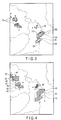
- FIG. 3 is a diagram showing an example of a recognition image produced by the computer 14.
- FIG. 4 is a diagram showing a binarized image.
- the computer 14 executes recognition processing of all rain areas and a heavy rain area by using digital data from the signal processing unit 13 (S1). Specifically, the computer 14 produces observation data including rainfall intensity data based on the digital data (data including reception intensity). The computer 14 produces an observation image to indicating a rain area based on the observation data. The observation image t0 is based on the observation data at time t0. To the produced observation image, the computer 14 performs recognition processing of all rain areas and the heavy rain area including binarization processing, extracting processing of a circumscribed rectangle (circumcircle), extracting processing of coordinate point information, and labeling processing.
- recognition processing of all rain areas and the heavy rain area including binarization processing, extracting processing of a circumscribed rectangle (circumcircle), extracting processing of coordinate point information, and labeling processing.
- the computer 14 executes processing such as distance measurement to measure a distance between respective rain areas 30, area measurement to measure an area of each rain area 30, calculation of an average rainfall intensity of each rain area 30, and calculation of an indexed size of each rain area 30 (S2).
- the computer 14 stores the measurement results and calculation results in the storage 15.
- the computer 14 executes the above processing (S1, S2) at intervals of ⁇ t (e.g., two minutes) from time to to tn so as to produce recognition images of all rain areas and the heavy rain area from the results of recognition processing (S3).
- FIG. 3 shows an example of a recognition image indicating all rain areas 30 obtained through the recognition processing of the computer 14. As shown in FIG. 3 , all rain areas 30 are labeled A to F by labeling processing on the map produced through the extracting processing of coordinate point (longitude and latitude) information.
- levels of the rainfall intensity in each of all rain areas 30 in the recognition image are distinguished from each other by areas on the basis of the rainfall intensity data; however, it is also possible to distinguish the levels using colors for display. For example, in the rain area 30 labeled F, a portion 100 with a maximum rainfall intensity is displayed in orange, a portion 110 with an intermediate rainfall intensity is displayed in yellow, a portion 120 with a relatively small rainfall intensity is displayed in blue, and a portion 130 with a minimum rainfall intensity is displayed in green.
- FIG. 4 shows an example of a recognition image indicating all rain areas 40 to which the binarization processing and the extracting processing of a circumscribed rectangle (circumcircle) are performed.
- each of all rain areas 40 that are binarized can be extracted for each of the labels A to F by extracting processing of a circumscribed rectangle 41.
- the computer 14 can store a recognition image extracted for each of the labels A to F in the storage 15 along with the coordinate point information including a centroid 42.
- FIG. 5 shows an example of a recognition image indicating heavy rain areas 50.
- the heavy rain areas 50 are labeled a to f by labeling processing on the map produced by the extracting processing of coordinate point (longitude and latitude) information.
- FIG. 6 shows an example of a recognition image indicating heavy rain areas 60 to which the binarization processing and the extracting processing of a circumscribed rectangle (circumcircle) are performed.
- each of the binarized heavy rain areas 60 can be extracted for each of the labels a to f by extracting processing of a circumscribed rectangle 61.
- the computer 14 can store a recognition image extracted for each of the labels a to f in the storage 15 along with the coordinate point information including the centroid 62.
- the computer 14 can distribute the recognition images 30, 40, 50, and 60 of all rain areas and heavy rain areas stored in the storage 15 from the communication device 16 to a server, etc. of a weather center via the network. Thereby, the server can display each recognition image on a screen of a display device.
- the computer 14 executes tracking processing of the heavy rain areas and identification processing of a situation change by using the recognition images produced through the recognition processing executed at intervals of a time period ⁇ t (S4). Specifically, the computer 14 executes segmentation processing, matching processing of positions, coordinate evaluation processing, abnormal value determination processing of a displacement amount (determination processing of an error image), tracking processing, identification processing of a situation change, and re-labeling processing. In other words, the computer 14 separates a recognition image as a processing target from each of the recognition images 50 and 60 of heavy rain areas by segmentation processing. The computer 14 identifies temporal transition of the image as a processing target by the matching processing of positions and the coordinate evaluation processing. Moreover, the computer 14 identifies a situation change of the heavy rain area as a processing target by the tracking processing of the recognition image as a processing target and identification processing of a situation change.
- FIGS. 7 to 9 are diagrams respectively showing processing results obtained by the tracking processing of the heavy rain area and the identification processing of a situation change.
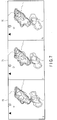
- FIG. 7 indicates recognition images 70, 71, and 72 indicating temporal variation at time t0, t-1, and t-2 in the heavy rain area labeled as d shown in FIG. 5 , for example.
- FIG. 8 shows recognition images 80, 81, and 82 indicating temporal variation at time t0, t-1, and t-2 in the heavy rain areas to which the binarization processing and the extracting processing of a circumscribed rectangle (circumcircle) are performed.
- the computer 14 extracts information on a situation change of the heavy rain areas by executing comparative processing of a recognition image at time t0 and an earlier recognition image processed time ⁇ t (a recognition image at time t-1), for example.
- FIG. 9 shows a diagram in which images of the heavy rain area indicating temporal variation through time t0, t-1, and t-2 in each frame are superimposed, which is information on a situation change of the heavy rain area.
- the computer 14 executes the processing of generating threat information (S5) by using results of the above processing: the recognition processing of rain areas and heavy rain areas (S1); measurement processing and calculation processing regarding the rain areas (S2); processing of producing recognition images of the rain areas and heavy rain areas (S3); and identification processing of a situation change of the rain areas (S4).
- the threat information and generating processing will be described with reference to FIG. 10 .
- the threat information in the present embodiment is information for calculating (estimating) a degree of threat (degree of hazard) to a target point caused by severe rain.
- the degree of threat may be defined as an evaluation value which can be calculated by an evaluation function f (a ⁇ D, b ⁇ A, c ⁇ Sc, d ⁇ GD).
- a, b, c, and d indicate weight coefficients.
- the threat information corresponds to parameters D, A, Sc, and GD of the evaluation function f, for example.
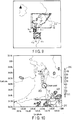
- FIG. 10 is a diagram for explaining threat information D, A, Sc, and GD.
- the parameter D indicates a distance (meters) to a target point 200 specified by a longitude and a latitude from the centroid of a circumscribed rectangle 220 of a heavy rain area with rainfall intensity equal to or larger than 50 mm/h in a rain area 210.
- the rainfall intensities in the rain area 210 are distinguished from each other by area, as shown in FIG. 3 .
- Rainfall intensities may be distinguished from each other by color for display by an indicator 230.
- the parameter Sc indicates a size of the rain area, and is defined by a number of pixels of the recognition image.
- the parameter GD growth and decay indicates a growth-and-decay state of the rain area, and may be defined as a difference in number of pixels of the heavy rain area at time t and time t - ⁇ t, for example.
- the computer 14 specifies a degree of threat as an evaluation value which can be calculated by the evaluation function f, and generates parameters D, A, Sc, and GD of the evaluation function f as threat information.
- the computer 14 calculates (estimates) a degree of threat (degree of hazard) to the target point caused by severe rain by applying the generated threat information to the evaluation function f.
- the computer 14 stores, in the storage 15, the generated threat information and the degree of threat (degree of hazard) calculated (estimated) by applying the threat information to the evaluation function f.
- the computer 14 distributes the threat information and the degree of threat (degree of hazard) stored in the storage 15 from the communication device 16 to a server, etc. of a weather center, for example, via the network (S6).
- the server can display the threat information and the degree of threat on the screen of the display device.
- the degree of threat may be calculated (estimated) by causing the computer 14 to execute processing to distribute the threat information to the server of the weather center, and applying the threat information to the evaluation function f at the server.
- a degree of threat caused by severe rain is calculated for one target point 200 is explained; however, the configuration is not limited thereto, and it is possible to calculate a degree of threat caused by severe rain for a plurality of target points.
- the computer 14 executes software (algorithm) shown in FIG. 2 , thereby processing the weather radar data, generating a recognition image of a rain area, calculating an area, rainfall intensity, and a size of the rain area, and extracting information on a situation change of the rain area.
- software algorithm shown in FIG. 2 , thereby processing the weather radar data, generating a recognition image of a rain area, calculating an area, rainfall intensity, and a size of the rain area, and extracting information on a situation change of the rain area.
- it is possible to particularly generate a recognition image of a heavy rain area that leads to severe rain calculate an area, rainfall intensity, and a size of the heavy rain area, and extract information on a situation change of the heavy rain area.
- the computer 14 generates threat information for calculating (estimating) a degree of threat (degree of hazard) to a target point caused by severe rain (heavy rainfall).
- the threat information is information indicating a distance from the heavy rain area to the target point, a state of approaching the target area of the heavy rain area, a size of the heavy rain area, and a growth-and-decay state of the heavy rain area. Since the threat information can be generated according to the present embodiment, it is possible to apply the threat information as a parameter, and define the evaluation function f for calculating the degree of threat (evaluation value).
- the computer 14 may calculate a degree of threat (evaluation value) for the target point by applying the threat information as a parameter to a preliminarily prepared evaluation function f. Furthermore, if the evaluation function f is preliminarily prepared, the server of the weather center can calculate (estimate) a degree of threat (degree of hazard) by applying the threat information distributed from the computer 14 as a parameter.
- the server of the weather center can identify a degree of threat (degree of hazard) to the target point caused by the severe rain, and thus can realize an effective weather forecast for avoiding a disaster due to severe rain that is a specific and local weather phenomenon.
Landscapes
- Engineering & Computer Science (AREA)
- Radar, Positioning & Navigation (AREA)
- Remote Sensing (AREA)
- Physics & Mathematics (AREA)
- Computer Networks & Wireless Communication (AREA)
- General Physics & Mathematics (AREA)
- Electromagnetism (AREA)
- Environmental & Geological Engineering (AREA)
- Life Sciences & Earth Sciences (AREA)
- Atmospheric Sciences (AREA)
- Biodiversity & Conservation Biology (AREA)
- Ecology (AREA)
- Environmental Sciences (AREA)
- Radar Systems Or Details Thereof (AREA)
Abstract
Description
- Embodiments described herein relate generally to a weather radar apparatus capable of implementing a severe rain prediction function and a severe rain prediction method.
- In recent years, local severe rain known as "guerrilla rainstorms," which are a sudden and specific weather phenomenon, have frequently occurred. In order to minimize the disaster resulting from such severe rain, it is increasingly necessary to estimate a degree of threat due to the severe rain by performing severe rain prediction to predict and analyze occurrences of severe rain. To implement such a function, a severe rain prediction system using a high-resolution weather radar, etc. is proposed.
- Patent literature 1: Jpn. Pat. Appln. KOKAI Publication No.
2001-289961 - The conventional severe rain prediction system has a configuration to perform processing of referring to previous cases similar to the current rain area, thereby predicting and analyzing occurrences of severe rain so as to determine a degree of hazard based on the prediction result. Since such a severe rain prediction system depends on the previous cases, it is difficult for the system to accurately and rapidly predict and analyze severe rain that is a specific and local weather phenomenon. It is also difficult to determine an effective degree of hazard based on the prediction result so as to minimize the disaster resulting from severe rain.
- Accordingly, the objective is to provide a weather radar apparatus capable of accurately and rapidly predicting and analyzing severe rain which is a specific and local weather phenomenon, and estimating an effective degree of threat based on the prediction result.
- The weather radar apparatus of the present embodiment has a configuration including means for processing a radar signal received by an antenna so as to generate observation data related to a weather phenomenon, and information processing means for processing the observation data. The information processing means includes means for executing recognition processing of recognizing a rain area that has arisen as the weather phenomenon on the basis of the observation data, and means for generating threat information for calculating a degree of threat of severe rain to a target point on the basis of the recognition result of the recognition processing.
-
-
FIG. 1 is a block diagram explaining a configuration of a weather radar apparatus according to an embodiment. -
FIG. 2 is a flow chart explaining operation of the weather radar apparatus according to the embodiment. -
FIG. 3 is a diagram showing an example of a recognition image of all rain areas according to the embodiment. -
FIG. 4 is a diagram showing an example of a binarized image of all the rain areas according to the embodiment. -
FIG. 5 is a diagram showing an example of a recognition image of a heavy rain area according to the embodiment. -
FIG. 6 is a diagram showing an example of a binarized image of the heavy rain area according to the embodiment. -
FIG. 7 is a diagram showing an example of a recognition image indicating temporal variation of the heavy rain area according to the embodiment. -
FIG. 8 is a diagram showing an example of a binarized image indicating temporal variation of the heavy rain area according to the embodiment. -
FIG. 9 is a diagram in which images of the heavy rain area indicating temporal variation are superimposed according to the embodiment. -
FIG. 10 is a diagram for explaining threat information according to the embodiment. - Hereinafter, an embodiment will be described with reference to the drawings.
-
FIG. 1 is a block diagram explaining a configuration of aweather radar apparatus 1 according to the present embodiment. In a configuration of aweather radar apparatus 1 of the present embodiment, a high-resolution weather radar such as a phased-array weather radar, or a weather radar with an XRAIN (eXtended RAdar Information Network) system is applied. - As shown in
FIG. 1 , theweather radar apparatus 1 has anantenna unit 10, a radarsignal processing device 11, acomputer 14, astorage 15, and acommunication device 16. Theantenna unit 10 includes a phased array antenna, for example, receives reflected waves of transmitted electric waves, and transmits the reflected waves to the radarsignal processing device 11. - The radar
signal processing device 11 includes an A/D converter 12 and asignal processing unit 13. The A/D converter 12 converts analog signals, which are reflected waves received by theantenna unit 10, into digital signals. Thesignal processing unit 13 executes various digital signal processing such as processing of removing ground clutter, and outputs digital data after the signal processing to thecomputer 14. - The
computer 14 inputs the digital data from thesignal processing unit 13 and performs data processing and analysis processing related to the severe rain prediction processing of the present embodiment, by using software stored in thestorage 15. As will be described, the severe rain prediction processing of the present embodiment includes processing of generating threat information for calculating (estimating) a degree of threat to a target point. Thestorage 15 stores data and information necessary for data processing and analysis processing, in addition to the software executed by thecomputer 14. Thecommunication device 16 is connected to the network and controlled by thecomputer 14 so as to distribute data and information output by the data processing and the analysis processing to a server, etc. of a weather center, for example. -
FIG. 2 is a flowchart showing the processing executed by thecomputer 14.FIG. 3 is a diagram showing an example of a recognition image produced by thecomputer 14.FIG. 4 is a diagram showing a binarized image. - As shown in
FIG. 2 , thecomputer 14 executes recognition processing of all rain areas and a heavy rain area by using digital data from the signal processing unit 13 (S1). Specifically, thecomputer 14 produces observation data including rainfall intensity data based on the digital data (data including reception intensity). Thecomputer 14 produces an observation image to indicating a rain area based on the observation data. The observation image t0 is based on the observation data at time t0. To the produced observation image, thecomputer 14 performs recognition processing of all rain areas and the heavy rain area including binarization processing, extracting processing of a circumscribed rectangle (circumcircle), extracting processing of coordinate point information, and labeling processing. - Next, the
computer 14 executes processing such as distance measurement to measure a distance betweenrespective rain areas 30, area measurement to measure an area of eachrain area 30, calculation of an average rainfall intensity of eachrain area 30, and calculation of an indexed size of each rain area 30 (S2). Thecomputer 14 stores the measurement results and calculation results in thestorage 15. - The
computer 14 executes the above processing (S1, S2) at intervals of Δt (e.g., two minutes) from time to to tn so as to produce recognition images of all rain areas and the heavy rain area from the results of recognition processing (S3).FIG. 3 shows an example of a recognition image indicating allrain areas 30 obtained through the recognition processing of thecomputer 14. As shown inFIG. 3 , allrain areas 30 are labeled A to F by labeling processing on the map produced through the extracting processing of coordinate point (longitude and latitude) information. - Herein, for descriptive purposes, levels of the rainfall intensity in each of all
rain areas 30 in the recognition image are distinguished from each other by areas on the basis of the rainfall intensity data; however, it is also possible to distinguish the levels using colors for display. For example, in therain area 30 labeled F, aportion 100 with a maximum rainfall intensity is displayed in orange, aportion 110 with an intermediate rainfall intensity is displayed in yellow, aportion 120 with a relatively small rainfall intensity is displayed in blue, and aportion 130 with a minimum rainfall intensity is displayed in green. -
FIG. 4 shows an example of a recognition image indicating allrain areas 40 to which the binarization processing and the extracting processing of a circumscribed rectangle (circumcircle) are performed. As shown inFIG. 4 , each of allrain areas 40 that are binarized can be extracted for each of the labels A to F by extracting processing of acircumscribed rectangle 41. Thecomputer 14 can store a recognition image extracted for each of the labels A to F in thestorage 15 along with the coordinate point information including a centroid 42. -
FIG. 5 shows an example of a recognition image indicatingheavy rain areas 50. As shown inFIG. 5 , theheavy rain areas 50 are labeled a to f by labeling processing on the map produced by the extracting processing of coordinate point (longitude and latitude) information. -
FIG. 6 shows an example of a recognition image indicatingheavy rain areas 60 to which the binarization processing and the extracting processing of a circumscribed rectangle (circumcircle) are performed. As shown inFIG. 6 , each of the binarizedheavy rain areas 60 can be extracted for each of the labels a to f by extracting processing of a circumscribedrectangle 61. Thecomputer 14 can store a recognition image extracted for each of the labels a to f in thestorage 15 along with the coordinate point information including thecentroid 62. - The
computer 14 can distribute therecognition images storage 15 from thecommunication device 16 to a server, etc. of a weather center via the network. Thereby, the server can display each recognition image on a screen of a display device. - Next, the
computer 14 executes tracking processing of the heavy rain areas and identification processing of a situation change by using the recognition images produced through the recognition processing executed at intervals of a time period Δt (S4). Specifically, thecomputer 14 executes segmentation processing, matching processing of positions, coordinate evaluation processing, abnormal value determination processing of a displacement amount (determination processing of an error image), tracking processing, identification processing of a situation change, and re-labeling processing. In other words, thecomputer 14 separates a recognition image as a processing target from each of therecognition images computer 14 identifies temporal transition of the image as a processing target by the matching processing of positions and the coordinate evaluation processing. Moreover, thecomputer 14 identifies a situation change of the heavy rain area as a processing target by the tracking processing of the recognition image as a processing target and identification processing of a situation change. -
FIGS. 7 to 9 are diagrams respectively showing processing results obtained by the tracking processing of the heavy rain area and the identification processing of a situation change.FIG. 7 indicatesrecognition images FIG. 5 , for example.FIG. 8 showsrecognition images - As the identification processing of a situation change, the
computer 14 extracts information on a situation change of the heavy rain areas by executing comparative processing of a recognition image at time t0 and an earlier recognition image processed time Δt (a recognition image at time t-1), for example.FIG. 9 shows a diagram in which images of the heavy rain area indicating temporal variation through time t0, t-1, and t-2 in each frame are superimposed, which is information on a situation change of the heavy rain area. - Referring back to
FIG. 2 , thecomputer 14 executes the processing of generating threat information (S5) by using results of the above processing: the recognition processing of rain areas and heavy rain areas (S1); measurement processing and calculation processing regarding the rain areas (S2); processing of producing recognition images of the rain areas and heavy rain areas (S3); and identification processing of a situation change of the rain areas (S4). Hereinafter, the threat information and generating processing will be described with reference toFIG. 10 . - The threat information in the present embodiment is information for calculating (estimating) a degree of threat (degree of hazard) to a target point caused by severe rain. The degree of threat may be defined as an evaluation value which can be calculated by an evaluation function f (a·D, b·A, c·Sc, d·GD). Herein, a, b, c, and d indicate weight coefficients. The threat information corresponds to parameters D, A, Sc, and GD of the evaluation function f, for example.
-
FIG. 10 is a diagram for explaining threat information D, A, Sc, and GD. As shown inFIG. 10 , the parameter D (distance) indicates a distance (meters) to atarget point 200 specified by a longitude and a latitude from the centroid of a circumscribedrectangle 220 of a heavy rain area with rainfall intensity equal to or larger than 50 mm/h in arain area 210. Herein, for descriptive purposes, the rainfall intensities in therain area 210 are distinguished from each other by area, as shown inFIG. 3 . Rainfall intensities may be distinguished from each other by color for display by anindicator 230. - The parameter A (access) indicates a state of approaching the target point. Specifically, in accordance with the difference of the distance D between time t and t - Δt, if a condition of "D(t) - D(t - Δt) < 0" is statisfied, the parameter is indexed as "approaching (+1)." If a condition of "D(t) - D(t - Δt) = 0" is satisfied, the parameter is indexed as "stationary (±0)." If a condition of "D(t) - D(t - Δt) > 0" is satisfied, the parameter is indexed as "leaving (-1)." Alternatively, for example, approximation can be specified when a cumulative value, etc. over ten minutes exceeds a certain threshold value.
- The parameter Sc (scale) indicates a size of the rain area, and is defined by a number of pixels of the recognition image. The parameter GD (growth and decay) indicates a growth-and-decay state of the rain area, and may be defined as a difference in number of pixels of the heavy rain area at time t and time t - Δt, for example.
- The
computer 14 specifies a degree of threat as an evaluation value which can be calculated by the evaluation function f, and generates parameters D, A, Sc, and GD of the evaluation function f as threat information. Thecomputer 14 calculates (estimates) a degree of threat (degree of hazard) to the target point caused by severe rain by applying the generated threat information to the evaluation function f. Thecomputer 14 stores, in thestorage 15, the generated threat information and the degree of threat (degree of hazard) calculated (estimated) by applying the threat information to the evaluation function f. - Moreover, the
computer 14 distributes the threat information and the degree of threat (degree of hazard) stored in thestorage 15 from thecommunication device 16 to a server, etc. of a weather center, for example, via the network (S6). Thereby, the server can display the threat information and the degree of threat on the screen of the display device. - In the present embodiment, the degree of threat (degree of hazard) may be calculated (estimated) by causing the
computer 14 to execute processing to distribute the threat information to the server of the weather center, and applying the threat information to the evaluation function f at the server. In the present embodiment, a case where a degree of threat caused by severe rain is calculated for onetarget point 200 is explained; however, the configuration is not limited thereto, and it is possible to calculate a degree of threat caused by severe rain for a plurality of target points. - As described above, according to the present embodiment, the
computer 14 executes software (algorithm) shown inFIG. 2 , thereby processing the weather radar data, generating a recognition image of a rain area, calculating an area, rainfall intensity, and a size of the rain area, and extracting information on a situation change of the rain area. In this case, it is possible to particularly generate a recognition image of a heavy rain area that leads to severe rain, calculate an area, rainfall intensity, and a size of the heavy rain area, and extract information on a situation change of the heavy rain area. - Furthermore, the
computer 14 generates threat information for calculating (estimating) a degree of threat (degree of hazard) to a target point caused by severe rain (heavy rainfall). The threat information is information indicating a distance from the heavy rain area to the target point, a state of approaching the target area of the heavy rain area, a size of the heavy rain area, and a growth-and-decay state of the heavy rain area. Since the threat information can be generated according to the present embodiment, it is possible to apply the threat information as a parameter, and define the evaluation function f for calculating the degree of threat (evaluation value). - In the present embodiment, the
computer 14 may calculate a degree of threat (evaluation value) for the target point by applying the threat information as a parameter to a preliminarily prepared evaluation function f. Furthermore, if the evaluation function f is preliminarily prepared, the server of the weather center can calculate (estimate) a degree of threat (degree of hazard) by applying the threat information distributed from thecomputer 14 as a parameter. - In conclusion, according to the present embodiment, it is possible to accurately and rapidly predict and analyze severe rain that is a specific and local weather phenomenon. Since information on the threat on the target point caused by severe rain can be generated, it is possible to calculate (estimate) a degree of threat (degree of hazard) which is effective for minimizing a disaster by using the threat information. Accordingly, the server of the weather center, for example, can identify a degree of threat (degree of hazard) to the target point caused by the severe rain, and thus can realize an effective weather forecast for avoiding a disaster due to severe rain that is a specific and local weather phenomenon.
- While certain embodiments have been described, these embodiments have been presented by way of example only, and are not intended to limit the scope of the inventions. Indeed, the novel embodiments described herein may be embodied in a variety of other forms; furthermore, various omissions, substitutions and changes in the form of the embodiments described herein may be made without departing from the spirit of the invention. The accompanying claims and their equivalents are intended to cover such forms or modifications as would fall within the scope and spirit of the invention.
Claims (9)
- A weather radar apparatus comprising:means for generating observation data related to a weather phenomenon by processing a radar signal received by an antenna; andinformation processing means for processing the observation data,the information processing means including:means for executing recognition processing to recognize a rain area which arises as the weather phenomenon, based on the observation data; andmeans for generating threat information for calculating a degree of threat of severe rain to a target point, based on a recognition result of the recognition processing.
- The weather radar apparatus according to claim 1, wherein the information processing means includes means for specifying a predetermined function for calculating the degree of threat, applying the threat information as a parameter to the function, and calculating the degree of threat.
- The weather radar apparatus according to claim 1 or 2, wherein the information processing means includes:means for executing identification processing to identify a situation change of a rain area, based on the recognition result of the recognition processing; andmeans for generating the threat information, based on the recognition result of the recognition processing and an identification result of the identification processing.
- The weather radar apparatus according to any one of claims 1 to 3, including communication means for distributing the threat information generated by the information processing means.
- The weather radar apparatus according to any one of claims 1, 3, and 4, wherein the information processing means includes:means for specifying a predetermined function for calculating the degree of threat, applying the threat information as a parameter to the function, and calculating the degree of threat; andmeans for calculating, as the threat information, a distance from a rain area of the severe rain to the target point, indexed data indicating a state of the rain area approaching the target point, data indicating a size of the rain area, and a growth-and-decay state of the rain area.
- A severe rain prediction method to be applied to a weather radar apparatus that includes:means for generating observation data related to a weather phenomenon by processing a radar signal received by an antenna; andinformation processing means for processing the observation data,the information processing means performing:processing of recognizing a rain area which arises as the weather phenomenon, based on the observation data; andprocessing of generating threat information for calculating a degree of threat of severe rain to a target point, based on a processing result of the processing of recognizing.
- The severe rain prediction method according to claim 6, including processing of specifying a predetermined function for calculating the degree of threat, applying the threat information as a parameter to the function, and calculating the degree of threat, by the information processing means.
- The severe rain prediction method according to claim 6 or 7, wherein the information processing means performs:processing of identifying a situation change of the rain area, based on the processing result of the processing of recognizing; andprocessing of generating the threat information, based on the processing result of the processing of recognizing and a processing result of the processing of identifying.
- The severe rain prediction method according to claim 6 or 8, wherein the information processing means performs:processing of specifying a predetermined function for calculating the degree of threat, applying the threat information as a parameter to the function, and calculating the degree of threat; andprocessing of calculating, as the threat information, a distance from a rain area of the severe rain to the target point, indexed data indicating a state of the rain area approaching the target point, data indicating a size of the rain area, and a growth-and-decay state of the rain area.
Applications Claiming Priority (2)
| Application Number | Priority Date | Filing Date | Title |
|---|---|---|---|
| JP2018039062A JP6689304B2 (en) | 2018-03-05 | 2018-03-05 | Meteorological radar device and heavy rain forecasting method |
| PCT/JP2018/034037 WO2019171634A1 (en) | 2018-03-05 | 2018-09-13 | Weather radar device and heavy rain prediction method |
Publications (2)
| Publication Number | Publication Date |
|---|---|
| EP3764130A1 true EP3764130A1 (en) | 2021-01-13 |
| EP3764130A4 EP3764130A4 (en) | 2021-12-01 |
Family
ID=67847013
Family Applications (1)
| Application Number | Title | Priority Date | Filing Date |
|---|---|---|---|
| EP18908345.4A Withdrawn EP3764130A4 (en) | 2018-03-05 | 2018-09-13 | WEATHER RADAR DEVICE AND HEAVY RAIN PREDICTION METHOD |
Country Status (7)
| Country | Link |
|---|---|
| US (1) | US11300681B2 (en) |
| EP (1) | EP3764130A4 (en) |
| JP (1) | JP6689304B2 (en) |
| CN (1) | CN111095033B (en) |
| MY (1) | MY200836A (en) |
| TW (1) | TWI676815B (en) |
| WO (1) | WO2019171634A1 (en) |
Families Citing this family (4)
| Publication number | Priority date | Publication date | Assignee | Title |
|---|---|---|---|---|
| DE102022108428A1 (en) * | 2022-04-07 | 2023-10-12 | Infineon Technologies Ag | RADAR DEVICE WITH COMPENSATION OF NON-LINEARITIES |
| CN114814991A (en) * | 2022-06-28 | 2022-07-29 | 成都信息工程大学 | Method and device for identifying spatial distribution area of meteorological element field |
| JP2024016560A (en) * | 2022-07-26 | 2024-02-07 | 株式会社東芝 | Radar system, data transfer device and method |
| CN116012618A (en) * | 2022-12-02 | 2023-04-25 | 广东方柚科技有限公司 | A weather identification method, system, equipment and medium based on radar echo chart |
Family Cites Families (25)
| Publication number | Priority date | Publication date | Assignee | Title |
|---|---|---|---|---|
| US6128578A (en) | 1996-12-26 | 2000-10-03 | Nippon Telegraph And Telephone Corporation | Meteorological radar precipitation pattern prediction method and apparatus |
| JP3375038B2 (en) * | 1997-04-16 | 2003-02-10 | 日本電信電話株式会社 | Precipitation pattern change prediction method and apparatus |
| JP3377075B2 (en) * | 1997-02-13 | 2003-02-17 | 日本電信電話株式会社 | 2D precipitation forecasting device |
| JP3764287B2 (en) * | 1998-12-21 | 2006-04-05 | 富士電機ホールディングス株式会社 | Rainfall prediction correction method, apparatus thereof, and recording medium |
| JP2001289961A (en) * | 2000-04-06 | 2001-10-19 | Mitsubishi Electric Corp | Heavy rain forecast system |
| JP2002107462A (en) * | 2000-09-28 | 2002-04-10 | Foundation Of River & Basin Integrated Communications Japan | Rainfall food forecasting system |
| US6670908B2 (en) * | 2001-07-31 | 2003-12-30 | Baron Services, Inc. | Automated system and method for processing meteorological data |
| JP4095528B2 (en) | 2003-09-30 | 2008-06-04 | 三菱電機株式会社 | Rainfall movement prediction apparatus and rainfall movement prediction method |
| US7084775B1 (en) * | 2004-07-12 | 2006-08-01 | User-Centric Ip, L.P. | Method and system for generating and sending user-centric weather alerts |
| JP2006252128A (en) | 2005-03-10 | 2006-09-21 | Shimizu Corp | Slope failure prediction and evacuation information transmission system to surrounding area |
| US8730086B2 (en) * | 2008-08-26 | 2014-05-20 | Viasat, Inc. | Weather detection using satellite communication signals |
| US7982658B2 (en) * | 2009-03-31 | 2011-07-19 | Honeywell International Inc. | Systems and methods for assessing weather in proximity to an airborne aircraft |
| JP2010286458A (en) * | 2009-06-15 | 2010-12-24 | Chugoku Electric Power Co Inc:The | Concentrated heavy rainfall prediction system |
| JP5973124B2 (en) | 2010-06-09 | 2016-08-23 | 株式会社安藤・間 | Sudden local heavy rain prediction method and apparatus |
| CN102279389B (en) * | 2010-06-11 | 2014-05-14 | 株式会社东芝 | Radar return signal processing apparatus and method |
| WO2014020995A1 (en) * | 2012-07-31 | 2014-02-06 | 古野電気株式会社 | Meteorological information display system, human navigation device, meteorological information display program and meteorological information display method |
| US20140372038A1 (en) * | 2013-04-04 | 2014-12-18 | Sky Motion Research, Ulc | Method for generating and displaying a nowcast in selectable time increments |
| JP2015099034A (en) | 2013-11-18 | 2015-05-28 | 国立研究開発法人宇宙航空研究開発機構 | Observation information processing apparatus, observation information processing method, and observation information processing program |
| US10288769B2 (en) * | 2014-05-28 | 2019-05-14 | Metroweather Co., Ltd. | Weather forecasting system |
| JP2017003416A (en) * | 2015-06-10 | 2017-01-05 | 古野電気株式会社 | Precipitation prediction system |
| JP2019045146A (en) * | 2016-01-12 | 2019-03-22 | 株式会社東芝 | Weather forecasting device, weather forecasting method, and weather forecasting program |
| KR101755521B1 (en) * | 2016-01-19 | 2017-07-26 | 홍익대학교 산학협력단 | Apparatus and method for measuring areal rainfall using radar polygon method |
| WO2017126171A1 (en) * | 2016-01-22 | 2017-07-27 | 株式会社 東芝 | Weather phenomenon occurrence possibility determination system and method |
| CN105842756B (en) * | 2016-03-30 | 2018-09-14 | 广州积雨云科技有限公司 | A kind of thunderstorm information prediction method |
| CN107656256B (en) * | 2017-11-02 | 2019-06-28 | 广州积雨云科技有限公司 | Utilize the method for radar data recognition and tracking heavy rain |
-
2018
- 2018-03-05 JP JP2018039062A patent/JP6689304B2/en active Active
- 2018-09-13 EP EP18908345.4A patent/EP3764130A4/en not_active Withdrawn
- 2018-09-13 WO PCT/JP2018/034037 patent/WO2019171634A1/en not_active Ceased
- 2018-09-13 CN CN201880055817.5A patent/CN111095033B/en active Active
- 2018-09-13 MY MYPI2020001259A patent/MY200836A/en unknown
- 2018-09-18 TW TW107132748A patent/TWI676815B/en active
-
2020
- 2020-03-09 US US16/812,527 patent/US11300681B2/en active Active
Also Published As
| Publication number | Publication date |
|---|---|
| US11300681B2 (en) | 2022-04-12 |
| JP6689304B2 (en) | 2020-04-28 |
| TW201939068A (en) | 2019-10-01 |
| TWI676815B (en) | 2019-11-11 |
| JP2019152582A (en) | 2019-09-12 |
| CN111095033A (en) | 2020-05-01 |
| MY200836A (en) | 2024-01-17 |
| WO2019171634A1 (en) | 2019-09-12 |
| EP3764130A4 (en) | 2021-12-01 |
| CN111095033B (en) | 2022-08-30 |
| US20200209386A1 (en) | 2020-07-02 |
Similar Documents
| Publication | Publication Date | Title |
|---|---|---|
| US11300681B2 (en) | Weather radar apparatus and severe rain prediction method | |
| US8138960B2 (en) | Map information update support device, map information update support method and computer readable recording medium | |
| Brusch et al. | Ship surveillance with TerraSAR-X | |
| US8818029B1 (en) | Weather forecasting systems and methods | |
| US6920233B2 (en) | Method and apparatus for short-term prediction of convective weather | |
| US20180286052A1 (en) | Object motion mapping using panchromatic and multispectral imagery from single pass electro-optical satellite imaging sensors | |
| US11754704B2 (en) | Synthetic-aperture-radar image processing device and image processing method | |
| Piñeros et al. | Detecting tropical cyclone genesis from remotely sensed infrared image data | |
| Zou et al. | A method of radar echo extrapolation based on TREC and Barnes filter | |
| US20240427012A1 (en) | Sinkage prediction device and sinkage prediction method | |
| CN117930390A (en) | Thunderstorm detection method, detection result evaluation method, device and equipment | |
| CN121008337A (en) | A method for rainstorm early warning based on dynamic fusion of multi-source forecast products | |
| CN107369163B (en) | Rapid SAR image target detection method based on optimal entropy dual-threshold segmentation | |
| Shi et al. | Sea ice thickness retrieval from SAR imagery over Bohai sea | |
| US11835619B2 (en) | Synthetic aperture radar signal analysis device, synthetic aperture radar signal analysis method, and synthetic aperture radar signal analysis program | |
| Uzkent et al. | Spectral validation of measurements in a vehicle tracking DDDAS | |
| JP4266858B2 (en) | Local heavy rain monitoring system | |
| RU2596610C1 (en) | Method of search and detection of object | |
| US11460573B2 (en) | Synthetic aperture radar signal processing device and method | |
| CN116563348B (en) | Infrared weak small target multi-mode tracking method and system based on dual-feature template | |
| JP7127927B1 (en) | Water vapor observation method | |
| JP7127928B1 (en) | Water vapor observation method | |
| CN107808393B (en) | Target tracking method with anti-interference performance in intelligent video monitoring field | |
| CN114445717B (en) | Remote sensing image processing method and system for land resource management | |
| JP2017067597A (en) | River information system and detection method |
Legal Events
| Date | Code | Title | Description |
|---|---|---|---|
| STAA | Information on the status of an ep patent application or granted ep patent |
Free format text: STATUS: THE INTERNATIONAL PUBLICATION HAS BEEN MADE |
|
| PUAI | Public reference made under article 153(3) epc to a published international application that has entered the european phase |
Free format text: ORIGINAL CODE: 0009012 |
|
| STAA | Information on the status of an ep patent application or granted ep patent |
Free format text: STATUS: REQUEST FOR EXAMINATION WAS MADE |
|
| 17P | Request for examination filed |
Effective date: 20200305 |
|
| AK | Designated contracting states |
Kind code of ref document: A1 Designated state(s): AL AT BE BG CH CY CZ DE DK EE ES FI FR GB GR HR HU IE IS IT LI LT LU LV MC MK MT NL NO PL PT RO RS SE SI SK SM TR |
|
| AX | Request for extension of the european patent |
Extension state: BA ME |
|
| DAV | Request for validation of the european patent (deleted) | ||
| DAX | Request for extension of the european patent (deleted) | ||
| A4 | Supplementary search report drawn up and despatched |
Effective date: 20211103 |
|
| RIC1 | Information provided on ipc code assigned before grant |
Ipc: G01S 7/41 20060101ALI20211027BHEP Ipc: G01S 7/00 20060101ALI20211027BHEP Ipc: G01S 13/95 20060101ALI20211027BHEP Ipc: G01W 1/10 20060101AFI20211027BHEP |
|
| STAA | Information on the status of an ep patent application or granted ep patent |
Free format text: STATUS: EXAMINATION IS IN PROGRESS |
|
| 17Q | First examination report despatched |
Effective date: 20230323 |
|
| RAP1 | Party data changed (applicant data changed or rights of an application transferred) |
Owner name: KABUSHIKI KAISHA TOSHIBA |
|
| STAA | Information on the status of an ep patent application or granted ep patent |
Free format text: STATUS: THE APPLICATION HAS BEEN WITHDRAWN |
|
| 18W | Application withdrawn |
Effective date: 20260320 |