EP3764082A1 - Apparatus and method for identifying a refrigerant fluid contained in a tank or in a measuring cell of a system for recharging an air-conditioning plant - Google Patents
Apparatus and method for identifying a refrigerant fluid contained in a tank or in a measuring cell of a system for recharging an air-conditioning plant Download PDFInfo
- Publication number
- EP3764082A1 EP3764082A1 EP20183634.3A EP20183634A EP3764082A1 EP 3764082 A1 EP3764082 A1 EP 3764082A1 EP 20183634 A EP20183634 A EP 20183634A EP 3764082 A1 EP3764082 A1 EP 3764082A1
- Authority
- EP
- European Patent Office
- Prior art keywords
- refrigerant fluid
- intensity
- sub
- wavelength
- photodetector
- Prior art date
- Legal status (The legal status is an assumption and is not a legal conclusion. Google has not performed a legal analysis and makes no representation as to the accuracy of the status listed.)
- Withdrawn
Links
- 239000012530 fluid Substances 0.000 title claims abstract description 48
- 239000003507 refrigerant Substances 0.000 title claims abstract description 43
- 238000004378 air conditioning Methods 0.000 title claims abstract description 17
- 238000000034 method Methods 0.000 title claims abstract description 13
- 230000005855 radiation Effects 0.000 claims abstract description 28
- 238000012545 processing Methods 0.000 claims description 6
- 230000003287 optical effect Effects 0.000 claims description 4
- 238000005259 measurement Methods 0.000 description 7
- 230000006870 function Effects 0.000 description 3
- 238000004140 cleaning Methods 0.000 description 2
- 238000012937 correction Methods 0.000 description 2
- 238000005516 engineering process Methods 0.000 description 2
- 238000001745 non-dispersive infrared spectroscopy Methods 0.000 description 2
- 238000010521 absorption reaction Methods 0.000 description 1
- 238000012864 cross contamination Methods 0.000 description 1
- 230000001419 dependent effect Effects 0.000 description 1
- 230000001627 detrimental effect Effects 0.000 description 1
- 238000010438 heat treatment Methods 0.000 description 1
- 239000000463 material Substances 0.000 description 1
- 230000000737 periodic effect Effects 0.000 description 1
- 238000011084 recovery Methods 0.000 description 1
- 238000004064 recycling Methods 0.000 description 1
Images

Classifications
-
- G—PHYSICS
- G01—MEASURING; TESTING
- G01N—INVESTIGATING OR ANALYSING MATERIALS BY DETERMINING THEIR CHEMICAL OR PHYSICAL PROPERTIES
- G01N21/00—Investigating or analysing materials by the use of optical means, i.e. using sub-millimetre waves, infrared, visible or ultraviolet light
- G01N21/17—Systems in which incident light is modified in accordance with the properties of the material investigated
- G01N21/25—Colour; Spectral properties, i.e. comparison of effect of material on the light at two or more different wavelengths or wavelength bands
- G01N21/31—Investigating relative effect of material at wavelengths characteristic of specific elements or molecules, e.g. atomic absorption spectrometry
- G01N21/35—Investigating relative effect of material at wavelengths characteristic of specific elements or molecules, e.g. atomic absorption spectrometry using infrared light
- G01N21/3577—Investigating relative effect of material at wavelengths characteristic of specific elements or molecules, e.g. atomic absorption spectrometry using infrared light for analysing liquids, e.g. polluted water
-
- G—PHYSICS
- G01—MEASURING; TESTING
- G01N—INVESTIGATING OR ANALYSING MATERIALS BY DETERMINING THEIR CHEMICAL OR PHYSICAL PROPERTIES
- G01N21/00—Investigating or analysing materials by the use of optical means, i.e. using sub-millimetre waves, infrared, visible or ultraviolet light
- G01N21/17—Systems in which incident light is modified in accordance with the properties of the material investigated
-
- G—PHYSICS
- G01—MEASURING; TESTING
- G01N—INVESTIGATING OR ANALYSING MATERIALS BY DETERMINING THEIR CHEMICAL OR PHYSICAL PROPERTIES
- G01N21/00—Investigating or analysing materials by the use of optical means, i.e. using sub-millimetre waves, infrared, visible or ultraviolet light
- G01N21/17—Systems in which incident light is modified in accordance with the properties of the material investigated
- G01N21/25—Colour; Spectral properties, i.e. comparison of effect of material on the light at two or more different wavelengths or wavelength bands
- G01N21/27—Colour; Spectral properties, i.e. comparison of effect of material on the light at two or more different wavelengths or wavelength bands using photo-electric detection ; circuits for computing concentration
- G01N21/274—Calibration, base line adjustment, drift correction
-
- G—PHYSICS
- G01—MEASURING; TESTING
- G01N—INVESTIGATING OR ANALYSING MATERIALS BY DETERMINING THEIR CHEMICAL OR PHYSICAL PROPERTIES
- G01N21/00—Investigating or analysing materials by the use of optical means, i.e. using sub-millimetre waves, infrared, visible or ultraviolet light
- G01N21/17—Systems in which incident light is modified in accordance with the properties of the material investigated
- G01N21/25—Colour; Spectral properties, i.e. comparison of effect of material on the light at two or more different wavelengths or wavelength bands
- G01N21/31—Investigating relative effect of material at wavelengths characteristic of specific elements or molecules, e.g. atomic absorption spectrometry
- G01N21/314—Investigating relative effect of material at wavelengths characteristic of specific elements or molecules, e.g. atomic absorption spectrometry with comparison of measurements at specific and non-specific wavelengths
-
- G—PHYSICS
- G01—MEASURING; TESTING
- G01N—INVESTIGATING OR ANALYSING MATERIALS BY DETERMINING THEIR CHEMICAL OR PHYSICAL PROPERTIES
- G01N21/00—Investigating or analysing materials by the use of optical means, i.e. using sub-millimetre waves, infrared, visible or ultraviolet light
- G01N21/84—Systems specially adapted for particular applications
-
- G—PHYSICS
- G01—MEASURING; TESTING
- G01N—INVESTIGATING OR ANALYSING MATERIALS BY DETERMINING THEIR CHEMICAL OR PHYSICAL PROPERTIES
- G01N2201/00—Features of devices classified in G01N21/00
- G01N2201/06—Illumination; Optics
- G01N2201/068—Optics, miscellaneous
- G01N2201/0686—Cold filter; IR filter
-
- G—PHYSICS
- G01—MEASURING; TESTING
- G01N—INVESTIGATING OR ANALYSING MATERIALS BY DETERMINING THEIR CHEMICAL OR PHYSICAL PROPERTIES
- G01N2223/00—Investigating materials by wave or particle radiation
- G01N2223/50—Detectors
- G01N2223/509—Detectors infrared
-
- G—PHYSICS
- G01—MEASURING; TESTING
- G01N—INVESTIGATING OR ANALYSING MATERIALS BY DETERMINING THEIR CHEMICAL OR PHYSICAL PROPERTIES
- G01N2223/00—Investigating materials by wave or particle radiation
- G01N2223/60—Specific applications or type of materials
- G01N2223/637—Specific applications or type of materials liquid
Definitions
- the present invention relates to an apparatus and a method for identifying a refrigerant fluid contained in a tank or in measuring cell of a system for recharging an air-conditioning plant.
- refrigerant fluid In air-conditioning plants for vehicles, various types of refrigerant fluid may be used. In particular, in vehicle repair workshops, R134a and R1234yf are generally used.
- Each vehicle model has a corresponding specific type of refrigerant.
- Air-conditioning plants are subject to refrigerant fluid losses and require periodic recharging. To do this, devices for keeping air-conditioning plants in such a state that the recovery, recycling, and recharging of the refrigerant fluid may be performed within the plant itself.
- the new refrigerant fluid is contained in a tank which is periodically refilled. Sometimes, it may occur that the same tank is used for different vehicle models, and could therefore contain different refrigerant fluids.
- the main components of an NDIR meter are:
- the infrared radiation is emitted by the source and passes through the measuring cell (in which the fluid to be analysed is contained) in the direction of the photodetector.
- the variation of the radiation incident on the photodetector is used to calculate the concentration of the fluid present within the cell.
- the photodetector is equipped with an optical filter, which inhibits the passage of the radiation at all wavelengths, with the exception of that which is absorbed by the fluid to be analysed, making it possible to provide sensors with high selectivity.
- I 0 that is to say the intensity of the light emitted by the IR source. To this end, the measuring cell must be cleaned before a new measurement is started.
- the residues of refrigerant fluid therefore must be removed before performing the measurement, for example by injecting air into the fluid tank by means of a pump.
- This step of preliminary cleaning of the tank increases the measurement time.
- the IR source is formed of a refractive material heated to elevated temperatures (above 1000 °C), resulting in deviations in the intensity of light effectively emitted.
- the objective of the present invention is to propose an apparatus and a method for identifying a refrigerant fluid contained in a tank or in a measuring cell of a system for recharging an air-conditioning plant, which apparatus and method overcome the aforementioned disadvantages of the prior art.
- the object of the present invention is to provide an apparatus for identifying a refrigerant fluid contained in a tank or in a measuring cell of a system for recharging an air-conditioning plant, with which apparatus the problems relating to measurement errors are mitigated or even eliminated.
- a further object of the present invention is to provide a method for identifying a refrigerant fluid contained in a tank or in a measuring cell of a system for recharging an air-conditioning plant, which method can be carried out more quickly and is more reliable as compared to the known methods.
- the stated technical objective and the specified objects are achieved in essence by an apparatus and by a method for identifying a refrigerant fluid contained in a tank or in a measuring cell of a system for recharging an air-conditioning plant according to the accompanying claims.
- FIG. 1 shows a schematic view of an apparatus according to the present invention.
- numeral 1 denotes an apparatus for identifying a refrigerant fluid contained in a tank or in a measuring cell 10, for example in a system for recharging an air-conditioning plant.
- the apparatus 1 comprises at least one infrared source S configured to emit at least radiations with a first emitting intensity I 01 at a first wavelength ⁇ 1 and with a second emitting intensity I 02 at a second wavelength ⁇ 2 .
- the infrared source S is arranged in such a way as to send infrared radiations within the refrigerant fluid contained in the tank or measuring cell 10.
- Two infrared radiation photodetectors F 1 , F 2 are provided on the opposite side of the refrigerant fluid as compared to the infrared source S.
- a first photodetector F 1 is configured to detect a first intensity I 1 of infrared radiations at the first wavelength ⁇ 1 .
- a second photodetector F 2 is instead configured to detect a second intensity l 2 of infrared radiations at the second wavelength ⁇ 2 .
- the two photodetectors F 1 , F 2 are arranged in such a way as to receive the infrared radiations coming from said refrigerant fluid;
- the apparatus 1 also comprises a processing unit 20 which receives two signals at its inlet, each originating from one of the two photodetectors F 1 , F 2 .
- the first photodetector F 1 provides a first signal, which is representative of the first measured intensity I 1
- the second photodetector F 2 provides a second signal , which is representative of the second measured intensity l 2 .
- the processing unit 20 is configured to calculate the ratio between the first and second signals at the inlet, which is indicative of a ratio R between the first intensity I 1 detected by the first photodetector F 1 and the second intensity l 2 detected by the second photodetector F 2 .
- this ratio R On the basis of this ratio R and by applying the Lambert-Beer law, it is therefore possible to form a physical magnitude representative of the refrigerant fluid.
- this physical magnitude is the molar concentration of the refrigerant fluid.
- the apparatus described and illustrated herein comprises two photodetectors. However, it could comprise further photodetectors.
- the measurements shall always be intended as ratios between a pair of intensity values measured by two photodetectors of the apparatus.
- the physical magnitudes characteristic of the refrigerant fluid are therefore formed by systemising the equations for the various ratios.
- the processing unit 20 may be formed by an electronic module, suitably programmed to perform the functions described, possibly corresponding to various hardware units and/or software routines forming part of the programmed module.
- these functions may be provided by a plurality of distributed electronic modules.
- the processing unit 20 may also comprise one or more processors for executing the instructions contained in memory modules.
Landscapes
- Physics & Mathematics (AREA)
- Spectroscopy & Molecular Physics (AREA)
- Immunology (AREA)
- Pathology (AREA)
- Analytical Chemistry (AREA)
- Biochemistry (AREA)
- General Health & Medical Sciences (AREA)
- General Physics & Mathematics (AREA)
- Life Sciences & Earth Sciences (AREA)
- Chemical & Material Sciences (AREA)
- Health & Medical Sciences (AREA)
- Engineering & Computer Science (AREA)
- Mathematical Physics (AREA)
- Theoretical Computer Science (AREA)
- Investigating Or Analysing Materials By Optical Means (AREA)
- Sampling And Sample Adjustment (AREA)
- Optical Measuring Cells (AREA)
Abstract
Method for identifying a refrigerant fluid contained in a tank or in a measuring cell (10) of a system for recharging an air-conditioning plant, comprising the steps of:- emitting in the direction of the refrigerant fluid infrared radiations with a first emitting intensity (I<sub>01</sub>) at a first wavelength (λ<sub>1</sub>) and with a second emitting intensity (I<sub>02</sub>) at a second wavelength (λ<sub>2</sub>);- detecting a first intensity (I<sub>1</sub>) of infrared radiations at the first wavelength (λ<sub>1</sub>) after the infrared radiations have passed through the refrigerant fluid;- detecting a second intensity (I<sub>2</sub>) of infrared radiations at the second wavelength (λ<sub>2</sub>) after the infrared radiations have passed through the refrigerant fluid;- calculating a ratio (R) between the first intensity (I<sub>1</sub>) detected upon the exit of the refrigerant fluid and the second intensity (I<sub>2</sub>) detected upon the exit of the refrigerant fluid;according to the Lambert-Beer law, obtaining from said ratio (R) a physical magnitude representative of the refrigerant fluid.
Description
- The present invention relates to an apparatus and a method for identifying a refrigerant fluid contained in a tank or in measuring cell of a system for recharging an air-conditioning plant.
- In air-conditioning plants for vehicles, various types of refrigerant fluid may be used. In particular, in vehicle repair workshops, R134a and R1234yf are generally used.
- Each vehicle model has a corresponding specific type of refrigerant.
- Air-conditioning plants are subject to refrigerant fluid losses and require periodic recharging. To do this, devices for keeping air-conditioning plants in such a state that the recovery, recycling, and recharging of the refrigerant fluid may be performed within the plant itself.
- The new refrigerant fluid is contained in a tank which is periodically refilled. Sometimes, it may occur that the same tank is used for different vehicle models, and could therefore contain different refrigerant fluids.
- Thus, cross-contaminations may occur, which have a detrimental effect on the performance of the air-conditioning plant.
- Systems able to identify the refrigerant fluid contained in a recharging system are already known. These systems, although available in a wide range of designs, are concentration meters or sensors based on NDIR technology, which stands for Non-Dispersive Infrared Technology.
- The main components of an NDIR meter are:
- an infrared source, or IR source;
- a measuring cell;
- an optical filter;
- an infrared radiation photodetector.
- The infrared radiation is emitted by the source and passes through the measuring cell (in which the fluid to be analysed is contained) in the direction of the photodetector. The fluid inside the measuring cell determines the absorption of the infrared radiation at specific wavelengths according to the Lambert-Beer law, that is to say:

- I0 is the intensity of the light emitted by the IR source;
- k is the coefficient of attenuation, typical of the fluid passed through, dependent on wavelength and pressure
- L is the optical path, that is to say the thickness of the fluid passed through
- I is the intensity of the radiation received by the photodetector.
- The variation of the radiation incident on the photodetector is used to calculate the concentration of the fluid present within the cell.
- The photodetector is equipped with an optical filter, which inhibits the passage of the radiation at all wavelengths, with the exception of that which is absorbed by the fluid to be analysed, making it possible to provide sensors with high selectivity.
- Meters based on the Lambert-Beer law require knowledge of I0, that is to say the intensity of the light emitted by the IR source. To this end, the measuring cell must be cleaned before a new measurement is started.
- In air-conditioning plants, the residues of refrigerant fluid therefore must be removed before performing the measurement, for example by injecting air into the fluid tank by means of a pump.
- This step of preliminary cleaning of the tank, however, increases the measurement time.
- In addition, the IR source is formed of a refractive material heated to elevated temperatures (above 1000 °C), resulting in deviations in the intensity of light effectively emitted.
- These deviations result in errors, the correction of which complicates the measurement system.
- In this context, the objective of the present invention is to propose an apparatus and a method for identifying a refrigerant fluid contained in a tank or in a measuring cell of a system for recharging an air-conditioning plant, which apparatus and method overcome the aforementioned disadvantages of the prior art.
- In particular, the object of the present invention is to provide an apparatus for identifying a refrigerant fluid contained in a tank or in a measuring cell of a system for recharging an air-conditioning plant, with which apparatus the problems relating to measurement errors are mitigated or even eliminated.
- A further object of the present invention is to provide a method for identifying a refrigerant fluid contained in a tank or in a measuring cell of a system for recharging an air-conditioning plant, which method can be carried out more quickly and is more reliable as compared to the known methods. The stated technical objective and the specified objects are achieved in essence by an apparatus and by a method for identifying a refrigerant fluid contained in a tank or in a measuring cell of a system for recharging an air-conditioning plant according to the accompanying claims.
- Further features and advantages of the present invention will become much clearer from the indicative, albeit non-limiting description of a preferred, but not exclusive embodiment of an apparatus and of a method for identifying a refrigerant fluid contained in a tank or that in a measuring cell of a system for recharging an air-conditioning plant, as shown in
figure 1 , which shows a schematic view of an apparatus according to the present invention. - With reference to
figure 1 ,numeral 1 denotes an apparatus for identifying a refrigerant fluid contained in a tank or in ameasuring cell 10, for example in a system for recharging an air-conditioning plant. - The
apparatus 1 comprises at least one infrared source S configured to emit at least radiations with a first emitting intensity I01 at a first wavelength λ1 and with a second emitting intensity I02 at a second wavelength λ2. - The infrared source S is arranged in such a way as to send infrared radiations within the refrigerant fluid contained in the tank or measuring
cell 10. Two infrared radiation photodetectors F1, F2 are provided on the opposite side of the refrigerant fluid as compared to the infrared source S. - In particular, a first photodetector F1 is configured to detect a first intensity I1 of infrared radiations at the first wavelength λ1.
- A second photodetector F2 is instead configured to detect a second intensity l2 of infrared radiations at the second wavelength λ2.
- The two photodetectors F1, F2 are arranged in such a way as to receive the infrared radiations coming from said refrigerant fluid;
- The
apparatus 1 also comprises aprocessing unit 20 which receives two signals at its inlet, each originating from one of the two photodetectors F1, F2. - In particular, the first photodetector F1 provides a first signal, which is representative of the first measured intensity I1, whereas the second photodetector F2 provides a second signal , which is representative of the second measured intensity l2.
- The
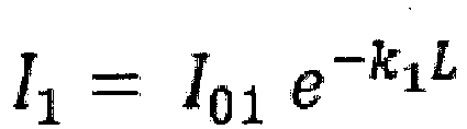
processing unit 20 is configured to calculate the ratio between the first and second signals at the inlet, which is indicative of a ratio R between the first intensity I1 detected by the first photodetector F1 and the second intensity l2 detected by the second photodetector F2. - According to the Lambert-Beer law, the first intensity I1 detected by the first photodetector F1 is equal to:
- Similarly, the second intensity I2 detected by the second photodetector is equal to:

- The ratio R between such intensities is:

- On the basis of this ratio R and by applying the Lambert-Beer law, it is therefore possible to form a physical magnitude representative of the refrigerant fluid. In particular, this physical magnitude is the molar concentration of the refrigerant fluid.
- The apparatus described and illustrated herein comprises two photodetectors. However, it could comprise further photodetectors.
- The measurements shall always be intended as ratios between a pair of intensity values measured by two photodetectors of the apparatus. The physical magnitudes characteristic of the refrigerant fluid are therefore formed by systemising the equations for the various ratios.
- The
processing unit 20 may be formed by an electronic module, suitably programmed to perform the functions described, possibly corresponding to various hardware units and/or software routines forming part of the programmed module. - Alternatively or additionally, these functions may be provided by a plurality of distributed electronic modules.
- The
processing unit 20 may also comprise one or more processors for executing the instructions contained in memory modules. - The features of the apparatus and of the method for identifying a refrigerant fluid contained in a tank or in a measuring cell of a system for recharging an air-conditioning plant according to the present invention have been clarified by the description provided, as have the advantages thereof.
- Thanks to the calculation of the ratio between intensities, the problem relating to deviations in intensity of the IR source caused by thermal fluctuations of the heating element from which it is formed has been solved. Thus, it is not necessary to perform an initial cleaning of the measuring cell or to make measurement corrections.
Claims (4)
- Apparatus (1) for identifying a refrigerant fluid contained in a tank or in measuring cell (10) of a system for recharging an air-conditioning plant, comprising:- at least one infrared source (S) configured to emit at least radiations with a first emitting intensity (I01) at a first wavelength (λ1) and with a second emitting intensity (I02) at a second wavelength (λ2), said infrared source (S) being arranged in such a way as to send infrared radiations within the refrigerant fluid contained in the tank or measuring cell (10);- a first photodetector (F1) configured to detect a first intensity (I1) of infrared radiations at the first wavelength (λ1);- a second photodetector (F2) configured to detect a second intensity (l2) of infrared radiations at the second wavelength (λ2), said first photodetector (F1) and said second photodetector (F2) being arranged in such a way as to receive the infrared radiations coming from said refrigerant fluid;characterised in that it comprises a processing unit (20) configured to:- calculate a ratio (R) between the first intensity (I1) detected by the first photodetector (F1) and the second intensity (l2) detected by the second photodetector (F2);- according to the Lambert-Beer law, obtaining from said ratio (R) a physical magnitude representative of the refrigerant fluid.
- Apparatus (1) according to claim 1, wherein said first photodetector (F1) and said second photodetector (F2) comprises each a corresponding optical filter configured to allow the passage of the infrared radiation having respectively the first wavelength (λ1) or the second wavelength (λ2).
- Method for identifying a refrigerant fluid contained in a tank or in a measuring cell (10) of a system for recharging an air-conditioning plant, comprising the steps of:- emitting in the direction of the refrigerant fluid infrared radiations with a first emitting intensity (I01) at a first wavelength (λ1) and with a second emitting intensity (I02) at a second wavelength (λ2);- detecting a first intensity (I1) of infrared radiations at the first wavelength (λ1) after the infrared radiations have passed through the refrigerant fluid;- detecting a second intensity (I2) of infrared radiations at the second wavelength (λ2) after the infrared radiations have passed through the refrigerant fluid;characterised in that it comprises the steps of:- calculating a ratio (R) between the first intensity (I1) detected upon the exit of the refrigerant fluid and the second intensity (I2) detected upon the exit of the refrigerant fluid;- according to the Lambert-Beer law, obtaining from said ratio (R) a physical magnitude representative of the refrigerant fluid.
- Computer product directly loadable in the memory of a processing unit (20), said computer product comprising portions of software code for executing the method according to claim 3.
Applications Claiming Priority (1)
| Application Number | Priority Date | Filing Date | Title |
|---|---|---|---|
| IT102019000011511A IT201900011511A1 (en) | 2019-07-11 | 2019-07-11 | APPARATUS AND METHOD FOR IDENTIFYING A REFRIGERANT FLUID PRESENT IN A TANK OR MEASURING CELL OF A REFILLING SYSTEM OF AN AIR CONDITIONING SYSTEM |
Publications (1)
| Publication Number | Publication Date |
|---|---|
| EP3764082A1 true EP3764082A1 (en) | 2021-01-13 |
Family
ID=68501938
Family Applications (1)
| Application Number | Title | Priority Date | Filing Date |
|---|---|---|---|
| EP20183634.3A Withdrawn EP3764082A1 (en) | 2019-07-11 | 2020-07-02 | Apparatus and method for identifying a refrigerant fluid contained in a tank or in a measuring cell of a system for recharging an air-conditioning plant |
Country Status (5)
| Country | Link |
|---|---|
| US (1) | US11567001B2 (en) |
| EP (1) | EP3764082A1 (en) |
| JP (1) | JP2021015121A (en) |
| CN (1) | CN112213263A (en) |
| IT (1) | IT201900011511A1 (en) |
Citations (4)
| Publication number | Priority date | Publication date | Assignee | Title |
|---|---|---|---|---|
| GB2324868A (en) * | 1997-05-01 | 1998-11-04 | Sun Electric Uk Ltd | Identification of refrigerant fluids |
| WO2017132404A1 (en) * | 2016-01-26 | 2017-08-03 | Kirby Brett S | Near-infrared spectroscopy for sensing glycogen in muscle tissue |
| US20170261427A1 (en) * | 2016-03-14 | 2017-09-14 | Analog Devices, Inc. | Optical measurements of chemical content |
| WO2019099267A1 (en) * | 2017-11-17 | 2019-05-23 | Analog Devices, Inc. | Material characteristic signal detection method and apparatus |
Family Cites Families (17)
| Publication number | Priority date | Publication date | Assignee | Title |
|---|---|---|---|---|
| JPH0560435A (en) * | 1991-09-03 | 1993-03-09 | Toshiba Corp | Sensor for refrigerant dilution degree |
| JPH08145517A (en) * | 1994-11-16 | 1996-06-07 | Sanyo Electric Co Ltd | Refrigerating equipment and measuring method of refrigerant |
| JPH09318526A (en) * | 1996-03-29 | 1997-12-12 | Japan Energy Corp | Moisture in oil detector and method for measuring water in oil |
| JP2003057178A (en) * | 2001-08-17 | 2003-02-26 | Horiba Ltd | Multicomponent analyzer |
| JP2004138453A (en) * | 2002-10-16 | 2004-05-13 | Horiba Ltd | Apparatus for analyzing mixed refrigerant |
| US20090306527A1 (en) * | 2006-02-03 | 2009-12-10 | Yasuhiro Kubo | Method of Exhaled Gas Measurement and Analysis and Apparatus Therefor |
| RU2454921C2 (en) * | 2006-07-07 | 2012-07-10 | Конинклейке Филипс Электроникс Н.В. | Optic reflecting system and method |
| US7728978B2 (en) * | 2006-10-18 | 2010-06-01 | Spectrasensors, Inc. | Detection of moisture in refrigerants |
| US8572992B2 (en) * | 2008-03-31 | 2013-11-05 | Service Solutions U.S. Llc | Method for recovery and recharge of blend refrigerants with blend sent for reclamation |
| EP2194368B1 (en) * | 2008-12-03 | 2019-07-17 | Grundfos Management A/S | Sensor system for detecting and specifying individual particles in a fluid |
| JP5531609B2 (en) * | 2009-06-23 | 2014-06-25 | ダイキン工業株式会社 | Refrigerant concentration detector |
| DE102010045643B4 (en) * | 2010-09-17 | 2013-04-11 | Continental Automotive Gmbh | sensor |
| DE102011111836A1 (en) * | 2011-08-27 | 2013-02-28 | Inficon Gmbh | Apparatus and method for refrigerant identification |
| DE102014010713A1 (en) * | 2014-07-19 | 2016-01-21 | Paragon Ag | "Gas sensor arrangement for measuring a target gas concentration" |
| DE102016223424A1 (en) * | 2016-11-25 | 2018-05-30 | Robert Bosch Gmbh | Particle measuring apparatus and method for determining a particle size |
| US10067050B2 (en) * | 2016-12-05 | 2018-09-04 | The United States Of America, As Represented By The Secretary Of Commerce | Linear absorption spectrometer to optically determine an absolute mole fraction of radiocarbon in a sample |
| CN208420693U (en) * | 2018-07-13 | 2019-01-22 | 深圳市泰路科技有限公司 | A kind of car air conditioner refrigerant concentration identification device and system |
-
2019
- 2019-07-11 IT IT102019000011511A patent/IT201900011511A1/en unknown
-
2020
- 2020-07-02 EP EP20183634.3A patent/EP3764082A1/en not_active Withdrawn
- 2020-07-03 JP JP2020115434A patent/JP2021015121A/en active Pending
- 2020-07-09 CN CN202010656259.7A patent/CN112213263A/en active Pending
- 2020-07-12 US US16/926,770 patent/US11567001B2/en active Active
Patent Citations (4)
| Publication number | Priority date | Publication date | Assignee | Title |
|---|---|---|---|---|
| GB2324868A (en) * | 1997-05-01 | 1998-11-04 | Sun Electric Uk Ltd | Identification of refrigerant fluids |
| WO2017132404A1 (en) * | 2016-01-26 | 2017-08-03 | Kirby Brett S | Near-infrared spectroscopy for sensing glycogen in muscle tissue |
| US20170261427A1 (en) * | 2016-03-14 | 2017-09-14 | Analog Devices, Inc. | Optical measurements of chemical content |
| WO2019099267A1 (en) * | 2017-11-17 | 2019-05-23 | Analog Devices, Inc. | Material characteristic signal detection method and apparatus |
Also Published As
| Publication number | Publication date |
|---|---|
| JP2021015121A (en) | 2021-02-12 |
| US20210010931A1 (en) | 2021-01-14 |
| CN112213263A (en) | 2021-01-12 |
| IT201900011511A1 (en) | 2021-01-11 |
| US11567001B2 (en) | 2023-01-31 |
Similar Documents
| Publication | Publication Date | Title |
|---|---|---|
| CN101617212B (en) | In-Line Sensors for Monitoring Chemical Contamination in Hydraulic Fluids | |
| KR20190040278A (en) | Water quality detection | |
| US10031075B2 (en) | Device and method for identifying refrigerants | |
| WO2015015750A1 (en) | Inline concentration meter and concentration detection method | |
| US10788416B2 (en) | Multiple wavelength light source for colorimetric measurement | |
| KR101793376B1 (en) | FTIR measurement system incorporating moisture removal system of sample gas | |
| US9816846B2 (en) | Apparatus and method for determining a non-condensable gas parameter | |
| US20130050680A1 (en) | System and methods for making temperature and pressure measurements utilizing a tunable laser diode | |
| US11567001B2 (en) | Apparatus and method for identifying a refrigerant fluid contained in a tank or in measuring cell of a system for recharging an air-conditioning plant | |
| US20050062972A1 (en) | System and method for cavity ring-down spectroscopy using continuously varying continuous wave excitation | |
| US20160153897A1 (en) | Chlorine dioxide gas concentration measuring apparatus | |
| CN107703096B (en) | A kind of method for detecting moisture and/or urea content in isocyanate and application of online monitoring | |
| CN105784618B (en) | Solution liquid film parameter measuring apparatus and method on a kind of non-transmissive surface of solids | |
| US10024751B2 (en) | Fluid system evaluation with multiple chemical tracers | |
| JP2011053047A (en) | Surface temperature measuring method, surface temperature measuring apparatus, and steel manufacturing method | |
| KR20180048644A (en) | Method and apparatus for measuring substance concentration or substance in a liquid medium | |
| JP2008164487A (en) | Analysis equipment for semiconductor manufacturing systems | |
| US20230011975A1 (en) | Method of determining an optical pathlength through a cuvette | |
| CN106596433A (en) | Water quality detection system provided with heating system | |
| KR20100074600A (en) | Method for measuring concentration of a component of mixed solution | |
| EP3189314B1 (en) | Furnace atmosphere measurement | |
| US20110222055A1 (en) | Determination of the salt concentration of an aqueous solution | |
| JP2003014632A (en) | Gas pressure correction method and correction system for gas concentration monitor by ultraviolet absorption etc. | |
| KR20010102600A (en) | Development og UV-Absosrption Type In-Line Ozone Concentration Measuring Eguiment | |
| JP2003014633A (en) | SO3 concentration meter |
Legal Events
| Date | Code | Title | Description |
|---|---|---|---|
| PUAI | Public reference made under article 153(3) epc to a published international application that has entered the european phase |
Free format text: ORIGINAL CODE: 0009012 |
|
| STAA | Information on the status of an ep patent application or granted ep patent |
Free format text: STATUS: THE APPLICATION HAS BEEN PUBLISHED |
|
| AK | Designated contracting states |
Kind code of ref document: A1 Designated state(s): AL AT BE BG CH CY CZ DE DK EE ES FI FR GB GR HR HU IE IS IT LI LT LU LV MC MK MT NL NO PL PT RO RS SE SI SK SM TR |
|
| AX | Request for extension of the european patent |
Extension state: BA ME |
|
| STAA | Information on the status of an ep patent application or granted ep patent |
Free format text: STATUS: THE APPLICATION IS DEEMED TO BE WITHDRAWN |
|
| 18D | Application deemed to be withdrawn |
Effective date: 20210714 |