EP3763897B1 - Hubanker für eine mauer mit integrierter schalung, und mauer mit integrierter schalung, die einen solchen hubanker umfasst - Google Patents
Hubanker für eine mauer mit integrierter schalung, und mauer mit integrierter schalung, die einen solchen hubanker umfasst Download PDFInfo
- Publication number
- EP3763897B1 EP3763897B1 EP20185299.3A EP20185299A EP3763897B1 EP 3763897 B1 EP3763897 B1 EP 3763897B1 EP 20185299 A EP20185299 A EP 20185299A EP 3763897 B1 EP3763897 B1 EP 3763897B1
- Authority
- EP
- European Patent Office
- Prior art keywords
- wall
- integrated
- lifting anchor
- end portion
- branches
- Prior art date
- Legal status (The legal status is an assumption and is not a legal conclusion. Google has not performed a legal analysis and makes no representation as to the accuracy of the status listed.)
- Active
Links
Images

Classifications
-
- E—FIXED CONSTRUCTIONS
- E04—BUILDING
- E04G—SCAFFOLDING; FORMS; SHUTTERING; BUILDING IMPLEMENTS OR AIDS, OR THEIR USE; HANDLING BUILDING MATERIALS ON THE SITE; REPAIRING, BREAKING-UP OR OTHER WORK ON EXISTING BUILDINGS
- E04G21/00—Preparing, conveying, or working-up building materials or building elements in situ; Other devices or measures for constructional work
- E04G21/14—Conveying or assembling building elements
- E04G21/142—Means in or on the elements for connecting same to handling apparatus
- E04G21/145—Means in or on the elements for connecting same to handling apparatus specific for hollow plates
Definitions
- the present invention relates to a lifting anchor for an integrated formwork wall and to an integrated formwork wall comprising such a lifting anchor.
- an integrated formwork wall comprises a first wall and a second wall substantially parallel to each other.
- a plurality of connection elements is further provided for connecting and maintaining the first wall and the second wall at a distance from each other, so as to form a filling space between them.
- These connection elements are at least partly embedded in the first wall and the second wall and extend through the filling space.
- structural reinforcements, embedded inside the first wall and/or the second wall are also provided for reinforcing the structure of the first wall and/or the second wall.
- Lifting anchors such as lifting loops or hooks
- Lifting anchors are usually integrated into an integrated formwork wall to allow it to be handled with handling equipment, such as a crane.
- Built-in formwork walls are usually manufactured in a factory and then transported to a construction site for the construction of interior walls and/or exterior walls. After the built-in formwork wall is installed on the construction site, its filling space forms a formwork which is filled with at least one hydraulic material, for example concrete.
- the structural reinforcements and the lifting anchors are at least partially embedded in a hydraulic material of the first and second walls of the integrated formwork wall, for example concrete. After assembling the first and second walls of the integrated formwork wall, the latter can be handled using the lifting anchors. In fact, certain metal portions of the lifting anchors are not embedded in the hydraulic material and are visible and accessible from space existing filling between the first and second walls. Thanks to this arrangement, the lifting anchors can be connected to the handling equipment.
- Lifting hooks are known in particular from the publication FROM 299 14 138 U1 and are composed of a long U-shaped curved rod having two branches substantially parallel to each other and which are anchored respectively in the first and second walls of the integrated formwork wall over a significant length to ensure the sealing of the lifting hook.
- a stop which is arranged transversely to the first and second branches and welded to them, is also provided to absorb the pinching forces, in order to prevent the lifting hook from coming loose.
- This stop has a diameter which can be between 25 millimeters and 28 millimeters. This stop protrudes on either side of the first and second branches by a distance of between 8 millimeters and 12 millimeters.
- the first and second branches protrude from the stop over a length of between 300 millimeters and 400 millimeters. Due to the length of the first and second branches, these lifting hooks have the disadvantage of being very bulky and requiring minimum embedding in the walls of the integrated formwork wall, which imposes constraints during manufacture on the positioning of the lifting hooks relative to the structural reinforcements of the first and second walls. Finally, this type of lifting hook generally has a maximum useful load CMU of approximately 2.4 tonnes.
- a lifting hook proposed to prevent loosening and which has the particularity of comprising a glued laminated timber stop forming a compression member which comprises notches in which a portion of the section of the metal branches of the lifting hook fits.
- This stop only prevents the metal part from deforming during lifting. More particularly, under the effect of the lifting force, the two metal branches tend to move closer together. The stop prevents the metal branches from moving closer together.
- an internal anchoring of the metal branches in the concrete of at least 1 cm is necessary.
- the present invention aims to overcome at least one of the aforementioned drawbacks by providing a space-saving solution, easy to integrate into an integrated formwork wall, which guarantees a maximum useful load CMU complying with the standards in force and which avoids degradation of the properties of the integrated formwork wall.
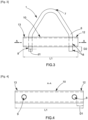
- the invention relates to a lifting anchor 1 for an integrated formwork wall 2.
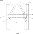
- Said integrated formwork wall 2 which is shown in the figure 5 comprises a first wall 3 made of hydraulic material, preferably concrete, arranged in a first plane P1, a second wall 4 made of hydraulic material, preferably concrete, arranged in a second plane P2, the first plane P1 and the second plane P2 being substantially parallel to each other, and at least one connection element (not shown) for connecting and maintaining the first wall 3 and the second wall 4 at a distance from each other, so as to form between them a filling space 5 of thickness E capable and intended to be filled with at least one hydraulic material, preferably concrete.
- the compression element 10 can be anchored at the level of the first end portion 12 and the second end portion 13 respectively in the first wall 3 and in the second wall 4 by undergoing essentially shear forces during the lifting operation with a handling machine which would exert a lifting force on the folded base 7.
- the buckling stresses known from the prior art with the lifting axes have completely disappeared. Indeed, during the lifting operation, the shear forces are transmitted to the first end portion 12 and the second end portion 13, flush with the first and second walls 3, 4. It is for these reasons that the dimensions of the section of the compression element 10 can be considerably reduced, compared to those of the lifting axes of the prior art.
- an integrated formwork wall having a thickness of 40 centimeters will only need a compression element 10 having a section of 45 millimeters in diameter while a lifting axis known from the prior art will require a section of 100 millimeters in diameter to be able to guarantee a maximum useful load CMU of 4 tons.
- This reduction in the dimension of the section of the compression element 10 makes it possible to overcome the problem of watertightness known from the prior art. It also results from this advantageous configuration and this particular selection, that the first and second branches 8, 9 of the lifting anchor 1 no longer have to be coated respectively in the first and second walls 3, 4, but they can simply protrude into the filling space 5 as illustrated in figure 5 .
- the lifting anchor 1 is particularly easy to integrate into the integrated formwork wall 2, since it is no longer necessary to take into account the positioning of the structural reinforcements of the first and second walls 3, 4 to position the lifting anchor 1.
- the tests carried out have given maximum useful loads CMU of around 3.8 tonnes, which considerably reduces the number of lifting anchors 1 to be used to lift large loads and which also limits the use of load balancing systems which are essential beyond two lifting anchors 1 per integrated formwork wall 2.
- the first and second branches 8, 9 project relative to the compression element 10 by a distance D2 of between 15 millimeters and 25 millimeters ( figure 3 ).
- the lifting anchor 1 since the sealing of the first and second branches 8, 9 respectively in the first and second walls 3, 4 is no longer required, their size can be drastically reduced. Consequently, the lifting anchor 1 has the advantage of being very compact since the first and second branches 8, 9 have very small dimensions. The lifting anchor 1 is thus easy to handle and store.
- connection means 11 consist of a weld ( figure 1 ).
- connection means 11 consist of a nut and threaded rod assembly ( figure 2 ).
- the length L1 of the compression element 10 is between 120 millimeters and 560 millimeters ( figures 2 And 3 ).
- the lifting anchor 1 is suitable for being integrated into walls with integrated formwork 2 whose thickness E1 is between 160 millimeters and 600 millimeters ( figure 5 ).
- the section of said compression element 10 has a substantially circular or rectangular or square shape.
- the compression element 10 may be solid or hollow ( Figures 1 and 2 ).
- the compression element 10 is preferably made of a profile made of metallic or similar material.
- the elongated metal element 6 may be chosen from a rod or a cable, preferably made of metal or carbon fiber, the rigidity and strength of which allow it to be bent, preferably in the shape of a U or V.
- the section of the metal element 6 preferably has a diameter d1 of between 8 and 20 millimeters ( figure 3 ).
- the invention also relates to an integrated formwork wall 2 as shown in figure 5 , which is characterized in that it comprises at least one lifting anchor 1 as described according to the invention.
- the first and second branches 8, 9 are arranged in the filling space 5.
- the lifting anchor 1 is particularly easy to integrate into the integrated formwork wall 2 during the manufacture of the latter, since it is no longer necessary to take into account the positioning of the structural reinforcements of the first and second walls 3, 4 to position the lifting anchor 1.
- first and second branches 8, 9 are integrated into the hydraulic material respectively of the first wall 3 and the second wall 4.
- said first end portion 12 and said second end portion 13 of the compression element 10 of the lifting anchor 1 are integrated into the hydraulic material respectively of the first wall 3 and the second wall 4 over an internal anchoring distance D3 of between 15 millimeters and 25 millimeters.
- the internal anchoring distance D3 is measured between the internal face of the first wall 3 or the second wall 4 and the edge of said first end portion 12 or said second end portion 13.
- This advantageous arrangement allows the compression element 10 to take up the shear forces which are transmitted at the level of said first end portion 12 and said second end portion 13 during the handling operation by a handling machine which would exert a lifting force on the folded base 7. This avoids the buckling of the compression element 10 which occurs in particular for the large diameters known from the prior art and when the lifting force is exerted directly on the compression element 10.
- said first end portion 12 and said second end portion 13 of the compression element 10 of the lifting anchor 1 are integrated and anchored in the hydraulic material respectively of the first wall 3 and of the second wall 4, leaving an external coating distance D4 preferably greater than or equal to 15 millimeters.
- the external coating distance D4 is measured between the external face of the first wall 3 or the second wall 4 and the edge of said first end portion 12 or said second end portion 13.
Landscapes
- Engineering & Computer Science (AREA)
- Architecture (AREA)
- Mechanical Engineering (AREA)
- Civil Engineering (AREA)
- Structural Engineering (AREA)
- Conveying And Assembling Of Building Elements In Situ (AREA)
- Forms Removed On Construction Sites Or Auxiliary Members Thereof (AREA)
Claims (9)
- Hubanker (1) für eine Mauer mit integrierter Schalung (2), wobei die Mauer mit integrierter Schalung (2) eine erste Wand (3) aus hydraulischem Material aufweist, die in einer ersten Ebene (P1) angeordnet ist, eine zweite Wand (4) aus hydraulischem Material, die in einer zweiten Ebene (P2) angeordnet ist, wobei die erste Ebene (P1) und die zweite Ebene (P2) im Wesentlichen parallel zueinander sind, und mindestens ein Verbindungselement, um die erste Wand (3) und die zweite Wand (4) miteinander zu verbinden und voneinander fernzuhalten, so dass zwischen ihnen ein Füllraum (5) mit einer Dicke (E) gebildet wird, der geeignet und dazu bestimmt ist, mit mindestens einem hydraulischen Material gefüllt zu werden, wobei der Hubanker (1) Folgendes aufweist:- ein längliches, gebogenes, vorzugsweise im Wesentlichen U-förmiges Metallelement (6), das eine gebogene Basis (7), einen ersten Schenkel (8) und einen zweiten Schenkel (9) aufweist, die vorzugsweise im Wesentlichen parallel zueinander verlaufen und in einer Ebene angeordnet sind, wobei die gebogene Basis (7) den ersten und den zweiten Schenkel (8, 9) miteinander verbindet und so konfiguriert ist, dass sie in den Füllraum (5) hineinragt, und so konfiguriert ist, dass sie mit einem Handhabungsgerät verbunden werden kann,- ein quer verlaufendes Kompressionselement (10), das senkrecht zu dem ersten und dem zweiten Schenkel (8, 9) angeordnet ist und mit dem ersten und dem zweiten Schenkel (8, 9) durch Verbindungsmittel (11) verbunden ist, wobei das Kompressionselement (10) einen ersten Endabschnitt (12) und einen zweiten Endabschnitt (13) aufweist, die jeweils von dem ersten Schenkel (8) und dem zweiten Schenkel (9) vorstehen, wobei der Hubanker (1) dadurch gekennzeichnet ist, dass:- das Kompressionselement (10) einen Querschnitt mit einer Größe zwischen 1600 Quadratmillimetern und 23000 Quadratmillimetern aufweist,- der erste Endabschnitt (12) und der zweite Endabschnitt (13) jeweils von dem ersten Schenkel (8) und dem zweiten Schenkel (9) um einen Abstand (D1) zwischen 15 Millimetern und 25 Millimetern vorstehen.
- Hubanker nach Anspruch 1, dadurch gekennzeichnet, dass der erste und der zweite Schenkel (8, 9) relativ zum Kompressionselement (10) um einen Abstand (D2) zwischen 15 Millimetern und 25 Millimetern vorstehen.
- Hubanker nach einem der Ansprüche 1 bis 2, dadurch gekennzeichnet, dass die Verbindungsmittel (11) aus einer Schweißung oder einer Anordnung aus Mutter und Gewindestange ausgewählt sind.
- Hubanker nach einem der Ansprüche 1 bis 3, dadurch gekennzeichnet, dass die Länge (L1) des Kompressionselements (10) zwischen 120 Millimetern und 560 Millimetern liegt.
- Hubanker nach einem der Ansprüche 1 bis 4, dadurch gekennzeichnet, dass der Querschnitt des Kompressionselements (10) eine kreisförmige oder rechteckige oder quadratische Form aufweist.
- Mauer mit integrierter Schalung (2), dadurch gekennzeichnet, dass die integrierte Schalung (2) mindestens einen Hubanker (1) nach einem der Ansprüche 1 bis 5 aufweist, wobei die integrierte Schalung (2) Folgendes aufweist:- eine erste Wand (3) aus hydraulischem Material, die in einer ersten Ebene (P1) angeordnet ist,- eine zweite Wand (4) aus hydraulischem Material, die in einer zweiten Ebene (P2) angeordnet ist, wobei die erste Ebene (P1) und die zweite Ebene (P2) im Wesentlichen parallel zueinander sind, und- mindestens ein Verbindungselement, um die erste Wand (3) und die zweite Wand (4) miteinander zu verbinden und voneinander fernzuhalten, so dass zwischen ihnen ein Füllraum (5) mit einer Dicke (E) gebildet wird, der geeignet und dazu bestimmt ist, mit mindestens einem hydraulischen Material gefüllt zu werden,wobei der erste Endabschnitt (12) und der zweite Endabschnitt (13) des Kompressionselements (10) des Hubankers (1) in das hydraulische Material der ersten Wand (3) bzw. der zweiten Wand (4) eingebettet sind, wobei die gebogene Basis (7) zumindest teilweise in den Füllraum (5) hineinragt und so konfiguriert ist, dass sie mit einem Handhabungsgerät verbunden werden kann.
- Mauer mit integrierter Schalung nach Anspruch 6, dadurch gekennzeichnet, dass der erste und der zweite Schenkel (8, 9) im Füllraum (5) angeordnet sind.
- Mauer mit integrierter Schalung nach Anspruch 6, dadurch gekennzeichnet, dass der erste und der zweite Schenkel (8, 9) in das hydraulische Material der ersten Wand (3) bzw. der zweiten Wand (4) eingebettet sind.
- Mauer mit integrierter Schalung nach einem der Ansprüche 6 bis 8, dadurch gekennzeichnet, dass der erste Endabschnitt (12) und der zweite Endabschnitt (13) des Kompressionselements (10) des Hubankers (1) in das hydraulische Material der ersten Wand (3) bzw. der zweiten Wand (4) über einen inneren Verankerungsabstand (D3) zwischen 15 Millimetern und 25 Millimetern eingebettet sind.
Applications Claiming Priority (1)
| Application Number | Priority Date | Filing Date | Title |
|---|---|---|---|
| FR1907748A FR3098534B1 (fr) | 2019-07-10 | 2019-07-10 | Ancre de levage pour mur à coffrage intégré et mur à coffrage intégré comportant ladite ancre de levage |
Publications (2)
| Publication Number | Publication Date |
|---|---|
| EP3763897A1 EP3763897A1 (de) | 2021-01-13 |
| EP3763897B1 true EP3763897B1 (de) | 2024-09-18 |
Family
ID=68501745
Family Applications (1)
| Application Number | Title | Priority Date | Filing Date |
|---|---|---|---|
| EP20185299.3A Active EP3763897B1 (de) | 2019-07-10 | 2020-07-10 | Hubanker für eine mauer mit integrierter schalung, und mauer mit integrierter schalung, die einen solchen hubanker umfasst |
Country Status (2)
| Country | Link |
|---|---|
| EP (1) | EP3763897B1 (de) |
| FR (1) | FR3098534B1 (de) |
Families Citing this family (1)
| Publication number | Priority date | Publication date | Assignee | Title |
|---|---|---|---|---|
| CN113353781B (zh) * | 2021-05-17 | 2023-08-15 | 台州优匠建筑科技有限公司 | 一种吊点侧置的预制墙板构件吊运装置 |
Family Cites Families (6)
| Publication number | Priority date | Publication date | Assignee | Title |
|---|---|---|---|---|
| DE29914138U1 (de) | 1999-08-12 | 1999-12-16 | Syspro-Gruppe Betonbauteile e.V., 68766 Hockenheim | Transportanker für sogenannte Doppelwände |
| DE10116673A1 (de) * | 2001-04-04 | 2002-10-10 | Hans-Werner Dausend | Transportanker |
| DE10127870A1 (de) * | 2001-06-08 | 2002-12-12 | Georg Weidner | Transport- oder Verlegeanker für Hohl- und Filigranwände mit Arretier- oder Sicherungsabschnitt |
| DE102005009708B4 (de) | 2005-03-03 | 2009-08-13 | Pape, Heinz, Dr.-Ing | Transportanker für vorgefertigte Stahlbetonelemente |
| DE202014103774U1 (de) * | 2014-08-14 | 2015-11-17 | Philipp Gmbh | Hohlwandanker |
| FR3034791B1 (fr) | 2015-04-09 | 2018-05-25 | Spurgin Leonhart | Mur a coffrage integre avec un moyen amovible de reception d'un moyen de raccordement a un engin de manutention |
-
2019
- 2019-07-10 FR FR1907748A patent/FR3098534B1/fr active Active
-
2020
- 2020-07-10 EP EP20185299.3A patent/EP3763897B1/de active Active
Also Published As
| Publication number | Publication date |
|---|---|
| EP3763897A1 (de) | 2021-01-13 |
| FR3098534A1 (fr) | 2021-01-15 |
| FR3098534B1 (fr) | 2021-07-30 |
Similar Documents
| Publication | Publication Date | Title |
|---|---|---|
| EP0434819B1 (de) | Hebe- und aufrichtanker, insbesondere für betonplatten | |
| FR2746867A1 (fr) | Assemblage entre des barres ou des tubes en materiaux composites renforces par des fibres | |
| FR2822177A1 (fr) | Dispositif d'ancrage pour armatures de precontrainte, systeme de precontrainte incluant le dispositif, et armature appropriee | |
| EP3763897B1 (de) | Hubanker für eine mauer mit integrierter schalung, und mauer mit integrierter schalung, die einen solchen hubanker umfasst | |
| EP2889439B1 (de) | Verankerungsvorrichtung mit Verstrebungen für kreisförmige Bewehrungen | |
| FR3112566A1 (fr) | Organe de levage pour le levage d’un prémur. | |
| EP2000605A2 (de) | Vorrichtung und Zubehörteile zur Sicherstellung der Isolierung an thermischen Trennungen in Gebäudeisolierung | |
| FR3021625A1 (fr) | Liaison flexible entre la structure plancher et la structure de coque d'un aeronef. | |
| CA2200677C (fr) | Systeme d'assemblage de panneaux prefabriques pour la realisation d'une cloison de piscine et cloison de piscine ainsi obtenue | |
| BE1008652A6 (fr) | Pylone pourvu d'un manchon conique interieur. | |
| FR2866908A1 (fr) | Revetement de surface provisoire a lames articulees | |
| EP1956156B1 (de) | Anschluss zur Verbindung von zwei Platten einer Mauer mit verlorener Verschalung | |
| FR2529601A1 (fr) | Ancrage de fixation de pieces de montage, destine a une armature pour element en beton arme | |
| EP2060687A1 (de) | Vorrichtung zur Sicherstellung der Isolierung bei thermischer Trennung | |
| EP2186722A1 (de) | Verankerungsvorrichtung eines Elements an einer Wand und Struktur ausgestattet mit einer solchen Vorrichtung | |
| FR2756302A1 (fr) | Amelioration aux barrieres de securite | |
| FR3098533A1 (fr) | Ancre de levage, mur à coffrage intégré intégrant ladite ancre de levage, et procédé de fabrication de ladite ancre de levage | |
| FR2944542A1 (fr) | Etai de soutien. | |
| FR2940337A1 (fr) | Poutrelle metallique pour la fabrication de planchers | |
| WO2018229426A1 (fr) | Élément de structure a précontrainte provisoire | |
| EP3073018A1 (de) | Erdbebensicheres zugankersystem für die feste verbindung von betonfundamenten eines bauwerks | |
| FR2931857A1 (fr) | Douille de levage | |
| FR2688102A1 (fr) | Dispositif elastique de maintien de boitiers d'appareillage electrique entre des banches. | |
| FR3021258A3 (fr) | Plot de suspension pour element de suspension d'une ligne d'echappement de vehicule automobile | |
| FR3026065A1 (fr) | Pendule de connexion et son dispositif de suspension |
Legal Events
| Date | Code | Title | Description |
|---|---|---|---|
| PUAI | Public reference made under article 153(3) epc to a published international application that has entered the european phase |
Free format text: ORIGINAL CODE: 0009012 |
|
| STAA | Information on the status of an ep patent application or granted ep patent |
Free format text: STATUS: THE APPLICATION HAS BEEN PUBLISHED |
|
| AK | Designated contracting states |
Kind code of ref document: A1 Designated state(s): AL AT BE BG CH CY CZ DE DK EE ES FI FR GB GR HR HU IE IS IT LI LT LU LV MC MK MT NL NO PL PT RO RS SE SI SK SM TR |
|
| AX | Request for extension of the european patent |
Extension state: BA ME |
|
| STAA | Information on the status of an ep patent application or granted ep patent |
Free format text: STATUS: REQUEST FOR EXAMINATION WAS MADE |
|
| 17P | Request for examination filed |
Effective date: 20210707 |
|
| RBV | Designated contracting states (corrected) |
Designated state(s): AL AT BE BG CH CY CZ DE DK EE ES FI FR GB GR HR HU IE IS IT LI LT LU LV MC MK MT NL NO PL PT RO RS SE SI SK SM TR |
|
| P01 | Opt-out of the competence of the unified patent court (upc) registered |
Effective date: 20230622 |
|
| GRAP | Despatch of communication of intention to grant a patent |
Free format text: ORIGINAL CODE: EPIDOSNIGR1 |
|
| STAA | Information on the status of an ep patent application or granted ep patent |
Free format text: STATUS: GRANT OF PATENT IS INTENDED |
|
| INTG | Intention to grant announced |
Effective date: 20240426 |
|
| GRAS | Grant fee paid |
Free format text: ORIGINAL CODE: EPIDOSNIGR3 |
|
| GRAA | (expected) grant |
Free format text: ORIGINAL CODE: 0009210 |
|
| STAA | Information on the status of an ep patent application or granted ep patent |
Free format text: STATUS: THE PATENT HAS BEEN GRANTED |
|
| AK | Designated contracting states |
Kind code of ref document: B1 Designated state(s): AL AT BE BG CH CY CZ DE DK EE ES FI FR GB GR HR HU IE IS IT LI LT LU LV MC MK MT NL NO PL PT RO RS SE SI SK SM TR |
|
| REG | Reference to a national code |
Ref country code: GB Ref legal event code: FG4D Free format text: NOT ENGLISH |
|
| RIN1 | Information on inventor provided before grant (corrected) |
Inventor name: TORNATORE, PINO Inventor name: LENGES, MARC |
|
| REG | Reference to a national code |
Ref country code: CH Ref legal event code: EP |
|
| REG | Reference to a national code |
Ref country code: IE Ref legal event code: FG4D Free format text: LANGUAGE OF EP DOCUMENT: FRENCH |
|
| REG | Reference to a national code |
Ref country code: DE Ref legal event code: R096 Ref document number: 602020037815 Country of ref document: DE |
|
| REG | Reference to a national code |
Ref country code: LT Ref legal event code: MG9D |
|
| PG25 | Lapsed in a contracting state [announced via postgrant information from national office to epo] |
Ref country code: NO Free format text: LAPSE BECAUSE OF FAILURE TO SUBMIT A TRANSLATION OF THE DESCRIPTION OR TO PAY THE FEE WITHIN THE PRESCRIBED TIME-LIMIT Effective date: 20241218 |
|
| PG25 | Lapsed in a contracting state [announced via postgrant information from national office to epo] |
Ref country code: GR Free format text: LAPSE BECAUSE OF FAILURE TO SUBMIT A TRANSLATION OF THE DESCRIPTION OR TO PAY THE FEE WITHIN THE PRESCRIBED TIME-LIMIT Effective date: 20241219 Ref country code: FI Free format text: LAPSE BECAUSE OF FAILURE TO SUBMIT A TRANSLATION OF THE DESCRIPTION OR TO PAY THE FEE WITHIN THE PRESCRIBED TIME-LIMIT Effective date: 20240918 |
|
| PG25 | Lapsed in a contracting state [announced via postgrant information from national office to epo] |
Ref country code: BG Free format text: LAPSE BECAUSE OF FAILURE TO SUBMIT A TRANSLATION OF THE DESCRIPTION OR TO PAY THE FEE WITHIN THE PRESCRIBED TIME-LIMIT Effective date: 20240918 |
|
| PG25 | Lapsed in a contracting state [announced via postgrant information from national office to epo] |
Ref country code: LV Free format text: LAPSE BECAUSE OF FAILURE TO SUBMIT A TRANSLATION OF THE DESCRIPTION OR TO PAY THE FEE WITHIN THE PRESCRIBED TIME-LIMIT Effective date: 20240918 |
|
| PG25 | Lapsed in a contracting state [announced via postgrant information from national office to epo] |
Ref country code: HR Free format text: LAPSE BECAUSE OF FAILURE TO SUBMIT A TRANSLATION OF THE DESCRIPTION OR TO PAY THE FEE WITHIN THE PRESCRIBED TIME-LIMIT Effective date: 20240918 |
|
| REG | Reference to a national code |
Ref country code: NL Ref legal event code: MP Effective date: 20240918 |
|
| PG25 | Lapsed in a contracting state [announced via postgrant information from national office to epo] |
Ref country code: RS Free format text: LAPSE BECAUSE OF FAILURE TO SUBMIT A TRANSLATION OF THE DESCRIPTION OR TO PAY THE FEE WITHIN THE PRESCRIBED TIME-LIMIT Effective date: 20241218 |
|
| PG25 | Lapsed in a contracting state [announced via postgrant information from national office to epo] |
Ref country code: RS Free format text: LAPSE BECAUSE OF FAILURE TO SUBMIT A TRANSLATION OF THE DESCRIPTION OR TO PAY THE FEE WITHIN THE PRESCRIBED TIME-LIMIT Effective date: 20241218 Ref country code: NO Free format text: LAPSE BECAUSE OF FAILURE TO SUBMIT A TRANSLATION OF THE DESCRIPTION OR TO PAY THE FEE WITHIN THE PRESCRIBED TIME-LIMIT Effective date: 20241218 Ref country code: LV Free format text: LAPSE BECAUSE OF FAILURE TO SUBMIT A TRANSLATION OF THE DESCRIPTION OR TO PAY THE FEE WITHIN THE PRESCRIBED TIME-LIMIT Effective date: 20240918 Ref country code: HR Free format text: LAPSE BECAUSE OF FAILURE TO SUBMIT A TRANSLATION OF THE DESCRIPTION OR TO PAY THE FEE WITHIN THE PRESCRIBED TIME-LIMIT Effective date: 20240918 Ref country code: GR Free format text: LAPSE BECAUSE OF FAILURE TO SUBMIT A TRANSLATION OF THE DESCRIPTION OR TO PAY THE FEE WITHIN THE PRESCRIBED TIME-LIMIT Effective date: 20241219 Ref country code: FI Free format text: LAPSE BECAUSE OF FAILURE TO SUBMIT A TRANSLATION OF THE DESCRIPTION OR TO PAY THE FEE WITHIN THE PRESCRIBED TIME-LIMIT Effective date: 20240918 Ref country code: BG Free format text: LAPSE BECAUSE OF FAILURE TO SUBMIT A TRANSLATION OF THE DESCRIPTION OR TO PAY THE FEE WITHIN THE PRESCRIBED TIME-LIMIT Effective date: 20240918 |
|
| REG | Reference to a national code |
Ref country code: AT Ref legal event code: MK05 Ref document number: 1724814 Country of ref document: AT Kind code of ref document: T Effective date: 20240918 |
|
| PG25 | Lapsed in a contracting state [announced via postgrant information from national office to epo] |
Ref country code: NL Free format text: LAPSE BECAUSE OF FAILURE TO SUBMIT A TRANSLATION OF THE DESCRIPTION OR TO PAY THE FEE WITHIN THE PRESCRIBED TIME-LIMIT Effective date: 20240918 |
|
| PG25 | Lapsed in a contracting state [announced via postgrant information from national office to epo] |
Ref country code: PT Free format text: LAPSE BECAUSE OF FAILURE TO SUBMIT A TRANSLATION OF THE DESCRIPTION OR TO PAY THE FEE WITHIN THE PRESCRIBED TIME-LIMIT Effective date: 20250120 Ref country code: IS Free format text: LAPSE BECAUSE OF FAILURE TO SUBMIT A TRANSLATION OF THE DESCRIPTION OR TO PAY THE FEE WITHIN THE PRESCRIBED TIME-LIMIT Effective date: 20250118 |
|
| PG25 | Lapsed in a contracting state [announced via postgrant information from national office to epo] |
Ref country code: RO Free format text: LAPSE BECAUSE OF FAILURE TO SUBMIT A TRANSLATION OF THE DESCRIPTION OR TO PAY THE FEE WITHIN THE PRESCRIBED TIME-LIMIT Effective date: 20240918 Ref country code: SM Free format text: LAPSE BECAUSE OF FAILURE TO SUBMIT A TRANSLATION OF THE DESCRIPTION OR TO PAY THE FEE WITHIN THE PRESCRIBED TIME-LIMIT Effective date: 20240918 |
|
| PG25 | Lapsed in a contracting state [announced via postgrant information from national office to epo] |
Ref country code: ES Free format text: LAPSE BECAUSE OF FAILURE TO SUBMIT A TRANSLATION OF THE DESCRIPTION OR TO PAY THE FEE WITHIN THE PRESCRIBED TIME-LIMIT Effective date: 20240918 |
|
| PG25 | Lapsed in a contracting state [announced via postgrant information from national office to epo] |
Ref country code: EE Free format text: LAPSE BECAUSE OF FAILURE TO SUBMIT A TRANSLATION OF THE DESCRIPTION OR TO PAY THE FEE WITHIN THE PRESCRIBED TIME-LIMIT Effective date: 20240918 Ref country code: AT Free format text: LAPSE BECAUSE OF FAILURE TO SUBMIT A TRANSLATION OF THE DESCRIPTION OR TO PAY THE FEE WITHIN THE PRESCRIBED TIME-LIMIT Effective date: 20240918 |
|
| PG25 | Lapsed in a contracting state [announced via postgrant information from national office to epo] |
Ref country code: CZ Free format text: LAPSE BECAUSE OF FAILURE TO SUBMIT A TRANSLATION OF THE DESCRIPTION OR TO PAY THE FEE WITHIN THE PRESCRIBED TIME-LIMIT Effective date: 20240918 Ref country code: PL Free format text: LAPSE BECAUSE OF FAILURE TO SUBMIT A TRANSLATION OF THE DESCRIPTION OR TO PAY THE FEE WITHIN THE PRESCRIBED TIME-LIMIT Effective date: 20240918 |
|
| PG25 | Lapsed in a contracting state [announced via postgrant information from national office to epo] |
Ref country code: IT Free format text: LAPSE BECAUSE OF FAILURE TO SUBMIT A TRANSLATION OF THE DESCRIPTION OR TO PAY THE FEE WITHIN THE PRESCRIBED TIME-LIMIT Effective date: 20240918 Ref country code: SK Free format text: LAPSE BECAUSE OF FAILURE TO SUBMIT A TRANSLATION OF THE DESCRIPTION OR TO PAY THE FEE WITHIN THE PRESCRIBED TIME-LIMIT Effective date: 20240918 |
|
| REG | Reference to a national code |
Ref country code: DE Ref legal event code: R097 Ref document number: 602020037815 Country of ref document: DE |
|
| PG25 | Lapsed in a contracting state [announced via postgrant information from national office to epo] |
Ref country code: DK Free format text: LAPSE BECAUSE OF FAILURE TO SUBMIT A TRANSLATION OF THE DESCRIPTION OR TO PAY THE FEE WITHIN THE PRESCRIBED TIME-LIMIT Effective date: 20240918 |
|
| PLBE | No opposition filed within time limit |
Free format text: ORIGINAL CODE: 0009261 |
|
| STAA | Information on the status of an ep patent application or granted ep patent |
Free format text: STATUS: NO OPPOSITION FILED WITHIN TIME LIMIT |
|
| 26N | No opposition filed |
Effective date: 20250619 |
|
| PG25 | Lapsed in a contracting state [announced via postgrant information from national office to epo] |
Ref country code: SE Free format text: LAPSE BECAUSE OF FAILURE TO SUBMIT A TRANSLATION OF THE DESCRIPTION OR TO PAY THE FEE WITHIN THE PRESCRIBED TIME-LIMIT Effective date: 20240918 |
|
| PGFP | Annual fee paid to national office [announced via postgrant information from national office to epo] |
Ref country code: DE Payment date: 20250722 Year of fee payment: 6 |
|
| PGFP | Annual fee paid to national office [announced via postgrant information from national office to epo] |
Ref country code: FR Payment date: 20250725 Year of fee payment: 6 |
|
| REG | Reference to a national code |
Ref country code: CH Ref legal event code: U11 Free format text: ST27 STATUS EVENT CODE: U-0-0-U10-U11 (AS PROVIDED BY THE NATIONAL OFFICE) Effective date: 20260115 |
|
| PG25 | Lapsed in a contracting state [announced via postgrant information from national office to epo] |
Ref country code: LU Free format text: LAPSE BECAUSE OF NON-PAYMENT OF DUE FEES Effective date: 20250710 |
|
| GBPC | Gb: european patent ceased through non-payment of renewal fee |
Effective date: 20250710 |