EP3763201B1 - Mulching machine for laying covering cloth over a ground and method for operating said machine - Google Patents
Mulching machine for laying covering cloth over a ground and method for operating said machine Download PDFInfo
- Publication number
- EP3763201B1 EP3763201B1 EP20184649.0A EP20184649A EP3763201B1 EP 3763201 B1 EP3763201 B1 EP 3763201B1 EP 20184649 A EP20184649 A EP 20184649A EP 3763201 B1 EP3763201 B1 EP 3763201B1
- Authority
- EP
- European Patent Office
- Prior art keywords
- roller
- earthing
- ground
- strip
- covering cloth
- Prior art date
- Legal status (The legal status is an assumption and is not a legal conclusion. Google has not performed a legal analysis and makes no representation as to the accuracy of the status listed.)
- Active
Links
Images


Classifications
-
- A—HUMAN NECESSITIES
- A01—AGRICULTURE; FORESTRY; ANIMAL HUSBANDRY; HUNTING; TRAPPING; FISHING
- A01G—HORTICULTURE; CULTIVATION OF VEGETABLES, FLOWERS, RICE, FRUIT, VINES, HOPS OR SEAWEED; FORESTRY; WATERING
- A01G13/00—Protection of plants
- A01G13/30—Ground coverings
- A01G13/37—Arrangements for laying out or removing ground coverings
-
- A—HUMAN NECESSITIES
- A01—AGRICULTURE; FORESTRY; ANIMAL HUSBANDRY; HUNTING; TRAPPING; FISHING
- A01G—HORTICULTURE; CULTIVATION OF VEGETABLES, FLOWERS, RICE, FRUIT, VINES, HOPS OR SEAWEED; FORESTRY; WATERING
- A01G13/00—Protection of plants
- A01G13/30—Ground coverings
- A01G13/39—Arrangements for perforating installed ground coverings
Definitions
- the present invention regards a mulching machine for laying a covering cloth over a ground and a method for operating said machine, in accordance with the preamble of the respective independent claims.
- the present machine is inserted in the context of the industrial field of production of farming machines and is intended to lay a covering cloth over a ground on which it is intended to advance, advantageously towed by a tractor.
- the present mulching machine is of automated type, i.e. it is able to execute the cutting and the burying of the covering cloth without requiring the manual intervention of an operator.
- the mulching machine object of the present invention, advantageously has use in the farming and horticultural sectors.
- the practice of "mulching" has been known which provides for laying at least one covering layer over a ground to be cultivated, so as to prevent the growth of weeds, or more generally protect the ground from external agents and maintain the properties thereof without requiring further treatments.
- the covering layer used for attaining the mulching can be constituted by a covering cloth made of plastic or bioplastic material, or it can be constituted by a moderate layer of biological material, such as bark, hay, stones or other items.
- the latter are generally arranged wound in reels, which are unrolled directly on the ground to be cultivated, for example before the sowing operations.
- mulching machines are known in the field of production of farming machines, which carry the reel of covering cloth mounted thereon and they are adapted to lay the latter on the ground so as to attain the mulching of the ground itself.
- the mulching machines of known type are generally provided with means for laying the covering cloth, which are adapted to unroll the reel while the mulching machine advances along the ground and to deposit the covering cloth on the ground itself, thus attaining the covering of a strip of ground, above which the mulching machine has been moved.
- laying means are known comprising a pair of wheels idly mounted on the frame of the mulching machine and interposed between the reel of the covering cloth and the ground and placed in contact with both.
- each idle wheel In operation, during the advancing of the mulching machine, each idle wheel is susceptible of rotating, driven by the ground via rolling friction and consequently also rotating the reel, which is thus unrolled, and the cloth is unwound, driven by the rotation of the idle wheels, depositing a strip of the covering cloth on the ground.
- the mulching machines of known type are also provided with means for the lateral earthing up of the laid strip of covering cloth, which are adapted to turn over the ground at the sides of the laid strip in order to at least partially bury the lateral edges of the latter, thus retaining it in position.
- the main drawback lies in the fact that the mulching machines of known type require the intervention of an operator at the start and at the end of every operation of laying the covering cloth, so as to manually earth up also the initial end and the final end of the laid strip of covering cloth.
- Such mulching machines of known type require the intervention of an operator also for cutting the strip of cloth once the laying step has been completed, so as to separate it from the reel, making the final end of the strip itself.
- Such interventions of cutting and earthing up the two ends of the strip increase the working times of a ground, especially in the case of very large terrains in which it is necessary to execute multiple laying operations, in order to lay multiple covering cloths one next to the other.
- the earthing up means of known type comprise a bar transverse to the advancement direction of the machine and rotatably mounted on the frame of the mulching machine, substantially parallel and in proximity to the ground, such bar is susceptible of being moved along an arc of circumference trajectory between a first position, in which it is arranged on the rear part of the reel of the covering cloth, and a second position, in which it is arranged on the front part of the reel itself. More in detail, between the first and the second position, the transverse bar passes below with respect to the reel and intercepts the ground.
- the transverse bar is actuated to be moved from the first to the second position, completing the curved trajectory during which it intercepts the ground and lifts a quantity thereof, which is then released and deposited on the initial end of the laid strip of the cloth, burying it.
- the transverse bar is actuated in a second movement in order to be moved from the second to the first position.
- the transverse bar first intercepts the strip of covering cloth, breaking it and making the final end of the strip itself and then intercepts the ground, lifting another quantity of ground and depositing it on the final end of the cloth, also burying the latter.
- the latter solution of mulching machine provided with the transverse bar for the automatic earthing up of the two ends of the covering cloth, has in practice shown that it does not lack drawbacks.
- the main drawback lies in the fact that it is not possible to each time vary the trajectory that the transverse bar executes between the first and the second position, and hence it is not possible to vary the quantity of ground lifted by the bar, for example in order to be able to more greatly bury a covering cloth.
- a further drawback lies in the fact that, simultaneously with the covering cloth, the mulching machines of known type can also lay, simultaneously with the covering cloth, one or more small channels for irrigation of the ground, each of which laid by the mulching machine interposed between the covering cloth and the ground.
- Such small channels for irrigation are generally made of a material that is stronger than the covering cloth and hence they are not broken by the actuation of the transverse bar, but they can be damaged by the latter, compromising the correct operation thereof.
- a mulching machine provided with a toothed roller, rotatably associated with the frame of the mulching machine, interposed between a reel for unwinding the covering cloth and means for laying the cloth itself.
- First movement means for moving the roller are also provided, adapted to move it close to or away from the ground, and second movement means of the roller are provided which are adapted to rotate it.
- the first movement means move the roller close to the ground, bringing it to intercept the covering cloth upstream with respect to the laying means.
- the roller cuts the cloth by means of its rotation when the cloth itself is still lifted from the ground, as can be appreciated from figure 4 .
- this mulching machine of known type comprises a bar for retaining the cloth, which is interposed between the toothed roller and the reel of the covering cloth and is connected to suction means for suctioning the covering cloth and retaining it in position.
- retention bar is movable by the first movement means of the toothed roller together with the latter, in order to accompany the covering cloth in moving close to the ground during the cutting and the earthing up executed by the toothed roller.
- the main object of the present invention is therefore that of overcoming the drawbacks manifested by the solutions of known type, by providing a mulching machine for laying a covering cloth on the ground and an operating method thereof which allow carrying out in an automatic manner, without requiring the intervention of an operator, the cutting and the earthing up of the covering cloth, also if present a small channel for irrigation.
- Another object of the present invention is to provide a mulching machine and an operating method thereof which allow precisely burying the final end and and the initial end of the strip of covering cloth.
- Another object of the present invention is to provide a mulching machine and an operating method thereof which allow each time varying the quantity of ground with which the two ends of the laid covering cloth are buried.
- Another object of the present invention is to provide a mulching machine that is entirely functional and reliable.
- Another object of the present invention is to provide a mulching machine that is easy and intuitive to use.
- Another object of the present invention is to provide a mulching machine that is durable over time and does not require frequent maintenance operations.
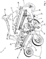
- reference number 1 overall indicates a mulching machine for laying a covering cloth over a ground to be covered. More in detail, the mulching machine 1, object of the present invention, is adapted to lay on the ground at least one strip 7 of a covering cloth 4 so as to execute operations of mulching of the ground itself.
- the aforesaid mulching machine is advantageously employed for laying covering cloths 4 over farming terrain to be cultivated, for example before executing sowing operations.
- the covering cloth 4 is susceptible of preventing the growth of weeds that can damage the growth of the cultivations to be sown on the farming terrain.
- the covering cloth 4 is susceptible of protecting the ground from external agents and maintaining the properties thereof without requiring further treatments.
- the mulching machine 1 is also susceptible of advancing along the ground to be covered, for example towed by a tractor or in a self-propelled manner. In the latter case the mulching machine 1 is thus provided with its own locomotion means.
- the mulching machine 1 object of the present invention, is susceptible of advancing on the ground along an advancement direction X, and in particular it is susceptible of advancing in an advancing sense V (indicated with an arrow in the enclosed figures 9 and 10 ) along the aforesaid advancement direction X.
- the mulching machine 1 comprises a support frame 2 susceptible of advancing on the ground along the advancement direction X, e.g. towed by a tractor or in a self-propelled manner.
- the mulching machine 1 is intended to be towed by the tractor (not illustrated), advantageously in fact the support frame 2 is provided with coupling points 25 arranged at a front portion of the support frame 2 and at which the tractor is susceptible of being attached.
- the aforesaid coupling points 25 are of three-point attachment type, per se known to the man skilled in the art and therefore not described in detail hereinbelow.
- the support frame 2 of the mulching machine 1 comprises a front crosspiece 28 and a rear crosspiece 29, substantially parallel to each other and each placed along an axis substantially orthogonal with respect to the advancement direction X of the mulching machine 1 itself, and in particular along a substantially horizontal direction.
- the support frame 2 advantageously comprises two lateral flanks 30 placed to mechanically connect between the front crosspiece 28 and the rear crosspiece 29.
- the support frame 2 is made of metallic material, in particular a metallic material that is resistant to the stresses to which the support frame 2 is intended to be subjected during its operating lifetime, such as for example steel.
- the mulching machine 1 also comprises at least one reel 3 of the covering cloth 4 intended to be laid on the ground.
- the covering cloth 4 is advantageously of the type commonly intended for ground mulching operations, for example it is a cloth made of plastic or bioplastic material and is preferably provided with a thickness comprised between 10 and 50 micron and more preferably comprised between 15 and 30 micron.
- the reel 3 is also rotatably associated with the support frame 2 by means of support means 5.
- the reel 3 is supported by the support means 5 in a position raised from the ground and preferably it is supported with a main extension axis Y thereof substantially parallel to the ground and preferably orthogonal to the advancement direction X.
- the support means 5 of the reel 3 advantageously comprise a pair of support brackets, each of which extended between a first end, pivoted to a corresponding lateral flank 30 of the support frame 2, and an opposite second end on which the reel 3 is rotatably mounted.
- the mulching machine 1, object of the present invention also comprises laying means 6 mechanically associated with the support frame 2 and interposed between the reel 3 and the ground.
- the aforesaid laying means 6 are adapted to unroll the strip 7 of covering cloth 4 from the reel 3 and to lay such strip 7 on the ground.
- the laying means 6 are adapted to guide the covering cloth 4 from the reel 3 to the ground. In this manner, therefore, the strip 7 of covering cloth 4 is laid on the ground on the rear part of the mulching machine 1.
- the laying means 6 comprise a first pair of idle wheels 26 mounted on the two lateral flanks 30 of the support frame 2 and susceptible of rotating via rolling friction with the ground during the advancing of the mulching machine 1.
- the support means 5 are advantageously adapted to support the reel 3 in abutment against the first pair of idle wheels 26 of the laying means 6.
- the first pair of idle wheels 26 tangentially intercepts the reel 3, bringing it into rotation by means of rolling friction.
- the first pair of idle wheels 26 also forces the covering cloth 4 to be unwound from the reel 3, and drives it in rotation around an external surface thereof up to intercepting the ground, on which the cloth is deposited.
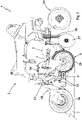
- the present mulching machine 1 also comprises earthing up means 8 mechanically associated with the support frame 2 and adapted to at least partially bury the strip 7 of covering cloth 4 laid on the ground. More in detail, the aforesaid earthing up means 8 are adapted to turn over the ground in proximity to the strip 7 so as to at least partially bury such strip 7 in order to retain it in position. In particular, in addition, the earthing up means 8 are adapted to turn over the ground in proximity to an initial end 7' and a final end 7" of the strip 7 with respect to the advancement direction X, as is better described hereinbelow in the description of a method for operating the present mulching machine 1.
- the aforesaid earthing up means 8 comprise a roller 9, rotatably associated with the support frame 2 and provided with a rotation axis Z placed substantially parallel to the ground and substantially orthogonal to the advancement direction X.
- the roller 9 is mounted on the support frame 2 on the rear part with respect to the laying means 6, so as to allow the earthing up means 8 to operate on the strip 7 of covering cloth 4 when the same cloth 7 is laid in abutment against the ground.
- the earthing up means 8 act on the strip 7 just laid on the ground and turn over the ground in proximity to the cloth 7 substantially along the entire extension thereof (i.e. along the entire width of the cloth) at the first and second ends 7', 7" of the strip 7.
- the roller 9 is rotatably mounted on a movable frame 18, which is in turn mechanically associated with the support frame 2, as is described more in detail hereinbelow.
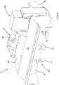
- the earthing up means 8 comprise a plurality of teeth 10 mechanically connected to the roller 9 and projecting outside the latter radially with respect to its rotation axis Z.
- the teeth 10 are preferably removably fixed to the roller 9 by means of removable fixing means 21, better described hereinbelow.
- the present mulching machine 1 comprises first movement means 13, placed to mechanically connect between the support frame 2 and the roller 9.
- the aforesaid first movement means 13 are adapted to move the roller 9, and in particular the movable frame 18 on which the roller 9 itself is mounted, between an interference position, in which the roller 9 is in a distal position with respect to the support frame 2 and at least one of the teeth 10 is susceptible of intercepting the ground, and a non-interference position, in which the roller 9 is in a proximal position with respect to the support frame 2 and the teeth 10 are susceptible of not intercepting the ground.
- the mulching machine 1 also comprises second movement means 14 mechanically associated with the roller 9 and adapted to rotate the latter around its rotation axis Z.
- the second movement means 14 are adapted to rotate the roller 9 alternately in a first rotation sense V1 and in a second rotation sense V2, opposite with respect to the first rotation sense V1.
- the second rotation sense V2 is in the same sense as the advancing sense V of the mulching machine 1, i.e. it is in the same sense as the rotation sense of the wheels of the tractor during its movement along the advancing sense V, and preferably it is in the same sense as the rotation sense of the first pair of idle wheels 26 of the laying means 6. Consequently, the first rotation sense V1 is in the opposite sense with respect to the advancing sense V of the present mulching machine 1.
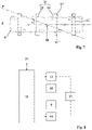
- the mulching machine 1 comprises a logic control unit 15 operatively connected to the first and to the second movement means 13, 14, for example as schematically illustrated in the enclosed figure 8 .
- the logic control unit 15 is advantageously connected to the first and to the second movement means 13, 14 by means of a data transmission electrical wiring, well known to the man skilled in the art and therefore not described in detail hereinbelow.
- the aforesaid logic control unit 15 is configured for driving the second movement means 14 to rotate the roller 9 in the two opposite rotation senses V1, V2, with the roller 9 in the interference position, in order to earth up the two opposite ends 7' ,7" of the strip 7 with the teeth 10 rotating in the two rotation senses V1, V2.
- the logic control unit 15 is advantageously configured for selecting the rotation sense V1, V2 along which the roller 9 is rotated, and hence also the teeth 10 are rotated.
- the teeth 10 which rotate in the two rotation senses V1, V2 intercept and turn over the ground, in order to at least partially bury the strip 7 of covering cloth 4 that was previously spread out on the ground.
- the teeth 10 In operation, by moving the roller 9 around its rotation axis Z in the aforesaid interference position, the teeth 10 intercept the ground and turn it over in order to lift a specific quantity of ground which is then left to fall at one between the first and second end 7', 7" of the strip 7, at least partially burying it.
- the teeth 10 of the earthing up means 8 advantageously intercept the strip 7 of the covering cloth 4, unwound and abutted against/spread out on the ground, and by rotating they hit and consequently cut it substantially transversely with respect to the advancement direction X of the mulching machine 1, separating the strip 7 laid on the ground from the reel 3.
- the teeth 10 execute a precise cutting of the strip 7, since such strip 7 was previously laid in abutment against the ground by the laying means 6.
- the roller 9 of the earthing up means 8 is attained in substantially cylindrical form and preferably in hollow cylindrical form. More in detail, the roller 9 is advantageously provided with a cylindrical perimeter wall extended around the rotation axis Z and preferably made of metallic material, such as steel.
- the cylindrical perimeter wall of the roller 9 is provided with a plurality of through slits 16, which are preferably distributed along the cylindrical perimeter wall, and in particular along two separate trajectories and substantially distributed as a double helix.
- each tooth 10 of the earthing up means 8 is preferably placed to traverse at least one corresponding through slit 16 and is advantageously removably fixed to the roller 9 by means of removable fixing means 21.
- each pair of through slits 16 comprises a first through slit 16' and a second through slit 16", advantageously facing the first through slit 16'.
- the first and the second slit 16', 16" of each pair of slits 16 are aligned along a specific diameter of a circular section of the cylindrical perimeter wall of the roller 9.
- each pair of slits 16 identifies a different diameter of the cylindrical perimeter wall.
- the different diameters along which the first and the second through slit 16', 16" of each pair of through slits 16 are aligned are also advantageously provided tilted with respect to each other, with respect to the rotation axis Z and preferably they are spaced from each other along the same rotation axis Z.
- the different diameters are provided equidistant from each other along the rotation axis Z and tilted by an angle comprised between 30° and 60°, and more preferably about 45°, with respect to the adjacent diameter.
- the first slits 16' define a first helical trajectory along the cylindrical perimeter wall and the second slits 16" define a second helical trajectory along the cylindrical perimeter wall, which in each point thereof is diametrically opposite with respect to every corresponding point of the first helical trajectory.
- the through slits 16 are advantageously distributed along the perimeter wall of the roller 9 as a double helix, in which the enveloping of the first through slits 16' of each pair constitutes a first helix and the enveloping of the second through slits 16" of each pair constitutes a second helix of the aforesaid double helix.
- each tooth 10 of the earthing up means 8 is extended along a diameter of the roller 9, to traverse the cylindrical perimeter wall thereof, and is inserted to traverse the two through slits 16 of a corresponding pair of through slits 16, and more in detail it is placed to traverse both the first and the second through slit 16', 16".
- the teeth 10 of the earthing up means 8 are advantageously provided equidistant from each other along the rotation axis Z of the roller 9 and additionally each tooth 10 is advantageously placed tilted with respect to the tooth 10 adjacent thereto, as indicated in the enclosed figure 6 .
- each tooth 10 of the earthing up means 8 is extended between two end portions 11, and is provided with an intermediate portion 12 placed to connect the two end portions 11.
- each of the two end portions 11 of each tooth 10 radially projects outside the roller 9, to traverse one of the two through slits 16 of a corresponding pair of through slits 16, and the intermediate portion 12 is placed to traverse the roller 9, substantially diametrically with respect to its cylindrical wall, between the aforesaid two through slits 16.
- each tooth 10 is advantageously provided with a first end portion 11' and with a second end portion 11", in which the first end portion 11' is placed projectingly beyond the first through slit 16' and the second end portion 11" is placed projectingly beyond the second through slit 16" of a corresponding pair of through slits 16.
- each end portion 11 of the teeth 10 of the earthing up means 8 is provided with a serrated edge 17, extended substantially transverse to the diameter of the roller 9 and intended to come into contact with the ground so as to turn it over.
- the serrated edge 17 of the end portions 11 of the teeth 10 is shaped in trident form so as to better absorb the impact with the ground, which generally has an irregular surface.
- each tooth 10 of the earthing up means 8 is made of substantially plate-like shape, i.e. it is provided with a main extension along a lying plane P.
- each tooth 10 is preferably made starting from a sheet made of metallic material, such as steel.
- the lying plane P of each tooth 10 passes through the rotation axis Z of the roller 9 and is tilted with respect to the latter, defining a tilt angle ⁇ between the lying plane P and the rotation axis Z.
- the lying plane P of each tooth 10 intersects the rotation axis Z in only one point and does not comprise the rotation axis Z itself.
- the tilt angle ⁇ between the lying plane P of each tooth 10 and the rotation axis Z of the roller 9 is comprised between 10° and 45° and preferably is about 20°, as illustrated for example in the enclosed figure 7 .
- each tooth 10 is during use susceptible of intercepting the ground, placed in a tilted manner with respect to the latter, and in particular it is susceptible of intercepting the ground with a limited portion of its serrated edge 17 so as to exert a greater pressure on the ground itself, in order to more easily turn it over.
- each tooth 10 is also susceptible of intercepting the strip 7 of covering cloth 4 placed in a tilted manner with respect to the latter, and in particular it is susceptible of intercepting the strip 7 with a limited portion of its serrated edge 17 so as to exert a greater pressure at such strip 7 in order to more easily break it.
- each tooth 10 is advantageously removably fixed to the roller 9 by means of suitable removable fixing means 21, which are preferably associated with each tooth 10 in proximity to at least one of the two through slits 16 through which the tooth 10 is inserted, and adapted to act as element for blocking the tooth 10 itself in order to prevent the latter from being removed from the through slit 16.
- the removable fixing means 21 thus make it advantageously possible to vary the number and the position of the teeth 10 fixed to the roller 9, so as to allow the earthing up means 8 to operate at pre-established zones. For example, it is possible to remove one or more teeth 10 from the roller 9 in order to prevent such teeth 10 from plunging into the ground at a specific ground zone, for example at which a small irrigation channel (not illustrated in the enclosed figures) is arranged which could be damaged by the teeth 10 of the earthing up means 8.
- the aforesaid removable fixing means 21 comprise at least one lateral shoulder 22, and preferably two lateral shoulders 22, laterally projecting from the first end portion 11' of each tooth 10 and placed in abutment against the cylindrical perimeter wall of the roller 9, blocking the tooth 10 in order to prevent the first end portion 11' from being inserted to traverse the first through slit 16'.
- the aforesaid lateral shoulders 22 are extended along the lying plane P of the tooth 10 and are preferably provided with a thickness substantially equal to the thickness of the first end portion 11', i.e. they are advantageously achieved starting from the steel sheet itself, from which also the tooth 10 is attained.
- the removable fixing means 21 advantageously comprise at least one bolt 23 associated with each tooth 10, preferably in proximity to the second through slit 16", placed outside and in abutment against the cylindrical wall of the roller 9 at the second slit 16" itself.
- Each bolt 23 is advantageously adapted to act as thickness of the tooth 10 in order to prevent its second end portion 11" from being removed from the second through slit 16".
- each bolt 23 of the removable fixing means 21 is provided with a screw, comprising a threaded stem placed to traverse a through hole made on the second end portion 11" of the tooth 10, and with a clamping nut, screwed to the threaded stem of the aforesaid screw.
- each tooth 10 is removably fixed to the roller 9, on one side, by means of the lateral shoulders 22 projecting laterally from the first end portion 11' and, on the other side, by means of the bolts 23 associated with the second end portion 11".
- each tooth 10 is susceptible of being associated with the roller 9 by inserting its second end portion 11" to traverse, in succession, the first and the second through slit 16', 16", up to bringing the lateral shoulders 22, laterally projecting from the first end portion 11', in abutment against the cylindrical perimeter wall of the roller 9 and subsequently by screwing the bolt 23 to the second end portion 11", which is projectingly placed outside the roller 9, beyond the second through slit 16".
- each tooth 10 is susceptible of being removed from the roller 9 by unscrewing the bolt 23 from the second end portion 11" and subsequently removing the second end portion 11" itself from the second and from the first through slits 16", 16'.
- the earthing up means 8 thus conceived are susceptible of being moved by the first and by the second movement means 13, 14 in order to at least partially bury the strip 7 of covering cloth 4 laid on the ground.
- the first movement means 13 are adapted to move the roller 9 between the interference position and the second portion, so as to bring the teeth 10 respectively to at least partially plunge into the ground and to be lifted from the latter.
- the first movement means 13 comprise the movable frame 18 which rotatably carries the roller 9 mounted thereon and which is in turn mechanically mounted on the support frame 2, preferably on the rear part with respect to the laying means 6.
- the movable frame 18 comprises at least one casing 31, extended around the roller 9 to partially cover the latter and provided with two lateral sides 32 on which the roller 9 is rotatably mounted.
- first movement means 13 advantageously comprise at least one articulated quadrilateral 19 placed to mechanically connect between the support frame 2 and the movable frame 18.
- first movement means 13 comprise two articulated quadrilaterals 19, each of which placed to mechanically connect between a lateral flank 30 of the support frame 2 and a corresponding lateral side 32 of the casing 31 of the movable frame 18.
- the first movement means 13 comprise at least one actuator 20, and preferably a linear actuator, operatively associated with the support frame 2 and with the movable frame 18 and adapted to act on the latter in order to move the roller 9 between the interference position and the non-interference position.
- the actuator 20 of the first movement means 13 preferably comprises a pneumatic piston slidably inserted in a containment cylinder, with respect to which the pneumatic piston is susceptible of sliding between an extended position, corresponding to the interference position of the roller 9, and a retracted position, corresponding to the non-interference position of the roller 9.
- the aforesaid actuator 20 is advantageously associated with an oil-pressure circuit, of the type known to the man skilled in the art and therefore not described in detail hereinbelow, which is advantageously actuated by electrical power supply means 27, e.g. connected to a power supply battery of the tractor to which the mulching machine 1 is fixed.
- the actuator 20 of the first movement means 13 can be of type different from that described above, without departing from the protective scope of the present patent.
- it can comprise a hydraulic piston or a screw engaged in a nut screw.
- the logic control unit 15 is operatively connected to the aforesaid first movement means 13.
- the logic control unit 15 is advantageously configured for varying the distance with respect to the support frame 2 in which the roller 9 of the earthing up means 8 is placed in the interference position.
- the logic control unit 15 is advantageously configured for varying the height with respect to the ground in which the roller 9 of the earthing up means 8 is placed in the interference position, so as to vary the depth with which the teeth 10 plunge into the ground and consequently vary the quantity of ground which is turned over by the earthing up means 8.
- the present mulching machine 1 also comprises a user interface 24 in data connection with the logic control unit 15 and through which it is possible, for an operator, to set the aforesaid height with respect to the ground in which the roller 9 of the earthing up means 8 is placed in the interference position.
- the operator through the user interface 24 it is possible for the operator to also select one from between the first and the second rotation sense V1, V2 in which the second movement means 14 rotate the roller 9 of the earthing up means 8. More in detail, as indicated above, the user interface 24 is in data connection with the logic control unit 15, which in turn is in data connection with the second movement means 14. In operation, therefore, through the user interface 24, the operator of the mulching machine 1 can select the rotation sense along which the roller 9 is moved so as to execute different earthing up operations.
- the second movement means 14 preferably comprise an electric motor, which is advantageously power supplied by the same electrical power supply means 27 which also power supply the actuator 20 of the first movement means 13.
- the aforesaid electric motor of the second movement means 14 is provided with a rotor, which is actuatable to rotate in the first and/or in the second rotation sense V1, V2 and is connected by means of a transmission belt to the roller 9 of the earthing up means 8, so as to rotate the aforesaid roller 9 in the same sense as its rotation sense.
- the second movement means 14 can also comprise a rotary actuator, different with respect to an electric motor, without departing from the protective scope of the present patent.
- the mulching machine 1 advantageously also comprises a position sensor, mechanically associated with the first movement means 13 and placed in data connection with the logic control unit 15.
- a position sensor is adapted to detect the position in which the first movement means 13 position the roller 9 and is configured for sending a first electrical signal to the logic control unit 15 containing the information of the position of the roller 9.
- the logic control unit 15 is then configured for analyzing the first electrical signal and for driving the second movement means 14 to rotate the roller 9 when the latter reaches in proximity to the interference position.
- the logic control unit 15 is configured for sending, to the second movement means 14, a second or a third electrical signal, in which the second electrical signal drives the second movement means 14 to rotate the roller 9 along the first rotation sense V1 and the third electrical signal drives the second movement means 14 to rotate the roller 9 along the second rotation sense V2.
- the operator can select which electrical signal to send from the logic control unit 15 to the second movement means 14 so as to select the first or the second rotation sense V1, V2 of the roller 9 of the earthing up means 8.
- the operator can also select the time interval along which the second movement means 14 actuate the roller 9.
- the logic control unit 15 can also comprise a clock, which is configured for controlling the duration of the time interval of actuation of the second movement means 14.
- the mulching machine 1 also comprises lateral earthing up means 33, which are mechanically associated with the support frame 2, preferably at its lateral flanks 30, and are adapted to at least partially bury the strip 7 of covering cloth 4 laid on the ground, in particular at two lateral edges thereof.
- the aforesaid lateral earthing up means 33 are mounted on the support frame 2 laterally with respect to the laying means 6 and preferably on the rear part with respect to the latter, in a manner so as to earth up the strip 7 with ground in an adjacent position with respect to the position in which the strip 7 itself comes into contact with the ground itself, executing a lateral earthing up of the strip 7.
- the lateral earthing up means 33 execute the aforesaid lateral earthing up immediately after the strip 7 has contacted the ground. In this manner, one prevents the strip 7 from being moved once laid on the ground by the laying means 6. In other words, therefore, the lateral earthing up means 33 laterally earth up the strip 7 of covering cloth 4 as soon as it is laid on the ground by the laying means 6.
- the lateral earthing up means 33 are mounted on the support frame 2 in a position interposed between the laying means 6 and earthing up means 8 that are described above.
- the earthing up means 8 are adapted to earth up the strip 7 after the latter has been laid on the ground by the laying means 6 and it has been at least partially retained in position on the ground by the lateral earthing up made by the lateral earthing up means 33. Consequently, the earthing up means 8 thus attained cut the strip 7 and precisely bury the first and the second ends 7', 7" of the strip 7, since the strip 7 is stopped on the ground by the lateral earthing up when the earthing up means 8 turn over the ground at the aforesaid ends 7', 7".
- the aforesaid lateral earthing up means 33 advantageously comprise a rotating cutter 34, and preferably two rotating cutters 34, each of which rotatably mounted on a first support rod 35 fixed to a corresponding lateral flank 30 of the support frame 2, in particular laterally with respect to the laying means 6.
- each first support rod 35 is fixed to the corresponding lateral flank 30 on the front part with respect to the position in which the movable frame 18 of the earthing up means 6 is fixed to the lateral flank 30 itself, as illustrated in figure 1 .
- each rotating cutter 34 is idly mounted on the corresponding first support rod 35 with its rotation axis placed substantially parallel to the ground and is susceptible of being rotated by the rolling friction with the ground.
- the lateral earthing up means 33 comprise third movement means (not illustrated in the enclosed figures) mechanically connected to each rotating cutter 34 and adapted to rotate the latter.
- each rotating cutter 34 of the lateral earthing up means 33 is adapted to turn over the ground laterally with respect to the strip 7 of covering cloth 4, burying one of its two lateral edges.
- each rotating cutter 34 is provided with a shaped edge, preferably serrated with star form, and more preferably provided with smoothed tips.
- the aforesaid shaped edge is particularly suitable for ploughing the ground, since it plunges into the ground with its own projecting portions, which turn over clumps of compact ground and move rigid bodies such as stones, roots or other elements.
- the rotating cutter 34 can also be attained in a different embodiment, without departing from the protective scope of the present patent.
- the present mulching machine 1 also comprises a second pair of idle wheels 36, which are rotatably associated with the mulching machine 1 on the rear part with respect to the rotating cutters 34 of the lateral earthing up means 33 and adapted to roll on the ground turned over by the lateral earthing up means 33 so as to flatten it, thus sealing the lateral earthing up of the strip 7 of covering cloth 4.
- each wheel of the second pair of idle wheels 36 is rotatably mounted on the movable frame 18 at one of the two lateral sides 32 of the casing 31.
- the present mulching machine 1 also comprises a pair of rotating discs 37, each of which rotatably and idly mounted on a second support rod 38 fixed to one of the lateral flanks 30 of the support frame 2 on the front part with respect to the laying means 6.
- each rotating disc 37 is susceptible of rotating via rolling friction with the ground, excavating a furrow in the ground itself, substantially parallel to the advancement direction X of the mulching machine 1.
- each rotating disc 37 is mounted on the mulching machine 1 at the two lateral edges of the strip 7 of covering cloth 4 intended to be laid by the laying means 6, so as to excavate the furrow at a ground zone where the corresponding lateral edge of the strip 7 is intended to be laid.
- the strip 7 of covering cloth 4 is advantageously laid on the ground with its two lateral edges placed at a lower height with respect to the remaining strip 7.
- the mulching machine 1 can also be associated with further farming machinery, so as to execute further working of the same ground.
- the mulching machine 1 advantageously comprises a convex shaping group 39, mechanically associated with the support frame 2 on the front part with respect to the laying means 6 and adapted to execute a convex shaping of the ground before laying the strip 7 of covering cloth 4.
- the mulching machine 1 can advantageously also comprise a sowing group (not illustrated in the enclosed figures), mechanically associated with the support frame 2 on the rear part with respect to the earthing up means 8 and adapted to perforate the strip 7 of covering cloth 4 and to deposit one or more seeds on the underlying ground.
- a sowing group (not illustrated in the enclosed figures), mechanically associated with the support frame 2 on the rear part with respect to the earthing up means 8 and adapted to perforate the strip 7 of covering cloth 4 and to deposit one or more seeds on the underlying ground.
- the mulching machine 1 can also comprise means for supporting and laying a small irrigation channel (also not illustrated in the enclosed figures), which are mechanically associated with the support frame 2 on the front part with respect to the laying means 6 and are adapted to lay the small irrigation channel before the strip 7 of covering cloth 4 so as to cover such small irrigation channel with the strip 7 itself.
- a small irrigation channel also not illustrated in the enclosed figures
- the method for operating the mulching machine 1 comprises a first step of laying an initial end 7' of the strip 7 of covering cloth 4.
- the laying means 6 unroll the covering cloth 4 from the reel 3 and lay at least the initial end 7' of the strip 7 on the ground.
- the initial end 7' of the strip 7 of covering cloth 4 is interposed between the ground and the earthing up means 8.
- the support means 5 support the reel 3 in abutment against the idle wheels 26, and during the aforesaid first laying step such idle wheels 26 rotate the reel 3, unrolling the strip 7 of covering cloth 4.
- idle wheels 26 accompany the strip 7 between the reel 3 and the ground and set it on the latter.
- the present method then comprises a first step for earthing up the initial end 7' of the strip 7 of covering cloth 4.
- first earthing up step the roller 9 of the earthing up means 8 is placed in the interference position and the logic control unit 15 drives the second movement means 14 to rotate the roller 9 in the first rotation sense V1.
- the teeth 10 of the earthing up means 8 also rotate along the first rotation sense V1, intercept the ground, turn it over and bury the initial end 7' of the strip 7 of covering cloth 4.
- the operator of the mulching machine 1 actuates the logic control unit 15, for example by means of the user interface 24.
- the logic control unit 15 then drives the first movement means 13 to position the roller 9 in the interference position, in particular at a height from the ground established by the operator.
- the position sensor sends the first electrical signal to the logic control unit 15 and, when the roller 9 reaches in proximity to the interference position, the logic control unit 15 sends the second electrical signal to the second movement means 14 which rotate the roller 9 along the first rotation sense V1.
- the teeth 10 of the earthing up means 8 by rotating along the first rotation sense V1 are adapted to turn over the ground and to lift it towards a front portion of the mulching machine 1, i.e. they are adapted to lift the ground towards the initial end 7' of the strip 7 of covering cloth 4, which is buried.
- the present method comprises a step of advancing the mulching machine 1 and of laying the strip 7 of covering cloth 4 on the ground, in which the strip 7 is laid interposed between the roller 9 of the earthing up means 8 and the ground.
- the mulching machine 1 is moved along the advancement direction X, e.g. towed by a tractor, and the first pair of idle wheels 26 rotates the reel 3, unrolling it and laying the strip 7 of covering cloth 4 on the ground.
- the present method comprises a step of lateral earthing up of the strip 7 of the covering cloth 4 laid on the ground by the laying means 6, in which the lateral earthing up means 33 turn over the ground laterally with respect to the strip 7 and at least partially bury the two lateral edges of the strip 7 itself.
- the rotating cutter 34 of the lateral earthing up means 33 rotates, turning over the ground laterally with respect to the strip 7 and buries the lateral edge of the latter, just laid on the ground.
- the aforesaid lateral earthing up step occurs immediately after the strip 7 of the covering cloth 4 is laid on the ground by the laying means 6.
- the aforesaid lateral earthing up step occurs substantially during the entire advancing of the machine 1 and in particular starts immediately after the first step of laying the initial end 7' of the cloth 7, in order to laterally earth up the entire length of the cloth 7 laid on the ground.
- the first earthing up step occurs subsequent to the start of the lateral earthing up step and the earthing up means 8 earth up the initial end 7' of the strip 7 laid on the ground and already laterally earthed up by the aforesaid lateral earthing up step.
- the strip 7 is already stably stopped on the ground by the lateral earthing up operations so as to be able to achieve the earthing up of the initial end 7' without the latter being moved during the earthing up action.
- the earthing up means 8 turn over the ground substantially at the aforesaid initial end 7', substantially burying it for the entire extension thereof (i.e. for the entire width of the strip 7) when the strip 7 is stably stopped on the ground by the lateral earthing up.
- the present method comprises a step of cutting the strip 7 of said covering cloth 4 forming a final end 7" of the strip 7 itself, opposite the initial end 7'.
- the first movement means 13 move the roller 9 of the earthing up means 8 into the interference position and at least one of the teeth 10 intercepts the strip 7 of covering cloth 4 and cuts it.
- the teeth 10 are susceptible of intercepting the strip 7 of covering cloth 4 laid on the ground and subsequently are susceptible of further advancing in order to at least partially plunge into the ground, thus breaking the strip 7.
- the strip 7 of the covering cloth results already laid on the ground by the laying means 6 and preferably is also well-fixed on the ground itself by the lateral earthing up.
- the teeth 10 precisely cut the strip 7 that is spread out well and fixed on the ground.
- the present method also comprises a second step for earthing up the final end 7".
- the roller 9 of the earthing up means 8 is placed in the interference position and the logic control unit 15 drives the second movement means 14 to rotate the roller 9 of the earthing up means 8 in the second rotation sense V2, opposite with respect to the first rotation sense V1.
- the teeth 10 of the earthing up means 8 also rotate along the second rotation sense V2, intercept the ground, turn it over and bury the final end 7" of the strip 7 of covering cloth 4.
- the cutting step and the second earthing up step substantially occur simultaneously and the roller 9 of the earthing up means 8 is rotated along the second rotation sense V2 before the teeth 10 intercept the strip 7 of covering cloth 4.
- the operator of the mulching machine 1 actuates the logic control unit 15, for example by means of the user interface 24.
- the logic control unit 15 drives the first movement means 13 to position the roller 9 in the interference position, in particular at a height from the ground established by the operator.
- the position sensor sends the first electrical signal to the logic control unit 15 and, when the roller 9 reaches in proximity to the interference position, the logic control unit 15 sends the third electrical signal to the second movement means 14 which rotate the roller 9 along the second rotation sense V2.
- the teeth 10 of the earthing up means 8 by rotating along the second rotation sense V2 are adapted to turn over the ground and to lift it towards a rear portion of the mulching machine 1, i.e. they are adapted to lift the ground towards the final end 7" of the strip 7 of covering cloth 4, which is then buried by the earthing up means 8.
- such second earthing up step occurs in an extremely precise manner, with the earthing up means 8 which substantially earth up the entire final end 7" in the strip 7, i.e. its entire width.
- the earthing up means 8 which substantially earth up the entire final end 7" in the strip 7, i.e. its entire width.
- the present method comprises at least one step of lifting the earthing up means 8, preferably provided between the first earthing up step and the advancing step. More in detail, in the aforesaid lifting step, the movement means 13 move the roller 9 towards the non-interference position, and the logic control unit 15 drives the second movement means 14 to stop the rotation of the roller 9 itself.
- the present method also comprises the aforesaid lifting step after the second earthing up step.
- the roller 9 of the earthing up means 8 is positioned in the interference position only at the first and second earthing up step.
- the teeth 10 of the earthing up means 8 are susceptible of being lifted from the ground when the earthing up means 8 themselves are not executing earthing up steps.
- the logic control unit 15 is configured for automatically driving the first and the second movement means 13, 14 to execute the aforesaid lifting step after a pre-established time interval from the start of the first or of the second earthing up step.
- the aforesaid first and second earthing up steps and the cutting step are executed with the mulching machine 1 stopped, i.e. with the mulching machine which is not moved along the advancement direction X.
- the first and the second earthing up are executed exactly at the initial end and final end 7', 7" of the strip 7 of covering cloth 4.
- the mulching machine 1 and its operating method thus conceived therefore attain the pre-established objects and in particular allow executing an automatic mulching of the ground, without requiring the operator to manually execute the steps of earthing up the initial end 7' or the final end 7" of the laid strip 7 of covering cloth 4.
Landscapes
- Health & Medical Sciences (AREA)
- General Health & Medical Sciences (AREA)
- Toxicology (AREA)
- Life Sciences & Earth Sciences (AREA)
- Environmental Sciences (AREA)
- Protection Of Plants (AREA)
- Soil Working Implements (AREA)
Applications Claiming Priority (1)
| Application Number | Priority Date | Filing Date | Title |
|---|---|---|---|
| IT102019000011169A IT201900011169A1 (it) | 2019-07-08 | 2019-07-08 | Macchina pacciamatrice per la stesura di un telo di copertura su un terreno e metodo di funzionamento di detta macchina |
Publications (2)
| Publication Number | Publication Date |
|---|---|
| EP3763201A1 EP3763201A1 (en) | 2021-01-13 |
| EP3763201B1 true EP3763201B1 (en) | 2022-05-11 |
Family
ID=68582120
Family Applications (1)
| Application Number | Title | Priority Date | Filing Date |
|---|---|---|---|
| EP20184649.0A Active EP3763201B1 (en) | 2019-07-08 | 2020-07-08 | Mulching machine for laying covering cloth over a ground and method for operating said machine |
Country Status (5)
| Country | Link |
|---|---|
| EP (1) | EP3763201B1 (pl) |
| ES (1) | ES2923699T3 (pl) |
| IT (1) | IT201900011169A1 (pl) |
| PL (1) | PL3763201T3 (pl) |
| PT (1) | PT3763201T (pl) |
Families Citing this family (1)
| Publication number | Priority date | Publication date | Assignee | Title |
|---|---|---|---|---|
| CN118355825B (zh) * | 2024-05-17 | 2024-11-05 | 武汉华天园林集团有限公司 | 一种矿山生态修复用植被网铺设装置 |
Family Cites Families (4)
| Publication number | Priority date | Publication date | Assignee | Title |
|---|---|---|---|---|
| WO2012061918A1 (en) * | 2010-11-08 | 2012-05-18 | Epi Environmental Technologies (Nevada) Inc. | Machine and method for laying and anchoring a sheet of material on a ground surface |
| FR2988560B1 (fr) * | 2012-03-30 | 2015-03-27 | Gerard Jaulent | Dispositif de pose d'un film plastique pour paillage |
| KR101791382B1 (ko) * | 2017-03-24 | 2017-10-30 | 윤병운 | 비닐 피복기용 비닐 컷팅장치 |
| CN107624290A (zh) * | 2017-10-27 | 2018-01-26 | 朴万寿 | 覆土铺膜直播机 |
-
2019
- 2019-07-08 IT IT102019000011169A patent/IT201900011169A1/it unknown
-
2020
- 2020-07-08 PL PL20184649.0T patent/PL3763201T3/pl unknown
- 2020-07-08 ES ES20184649T patent/ES2923699T3/es active Active
- 2020-07-08 EP EP20184649.0A patent/EP3763201B1/en active Active
- 2020-07-08 PT PT201846490T patent/PT3763201T/pt unknown
Also Published As
| Publication number | Publication date |
|---|---|
| PT3763201T (pt) | 2022-07-22 |
| ES2923699T3 (es) | 2022-09-29 |
| EP3763201A1 (en) | 2021-01-13 |
| PL3763201T3 (pl) | 2022-11-07 |
| IT201900011169A1 (it) | 2021-01-08 |
Similar Documents
| Publication | Publication Date | Title |
|---|---|---|
| CN110278729B (zh) | 全自动移栽联合作业机 | |
| EP0178081B1 (en) | Sod laying machine and method | |
| EP2342963B1 (en) | Method of applying input to an agricultural field | |
| EP0573620B1 (en) | Apparatus for laying turf | |
| US2882977A (en) | Gardening machine | |
| DE202012012728U1 (de) | Vorrichtung zum Schneiden von Kunstrasen | |
| EP3763201B1 (en) | Mulching machine for laying covering cloth over a ground and method for operating said machine | |
| US9326459B2 (en) | Machine for automatically pulling out the cut-off vine branches | |
| EP0487968B1 (de) | Bodenbearbeitungsmaschine | |
| KR101558217B1 (ko) | 땅속뿌리 작물의 줄기 제거장치 | |
| EP2092816B1 (de) | Mulchkopf | |
| JP6733113B2 (ja) | マルチ移植機 | |
| EP2333164B1 (en) | Device for burying slender elements, such as cables, pipes, ropes, chains, ducts and the like | |
| DE60001074T2 (de) | Verfahren zum auflegen einer kunststofffolie oder dergleichen, insbesondere zum landwirtschaftlichen gebrauch | |
| KR20170025146A (ko) | 비닐 피복기용 비닐 절단기 | |
| US3840076A (en) | Implement guiding system for row crops | |
| CN205408434U (zh) | 一种自动仿形残膜捡拾机 | |
| EP3595434B1 (en) | Machine for and method of extracting vine branches | |
| DE4136327A1 (de) | Landwirtschaftliche maschine | |
| KR100809832B1 (ko) | 땅속작물 수확기 | |
| KR101703686B1 (ko) | 비닐 피복기 | |
| JP7012370B2 (ja) | 管理機及び圃場管理方法 | |
| JP4026067B2 (ja) | シーダーマルチャーの鎮圧ローラー及び鎮圧ローラー歯形成形方法。 | |
| JPH0529015Y2 (pl) | ||
| KR20190054231A (ko) | 비닐피복기 |
Legal Events
| Date | Code | Title | Description |
|---|---|---|---|
| PUAI | Public reference made under article 153(3) epc to a published international application that has entered the european phase |
Free format text: ORIGINAL CODE: 0009012 |
|
| STAA | Information on the status of an ep patent application or granted ep patent |
Free format text: STATUS: THE APPLICATION HAS BEEN PUBLISHED |
|
| AK | Designated contracting states |
Kind code of ref document: A1 Designated state(s): AL AT BE BG CH CY CZ DE DK EE ES FI FR GB GR HR HU IE IS IT LI LT LU LV MC MK MT NL NO PL PT RO RS SE SI SK SM TR |
|
| AX | Request for extension of the european patent |
Extension state: BA ME |
|
| STAA | Information on the status of an ep patent application or granted ep patent |
Free format text: STATUS: REQUEST FOR EXAMINATION WAS MADE |
|
| 17P | Request for examination filed |
Effective date: 20210713 |
|
| RBV | Designated contracting states (corrected) |
Designated state(s): AL AT BE BG CH CY CZ DE DK EE ES FI FR GB GR HR HU IE IS IT LI LT LU LV MC MK MT NL NO PL PT RO RS SE SI SK SM TR |
|
| GRAP | Despatch of communication of intention to grant a patent |
Free format text: ORIGINAL CODE: EPIDOSNIGR1 |
|
| STAA | Information on the status of an ep patent application or granted ep patent |
Free format text: STATUS: GRANT OF PATENT IS INTENDED |
|
| INTG | Intention to grant announced |
Effective date: 20211201 |
|
| RAP3 | Party data changed (applicant data changed or rights of an application transferred) |
Owner name: ROTER ITALIA S.R.L. |
|
| GRAS | Grant fee paid |
Free format text: ORIGINAL CODE: EPIDOSNIGR3 |
|
| GRAA | (expected) grant |
Free format text: ORIGINAL CODE: 0009210 |
|
| STAA | Information on the status of an ep patent application or granted ep patent |
Free format text: STATUS: THE PATENT HAS BEEN GRANTED |
|
| AK | Designated contracting states |
Kind code of ref document: B1 Designated state(s): AL AT BE BG CH CY CZ DE DK EE ES FI FR GB GR HR HU IE IS IT LI LT LU LV MC MK MT NL NO PL PT RO RS SE SI SK SM TR |
|
| REG | Reference to a national code |
Ref country code: GB Ref legal event code: FG4D |
|
| REG | Reference to a national code |
Ref country code: CH Ref legal event code: EP |
|
| REG | Reference to a national code |
Ref country code: AT Ref legal event code: REF Ref document number: 1490607 Country of ref document: AT Kind code of ref document: T Effective date: 20220515 |
|
| REG | Reference to a national code |
Ref country code: DE Ref legal event code: R096 Ref document number: 602020003140 Country of ref document: DE |
|
| REG | Reference to a national code |
Ref country code: IE Ref legal event code: FG4D |
|
| REG | Reference to a national code |
Ref country code: PT Ref legal event code: SC4A Ref document number: 3763201 Country of ref document: PT Date of ref document: 20220722 Kind code of ref document: T Free format text: AVAILABILITY OF NATIONAL TRANSLATION Effective date: 20220718 |
|
| REG | Reference to a national code |
Ref country code: NL Ref legal event code: FP |
|
| REG | Reference to a national code |
Ref country code: LT Ref legal event code: MG9D |
|
| REG | Reference to a national code |
Ref country code: ES Ref legal event code: FG2A Ref document number: 2923699 Country of ref document: ES Kind code of ref document: T3 Effective date: 20220929 |
|
| PG25 | Lapsed in a contracting state [announced via postgrant information from national office to epo] |
Ref country code: SE Free format text: LAPSE BECAUSE OF FAILURE TO SUBMIT A TRANSLATION OF THE DESCRIPTION OR TO PAY THE FEE WITHIN THE PRESCRIBED TIME-LIMIT Effective date: 20220511 Ref country code: NO Free format text: LAPSE BECAUSE OF FAILURE TO SUBMIT A TRANSLATION OF THE DESCRIPTION OR TO PAY THE FEE WITHIN THE PRESCRIBED TIME-LIMIT Effective date: 20220811 Ref country code: LT Free format text: LAPSE BECAUSE OF FAILURE TO SUBMIT A TRANSLATION OF THE DESCRIPTION OR TO PAY THE FEE WITHIN THE PRESCRIBED TIME-LIMIT Effective date: 20220511 Ref country code: HR Free format text: LAPSE BECAUSE OF FAILURE TO SUBMIT A TRANSLATION OF THE DESCRIPTION OR TO PAY THE FEE WITHIN THE PRESCRIBED TIME-LIMIT Effective date: 20220511 Ref country code: GR Free format text: LAPSE BECAUSE OF FAILURE TO SUBMIT A TRANSLATION OF THE DESCRIPTION OR TO PAY THE FEE WITHIN THE PRESCRIBED TIME-LIMIT Effective date: 20220812 Ref country code: FI Free format text: LAPSE BECAUSE OF FAILURE TO SUBMIT A TRANSLATION OF THE DESCRIPTION OR TO PAY THE FEE WITHIN THE PRESCRIBED TIME-LIMIT Effective date: 20220511 Ref country code: BG Free format text: LAPSE BECAUSE OF FAILURE TO SUBMIT A TRANSLATION OF THE DESCRIPTION OR TO PAY THE FEE WITHIN THE PRESCRIBED TIME-LIMIT Effective date: 20220811 |
|
| PG25 | Lapsed in a contracting state [announced via postgrant information from national office to epo] |
Ref country code: RS Free format text: LAPSE BECAUSE OF FAILURE TO SUBMIT A TRANSLATION OF THE DESCRIPTION OR TO PAY THE FEE WITHIN THE PRESCRIBED TIME-LIMIT Effective date: 20220511 Ref country code: LV Free format text: LAPSE BECAUSE OF FAILURE TO SUBMIT A TRANSLATION OF THE DESCRIPTION OR TO PAY THE FEE WITHIN THE PRESCRIBED TIME-LIMIT Effective date: 20220511 Ref country code: IS Free format text: LAPSE BECAUSE OF FAILURE TO SUBMIT A TRANSLATION OF THE DESCRIPTION OR TO PAY THE FEE WITHIN THE PRESCRIBED TIME-LIMIT Effective date: 20220911 |
|
| PG25 | Lapsed in a contracting state [announced via postgrant information from national office to epo] |
Ref country code: SM Free format text: LAPSE BECAUSE OF FAILURE TO SUBMIT A TRANSLATION OF THE DESCRIPTION OR TO PAY THE FEE WITHIN THE PRESCRIBED TIME-LIMIT Effective date: 20220511 Ref country code: SK Free format text: LAPSE BECAUSE OF FAILURE TO SUBMIT A TRANSLATION OF THE DESCRIPTION OR TO PAY THE FEE WITHIN THE PRESCRIBED TIME-LIMIT Effective date: 20220511 Ref country code: RO Free format text: LAPSE BECAUSE OF FAILURE TO SUBMIT A TRANSLATION OF THE DESCRIPTION OR TO PAY THE FEE WITHIN THE PRESCRIBED TIME-LIMIT Effective date: 20220511 Ref country code: EE Free format text: LAPSE BECAUSE OF FAILURE TO SUBMIT A TRANSLATION OF THE DESCRIPTION OR TO PAY THE FEE WITHIN THE PRESCRIBED TIME-LIMIT Effective date: 20220511 Ref country code: DK Free format text: LAPSE BECAUSE OF FAILURE TO SUBMIT A TRANSLATION OF THE DESCRIPTION OR TO PAY THE FEE WITHIN THE PRESCRIBED TIME-LIMIT Effective date: 20220511 Ref country code: CZ Free format text: LAPSE BECAUSE OF FAILURE TO SUBMIT A TRANSLATION OF THE DESCRIPTION OR TO PAY THE FEE WITHIN THE PRESCRIBED TIME-LIMIT Effective date: 20220511 |
|
| REG | Reference to a national code |
Ref country code: DE Ref legal event code: R097 Ref document number: 602020003140 Country of ref document: DE |
|
| PG25 | Lapsed in a contracting state [announced via postgrant information from national office to epo] |
Ref country code: MC Free format text: LAPSE BECAUSE OF FAILURE TO SUBMIT A TRANSLATION OF THE DESCRIPTION OR TO PAY THE FEE WITHIN THE PRESCRIBED TIME-LIMIT Effective date: 20220511 |
|
| REG | Reference to a national code |
Ref country code: AT Ref legal event code: UEP Ref document number: 1490607 Country of ref document: AT Kind code of ref document: T Effective date: 20220511 |
|
| PLBE | No opposition filed within time limit |
Free format text: ORIGINAL CODE: 0009261 |
|
| STAA | Information on the status of an ep patent application or granted ep patent |
Free format text: STATUS: NO OPPOSITION FILED WITHIN TIME LIMIT |
|
| REG | Reference to a national code |
Ref country code: BE Ref legal event code: MM Effective date: 20220731 |
|
| PG25 | Lapsed in a contracting state [announced via postgrant information from national office to epo] |
Ref country code: AL Free format text: LAPSE BECAUSE OF FAILURE TO SUBMIT A TRANSLATION OF THE DESCRIPTION OR TO PAY THE FEE WITHIN THE PRESCRIBED TIME-LIMIT Effective date: 20220511 |
|
| 26N | No opposition filed |
Effective date: 20230214 |
|
| PG25 | Lapsed in a contracting state [announced via postgrant information from national office to epo] |
Ref country code: LU Free format text: LAPSE BECAUSE OF NON-PAYMENT OF DUE FEES Effective date: 20220708 |
|
| PG25 | Lapsed in a contracting state [announced via postgrant information from national office to epo] |
Ref country code: SI Free format text: LAPSE BECAUSE OF FAILURE TO SUBMIT A TRANSLATION OF THE DESCRIPTION OR TO PAY THE FEE WITHIN THE PRESCRIBED TIME-LIMIT Effective date: 20220511 Ref country code: BE Free format text: LAPSE BECAUSE OF NON-PAYMENT OF DUE FEES Effective date: 20220731 |
|
| P01 | Opt-out of the competence of the unified patent court (upc) registered |
Effective date: 20230321 |
|
| PG25 | Lapsed in a contracting state [announced via postgrant information from national office to epo] |
Ref country code: IE Free format text: LAPSE BECAUSE OF NON-PAYMENT OF DUE FEES Effective date: 20220708 |
|
| REG | Reference to a national code |
Ref country code: CH Ref legal event code: PL |
|
| PG25 | Lapsed in a contracting state [announced via postgrant information from national office to epo] |
Ref country code: MK Free format text: LAPSE BECAUSE OF FAILURE TO SUBMIT A TRANSLATION OF THE DESCRIPTION OR TO PAY THE FEE WITHIN THE PRESCRIBED TIME-LIMIT Effective date: 20220511 Ref country code: CY Free format text: LAPSE BECAUSE OF FAILURE TO SUBMIT A TRANSLATION OF THE DESCRIPTION OR TO PAY THE FEE WITHIN THE PRESCRIBED TIME-LIMIT Effective date: 20220511 Ref country code: CH Free format text: LAPSE BECAUSE OF NON-PAYMENT OF DUE FEES Effective date: 20230731 |
|
| PG25 | Lapsed in a contracting state [announced via postgrant information from national office to epo] |
Ref country code: HU Free format text: LAPSE BECAUSE OF FAILURE TO SUBMIT A TRANSLATION OF THE DESCRIPTION OR TO PAY THE FEE WITHIN THE PRESCRIBED TIME-LIMIT; INVALID AB INITIO Effective date: 20200708 |
|
| PG25 | Lapsed in a contracting state [announced via postgrant information from national office to epo] |
Ref country code: TR Free format text: LAPSE BECAUSE OF FAILURE TO SUBMIT A TRANSLATION OF THE DESCRIPTION OR TO PAY THE FEE WITHIN THE PRESCRIBED TIME-LIMIT Effective date: 20220511 |
|
| PG25 | Lapsed in a contracting state [announced via postgrant information from national office to epo] |
Ref country code: MT Free format text: LAPSE BECAUSE OF FAILURE TO SUBMIT A TRANSLATION OF THE DESCRIPTION OR TO PAY THE FEE WITHIN THE PRESCRIBED TIME-LIMIT Effective date: 20220511 |
|
| PG25 | Lapsed in a contracting state [announced via postgrant information from national office to epo] |
Ref country code: BG Free format text: LAPSE BECAUSE OF FAILURE TO SUBMIT A TRANSLATION OF THE DESCRIPTION OR TO PAY THE FEE WITHIN THE PRESCRIBED TIME-LIMIT Effective date: 20220511 |
|
| PG25 | Lapsed in a contracting state [announced via postgrant information from national office to epo] |
Ref country code: BG Free format text: LAPSE BECAUSE OF FAILURE TO SUBMIT A TRANSLATION OF THE DESCRIPTION OR TO PAY THE FEE WITHIN THE PRESCRIBED TIME-LIMIT Effective date: 20220511 |
|
| PGFP | Annual fee paid to national office [announced via postgrant information from national office to epo] |
Ref country code: PT Payment date: 20250626 Year of fee payment: 6 |
|
| PGFP | Annual fee paid to national office [announced via postgrant information from national office to epo] |
Ref country code: NL Payment date: 20250721 Year of fee payment: 6 |
|
| PGFP | Annual fee paid to national office [announced via postgrant information from national office to epo] |
Ref country code: ES Payment date: 20250827 Year of fee payment: 6 |
|
| PGFP | Annual fee paid to national office [announced via postgrant information from national office to epo] |
Ref country code: DE Payment date: 20250722 Year of fee payment: 6 |
|
| PGFP | Annual fee paid to national office [announced via postgrant information from national office to epo] |
Ref country code: IT Payment date: 20250724 Year of fee payment: 6 Ref country code: PL Payment date: 20250701 Year of fee payment: 6 |
|
| PGFP | Annual fee paid to national office [announced via postgrant information from national office to epo] |
Ref country code: GB Payment date: 20250722 Year of fee payment: 6 |
|
| PGFP | Annual fee paid to national office [announced via postgrant information from national office to epo] |
Ref country code: FR Payment date: 20250725 Year of fee payment: 6 Ref country code: AT Payment date: 20250722 Year of fee payment: 6 |