EP3763181B1 - Erntevorrichtung - Google Patents
Erntevorrichtung Download PDFInfo
- Publication number
- EP3763181B1 EP3763181B1 EP20185127.6A EP20185127A EP3763181B1 EP 3763181 B1 EP3763181 B1 EP 3763181B1 EP 20185127 A EP20185127 A EP 20185127A EP 3763181 B1 EP3763181 B1 EP 3763181B1
- Authority
- EP
- European Patent Office
- Prior art keywords
- overload protection
- harvesting
- pickup
- shiftable
- axis
- Prior art date
- Legal status (The legal status is an assumption and is not a legal conclusion. Google has not performed a legal analysis and makes no representation as to the accuracy of the status listed.)
- Active
Links
Images

Classifications
-
- A—HUMAN NECESSITIES
- A01—AGRICULTURE; FORESTRY; ANIMAL HUSBANDRY; HUNTING; TRAPPING; FISHING
- A01B—SOIL WORKING IN AGRICULTURE OR FORESTRY; PARTS, DETAILS, OR ACCESSORIES OF AGRICULTURAL MACHINES OR IMPLEMENTS, IN GENERAL
- A01B73/00—Means or arrangements to facilitate transportation of agricultural machines or implements, e.g. folding frames to reduce overall width
- A01B73/02—Folding frames
- A01B73/04—Folding frames foldable about a horizontal axis
- A01B73/044—Folding frames foldable about a horizontal axis the axis being oriented in a longitudinal direction
-
- A—HUMAN NECESSITIES
- A01—AGRICULTURE; FORESTRY; ANIMAL HUSBANDRY; HUNTING; TRAPPING; FISHING
- A01D—HARVESTING; MOWING
- A01D78/00—Haymakers with tines moving with respect to the machine
- A01D78/08—Haymakers with tines moving with respect to the machine with tine-carrying rotary heads or wheels
- A01D78/14—Haymakers with tines moving with respect to the machine with tine-carrying rotary heads or wheels the tines rotating about a substantially horizontal axis
- A01D78/142—Arrangements for transport by movement of the heads carrying rake arms
- A01D78/144—Arrangements for transport by movement of the heads carrying rake arms in a vertical plane
-
- A—HUMAN NECESSITIES
- A01—AGRICULTURE; FORESTRY; ANIMAL HUSBANDRY; HUNTING; TRAPPING; FISHING
- A01B—SOIL WORKING IN AGRICULTURE OR FORESTRY; PARTS, DETAILS, OR ACCESSORIES OF AGRICULTURAL MACHINES OR IMPLEMENTS, IN GENERAL
- A01B73/00—Means or arrangements to facilitate transportation of agricultural machines or implements, e.g. folding frames to reduce overall width
- A01B73/02—Folding frames
- A01B73/06—Folding frames foldable about a vertical axis
-
- A—HUMAN NECESSITIES
- A01—AGRICULTURE; FORESTRY; ANIMAL HUSBANDRY; HUNTING; TRAPPING; FISHING
- A01D—HARVESTING; MOWING
- A01D75/00—Accessories for harvesters or mowers
- A01D75/18—Safety devices for parts of the machines
- A01D75/182—Avoiding overload
-
- A—HUMAN NECESSITIES
- A01—AGRICULTURE; FORESTRY; ANIMAL HUSBANDRY; HUNTING; TRAPPING; FISHING
- A01D—HARVESTING; MOWING
- A01D75/00—Accessories for harvesters or mowers
- A01D75/18—Safety devices for parts of the machines
- A01D75/185—Avoiding collisions with obstacles
-
- A—HUMAN NECESSITIES
- A01—AGRICULTURE; FORESTRY; ANIMAL HUSBANDRY; HUNTING; TRAPPING; FISHING
- A01D—HARVESTING; MOWING
- A01D78/00—Haymakers with tines moving with respect to the machine
- A01D78/08—Haymakers with tines moving with respect to the machine with tine-carrying rotary heads or wheels
- A01D78/14—Haymakers with tines moving with respect to the machine with tine-carrying rotary heads or wheels the tines rotating about a substantially horizontal axis
- A01D78/142—Arrangements for transport by movement of the heads carrying rake arms
- A01D78/146—Arrangements for transport by movement of the heads carrying rake arms in a horizontal plane
-
- A—HUMAN NECESSITIES
- A01—AGRICULTURE; FORESTRY; ANIMAL HUSBANDRY; HUNTING; TRAPPING; FISHING
- A01D—HARVESTING; MOWING
- A01D84/00—Haymakers not provided for in a single one of groups A01D76/00 - A01D82/00
Definitions
- the invention relates to a harvesting device, namely a merger or pickup rake.
- a harvesting device designed as a merger is known. Mergers are also known as pickup swathers. According to this state of the art, the harvesting device designed as a merger has a support frame and a chassis. Furthermore, the harvesting device designed as a merger has pickup elements designed as a pickup for picking up the harvested material and cross conveyor devices designed as belt conveyors for cross-conveying the picked up harvested material.
- the support frame has a longitudinal beam and cross beams, with the pickup elements and cross conveyor devices being mounted on the cross beams.
- a merger which has receiving elements designed as a pickup and cross conveyor devices designed as belt conveyors, which can be moved between a working position and a transport position as required.
- the receiving elements and the cross conveyor devices are arranged by means of cross beams on both sides of a longitudinal beam, which has a chassis with wheels, and can be moved via horizontal axes from the essentially vertical transport position to an essentially horizontal intermediate position. From the intermediate position, the receiving elements and the cross conveyor devices can be moved to the working position via vertical axes.
- the merger or pick-up rake If the merger or pick-up rake hits an obstacle during harvesting and the obstacle exerts a force on the pickup elements and/or the cross conveyor devices that works against the direction of harvesting, the merger or pick-up rake can be damaged. This is a disadvantage. Up to now, it has been difficult to prevent such damage to a merger or pick-up rake. There is therefore a need for a harvesting device designed as a merger or pick-up rake, which reduces the risk of damage during harvesting as a result of obstacles that the harvesting device drives against or hits.
- the present invention is based on the object of creating a novel harvesting device designed as a merger or pickup rake.
- the harvesting device has a supporting frame with a longitudinal beam and cross beams.
- the harvesting device has a chassis with wheels.
- the harvesting device has receiving elements designed as pickups for receiving crops and cross-conveying devices designed as belt conveyors for conveying the picked-up crops in a cross-conveying direction running transversely to a longitudinal direction.
- a receiving element and a cross-conveying device are arranged on a first side and a second side of the longitudinal beam.
- a first displaceable cross member arranged on the respective side of the longitudinal member, receiving the respective receiving member and the respective transverse conveyor device, is displaceable about an axis extending in the vertical direction relative to a second displaceable cross member and further displaceable with the second displaceable cross member about an axis extending in the horizontal longitudinal direction relative to a fixed cross member engaging the longitudinal member.
- a respective first overload protection device is positioned between the first and second displaceable cross members arranged on the respective side of the longitudinal member, which is triggered when a force acting counter to the harvesting direction on the respective receiving element and/or the respective cross conveyor device and/or the respective first cross member exceeds a limit value and allows the respective receiving element and the respective cross conveyor device to be displaced rearwardly around the axis extending in the vertical direction in the opposite direction to the harvesting direction.
- the respective first overload protection device which is arranged on the respective side of the longitudinal member of the support frame between the respective first displaceable cross member of the support frame and the respective second displaceable cross member of the support frame, allows the receiving member arranged on the respective side and the respective cross conveyor device to deflect backwards in the opposite direction to the harvesting direction, about the axis extending in the vertical direction.
- the respective first overload protection device is triggered and allows the respective pickup element and the respective cross conveyor device to be moved backwards around the respective axis extending in the vertical direction. This significantly reduces the risk of damage to the pickup elements and cross conveyor devices of the harvesting device.
- the respective first overload protection device when the respective first overload protection device is triggered and allows the respective receiving element and the respective cross conveyor device to be moved backwards around the axis extending in the vertical direction in the opposite direction to the harvesting direction, the respective receiving element and the respective cross conveyor device are automatically also moved upwards around the axis extending in the horizontal longitudinal direction This is particularly preferred in order to further reduce the risk of damage to the receiving elements and cross conveyor devices.
- the receiving members and the cross conveyor devices can be automatically displaced upwards about the respective axis extending in the horizontal longitudinal direction, which is formed between the respective second, displaceable cross member and the respective fixed cross member.
- an actuator is positioned between the second movable cross member arranged on the respective side of the longitudinal member and the respective fixed cross member, which actuator automatically displaces the respective receiving element and the respective cross conveyor device upwards about the axis extending in the horizontal longitudinal direction when the respective first overload protection device is triggered.
- the respective cross conveyor device can be particularly preferably displaced upwards together with the respective receiving element via the actuator.
- the invention relates to a harvesting device designed as a merger.
- a harvesting device is also referred to as a pickup rake.
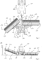
- Fig.1 and 2 show a harvesting device 10 in working position together with a towing vehicle 11.
- the harvesting device 10 has a support frame 12 with a longitudinal beam 13 and cross beams 14, 15, 16.
- the harvesting device 10 can be coupled to the towing vehicle 11 via the longitudinal beam 13, namely a coupling device 17 formed at the front end of the longitudinal beam 13, in order to be pulled by the towing vehicle 11 along a surface to be worked.
- the longitudinal beam 13 extends in the pulling direction or harvesting direction ER.
- the cross members 14, 15, 16 extend transversely or perpendicularly to the longitudinal member 13 and thus in the harvesting direction ER.
- the harvesting device 10 also has a chassis 18 with wheels 19.
- the chassis 18 is also referred to as the main chassis.
- the harvesting device 10, which is designed as a merger, is supported on the surface to be worked or driven on, both in the working position and in a transport position, via the wheels 19 of the chassis 18.
- the harvesting device 10 also has receiving elements 20 and cross conveyor devices 21.
- the pickup elements 20 are designed as so-called pickups and are used to pick up crops from the ground to be worked.
- a first pickup element 20 is mounted on a respective first cross member 14.
- a second pickup element 20 is mounted on the respective first cross member 14.
- the pickup elements 20 have pickup tines 22 which are driven about an axis extending in the transverse direction to pick up the crops from the ground. In the working position of the harvesting device 10, each of the pickup elements 20 is supported on the ground to be worked via feeler wheels 23.
- the harvesting device 10 has, in addition to the receiving elements 20, the cross conveyor devices 21.
- the cross conveyor devices 21 are designed as belt conveyors, wherein the cross conveyor devices 21 the crop picked up from the ground to be worked via the pick-up members 20 can be transported in a transverse conveying direction extending transversely or perpendicularly to the longitudinal direction.
- a first transverse conveying device 21 is received together with the respective pick-up device 20 on the respective first transverse beam 14.
- a second transverse conveying device 21 is received together with the respective pick-up device 20 on the respective first transverse beam 14.
- the cross conveyor devices 21 are arranged behind the receiving elements 20 when viewed in the harvesting direction ER.
- the first cross beams 14, on which the receiving elements 20 and the cross conveyor devices 21 are accommodated, can be displaced about an axis 24 extending in the vertical direction relative to a second cross beam 15.
- the second cross beams 15 can in turn be displaced about an axis 25 extending in the horizontal longitudinal direction to a third cross beam 16.
- the third cross beams 16 engage firmly on the longitudinal beam 13.
- a receiving element 20 and a transverse conveyor device 21 are arranged on each side of the longitudinal member 13.
- the first displaceable cross member 14 arranged on a respective side of the longitudinal member 13 receives the respective receiving member 20 and the respective cross conveyor device 21.
- the respective first displaceable cross member 14 is displaceable with the respective second displaceable cross member 15 about the axis 25 extending in the horizontal longitudinal direction relative to the respective fixed cross member 16, which engages the longitudinal member 13 in a non-displaceable manner.
- This displaceability about the The axis 25 extending in the horizontal longitudinal direction corresponds to a folding movement of the respective receiving element 20 and the respective cross conveyor device 21 upwards.
- a respective first overload protection device 26 is positioned between the first and second displaceable cross members 14 and 15 arranged on the respective side of the longitudinal member 13.
- This respective first overload protection device 26 of the harvesting device designed as a merger or pickup rake is triggered when a force acting against the harvesting direction ER on the respective receiving element 20 and/or the respective cross conveyor device 21 and/or the respective first cross member 14 is greater than a predetermined limit value.
- the triggered first overload protection device 26 then allows a displacement of the respective receiving member 20 and the respective cross conveyor device 21 together with the respective first displaceable cross member 14 about the axis 24 extending in the vertical direction to the rear in the opposite direction to the harvesting direction.
- the respective first overload protection device 26 is triggered and allows the automatic displacement of the respective receiving element 20 and the respective cross conveyor device 21 together with the respective first displaceable cross member 14 from the position shown in Fig.1 shown working position backwards against the harvesting direction ER, as shown in Fig. 2 for the receiving member 20 positioned on the left side of the longitudinal member 13 and the corresponding transverse conveyor device 21.
- Fig. 1 to 3 show possible obstacles 27, 28, which protrude at different heights in the vertical direction compared to the surface to be worked on.
- the respective first overload protection device 26 is an overload protection cylinder which automatically triggers or opens when the pressure acting in the cylinder exceeds a limit value.
- the respective first overload protection device 26 can also be an overload protection strut which mechanically yields along a predetermined breaking point.
- the respective receiving element 20 and the respective cross conveyor device 21 together with the respective first displaceable cross member 14 can also automatically be displaced upwards about the axis 25 extending in the horizontal longitudinal direction.
- the respective receiving element 20 together with the respective cross conveyor device 21 is then automatically displaced upwards when a force acting against the harvesting direction on the respective receiving element 20 and/or the respective cross conveyor device 21 and/or the respective cross member 14 is greater than a limit value.
- an actuator 29 is arranged between the second displaceable cross member 15 arranged on the respective side of the longitudinal member 13 and the respective fixed cross member 16, with which the respective second displaceable cross member 15 can be displaced relative to the respective fixed cross member 16 and thus also the respective first displaceable cross member 14 together with the receiving element 20 received on the same and the respective cross conveyor device 21 upwards about the axis 25 extending in the horizontal longitudinal direction.
- This actuator 29 is preferably an actuating cylinder, such as a hydraulic actuating cylinder.
- a second overload protection device 30 into this actuator 29, which is triggered when a force acting in the vertical direction on the respective receiving element 20 and/or the respective cross conveyor device 21 and/or the respective first or second cross member 14, 15 is greater than a limit value and then allows the respective receiving element 20 and the respective cross conveyor device 21 to be displaced upwards about the axis 25 extending in the horizontal longitudinal direction.
- the invention can be used to prevent a harvesting device designed as a merger or pick-up rake from being damaged when it comes into contact with an obstacle protruding from a surface to be worked and a force exerted thereby on a receiving member and/or a cross conveyor device and/or a cross member receiving the receiving member and the cross conveyor device.
- the respective first overload protection device 26 can only be triggered if the force acting opposite to the harvesting direction ER acts in a response range on the respective receiving member 20 and/or the respective cross conveyor device 21 and/or the cross member 14 receiving these assemblies, which lies between the respective vertical axis 24 and the respective lateral end of the harvesting device.
Landscapes
- Life Sciences & Earth Sciences (AREA)
- Environmental Sciences (AREA)
- Engineering & Computer Science (AREA)
- Mechanical Engineering (AREA)
- Soil Sciences (AREA)
- Harvester Elements (AREA)
- Chain Conveyers (AREA)
Priority Applications (1)
| Application Number | Priority Date | Filing Date | Title |
|---|---|---|---|
| SI202030531T SI3763181T1 (sl) | 2019-07-10 | 2020-07-10 | Žetvena naprava |
Applications Claiming Priority (1)
| Application Number | Priority Date | Filing Date | Title |
|---|---|---|---|
| DE102019118739.7A DE102019118739A1 (de) | 2019-07-10 | 2019-07-10 | Erntevorrichtung |
Publications (2)
| Publication Number | Publication Date |
|---|---|
| EP3763181A1 EP3763181A1 (de) | 2021-01-13 |
| EP3763181B1 true EP3763181B1 (de) | 2024-09-11 |
Family
ID=71575109
Family Applications (1)
| Application Number | Title | Priority Date | Filing Date |
|---|---|---|---|
| EP20185127.6A Active EP3763181B1 (de) | 2019-07-10 | 2020-07-10 | Erntevorrichtung |
Country Status (5)
| Country | Link |
|---|---|
| US (1) | US12089533B2 (pl) |
| EP (1) | EP3763181B1 (pl) |
| DE (1) | DE102019118739A1 (pl) |
| PL (1) | PL3763181T3 (pl) |
| SI (1) | SI3763181T1 (pl) |
Families Citing this family (2)
| Publication number | Priority date | Publication date | Assignee | Title |
|---|---|---|---|---|
| DE102020106803A1 (de) * | 2020-03-12 | 2021-09-16 | Claas Saulgau Gmbh | Erntevorrichtung |
| GR1010489B (el) * | 2022-06-24 | 2023-06-16 | Κωνσταντινος Ιωαννη Τσουντανης | Μεταδοση κινησης σε στελεχοκοπτη απο γκρουπ που τοποθετειται στην ακραια πλευρικη θεση του κελυφους και οχι σε ενδιαμεση με τα γκρουπ που κινουν τα μαχαιρια ή τις αλυσιδες, με δυνατοτητα μεγαλυτερης μετατοπισης του στελεχοκοπτη απο τον ελκυστηρα |
Family Cites Families (15)
| Publication number | Priority date | Publication date | Assignee | Title |
|---|---|---|---|---|
| FR2719189B1 (fr) * | 1994-04-29 | 1996-07-05 | Kuhn Sa | Faucheuse à dispositif de sécurité. |
| DE10234741A1 (de) * | 2002-07-30 | 2004-02-19 | Claas Saulgau Gmbh | Anlenkung eines Seitenmähwerks und seiner Zusatzeinrichtungen an ein Tragwerk zur Ankopplung an einen Traktor oder an ein Trägerfahrzeug |
| US7310929B2 (en) * | 2003-03-31 | 2007-12-25 | Oxbo International Corporation | Windrow merging apparatus |
| FR2865104B1 (fr) | 2004-01-19 | 2006-03-24 | Kuhn Sa | Faucheuse agricole munie d'un dispositif de convoyage pivotant autour d'un axe vertical |
| NL1032946C2 (nl) * | 2006-11-27 | 2008-05-28 | Maasland Nv | Bewerkingsinrichting. |
| DE102007053577A1 (de) * | 2007-11-09 | 2009-05-20 | Alois Pöttinger Maschinenfabrik Gmbh | Landmaschine |
| US8091331B2 (en) * | 2008-08-15 | 2012-01-10 | Oxbo International Corporation | Windrow merger |
| US8863489B2 (en) * | 2011-03-30 | 2014-10-21 | H & S Manufacturing Co., Inc. | Tine drive cam for windrow merger |
| US8713904B1 (en) * | 2013-03-15 | 2014-05-06 | Harlan Clifford Goudy | Mower for cutting around or near obstacles |
| FR3008576B1 (fr) | 2013-07-17 | 2016-02-05 | Kuhn Sa | Machine de recolte de fourrage perfectionnee |
| DE102014110919A1 (de) * | 2014-07-31 | 2016-02-04 | Thomas Reiter | Zusammenklappbare landwirtschaftliche Maschine |
| FR3073705B1 (fr) * | 2017-11-21 | 2019-12-20 | Kuhn S.A. | Machine agricole avec un systeme de securite a cinematique de declenchement amelioree |
| FR3073704B1 (fr) * | 2017-11-21 | 2019-12-20 | Kuhn S.A. | Machine agricole munie d'un systeme de securite simplifie permettant a un outil ou groupe d'outils relie a un support d'attelage par un bras porteur d'effectuer un mouvement de securite |
| AR118624A1 (es) * | 2019-04-10 | 2021-10-20 | Cnh Ind America Llc | Sistema de detección de sobrecarga para un cabezal de cosecha |
| US20240025367A1 (en) * | 2022-07-20 | 2024-01-25 | Mtd Products Inc | Outdoor power equipment with convertible seated and standing operator positions |
-
2019
- 2019-07-10 DE DE102019118739.7A patent/DE102019118739A1/de active Pending
-
2020
- 2020-07-08 US US16/923,593 patent/US12089533B2/en active Active
- 2020-07-10 PL PL20185127.6T patent/PL3763181T3/pl unknown
- 2020-07-10 EP EP20185127.6A patent/EP3763181B1/de active Active
- 2020-07-10 SI SI202030531T patent/SI3763181T1/sl unknown
Also Published As
| Publication number | Publication date |
|---|---|
| DE102019118739A1 (de) | 2021-01-14 |
| US12089533B2 (en) | 2024-09-17 |
| PL3763181T3 (pl) | 2025-02-17 |
| US20210212259A1 (en) | 2021-07-15 |
| SI3763181T1 (sl) | 2025-03-31 |
| EP3763181A1 (de) | 2021-01-13 |
Similar Documents
| Publication | Publication Date | Title |
|---|---|---|
| EP1932416B1 (de) | Vorrichtung mit einer ersten und einer zweiten Arbeitseinheit | |
| DE60107171T2 (de) | Stützstruktur für Abteiler eines Maiserntevorsatzes | |
| EP2979529B1 (de) | Zusammenklappbare landwirtschaftliche maschine | |
| EP3884759B1 (de) | Erntevorrichtung | |
| DE102019104953A1 (de) | Erntemaschine sowie Verfahren zur Ernte mittels einer Erntemaschine | |
| DE102016103475A1 (de) | Landwirtschaftliches Arbeitsgerät und Verfahren zum Ausführen einer Bodenanpassung in der Erntestellung desselben | |
| EP3763181B1 (de) | Erntevorrichtung | |
| EP3612014B1 (de) | Bodenbearbeitungsgerät | |
| EP3763180B1 (de) | Erntevorrichtung zum überführen derselben zwischen einer arbeitsstellung und einer transportstellung | |
| EP1277393B1 (de) | Stützradanordnung für eine landwirtschaftliche Arbeitsmaschine | |
| EP2628378B1 (de) | Schutzvorrichtung für ein Schneidwerk eines selbstfahrenden Mähdreschers | |
| EP3763193B1 (de) | Erntevorrichtung | |
| DE102019006298B4 (de) | Aufnahmevorrichtung für eine landwirtschaftliche Arbeitsmaschine, landwirtschaftliche Arbeitsmaschine und Arbeitszug mit einer solchen landwirtschaftlichen Arbeitsmaschine | |
| EP3556199B1 (de) | Landwirtschaftliche heuwerbungsmaschine | |
| EP3414981B1 (de) | Landwirtschaftliche maschine | |
| DE102010043138A1 (de) | Landwirtschaftliche Maschine | |
| DE102016117117A1 (de) | Schwader und Verfahren zum Betreiben desselben | |
| EP3888447B1 (de) | Erntevorrichtung | |
| EP4124236B1 (de) | Schwader mit einem neigungsverstellbaren rechkreisel | |
| DE102015113402B4 (de) | Vorsatzgerät eines landwirtschaftlichen Erntefahrzeugs | |
| DE102006022480B4 (de) | Landwirtschaftliches Arbeitsgerät mit einem Tragrahmen | |
| DE102016103980B4 (de) | Landwirtschaftliches Vorsatzgerät und landwirtschaftliches Erntefahrzeug | |
| DE102023113952A1 (de) | Schwader | |
| DE69526027T2 (de) | Maschinenzusammensetzung | |
| DE102020119880A1 (de) | Schneidvorrichtung zum Schneiden von Pflanzen |
Legal Events
| Date | Code | Title | Description |
|---|---|---|---|
| PUAI | Public reference made under article 153(3) epc to a published international application that has entered the european phase |
Free format text: ORIGINAL CODE: 0009012 |
|
| STAA | Information on the status of an ep patent application or granted ep patent |
Free format text: STATUS: THE APPLICATION HAS BEEN PUBLISHED |
|
| AK | Designated contracting states |
Kind code of ref document: A1 Designated state(s): AL AT BE BG CH CY CZ DE DK EE ES FI FR GB GR HR HU IE IS IT LI LT LU LV MC MK MT NL NO PL PT RO RS SE SI SK SM TR |
|
| AX | Request for extension of the european patent |
Extension state: BA ME |
|
| STAA | Information on the status of an ep patent application or granted ep patent |
Free format text: STATUS: REQUEST FOR EXAMINATION WAS MADE |
|
| 17P | Request for examination filed |
Effective date: 20210713 |
|
| RBV | Designated contracting states (corrected) |
Designated state(s): AL AT BE BG CH CY CZ DE DK EE ES FI FR GB GR HR HU IE IS IT LI LT LU LV MC MK MT NL NO PL PT RO RS SE SI SK SM TR |
|
| P01 | Opt-out of the competence of the unified patent court (upc) registered |
Effective date: 20230712 |
|
| GRAP | Despatch of communication of intention to grant a patent |
Free format text: ORIGINAL CODE: EPIDOSNIGR1 |
|
| STAA | Information on the status of an ep patent application or granted ep patent |
Free format text: STATUS: GRANT OF PATENT IS INTENDED |
|
| INTG | Intention to grant announced |
Effective date: 20240314 |
|
| GRAS | Grant fee paid |
Free format text: ORIGINAL CODE: EPIDOSNIGR3 |
|
| GRAA | (expected) grant |
Free format text: ORIGINAL CODE: 0009210 |
|
| STAA | Information on the status of an ep patent application or granted ep patent |
Free format text: STATUS: THE PATENT HAS BEEN GRANTED |
|
| AK | Designated contracting states |
Kind code of ref document: B1 Designated state(s): AL AT BE BG CH CY CZ DE DK EE ES FI FR GB GR HR HU IE IS IT LI LT LU LV MC MK MT NL NO PL PT RO RS SE SI SK SM TR |
|
| REG | Reference to a national code |
Ref country code: GB Ref legal event code: FG4D Free format text: NOT ENGLISH |
|
| REG | Reference to a national code |
Ref country code: CH Ref legal event code: EP |
|
| REG | Reference to a national code |
Ref country code: DE Ref legal event code: R096 Ref document number: 502020009170 Country of ref document: DE |
|
| REG | Reference to a national code |
Ref country code: IE Ref legal event code: FG4D Free format text: LANGUAGE OF EP DOCUMENT: GERMAN |
|
| REG | Reference to a national code |
Ref country code: NL Ref legal event code: FP |
|
| REG | Reference to a national code |
Ref country code: LT Ref legal event code: MG9D |
|
| PG25 | Lapsed in a contracting state [announced via postgrant information from national office to epo] |
Ref country code: NO Free format text: LAPSE BECAUSE OF FAILURE TO SUBMIT A TRANSLATION OF THE DESCRIPTION OR TO PAY THE FEE WITHIN THE PRESCRIBED TIME-LIMIT Effective date: 20241211 |
|
| PG25 | Lapsed in a contracting state [announced via postgrant information from national office to epo] |
Ref country code: GR Free format text: LAPSE BECAUSE OF FAILURE TO SUBMIT A TRANSLATION OF THE DESCRIPTION OR TO PAY THE FEE WITHIN THE PRESCRIBED TIME-LIMIT Effective date: 20241212 Ref country code: FI Free format text: LAPSE BECAUSE OF FAILURE TO SUBMIT A TRANSLATION OF THE DESCRIPTION OR TO PAY THE FEE WITHIN THE PRESCRIBED TIME-LIMIT Effective date: 20240911 |
|
| PG25 | Lapsed in a contracting state [announced via postgrant information from national office to epo] |
Ref country code: BG Free format text: LAPSE BECAUSE OF FAILURE TO SUBMIT A TRANSLATION OF THE DESCRIPTION OR TO PAY THE FEE WITHIN THE PRESCRIBED TIME-LIMIT Effective date: 20240911 |
|
| PG25 | Lapsed in a contracting state [announced via postgrant information from national office to epo] |
Ref country code: LV Free format text: LAPSE BECAUSE OF FAILURE TO SUBMIT A TRANSLATION OF THE DESCRIPTION OR TO PAY THE FEE WITHIN THE PRESCRIBED TIME-LIMIT Effective date: 20240911 |
|
| PG25 | Lapsed in a contracting state [announced via postgrant information from national office to epo] |
Ref country code: HR Free format text: LAPSE BECAUSE OF FAILURE TO SUBMIT A TRANSLATION OF THE DESCRIPTION OR TO PAY THE FEE WITHIN THE PRESCRIBED TIME-LIMIT Effective date: 20240911 |
|
| PG25 | Lapsed in a contracting state [announced via postgrant information from national office to epo] |
Ref country code: RS Free format text: LAPSE BECAUSE OF FAILURE TO SUBMIT A TRANSLATION OF THE DESCRIPTION OR TO PAY THE FEE WITHIN THE PRESCRIBED TIME-LIMIT Effective date: 20241211 Ref country code: ES Free format text: LAPSE BECAUSE OF FAILURE TO SUBMIT A TRANSLATION OF THE DESCRIPTION OR TO PAY THE FEE WITHIN THE PRESCRIBED TIME-LIMIT Effective date: 20240911 |
|
| PG25 | Lapsed in a contracting state [announced via postgrant information from national office to epo] |
Ref country code: RS Free format text: LAPSE BECAUSE OF FAILURE TO SUBMIT A TRANSLATION OF THE DESCRIPTION OR TO PAY THE FEE WITHIN THE PRESCRIBED TIME-LIMIT Effective date: 20241211 Ref country code: NO Free format text: LAPSE BECAUSE OF FAILURE TO SUBMIT A TRANSLATION OF THE DESCRIPTION OR TO PAY THE FEE WITHIN THE PRESCRIBED TIME-LIMIT Effective date: 20241211 Ref country code: LV Free format text: LAPSE BECAUSE OF FAILURE TO SUBMIT A TRANSLATION OF THE DESCRIPTION OR TO PAY THE FEE WITHIN THE PRESCRIBED TIME-LIMIT Effective date: 20240911 Ref country code: HR Free format text: LAPSE BECAUSE OF FAILURE TO SUBMIT A TRANSLATION OF THE DESCRIPTION OR TO PAY THE FEE WITHIN THE PRESCRIBED TIME-LIMIT Effective date: 20240911 Ref country code: GR Free format text: LAPSE BECAUSE OF FAILURE TO SUBMIT A TRANSLATION OF THE DESCRIPTION OR TO PAY THE FEE WITHIN THE PRESCRIBED TIME-LIMIT Effective date: 20241212 Ref country code: FI Free format text: LAPSE BECAUSE OF FAILURE TO SUBMIT A TRANSLATION OF THE DESCRIPTION OR TO PAY THE FEE WITHIN THE PRESCRIBED TIME-LIMIT Effective date: 20240911 Ref country code: ES Free format text: LAPSE BECAUSE OF FAILURE TO SUBMIT A TRANSLATION OF THE DESCRIPTION OR TO PAY THE FEE WITHIN THE PRESCRIBED TIME-LIMIT Effective date: 20240911 Ref country code: BG Free format text: LAPSE BECAUSE OF FAILURE TO SUBMIT A TRANSLATION OF THE DESCRIPTION OR TO PAY THE FEE WITHIN THE PRESCRIBED TIME-LIMIT Effective date: 20240911 |
|
| PG25 | Lapsed in a contracting state [announced via postgrant information from national office to epo] |
Ref country code: IS Free format text: LAPSE BECAUSE OF FAILURE TO SUBMIT A TRANSLATION OF THE DESCRIPTION OR TO PAY THE FEE WITHIN THE PRESCRIBED TIME-LIMIT Effective date: 20250111 Ref country code: PT Free format text: LAPSE BECAUSE OF FAILURE TO SUBMIT A TRANSLATION OF THE DESCRIPTION OR TO PAY THE FEE WITHIN THE PRESCRIBED TIME-LIMIT Effective date: 20250113 |
|
| PG25 | Lapsed in a contracting state [announced via postgrant information from national office to epo] |
Ref country code: RO Free format text: LAPSE BECAUSE OF FAILURE TO SUBMIT A TRANSLATION OF THE DESCRIPTION OR TO PAY THE FEE WITHIN THE PRESCRIBED TIME-LIMIT Effective date: 20240911 Ref country code: SM Free format text: LAPSE BECAUSE OF FAILURE TO SUBMIT A TRANSLATION OF THE DESCRIPTION OR TO PAY THE FEE WITHIN THE PRESCRIBED TIME-LIMIT Effective date: 20240911 |
|
| PG25 | Lapsed in a contracting state [announced via postgrant information from national office to epo] |
Ref country code: EE Free format text: LAPSE BECAUSE OF FAILURE TO SUBMIT A TRANSLATION OF THE DESCRIPTION OR TO PAY THE FEE WITHIN THE PRESCRIBED TIME-LIMIT Effective date: 20240911 |
|
| PG25 | Lapsed in a contracting state [announced via postgrant information from national office to epo] |
Ref country code: CZ Free format text: LAPSE BECAUSE OF FAILURE TO SUBMIT A TRANSLATION OF THE DESCRIPTION OR TO PAY THE FEE WITHIN THE PRESCRIBED TIME-LIMIT Effective date: 20240911 |
|
| PG25 | Lapsed in a contracting state [announced via postgrant information from national office to epo] |
Ref country code: SK Free format text: LAPSE BECAUSE OF FAILURE TO SUBMIT A TRANSLATION OF THE DESCRIPTION OR TO PAY THE FEE WITHIN THE PRESCRIBED TIME-LIMIT Effective date: 20240911 |
|
| REG | Reference to a national code |
Ref country code: DE Ref legal event code: R097 Ref document number: 502020009170 Country of ref document: DE |
|
| PGFP | Annual fee paid to national office [announced via postgrant information from national office to epo] |
Ref country code: PL Payment date: 20250630 Year of fee payment: 6 |
|
| PG25 | Lapsed in a contracting state [announced via postgrant information from national office to epo] |
Ref country code: DK Free format text: LAPSE BECAUSE OF FAILURE TO SUBMIT A TRANSLATION OF THE DESCRIPTION OR TO PAY THE FEE WITHIN THE PRESCRIBED TIME-LIMIT Effective date: 20240911 |
|
| PLBE | No opposition filed within time limit |
Free format text: ORIGINAL CODE: 0009261 |
|
| STAA | Information on the status of an ep patent application or granted ep patent |
Free format text: STATUS: NO OPPOSITION FILED WITHIN TIME LIMIT |
|
| PGFP | Annual fee paid to national office [announced via postgrant information from national office to epo] |
Ref country code: SI Payment date: 20250626 Year of fee payment: 6 |
|
| PGFP | Annual fee paid to national office [announced via postgrant information from national office to epo] |
Ref country code: NL Payment date: 20250721 Year of fee payment: 6 |
|
| 26N | No opposition filed |
Effective date: 20250612 |
|
| PG25 | Lapsed in a contracting state [announced via postgrant information from national office to epo] |
Ref country code: SE Free format text: LAPSE BECAUSE OF FAILURE TO SUBMIT A TRANSLATION OF THE DESCRIPTION OR TO PAY THE FEE WITHIN THE PRESCRIBED TIME-LIMIT Effective date: 20240911 |
|
| PGFP | Annual fee paid to national office [announced via postgrant information from national office to epo] |
Ref country code: DE Payment date: 20250722 Year of fee payment: 6 |
|
| PGFP | Annual fee paid to national office [announced via postgrant information from national office to epo] |
Ref country code: IT Payment date: 20250724 Year of fee payment: 6 |
|
| PGFP | Annual fee paid to national office [announced via postgrant information from national office to epo] |
Ref country code: FR Payment date: 20250725 Year of fee payment: 6 Ref country code: AT Payment date: 20250722 Year of fee payment: 6 |